EP3559923B1 - Commande d'au moins un dispositif commandable disposé dans une zone prédéterminée par un dispositif d'éclairage - Google Patents
Commande d'au moins un dispositif commandable disposé dans une zone prédéterminée par un dispositif d'éclairage Download PDFInfo
- Publication number
- EP3559923B1 EP3559923B1 EP17822688.2A EP17822688A EP3559923B1 EP 3559923 B1 EP3559923 B1 EP 3559923B1 EP 17822688 A EP17822688 A EP 17822688A EP 3559923 B1 EP3559923 B1 EP 3559923B1
- Authority
- EP
- European Patent Office
- Prior art keywords
- communication terminal
- controllable
- transmitting device
- beacon
- data
- Prior art date
- Legal status (The legal status is an assumption and is not a legal conclusion. Google has not performed a legal analysis and makes no representation as to the accuracy of the status listed.)
- Active
Links
Images


Classifications
-
- G—PHYSICS
- G08—SIGNALLING
- G08C—TRANSMISSION SYSTEMS FOR MEASURED VALUES, CONTROL OR SIMILAR SIGNALS
- G08C17/00—Arrangements for transmitting signals characterised by the use of a wireless electrical link
- G08C17/02—Arrangements for transmitting signals characterised by the use of a wireless electrical link using a radio link
-
- H—ELECTRICITY
- H04—ELECTRIC COMMUNICATION TECHNIQUE
- H04W—WIRELESS COMMUNICATION NETWORKS
- H04W8/00—Network data management
- H04W8/005—Discovery of network devices, e.g. terminals
-
- H—ELECTRICITY
- H05—ELECTRIC TECHNIQUES NOT OTHERWISE PROVIDED FOR
- H05B—ELECTRIC HEATING; ELECTRIC LIGHT SOURCES NOT OTHERWISE PROVIDED FOR; CIRCUIT ARRANGEMENTS FOR ELECTRIC LIGHT SOURCES, IN GENERAL
- H05B47/00—Circuit arrangements for operating light sources in general, i.e. where the type of light source is not relevant
- H05B47/10—Controlling the light source
- H05B47/175—Controlling the light source by remote control
- H05B47/19—Controlling the light source by remote control via wireless transmission
-
- H—ELECTRICITY
- H05—ELECTRIC TECHNIQUES NOT OTHERWISE PROVIDED FOR
- H05B—ELECTRIC HEATING; ELECTRIC LIGHT SOURCES NOT OTHERWISE PROVIDED FOR; CIRCUIT ARRANGEMENTS FOR ELECTRIC LIGHT SOURCES, IN GENERAL
- H05B47/00—Circuit arrangements for operating light sources in general, i.e. where the type of light source is not relevant
- H05B47/10—Controlling the light source
- H05B47/175—Controlling the light source by remote control
- H05B47/196—Controlling the light source by remote control characterised by user interface arrangements
- H05B47/1965—Controlling the light source by remote control characterised by user interface arrangements using handheld communication devices
-
- H—ELECTRICITY
- H05—ELECTRIC TECHNIQUES NOT OTHERWISE PROVIDED FOR
- H05B—ELECTRIC HEATING; ELECTRIC LIGHT SOURCES NOT OTHERWISE PROVIDED FOR; CIRCUIT ARRANGEMENTS FOR ELECTRIC LIGHT SOURCES, IN GENERAL
- H05B47/00—Circuit arrangements for operating light sources in general, i.e. where the type of light source is not relevant
- H05B47/10—Controlling the light source
- H05B47/175—Controlling the light source by remote control
- H05B47/198—Grouping of control procedures or address assignation to light sources
- H05B47/199—Commissioning of light sources
-
- G—PHYSICS
- G08—SIGNALLING
- G08C—TRANSMISSION SYSTEMS FOR MEASURED VALUES, CONTROL OR SIMILAR SIGNALS
- G08C2201/00—Transmission systems of control signals via wireless link
- G08C2201/90—Additional features
- G08C2201/91—Remote control based on location and proximity
Definitions
- the invention relates to a method for controlling at least one controllable device arranged in a predetermined area by means of a communication terminal, wherein a transmitting device wirelessly transmits a radio signal with identification data specific to the transmitting device.
- the invention relates to a system for controlling at least one controllable device arranged in a predetermined area.
- Lighting devices are used to illuminate rooms, for example outside or inside buildings, in a predetermined manner in order to enable or support intended use.
- lighting devices are increasingly being used which, in addition to a lighting device that emits light in a predeterminable manner, also have a transmitting device which is at least designed to transmit the specific identification data wirelessly, for example in the manner of broadcasting.
- This transmitting device is preferably designed to transmit the radio signal in the manner of local radio.
- a radio standard such as Bluetooth, WiFi, ZigBee or the like can be used to send the radio signal.
- Such a transmitting device is also referred to as a “beacon” in the prior art.
- beacons can be combined with lighting devices in order to provide luminaire-specific or other information using their signal.
- Beacon technology is based on a transmitter system or a transmitter-receiver system.
- a beacon is a small, usually battery-operated transmitter that sends out a signal at, preferably definable, time intervals, for example based on a Bluetooth Low Energy standard (BLE).
- BLE Bluetooth Low Energy standard
- the signal of a beacon is characterized by the specific identification data, which includes, for example, a unique identification number, for example called a universally unic identifier (UUID).
- Beacons can be used to assign identification, in particular digital identification, to objects and/or locations.
- Objects where a beacon is installed, as well as places where a beacon is installed, for example on a wall or a ceiling, can in this way be used by communication devices, for example smartphones, laptops and/or the like, in the signal field of the beacon be identified.
- a location can be identified or location can be carried out.
- a type of radio-based grid can be provided that allows a communication terminal located in the area to use its radio interface, in particular BLE interface, as well as corresponding evaluation options to determine your own position.
- the specific identification data of the installed beacons give a location an identifier, which the communication terminal can use to determine the position, at least approximately.
- a transmission range of a respective beacon can be determined.
- the communication terminal can preferably access data from a data storage, for example via a communication network such as the Internet and/or the like.
- the data storage can be, for example, a cloud server or the like.
- the identification data and an assigned position can be noted on a map.
- the data memory can also be present at least partially on the communication terminal.
- the communication terminal can use the specific identification data determined to determine its own location, for example via a server query.
- the accuracy can be improved using positioning algorithms; in particular, a distance can be determined from a received field strength of the respective signal of the transmitting device or beacon.
- transmitting devices or beacons can be installed in lighting devices of the generic type.
- the advantage can be used that a light installation can provide permanent energy access in order to supply the transmitting device or the beacon with electrical energy.
- the transmitting device or the beacon does not require its own energy supply in the form of a battery and the corresponding maintenance effort can therefore be saved.
- this configuration allows settings of the transmitting device or the beacon to be selected that result in high energy consumption without this necessarily having an impact on the lifespan of the beacon.
- installation processes of such transmitting devices or beacons and lighting technology can be standardized.
- Another advantage is a defined locking position of the transmitting device or the beacon, which is preferably selected such that the transmitting device or the beacon is protected from manipulation. This means that a location can be assigned a reliably secure identifier.
- a beacon can be integrated into a lighting device of a system as a transmitting device.
- the system can include a plurality of lighting devices.
- the lighting device includes one or more lighting devices that provide the desired lighting function.
- the beacon and the lighting device are in place preferably in communication connection with each other.
- the beacon is preferably arranged integrated into the lighting device. There is therefore no need to provide a separate housing for the beacon. This allows the beacon to be arranged in a protected manner at the same time, so that the intended function can be provided with high reliability. Further lighting devices of the system are preferably designed identically to the lighting device.
- the beacon is designed to wirelessly emit a signal, namely the radio signal, with identification data specific to the beacon.
- the transmission is preferably carried out via radio using a BLE standard.
- the beacon preferably further comprises a control unit which comprises a computer unit and a storage unit. An executable computer program is stored in the storage unit and is available for the computer unit, so that a predetermined control function can be achieved using the computer unit.
- the beacon can also be connected to other local beacons via a communication connection.
- the communication connection is preferably also designed as a wireless communication connection, in particular according to the BLE standard. But it can also be at least partially wired.
- the communication connection between the beacon and the other beacons is, for example, bidirectional. But it can also be at least partially unidirectional.
- the beacon can be connected to a data infrastructure device via another communication connection.
- the data infrastructure device can serve to control the system, here in particular the lighting devices of the system.
- the infrastructure facility can do this, for example Internet or a central service server.
- the data infrastructure device can also be used to control and/or transmit data.
- the local beacon of the lighting device can be designed as a pure transmitting device in the manner of a broadcasting operation or as a combined transmitting-receiving device.
- the beacon signal can be received using communication terminals such as a smartphone, a LAPTOP and/or the like.
- users or devices may have the challenge of having to orient themselves within an area, navigate or want to find or use other local digital services, such as apps, app functions, Google Maps, Lightify, lighting control and/ or similar.
- the system with integrated beacons in a specified area can become a location or orientation system for these potential uses.
- services can now be provided, for example navigation, provision of location-specific information and/or the like.
- beacon technology is the ability to configure typical parameters, such as a signal strength, a transmission interval and/or the like, of the beacon.
- typical parameters such as a signal strength, a transmission interval and/or the like.
- Different application scenarios can be individually supported with different configurations. If, for example, a high quality of service is desired with regard to precise localization at short intervals, for example in indoor navigation, very short transmission intervals can be configured, for example.
- DALI Digital Addressable Lighting Interfaces
- the lighting devices need a unique address that reflects their position in a specified area.
- the expert calls such an assignment of lighting devices to corresponding positions or addresses “picking”.
- several pieces of information must be brought together, namely the unique identification data of a respective lighting device, an installation location of the respective lighting device in a predetermined area, that is, a physical address of the lighting device, and an identifier of the lighting device, that is, for example its digital address.
- the digital address of a lighting device can usually be transmitted to a controller or data processor via powerline communication or a similar power-based communication connection via the energy distribution.
- the lighting device or a ballast of the lighting device can thus register with the control with its digital address.
- this does not yet provide information about the physical location at which the lighting device is actually located in the specified area.
- this information is necessary if only a defined area is to be illuminated, for example only a meeting room or a part of it or the like.
- lighting devices or lamps and their location cannot generally be easily identified electronically. Typically, it can only be recognized via a sticker or an imprint, for example on a housing the lighting device, what type of lighting device or light source it is.
- Another complex option is to have each digitally registered lighting device flash individually within the system and to manually mark position information in a layout.
- LMS light management system
- positions of the lighting devices or lamps for a lighting area are usually defined in an installation plan, for example as a predetermined area or service area. This specifies to an installer which of the delivered or commissioned lighting devices, for example with regard to a type of lamp or the like, should be arranged at which position in the area, for example the building, according to the installation plan.
- Location-based services or services such as navigation of a user or the like, using beacons should be available to the user in a specified area, preferably permanently and without restrictions.
- this also requires regular maintenance or, if necessary, updating of computer programs such as firmware or the like.
- Firmware updates of technical systems are particularly important. They usually serve to eliminate errors, optimize performance and, if necessary, expand the functionality of the technical system. For example, errors can So-called bugs can be fixed, which can increase reliability.
- security gaps can be closed or technical functions of the system can be subsequently activated or deactivated. This explains the high need to carry out firmware updates at regular, particularly situation-specific, intervals.
- Controllable technical infrastructure elements or devices are often also arranged in a predetermined area, in which at least one beacon is often arranged, for example the lighting device, an air conditioning system, blinds and/or the like.
- these controllable devices can increasingly be controlled using communication terminals such as smartphones, tablets and/or the like. The control takes place depending on the respective controllable device via a wide variety of communication interfaces, such as WLAN, Bluetooth, ZigBee, DALI bus and/or the like.
- the invention is therefore based on the object of improving a method for controlling a controllable device and a system for this.
- the invention proposes a method and a system according to the independent claims.
- the invention is based on the knowledge that generic methods and systems can be significantly improved by including a local beacon. Because the beacon can be used to achieve local positioning of the communication terminal, not only can user-friendliness be improved, but security can also be increased at the same time.
- the invention makes it possible to limit the operability of controllable devices to the specified range. This can prevent the controllable devices from being controlled in an undesirable manner from outside the predetermined range.
- the transmitting device or the beacon is arranged in or on the lighting device, which is also located in the specified area.
- the transmitting device or the beacon can thereby become part of a light installation that is arranged in the service area.
- the predetermined area includes at least part of the service area.
- the service area can be, for example, an office building but also an outdoor area and/or the like.
- the predetermined area is preferably determined by a communication range of the respective communication terminal with the transmitting device or the beacon.
- the predetermined area can also be determined or predetermined, for example, by the lighting device.
- control relates to the controllable device
- control of the transmitting device itself should also be included within the scope of this disclosure.
- the control can therefore relate to both the device and the transmitting device or both, particularly of course if the transmitting device and the device are, for example, at least partially formed in one piece with one another.
- controlling also includes controlling the transmitting device.
- Controlling the transmitting device can be used, for example, to be able to adapt the specific identification data if necessary, for example in connection with picking or the like, but in particular also with special consideration of the controllable device.
- transmitter-specific control and/or configuration data such as Universally Unique Identifier (UUID), major ID, minor ID, Uniform Resource Locator (URL), sensor information and/or the like, general other content data, transmission intervals, transmission power , data about the transmission and/or reception power and/or the like.
- UUID Universally Unique Identifier
- major ID major ID
- minor ID Uniform Resource Locator
- sensor information and/or the like general other content data
- transmission intervals transmission power
- data about the transmission and/or reception power and/or the like data about the transmission and/or reception power and/or the like.
- controlling the transmitting device can also serve to directly control the controllable device.
- the controllable device can be coupled in terms of control technology to the transmitting device or the beacon. This development can also be used advantageously if more than one controllable device is assigned to the transmitting device or the beacon.
- the transmitting device or the beacon not only needs to be assigned a single controllable device, but several controllable devices can also be assigned to the transmitting device or the beacon, especially if they are arranged in the same predetermined area.
- Establishing the communication connection between the communication terminal and the controllable device can therefore also include the data being transmitted to the transmitting device or the beacon and the latter carrying out a corresponding control of the at least one controllable device.
- the transmitting device or the beacon determines the corresponding control command from the received data and uses it to control the controllable device or forwards it to it.
- the transmitting device or the beacon can not only serve as a pure transmitting device for sending out the radio signal in the manner of broadcasting, they can also have a receiving unit which makes it possible to receive a communication signal, for example from the communication terminal, preferably by radio, in particular by local radio , which is within communication range of the transmitting device or to the beacon, which then forms a transceiver device.
- This makes it possible to provide additional functionality, for example by evaluating the communication signal on the transmission device side or beacon side and, based on the data obtained thereby, further data can be sent out in addition to the radio signal, for example with regard to a function of the lighting device, equipped lamps of the lighting device, available data formats and /or similar.
- local radio means in particular that by means of a radio connection a communication range in a range of a few meters, for example in a range from approximately 0.5 m to approximately 25 m, preferably in a range from approximately 1 m to approximately 10 m, particularly preferably in a Range from about 1.5 m to about 5 m can be achieved.
- the invention allows an existing energy and/or communication interface of a lighting installation or the lighting device or also a lamp of the lighting device to be used to supply energy to one or more of the transmitting devices or beacons.
- this can also include, for example, communication interfaces of an electronic ballast (ECG) of the lighting device as well as communication and/or combined energy and communication interfaces.
- ECG electronic ballast
- a separate energy converter for the transmitting device or the beacon can be saved is also an electrical connection of the transmitting device or the beacon in parallel to a light source, in particular to a light-emitting diode unit or a group of light-emitting diodes or below Circumstances a light-emitting diode carrier module and/or the like.
- the invention provides that the at least one controllable device is assigned to the transmitting device or the beacon. This creates a connection between the controllable device and the transmitting device or the beacon, so that selectivity with regard to the control of the controllable device can be achieved. It is therefore no longer possible to control the controllable device with communication terminals in almost any way. Rather, this creates the basis that the controllable device can only be controlled under specified conditions.
- the invention proposes that the communication terminal receives the radio signal from the transmitting device or the beacon and uses this to determine the specific identification data of the transmitting device or the beacon. Based on the specific identification data determined, it is now possible to determine the controllable devices assigned to the transmitting device. As a result, any controllable devices are no longer available on the communication terminal side, but only those that are found to be in the predetermined area due to the communication range with the beacon. This creates selectivity that allows controllable devices to be controlled only by authorized or authenticated communication terminals.
- controllable device only when the controllable device has been determined to be assigned to the transmitting device is a communication connection established between the at least one device and the communication terminal and one Control command corresponding data for controlling the at least one device are transmitted.
- Safety-critical infrastructure devices as controllable devices can thereby be at least partially protected from unauthorized access.
- access can only be limited to controllable devices arranged in the immediate vicinity.
- the invention can of course also achieve that, precisely when the communication range to a beacon is established, a corresponding assigned controllable device cannot be controlled. Controllability can only be provided when the communication connection to the transmitting device or the beacon no longer exists or the radio signal can no longer be received by the communication terminal. This is advantageous, for example, for safety-relevant areas in which work is carried out by personnel and controllable devices can result in dangerous conditions for the personnel. This makes it possible to avoid accidentally operating a controllable device by a user who is within communication range of the beacon, which could result in a dangerous condition for the user.
- the invention can be used particularly advantageously in office buildings, which can, for example, have several rooms, in particular meeting rooms and offices, which can be equipped with electrically controllable air conditioning systems, lighting devices, blinds and / or the like as controllable devices.
- the control of the respective controllable devices can be carried out via an application on the communication terminal by a user of the communication terminal. For example It can be provided that, depending on which room of the office building the user is in, the controllable devices can be selected manually from a list. This can result in increased effort because the controllable devices must first be identified.
- a controllable device in another room can be controlled, which can result in a disturbance to other people in this room, for example, or can also result in increased energy consumption, for example if a heating device is controlled as a controllable device or a controllable air conditioning system becomes.
- Deactivating the control option can, for example, prove to be advantageous for the use of public transport with the invention, for example by a user purchasing an electronic ticket using his communication terminal. Since the ticket usually has to be purchased before starting the journey, the invention can ensure that the purchase function is no longer possible while using public transport, that is, it is blocked. This can be achieved by arranging corresponding transmitting devices or beacons in the means of transport, and as soon as the user's communication terminal is within communication range of the beacon, the purchase function of the communication terminal, which can be implemented, for example, by means of an application, is deactivated.
- a release or deactivation of the control option of a controllable device is provided on the basis of received radio signals from the transmitting device or the beacon, the controllable device being controlled by means of the communication terminal and preferably additionally a database with corresponding system information, in particular with regard to the Overall system and an assignment of the controllable devices to transmitting devices or beacons.
- the database can, for example, be the communication terminal, be provided as a separate service server, be designed as part of the transmitter device or even as a cloud application. In the latter case, access by the communication terminal via a wireless communication channel can be provided.
- controllable devices such as infrastructure elements and the like can be achieved, depending on a specific location within the building or office building or the specified area, which can then be controlled by the user using the communication terminal.
- a service can also be deactivated, which should not be possible at the respective position or in the respective specified area.
- a basis of the invention is the transmitting device or the beacon, which is arranged in or directly on the lighting device and is preferably supplied with electrical energy by the lighting device.
- the reliability required for the control options provided according to the invention can be achieved in normal operation.
- the transmitting device or the beacon can be arranged separately or away from the lighting device, it can preferably be arranged in or directly on the lighting device.
- the position of the transmitting device can be directly assigned to the position of the lighting device.
- an electrical connection of the transmitting device or the beacon is parallel Light-emitting diode modules or a group of light-emitting diodes or possibly a light-emitting diode carrier module is provided, so that, if possible, no complex energy converter is required. This allows the reliable energy supply required for intended operation to be achieved.
- This can include the primary interface of the electronic ballast as well as communication and/or combined energy and communication interfaces. Since in digitally controlled lighting installations the primary interface is usually supplied with electrical voltage, an energy supply for the transmitting device or the beacon can be guaranteed even if, for example, the lighting device is deactivated or switched off.
- the radio signal from the transmitting device or the beacon contains the specific identification data, which are preferably sent cyclically using the radio signal.
- the specific identification data includes a unique identifier, namely the UUID, which can be sent using a data transmission protocol such as iBeacon® from Apple Inc., Eddistone® from Google or the like.
- the specific identification data is received and evaluated by the communication terminal, for example by comparing the specific identification data in a database, for example around available controllable devices in the specified area, for example a room or the like, or positions of the transmitting device or the beacon and the associated ones stored using a layout plan controllable devices determine. Based on this, further uses can be realized.
- the communication connection between the communication terminal and the controllable device can, for example, be wired and/or wireless.
- the communication connection can use a predetermined communication protocol.
- the communication connection is preferably bidirectional, so that data for the control command can not only be transmitted to the controllable device, but data can also be received from the controllable device, for example regarding a predetermined operating state and/or the like. Basically, however, a unidirectional communication connection is sufficient to control the controllable device, which allows the data corresponding to the control command to be transmitted to the controllable device.
- the at least one controllable device can be assigned to the transmitting device, for example, by having a file in a database in which the transmitting device is assigned to a respective controllable device or vice versa, for example in the manner of a table or the like.
- the assignment can also take place in that the controllable device receives the radio signal from the transmitting device and transmits a corresponding assignment signal to the transmitting device or to a control center or the like, where the corresponding assignment is then kept ready for retrieval.
- Evaluating the radio signal is used to record the specific identification data.
- the evaluation of the radio signal can be carried out by the communication terminal itself or by a device which is arranged remotely from the communication terminal and with which the communication terminal is in communication connection Example via a mobile phone network, internet access, for example via WLAN or the like. If the radio signal is evaluated externally in relation to the communication terminal, the device that carries out the evaluation can transmit the specific identification data to the communication terminal.
- the at least one controllable device assigned to the transmitting device is determined based on the specific identification data recorded. This step can also be carried out by the communication terminal itself. Alternatively, it can also be provided that the device that has already carried out the evaluation of the radio signal carries out the determination and, as a result of the determination, transmits, for example, a list of controllable devices assigned to the respective transmission order to the communication terminal. Preferably, only these determined controllable devices can be controlled in the present case using the communication terminal. This not only provides the user with a clear representation of the selection of devices that he would like to control, but also allows controllable devices that are not assigned to the transmitter device to not be controlled by the communication terminal. Basically, an inversion can also be provided in this regard so that the devices to which the transmitter device is assigned are not to be controlled. This configuration is suitable, for example, for the ticket procurement problem already described above.
- Establishing the communication connection includes establishing the communication connection at least via a control center. This does not require a direct communication connection between the communication terminal and the controllable device to be manufactured.
- the controllable device can instead be connected to the control center via a communication connection and be controlled accordingly by it.
- the control center is then in communication connection with the communication terminal indirectly via the communication connection, so that the communication terminal transmits the data for the control command to the control center.
- the control center can then forward this data to the controllable device in a predetermined manner or, if necessary, convert it into a suitable data format before forwarding it to the controllable device.
- This embodiment has the advantage that other wireless communication connections can also be used to establish the communication connection, such as a communication connection via at least partially a mobile radio network or the like.
- the communication connection can be designed to be unidirectional or bidirectional as required.
- the establishment of the communication connection between the at least one device and the communication terminal can, for example, be carried out automatically, for example by the controllable devices having been previously determined. However, it can also be provided that the user himself makes an entry on the communication terminal, after which the communication connection is then established. This is advantageous, for example, if more than a single controllable device has been identified that is assigned to the transmitting device, in particular if it is within the scope of normal use to control only a single one of these devices.
- the determination includes providing release data that allows the controllable device to execute the control command of the communication terminal and/or allows the communication terminal to send the control command to the controllable device.
- the release data can preferably be digital data that is provided when determining the at least one controllable device assigned to the transmitting device based on the recorded specific identification data.
- the release data can also be given by a predetermined coding, in particular by encryption and/or the like.
- determining the release data includes determining position data for a position of the communication terminal at least using the specific identification data of the transmitting device and determining whether the control device is positioned in the predetermined area based on the determined position data. This allows a spatial location to be achieved, which results in whether the communication terminal is arranged in the specified area. If the communication area is positioned in the specified area, a corresponding release date or corresponding release data can be provided. Basically, however, the release data can also consist of the position data itself or at least include it. If, on the other hand, the communication terminal is positioned outside the predetermined area, this can also be determined based on the release data, in that the release data contains corresponding data that prevent the controllable device from being controllable.
- the determination includes installing a specific computer program for a computer unit of the communication terminal. It is therefore for determining the at least one controllable device assigned to the transmitting device possible to obtain a corresponding computer program from a database, to install it on the communication terminal and to control the controllable device using this computer program, provided that appropriate authorization, in particular release data, is available.
- the computer program can also be used to determine the release dates.
- the computer program can be used to provide appropriate user guidance so that the user can select the possible controllable devices for control.
- the specific computer program can be requested from the database using the communication terminal based on the specific identification data.
- the communication terminal is preferably in communication connection with the database so that it can transmit a corresponding request command to the database.
- the determination includes a comparison with a database that contains data at least with regard to the lighting device, the at least one controllable device and the predetermined area.
- a database that contains data at least with regard to the lighting device, the at least one controllable device and the predetermined area. This means that corresponding assignments can be kept available in a simple manner.
- the database can be arranged in an external device but also at least partially in the communication terminal itself.
- establishing the communication connection includes establishing a communication connection to the control center, with the at least one device being controlled via the control center.
- the control command is not simply given by the Control center is passed through to the controllable device, but the controllable device is controlled by means of the control center, a control command being transmitted from the communication terminal to the control center, the control center implementing this if necessary and then carrying out or initiating control of the controllable device accordingly.
- additional functions can be implemented by the control center, for example with regard to security, consistency of the control command to the respective current operating state of the controllable device and/or the like.
- the position data is compared with the predetermined range and the data for control is only then transmitted to the at least one device and / or the device only then executes the control command corresponding to the data for control, if the position of the communication terminal is authenticated.
- This embodiment can further improve the reliability in terms of the selectivity of controlling the controllable device because improved security can be achieved through authentication.
- other radio signals from other transmitting devices and, if necessary, other location functions of the communication terminal can also be used.
- the release data include authorization information, the authorization information being specific for a single predetermined communication terminal or for a predetermined group of communication terminals.
- Communication terminal itself transmits an identification, for example a SIMM number or the like, which is checked, for example, by the control center or by the controllable device itself. If the test is positive, a corresponding control option can be released.
- the authorization information can also be provided in the form of digital data.
- the transmitting device is at least partially supplied with electrical energy via the lighting device for its intended operation, preferably independently of the intended operation of the lighting device.
- This embodiment has the advantage that a substantially continuous, preferably uninterrupted, energy supply can be provided for the transmitting device or the beacon.
- This is particularly advantageous for use according to the invention because, depending on the design of the system, it can be provided that the controllable device can be controlled exclusively by means of the communication terminal.
- the controllability of the controllable device depends on the function of the transmitting device or the beacon, a malfunction in the transmitting device or the beacon would also result in a malfunction with regard to the controllability of the controllable device.
- the energy supply is provided via the lighting device. It is preferably taken into account that the lighting device usually has a power supply connection, which preferably permanently provides energy for intended operation. This can also be a communication connection of a communication network to which the lighting device is connected.
- a settings profile assigned to the communication terminal is used to control the at least one device.
- the user can create a profile on the communication terminal which contains predetermined settings that are transmitted to the controllable device. It can be provided that the settings profile as a whole is transmitted to the controllable device and the controllable device automatically makes the settings corresponding to the settings profile. In addition, it can also be provided that the communication terminal automatically transmits a corresponding control command to the controllable device based on the setting profile.
- the assignment of the settings profile and the communication terminal can be done, for example, using identification data of the communication terminal, for example a SIMM number or the like.
- the settings profile itself can be provided, for example, in the form of a file containing digital data.
- control of the at least one device is at least partially automated based on at least one suitable parameter, which can be detected, for example, using suitable sensors.
- a parameter can be, for example, a person's presence, their vital parameters, a time and/or the like.
- the communication terminal when the communication terminal receives the radio signal, updates for computer programs (software, firmware) are suggested, for example for the transmitting device or the beacon, for the controllable device and/or the like.
- the communication terminal can, for example, have a communication connection from the transmitting device or the beacon and/or the controllable device to one or more suitable databases, so that any update can be carried out automatically, for example.
- the communication connection can be established via a mobile network, a gateway or the like.
- the communication terminal after receiving the radio signal, the communication terminal contacts suitable databases via a global communication network such as the Internet or the like in order to obtain corresponding data. This can also be done automatically. It proves to be particularly advantageous if the updating is carried out automatically as soon as the communication terminal comes within communication range of the transmitting device.
- control of the at least one controllable device takes place automatically according to the setting profile as soon as the communication terminal receives the radio signal.
- This configuration has the advantage that the user of the communication terminal does not need to carry out any actions in order for the controllable device to make the desired setting.
- controlling the at least one device automatically includes adopting an initial setting when the communication terminal is outside of a reception range with respect to the communication signal.
- This has the advantage that the controllable device automatically assumes the initial setting as soon as the communication terminal is outside the reception range in relation to the transmitting device and no longer receives the radio signal.
- the initial setting can, for example, be a setting in which the controllable device assumes a protected or energy-efficient operating state, for example, in the case of a blind, retracting the blind in order to protect it from the effects of the weather or the like.
- Fig. 1 shows in a schematic block representation as a system a lighting system 10, which includes a lighting device 12 and a plurality of further lighting devices 20.
- Each of the lighting devices 12, 20 has a lighting device 14 for emitting light and a beacon 16 as a transmitting device.
- the beacon 16 is presently arranged in the lighting device 12.
- the beacon 16 sends a radio signal 18 for the beacon 16 specific identification data in the manner of broadcasting unidirectionally wirelessly. In this case, the transmission takes place using local radio based on a Bluetooth Low Energy Protocol (BLE).
- BLE Bluetooth Low Energy Protocol
- the beacon 16 includes a control unit 28, which includes a computer unit 30 and a storage unit 32 coupled to the computer unit 30 in terms of communication technology.
- An executable computer program for the computer unit 30 is stored in the storage unit 32, so that a predetermined functionality can be provided with the computer unit 30.
- the functionality serves to operate the beacon 16 in a predeterminable manner.
- the other lighting devices 20 are basically constructed in a comparable way to the lighting device 12.
- the beacon 16 is designed as a transceiver device which, in addition to sending out the radio signal 18, can also provide a bidirectional communication connection 24. Via the communication connection 24, the lighting device 12, and here in particular the beacon 16, is connected to the other lighting devices 20 or their beacons, which are designed accordingly.
- the communication connection 24 is a bidirectional communication connection, which is also based on local radio and uses the aforementioned BLE standard.
- the lighting device 12, and here again in particular the beacon 16 is in communication connection via a further communication connection 26 with an infrastructure device 22, via which data relating to the intended operation of the lighting device 12 as well as data relating to the other lighting devices 20 can be exchanged.
- the lighting device 12, and here in particular its beacon 16, therefore also serve as a forwarding device of corresponding data from the infrastructure device 22 to the lighting devices 20 and vice versa, for example in the manner of a network node.
- the radio signal 18 emitted by the beacon 16 or the beacons of the lighting devices 20 can be received and evaluated by one or more communication terminals 34.
- the communication terminal 34 is a mobile radio terminal similar to a smartphone. In the present embodiment it is provided that only the communication terminals 34 receive and evaluate the radio signal 18. Communication is therefore only unidirectional. Beacons, not shown, of the other lighting devices 20 can also be received with the communication terminal 34, provided they are within communication range of the communication terminal 34. As a result, a series of services can be made available or enabled by means of the communication terminal 34, which enable a user of the communication terminal 34 to use a wide variety of additional services.
- the user of the communication terminal 34 can thus orientate or navigate better and also locate other local, in particular digital, services and use, such as apps, app functions, Google Maps, Lightify, lighting control and/or the like.
- the lighting system 10 with the beacon 16 arranged in the respective lighting devices 12, 20 enables a location or orientation system for the aforementioned user potential.
- beacon technology is the possibility of configuring typical parameters, such as a signal strength and/or a transmission interval of the radio signal 18 of the beacon 16.
- typical parameters such as a signal strength and/or a transmission interval of the radio signal 18 of the beacon 16.
- Different application scenarios can be individually supported with different configurations. If, for example, a high quality of service, for example precise localization at short intervals, is desired, as is required in particular for indoor navigation, very short transmission intervals can preferably be configured.
- Fig. 2 shows a schematic block representation of a lighting system 10 according to the invention, which is presently arranged in an office building, not shown.
- the lighting system 10 is arranged in a room of the office building.
- the lighting system 10 includes a controllable device, which is formed as a technical infrastructure element in the present case by an electrically drivable blind 38.
- the lighting system 10 further comprises a transmitting device, which is presently arranged in a lighting device 12 and is formed by a beacon 16.
- the beacon 16 sends out a radio signal 18 with identification data specific to the beacon 16 wirelessly in the manner of short-range radio into the room as a predetermined area.
- the blind 38 is assigned to the beacon 16.
- the radio signal 18 is basically the same as the radio signal 18 Fig. 1 educated.
- the lighting device 12 includes the lighting means 14, which together with the beacon 16 are shown in detail in an enlarged view Fig. 2 is shown in the upper area.
- the lamp 14 then includes a unit 44 for information processing and light control, which is connected to an electronic ballast 46 via an energy transmission channel 54.
- the electronic ballast 46 is also connected to an energy interface 48 via an energy transmission channel 56 connected, which in turn is connected to a light-emitting diode module 50 via an energy transmission channel 60.
- light-emitting diode module 50 By means of the light-emitting diode module 50, light 36 is emitted in a predetermined manner by the lighting device 12.
- the Beacon 16 points - as already stated Fig. 1 explained - the control unit 28, which in the present case comprises a radio unit, not shown, by means of which the radio signal 18 is emitted in a predetermined manner.
- the control unit 28, together with the radio unit, is connected to an energy interface 52 of the beacon 16 via an energy transmission channel 64.
- the energy interface 52 is in turn connected directly to the lamp 14 via an energy transmission channel 62 and is supplied by it with electrical energy for the intended operation of the beacon 16. In the present case it is provided that an uninterrupted energy supply is provided for the beacon 16 via the lighting device 12.
- the lamp 14 as well as the beacon 16 are arranged in a common housing (not shown) of the lighting device 12.
- a network supply 58 which is provided by a public energy supply network.
- the mains supply 58 also supplies the blind 38 with electrical energy for its intended operation via an energy supply channel 66.
- the operation of the beacon 16 is independent of an operating state of the lamp 14 and the beacon 16 is in particular also supplied with electrical energy via the lighting device 12 when the lamp 14 is deactivated and no light 36 is emitted. This allows the beacon to operate as intended 16 can be realized independently of the operation of the lamp 14.
- the building includes a building management device 42 which includes a light management unit 70.
- the light management unit 70 is connected via a communication interface 72 to the unit 44 for information processing and light control of the lamp 14 and thereby controls the light output of the lamp 14.
- the building management device 42 forms, among other things, a control center and also includes central data processing 74, which is in communication connection with the light management unit 70. In addition, there is a communication connection 76 between the central data processing 74 and the blind 38, via which control commands for the intended operation of the blind 38 can be transmitted. In addition, operating states of the blind 38 can be transmitted to the central data processing 74.
- the lighting system 10 further comprises a communication terminal 34 for controlling the blind 38, the communication terminal 34 being designed to receive and evaluate the radio signal 18 in order to record the specific identification data.
- the communication terminal 34 is formed by a smartphone.
- the communication terminal 34 is still connected to the central data processing 74 via a communication connection 40.
- the lighting system 10 further includes the central data processing 74 as a determination unit for determining the blind 38 as the controllable device assigned to the beacon 16 based on the recorded specific identification data obtained from the radio signal 18 have been.
- the communication terminal 34 transmits the received radio signal via the communication connection 40 to the central data processing 74, which determines the blind 38 as a controllable device assigned to the beacon 16 and transmits corresponding data back to the communication terminal 34 via the communication connection 40.
- the communication terminal 34 itself includes the determination unit and determines the blind 38 as the controllable device assigned to the beacon 16 by querying the central data processing 74 via the communication connection 40.
- centralized map data can be compared on a server and a unique position of the communication terminal 34 can be determined.
- the communication connection 40 is preferably also a wireless communication connection, in particular a radio connection, which can be designed, for example, via a mobile radio network or a local radio communication network, for example based on WLAN or the like.
- determining the blind 38 as the controllable device assigned to the beacon 16 includes providing release data that allows it Allow communication terminal 34 to send the control command to the blind 38.
- the release data includes position data for a position of the communication terminal 34 using the specific identification data of the beacon 16, with the determined position data being used to determine whether the communication terminal 34 is positioned in the predetermined area. Only if the communication terminal is positioned in the predetermined area can the communication terminal 34 transmit the data corresponding to the control command to the blind 38.
- an application or app is installed on the communication terminal 34, which includes a specific computer program for a computer unit of the communication terminal 34.
- the application can ensure that the data corresponding to the control command is only transmitted to the blind 38 when the communication terminal 34 is positioned in the predetermined area. In the present case, this is determined by a communication range, which is determined by the fact that the communication terminal 34 receives the radio signal 18.
- the central data processing 74 functions as a network node in the present case, it can also be provided in an alternative embodiment that the central data processing 74 has a corresponding one Implementation and implements the data received from the communication terminal 34, possibly even subjecting it to further testing, and transmits specific control data to the blind 38.
- the position of the communication terminal 34 within the building is thus determined, preferably on the basis of digital layout plans, in which the positions of the individual beacons 16 correspond to the corresponding ones specific identification data is stored within a service area. If the communication terminal 34 receives one or more radio signals 18, its exact position in the building can now be determined. The position accuracy can depend on various factors, such as the number of received radio signals, evaluation algorithms and the like.
- the controllable technical devices here the blinds 38
- the blinds 38 can be displayed in the environment on the communication terminal 34. In the present case, access to the controllable devices takes place via the communication terminal 34 on which the corresponding application or app for the device to be operated, here the blind 38, is installed.
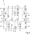
- Fig. 4 shows a schematic representation of a floor of the building in which the lighting system 10 is arranged. It can be seen that a plurality of rooms are provided in which beacons 16 are arranged, each of which emits specific identification data using respective radio signals 18. In addition, controllable devices 38 are arranged in the respective rooms and can be controlled using the method described above. Not shown in Fig. 4 the building management facility 42.
- the beacons 16 are arranged in respective lighting devices 12 (not shown), as already shown in FIG Figures 1 and 2 has been explained.
- a user is positioned with his communication terminal 34, the smartphone.
- the communication terminal 34 receives two radio signals 18 from two beacons 16 arranged in the room 78.
- an exact position of the communication terminal 34 can now be determined.
- Present the communication terminal 34 is located in room 78 as a predetermined area.
- controllable devices 38 which are not further specified and which can represent a blind, for example.
- the controllable device 38 can also be a heating or air conditioning device.
- controllable devices 38 of the room 78 can be controlled by means of the communication terminal 34.
- controllable devices 38 of the room 78 are assigned to the beacons 16 of the room 78.
- a spatial assignment is preferably provided.
- controllable devices 38 are arranged, which, however, are assigned to other beacons 16, namely the beacons 16, which are also arranged in the room 80.
- the controllable devices 38 of the room 80 cannot be controlled by the communication terminal 34, which is arranged in the room 78.
- the controllable devices 38 which cannot be controlled in the currently shown position of the communication terminal 34 in room 78, are marked with a lock symbol. In the present case, these are the controllable devices 38 outside the room 78.
- the communication terminal 34 determines its own position within the building from the specific identification data.
- one's own position is within the room 78.
- a layout plan of the lighting devices 12 is used, which contains the beacons 16, which include respective specific identification data. In this way, an exact position can be determined from a comparison of the received radio signals 18 and a field strength measurement of the radio signals 18.
- the communication terminal 34 preferably communicates with the central data processing 74, with both a wired and a wireless communication connection as well as combinations thereof being possible.
- the central data processing 74 authenticates a location of the communication terminal 34 and then forwards the control commands or the corresponding data to the corresponding controllable devices such as the blinds 38.
- wired and wireless communication connections and combinations thereof can also be used as communication channels.
- Fig. 3 shows a further embodiment for a lighting system 10, which does not fall within the wording of the claims, this embodiment being based on the previously described, according to Fig. 2 already explained, design for a lighting system 10 is based, which is why additional reference is made to the relevant statements.
- the communication terminal 34 establishes a communication connection 40 directly to the blind 38.
- the communication connection 40 is preferably designed to be wireless. However, depending on the type of communication terminal 34, it can also be wired or formed by a combination thereof.
- the communication terminal 34 can determine its own position within the specified area from the specific identification data of the beacon 16. To determine one's own position, a layout plan of the lighting device 12 or the beacons 16 arranged therein is used in the present case, in which the respective specific identification data of the Beacon 16 of the lighting devices 12, 20 are deposited. In this way, the position and thus position data can be determined from a comparison of the radio signal and a field strength measurement.
- the communication terminal 34 therefore communicates directly with the controllable device, in this case the blind 38.
- the location of the communication terminal 34 is authenticated by the communication terminal 34 itself.
Landscapes
- Engineering & Computer Science (AREA)
- Computer Networks & Wireless Communication (AREA)
- Physics & Mathematics (AREA)
- General Physics & Mathematics (AREA)
- Databases & Information Systems (AREA)
- Signal Processing (AREA)
- Circuit Arrangement For Electric Light Sources In General (AREA)
- Selective Calling Equipment (AREA)
- Mobile Radio Communication Systems (AREA)
Claims (17)
- Procédé de commande d'au moins un dispositif commandable (38) disposé dans une zone prédéterminée au moyen d'un terminal de communication (34), dans lequel un dispositif émetteur (16) transmet sans fil un signal radio (18) avec des données d'identification propres à l'émetteur dispositif d'éclairage (16) et dans lequel le dispositif de transmission (16) est agencé dans ou directement sur le dispositif d'éclairage (12), avec les étapes :- affecter le au moins un dispositif commandable (38) au dispositif émetteur (16),- recevoir le signal radio au moyen de la borne de communication (34),- évaluer du signal radio pour enregistrer les données d'identification spécifiques,- déterminer le au moins un dispositif commandable (38) affecté au dispositif émetteur (16) sur la base des données d'identification spécifiques enregistrées,- établir une connexion de communication entre le au moins un dispositif (38) et le terminal de communication (34) et- transmettre de données correspondant à une commande de contrôle du au moins un dispositif (38) et/ou du dispositif émetteur (16) lui-même, l'établissement du lien de communication comprenant que le lien de communication est établi au moins via un centre de contrôle ( 42), le au moins un dispositif contrôlable (38) établit automatiquement une liaison de communication avec le dispositif émetteur (16), le dispositif contrôlable (38) étant associé au dispositif émetteur (16) .
- Procédé selon la revendication 1, caractérisé en ce que la détermination comprend la fourniture de données de libération qui permettent au dispositif contrôlable (38) d'exécuter la commande de contrôle du terminal de communication (34) et/qui permettent au terminal de communication (34) d'émettre la commande de contrôle au dispositif contrôlable (38).
- Procédé selon la revendication 2, caractérisé en ce que la détermination des données de libération comprend la détermination des données de position pour une position du terminal de communication (34) au moins en utilisant les données d'identification spécifiques du dispositif de transmission (16) et en utilisant les données de position déterminées pour déterminer si le terminal de communication (34) est positionné dans la zone spécifiée.
- Procédé selon l'une quelconque des revendications précédentes, caractérisé en ce que
la détermination comprend l'installation d'un programme informatique spécifique pour une unité informatique du terminal de communication (34) . - Procédé selon l'une quelconque des revendications précédentes, caractérisé en ce que
la détermination comprend une comparaison avec une base de données contenant des données concernant au moins le dispositif d'éclairage (12), le au moins un dispositif contrôlable (38) et la zone prédéterminée. - Procédé selon l'une quelconque des revendications précédentes, caractérisé en ce que
l'établissement de la liaison de communication comprend l'établissement d'une liaison de communication vers le centre de contrôle (42), dans lequel le au moins un dispositif contrôlable (38) est commandé via le centre de commande (42). - Procédé selon l'une quelconque des revendications précédentes, caractérisé en ce que
dans le but d'authentifier la position du terminal de communication (34), les données de position sont comparées avec la zone spécifiée et les données de contrôle ne sont transmises qu'ensuite au au moins un dispositif contrôlable (38) et/ou au dispositif contrôlable ( 38) ne transmet alors la den Data to control que la commande de contrôle correspondante lorsque la position du terminal de communication (34) est authentifiée. - Procédé selon l'une quelconque des revendications 2 à 7,
caractérisé en ce que
les données de libération comprennent des informations d'autorisation, les informations d'autorisation étant spécifiques à un terminal de communication spécifié individuel (34) ou à un groupe spécifié de terminaux de communication (34). - Procédé selon l'une quelconque des revendications précédentes, caractérisé en ce que
le dispositif émetteur (16) est au moins partiellement alimenté en énergie électrique via le dispositif d'éclairage (12) pour son fonctionnement prévu, de préférence indépendamment du fonctionnement prévu du dispositif d'éclairage (12). - Procédé selon l'une quelconque des revendications précédentes, caractérisé en ce que
un profil de réglage attribué au terminal de communication (34) est utilisé pour commander le au moins un dispositif commandable (38). - Procédé selon la revendication 10, caractérisé en ce que
le au moins un dispositif commandable (38) est commandé automatiquement selon le profil de réglage dès que le terminal de communication (34) reçoit le signal radio (18). - Procédé selon la revendication 10 ou 11, caractérisé en ce que
la commande du au moins un dispositif commandable (38) comprend automatiquement l'adoption d'un réglage initial lorsque le terminal de communication (34) est hors d'une plage de réception par rapport au signal radio (18). - Procédé selon l'une quelconque des revendications précédentes, caractérisé en ce que
la commande comprend également la commande du dispositif de transmission (16). - Procédé selon l'une quelconque des revendications précédentes, caractérisé en ce que
le au moins un dispositif (38) est commandé au moins partiellement automatiquement sur la base d'au moins un paramètre approprié. - Procédé selon l'une quelconque des revendications précédentes, caractérisé en ce que,
lorsque le terminal de communication (34) reçoit le signal radio (18), des mises à jour de programmes informatiques sont proposées. - Procédé selon la revendication 15, caractérisé en ce que
la mise à jour est effectuée automatiquement dès que le terminal de communication (34) arrive à portée de communication du dispositif émetteur (16). - Système (10) pour contrôler au moins un dispositif contrôlable (38) situé dans une zone prédéterminée, comprenant :- le dispositif commandable (38),- un dispositif de transmission (16) qui transmet sans fil un signal radio (18) avec des données d'identification propres au dispositif de transmission (16), le au moins un dispositif commandable (38) étant affecté au dispositif de transmission (16), le dispositif de transmission (16) étant dans ou étant disposé directement sur le dispositif d'éclairage (12),- un terminal de communication (34) pour commander le dispositif commandable (38) et/ou le dispositif émetteur (16) lui-même, le terminal de communication (34) étant agencé pour recevoir le signal radio et l'évaluer afin d'enregistrer l'identification spécifique données,- une unité de détermination (40) pour déterminer le au moins un dispositif commandable (38) affecté au dispositif émetteur (16) sur la base des données d'identification spécifiques enregistrées,- dans lequel une connexion de communication peut être établie entre le au moins un dispositif (38) et le terminal de communication (34) afin de transmettre des données correspondant à une commande de contrôle pour contrôler le au moins un dispositif contrôlable (38), l'établissement du connexion de communication étant établie au moins via un centre de contrôle (42), dans lequel le au moins un dispositif contrôlable (38) est conçu pour établir automatiquement une connexion de communication avec le dispositif de transmission (16), le dispositif contrôlable (38) étant affecté à le dispositif de transmission (16)
Applications Claiming Priority (2)
| Application Number | Priority Date | Filing Date | Title |
|---|---|---|---|
| DE102016125661.7A DE102016125661A1 (de) | 2016-12-23 | 2016-12-23 | Steuern von wenigstens einer in einem durch eine Leuchteinrichtung vorgegebenen Bereich angeordneten steuerbaren Vorrichtung |
| PCT/EP2017/084367 WO2018115433A1 (fr) | 2016-12-23 | 2017-12-22 | Commande d'au moins un dispositif commandable disposé dans une zone prédéterminée par un dispositif d'éclairage |
Publications (2)
| Publication Number | Publication Date |
|---|---|
| EP3559923A1 EP3559923A1 (fr) | 2019-10-30 |
| EP3559923B1 true EP3559923B1 (fr) | 2023-09-13 |
Family
ID=60888432
Family Applications (1)
| Application Number | Title | Priority Date | Filing Date |
|---|---|---|---|
| EP17822688.2A Active EP3559923B1 (fr) | 2016-12-23 | 2017-12-22 | Commande d'au moins un dispositif commandable disposé dans une zone prédéterminée par un dispositif d'éclairage |
Country Status (5)
| Country | Link |
|---|---|
| US (1) | US20200100087A1 (fr) |
| EP (1) | EP3559923B1 (fr) |
| CN (1) | CN110100269A (fr) |
| DE (1) | DE102016125661A1 (fr) |
| WO (1) | WO2018115433A1 (fr) |
Families Citing this family (1)
| Publication number | Priority date | Publication date | Assignee | Title |
|---|---|---|---|---|
| DE102023110849A1 (de) * | 2023-04-27 | 2024-10-31 | Ebm-Papst Mulfingen Gmbh & Co. Kg | Strömungserzeugungseinrichtung und Verfahren zum Betreiben einer Strömungserzeugungseinrichtung |
Citations (2)
| Publication number | Priority date | Publication date | Assignee | Title |
|---|---|---|---|---|
| US20020197963A1 (en) * | 2001-06-01 | 2002-12-26 | Deutsches Zentrum Fur Luft-Und Raumfahrt E. V. | Data communications system including a local beacon |
| WO2016056540A1 (fr) * | 2014-10-07 | 2016-04-14 | ヤマハ株式会社 | Dispositif d'instruction, programme, système d'instruction et procédé d'instruction |
Family Cites Families (14)
| Publication number | Priority date | Publication date | Assignee | Title |
|---|---|---|---|---|
| US7243366B2 (en) * | 2001-11-15 | 2007-07-10 | General Instrument Corporation | Key management protocol and authentication system for secure internet protocol rights management architecture |
| CN1925527A (zh) * | 2005-08-29 | 2007-03-07 | 吕安姿 | 一种利用移动电话控制家用电器的方法及其系统 |
| US9345115B2 (en) * | 2009-09-05 | 2016-05-17 | Enlighted, Inc. | Distributed light fixture beacon transmission |
| FR2952499A1 (fr) * | 2009-11-12 | 2011-05-13 | France Telecom | Procede d'allocation de ressources de transmission de donnees, procede de basculement, point d'acces, terminal, programme d'ordinateur et signal correspondants |
| CN101950020A (zh) * | 2010-06-23 | 2011-01-19 | 焦利民 | 一种移动设备智能定位系统 |
| US9204291B2 (en) * | 2012-10-12 | 2015-12-01 | Crestron Electronics, Inc. | User identification and location determination in control applications |
| KR101241793B1 (ko) * | 2012-11-01 | 2013-03-15 | (주)위니텍 | 실내 측위용 비콘 모듈을 구비한 형광등 소켓 커넥터 및 이를 이용한 실내 측위 시스템 |
| KR20140105968A (ko) * | 2013-02-25 | 2014-09-03 | 삼성전자주식회사 | 조명 제어 시스템 및 그 제어방법 |
| CN203261557U (zh) * | 2013-05-29 | 2013-10-30 | 何焱 | 室内智能感应节能开关电路 |
| CN103499960B (zh) * | 2013-10-09 | 2016-05-11 | 广东索博智能科技有限公司 | 智能家居无线控制系统 |
| CN106062842B (zh) * | 2014-01-30 | 2019-11-05 | 飞利浦灯具控股公司 | 照明系统以及用于控制其的控制器和移动用户终端 |
| EP3135079B1 (fr) * | 2014-04-25 | 2019-08-07 | Signify Holding B.V. | Accès à un éclairage basé sur une zone |
| CN103991465B (zh) * | 2014-05-30 | 2016-07-06 | 南车南京浦镇车辆有限公司 | 有轨电车安全式无线道岔控制系统及控制方法 |
| CA3268763A1 (en) * | 2015-08-05 | 2025-10-30 | Lutron Technology Company Llc | Load control system responsive to the location of an occupant and/or mobile device |
-
2016
- 2016-12-23 DE DE102016125661.7A patent/DE102016125661A1/de active Pending
-
2017
- 2017-12-22 EP EP17822688.2A patent/EP3559923B1/fr active Active
- 2017-12-22 CN CN201780080011.7A patent/CN110100269A/zh active Pending
- 2017-12-22 US US16/472,046 patent/US20200100087A1/en not_active Abandoned
- 2017-12-22 WO PCT/EP2017/084367 patent/WO2018115433A1/fr not_active Ceased
Patent Citations (3)
| Publication number | Priority date | Publication date | Assignee | Title |
|---|---|---|---|---|
| US20020197963A1 (en) * | 2001-06-01 | 2002-12-26 | Deutsches Zentrum Fur Luft-Und Raumfahrt E. V. | Data communications system including a local beacon |
| WO2016056540A1 (fr) * | 2014-10-07 | 2016-04-14 | ヤマハ株式会社 | Dispositif d'instruction, programme, système d'instruction et procédé d'instruction |
| EP3206410A1 (fr) * | 2014-10-07 | 2017-08-16 | Yamaha Corporation | Dispositif d'instruction, programme, système d'instruction et procédé d'instruction |
Also Published As
| Publication number | Publication date |
|---|---|
| EP3559923A1 (fr) | 2019-10-30 |
| DE102016125661A1 (de) | 2018-06-28 |
| US20200100087A1 (en) | 2020-03-26 |
| CN110100269A (zh) | 2019-08-06 |
| WO2018115433A1 (fr) | 2018-06-28 |
Similar Documents
| Publication | Publication Date | Title |
|---|---|---|
| EP3560297B1 (fr) | Installation ou modification d'un programme informatique exécutable dans un système d'éclairage | |
| WO2018086779A1 (fr) | Activation d'un système d'émission d'un dispositif d'éclairage | |
| EP2983145A1 (fr) | Socle d'alerte et base de raccordement destinés à l'installation amovible d'un dispositif d'alerte aux dangers doté d'un dispositif radio destiné à émettre des données de position de l'emplacement de montage du socle d'alerte ou de la base de raccordement et/ou d'une référence relative auxdites données de position | |
| EP3469859B1 (fr) | Attribution d'adresses et configuration de composants d'un système d'éclairage au moyen d'un transpondeur | |
| EP3339873B1 (fr) | Fonctionnement d'un dispositif d'émission d'une installation d'éclairage comportant un dispositif d'éclairage | |
| DE102017102597A1 (de) | Managementsystem für elektrische Vorrichtungen | |
| EP3427548B1 (fr) | Système d'éclairage à configuration automatique de balises | |
| EP3559923A1 (fr) | Commande d'au moins un dispositif commandable disposé dans une zone prédéterminée par un dispositif d'éclairage | |
| DE102021202916B4 (de) | Anordnung und Verfahren für eine Inbetriebsetzung einer Brandmeldeanlage | |
| WO2018091165A1 (fr) | Création d'un plan d'installation d'un système d'éclairage | |
| DE102016125684A1 (de) | Leuchteinrichtung mit einer Sendeeinrichtung und einem Leuchtmittel und Verfahren zu deren Betrieb | |
| EP3446553B1 (fr) | Appareil d'éclairage avec transmission de données de fonctionnement | |
| EP3619933A1 (fr) | Chiffrement de balises | |
| WO2017153147A1 (fr) | Dispositif d'éclairage à limitation de courant pour moyen de communication | |
| WO2018086780A1 (fr) | Système d'éclairage avec évaluation de signal d'analyse | |
| DE102023130779A1 (de) | Standortbezogene zuordnung technischer komponenten mittels optischer marker | |
| WO2019192852A1 (fr) | Étalonnage d'un dispositif d'émission | |
| DE102018107921A1 (de) | Betreiben einer Sendeeinrichtung in Verbindung mit einem Kommunikationsgerät | |
| DE102015119629A1 (de) | Ortung eines Objekts mit Sender |
Legal Events
| Date | Code | Title | Description |
|---|---|---|---|
| STAA | Information on the status of an ep patent application or granted ep patent |
Free format text: STATUS: UNKNOWN |
|
| STAA | Information on the status of an ep patent application or granted ep patent |
Free format text: STATUS: THE INTERNATIONAL PUBLICATION HAS BEEN MADE |
|
| PUAI | Public reference made under article 153(3) epc to a published international application that has entered the european phase |
Free format text: ORIGINAL CODE: 0009012 |
|
| STAA | Information on the status of an ep patent application or granted ep patent |
Free format text: STATUS: REQUEST FOR EXAMINATION WAS MADE |
|
| 17P | Request for examination filed |
Effective date: 20190604 |
|
| AK | Designated contracting states |
Kind code of ref document: A1 Designated state(s): AL AT BE BG CH CY CZ DE DK EE ES FI FR GB GR HR HU IE IS IT LI LT LU LV MC MK MT NL NO PL PT RO RS SE SI SK SM TR |
|
| AX | Request for extension of the european patent |
Extension state: BA ME |
|
| DAV | Request for validation of the european patent (deleted) | ||
| DAX | Request for extension of the european patent (deleted) | ||
| STAA | Information on the status of an ep patent application or granted ep patent |
Free format text: STATUS: EXAMINATION IS IN PROGRESS |
|
| 17Q | First examination report despatched |
Effective date: 20200730 |
|
| RAP1 | Party data changed (applicant data changed or rights of an application transferred) |
Owner name: OSRAM GMBH |
|
| GRAP | Despatch of communication of intention to grant a patent |
Free format text: ORIGINAL CODE: EPIDOSNIGR1 |
|
| STAA | Information on the status of an ep patent application or granted ep patent |
Free format text: STATUS: GRANT OF PATENT IS INTENDED |
|
| RIC1 | Information provided on ipc code assigned before grant |
Ipc: H05B 47/19 20200101ALI20230331BHEP Ipc: G08C 17/02 20060101AFI20230331BHEP |
|
| INTG | Intention to grant announced |
Effective date: 20230419 |
|
| P01 | Opt-out of the competence of the unified patent court (upc) registered |
Effective date: 20230613 |
|
| GRAS | Grant fee paid |
Free format text: ORIGINAL CODE: EPIDOSNIGR3 |
|
| GRAA | (expected) grant |
Free format text: ORIGINAL CODE: 0009210 |
|
| STAA | Information on the status of an ep patent application or granted ep patent |
Free format text: STATUS: THE PATENT HAS BEEN GRANTED |
|
| AK | Designated contracting states |
Kind code of ref document: B1 Designated state(s): AL AT BE BG CH CY CZ DE DK EE ES FI FR GB GR HR HU IE IS IT LI LT LU LV MC MK MT NL NO PL PT RO RS SE SI SK SM TR |
|
| REG | Reference to a national code |
Ref country code: GB Ref legal event code: FG4D Free format text: NOT ENGLISH |
|
| REG | Reference to a national code |
Ref country code: CH Ref legal event code: EP |
|
| REG | Reference to a national code |
Ref country code: DE Ref legal event code: R096 Ref document number: 502017015383 Country of ref document: DE |
|
| REG | Reference to a national code |
Ref country code: IE Ref legal event code: FG4D Free format text: LANGUAGE OF EP DOCUMENT: GERMAN |
|
| REG | Reference to a national code |
Ref country code: LT Ref legal event code: MG9D |
|
| REG | Reference to a national code |
Ref country code: NL Ref legal event code: MP Effective date: 20230913 |
|
| PG25 | Lapsed in a contracting state [announced via postgrant information from national office to epo] |
Ref country code: GR Free format text: LAPSE BECAUSE OF FAILURE TO SUBMIT A TRANSLATION OF THE DESCRIPTION OR TO PAY THE FEE WITHIN THE PRESCRIBED TIME-LIMIT Effective date: 20231214 |
|
| PG25 | Lapsed in a contracting state [announced via postgrant information from national office to epo] |
Ref country code: SE Free format text: LAPSE BECAUSE OF FAILURE TO SUBMIT A TRANSLATION OF THE DESCRIPTION OR TO PAY THE FEE WITHIN THE PRESCRIBED TIME-LIMIT Effective date: 20230913 Ref country code: RS Free format text: LAPSE BECAUSE OF FAILURE TO SUBMIT A TRANSLATION OF THE DESCRIPTION OR TO PAY THE FEE WITHIN THE PRESCRIBED TIME-LIMIT Effective date: 20230913 Ref country code: NO Free format text: LAPSE BECAUSE OF FAILURE TO SUBMIT A TRANSLATION OF THE DESCRIPTION OR TO PAY THE FEE WITHIN THE PRESCRIBED TIME-LIMIT Effective date: 20231213 Ref country code: LV Free format text: LAPSE BECAUSE OF FAILURE TO SUBMIT A TRANSLATION OF THE DESCRIPTION OR TO PAY THE FEE WITHIN THE PRESCRIBED TIME-LIMIT Effective date: 20230913 Ref country code: LT Free format text: LAPSE BECAUSE OF FAILURE TO SUBMIT A TRANSLATION OF THE DESCRIPTION OR TO PAY THE FEE WITHIN THE PRESCRIBED TIME-LIMIT Effective date: 20230913 Ref country code: HR Free format text: LAPSE BECAUSE OF FAILURE TO SUBMIT A TRANSLATION OF THE DESCRIPTION OR TO PAY THE FEE WITHIN THE PRESCRIBED TIME-LIMIT Effective date: 20230913 Ref country code: GR Free format text: LAPSE BECAUSE OF FAILURE TO SUBMIT A TRANSLATION OF THE DESCRIPTION OR TO PAY THE FEE WITHIN THE PRESCRIBED TIME-LIMIT Effective date: 20231214 Ref country code: FI Free format text: LAPSE BECAUSE OF FAILURE TO SUBMIT A TRANSLATION OF THE DESCRIPTION OR TO PAY THE FEE WITHIN THE PRESCRIBED TIME-LIMIT Effective date: 20230913 |
|
| PG25 | Lapsed in a contracting state [announced via postgrant information from national office to epo] |
Ref country code: NL Free format text: LAPSE BECAUSE OF FAILURE TO SUBMIT A TRANSLATION OF THE DESCRIPTION OR TO PAY THE FEE WITHIN THE PRESCRIBED TIME-LIMIT Effective date: 20230913 |
|
| PG25 | Lapsed in a contracting state [announced via postgrant information from national office to epo] |
Ref country code: IS Free format text: LAPSE BECAUSE OF FAILURE TO SUBMIT A TRANSLATION OF THE DESCRIPTION OR TO PAY THE FEE WITHIN THE PRESCRIBED TIME-LIMIT Effective date: 20240113 |
|
| PG25 | Lapsed in a contracting state [announced via postgrant information from national office to epo] |
Ref country code: ES Free format text: LAPSE BECAUSE OF FAILURE TO SUBMIT A TRANSLATION OF THE DESCRIPTION OR TO PAY THE FEE WITHIN THE PRESCRIBED TIME-LIMIT Effective date: 20230913 |
|
| PG25 | Lapsed in a contracting state [announced via postgrant information from national office to epo] |
Ref country code: SM Free format text: LAPSE BECAUSE OF FAILURE TO SUBMIT A TRANSLATION OF THE DESCRIPTION OR TO PAY THE FEE WITHIN THE PRESCRIBED TIME-LIMIT Effective date: 20230913 Ref country code: RO Free format text: LAPSE BECAUSE OF FAILURE TO SUBMIT A TRANSLATION OF THE DESCRIPTION OR TO PAY THE FEE WITHIN THE PRESCRIBED TIME-LIMIT Effective date: 20230913 Ref country code: IS Free format text: LAPSE BECAUSE OF FAILURE TO SUBMIT A TRANSLATION OF THE DESCRIPTION OR TO PAY THE FEE WITHIN THE PRESCRIBED TIME-LIMIT Effective date: 20240113 Ref country code: ES Free format text: LAPSE BECAUSE OF FAILURE TO SUBMIT A TRANSLATION OF THE DESCRIPTION OR TO PAY THE FEE WITHIN THE PRESCRIBED TIME-LIMIT Effective date: 20230913 Ref country code: EE Free format text: LAPSE BECAUSE OF FAILURE TO SUBMIT A TRANSLATION OF THE DESCRIPTION OR TO PAY THE FEE WITHIN THE PRESCRIBED TIME-LIMIT Effective date: 20230913 Ref country code: CZ Free format text: LAPSE BECAUSE OF FAILURE TO SUBMIT A TRANSLATION OF THE DESCRIPTION OR TO PAY THE FEE WITHIN THE PRESCRIBED TIME-LIMIT Effective date: 20230913 Ref country code: PT Free format text: LAPSE BECAUSE OF FAILURE TO SUBMIT A TRANSLATION OF THE DESCRIPTION OR TO PAY THE FEE WITHIN THE PRESCRIBED TIME-LIMIT Effective date: 20240115 Ref country code: SK Free format text: LAPSE BECAUSE OF FAILURE TO SUBMIT A TRANSLATION OF THE DESCRIPTION OR TO PAY THE FEE WITHIN THE PRESCRIBED TIME-LIMIT Effective date: 20230913 |
|
| PG25 | Lapsed in a contracting state [announced via postgrant information from national office to epo] |
Ref country code: PL Free format text: LAPSE BECAUSE OF FAILURE TO SUBMIT A TRANSLATION OF THE DESCRIPTION OR TO PAY THE FEE WITHIN THE PRESCRIBED TIME-LIMIT Effective date: 20230913 Ref country code: IT Free format text: LAPSE BECAUSE OF FAILURE TO SUBMIT A TRANSLATION OF THE DESCRIPTION OR TO PAY THE FEE WITHIN THE PRESCRIBED TIME-LIMIT Effective date: 20230913 |
|
| REG | Reference to a national code |
Ref country code: DE Ref legal event code: R097 Ref document number: 502017015383 Country of ref document: DE |
|
| PG25 | Lapsed in a contracting state [announced via postgrant information from national office to epo] |
Ref country code: DK Free format text: LAPSE BECAUSE OF FAILURE TO SUBMIT A TRANSLATION OF THE DESCRIPTION OR TO PAY THE FEE WITHIN THE PRESCRIBED TIME-LIMIT Effective date: 20230913 |
|
| PLBE | No opposition filed within time limit |
Free format text: ORIGINAL CODE: 0009261 |
|
| STAA | Information on the status of an ep patent application or granted ep patent |
Free format text: STATUS: NO OPPOSITION FILED WITHIN TIME LIMIT |
|
| PG25 | Lapsed in a contracting state [announced via postgrant information from national office to epo] |
Ref country code: DK Free format text: LAPSE BECAUSE OF FAILURE TO SUBMIT A TRANSLATION OF THE DESCRIPTION OR TO PAY THE FEE WITHIN THE PRESCRIBED TIME-LIMIT Effective date: 20230913 |
|
| REG | Reference to a national code |
Ref country code: CH Ref legal event code: PL |
|
| 26N | No opposition filed |
Effective date: 20240614 |
|
| PG25 | Lapsed in a contracting state [announced via postgrant information from national office to epo] |
Ref country code: LU Free format text: LAPSE BECAUSE OF NON-PAYMENT OF DUE FEES Effective date: 20231222 |
|
| PG25 | Lapsed in a contracting state [announced via postgrant information from national office to epo] |
Ref country code: MC Free format text: LAPSE BECAUSE OF FAILURE TO SUBMIT A TRANSLATION OF THE DESCRIPTION OR TO PAY THE FEE WITHIN THE PRESCRIBED TIME-LIMIT Effective date: 20230913 |
|
| GBPC | Gb: european patent ceased through non-payment of renewal fee |
Effective date: 20231222 |
|
| REG | Reference to a national code |
Ref country code: BE Ref legal event code: MM Effective date: 20231231 |
|
| PG25 | Lapsed in a contracting state [announced via postgrant information from national office to epo] |
Ref country code: MC Free format text: LAPSE BECAUSE OF FAILURE TO SUBMIT A TRANSLATION OF THE DESCRIPTION OR TO PAY THE FEE WITHIN THE PRESCRIBED TIME-LIMIT Effective date: 20230913 Ref country code: LU Free format text: LAPSE BECAUSE OF NON-PAYMENT OF DUE FEES Effective date: 20231222 |
|
| REG | Reference to a national code |
Ref country code: IE Ref legal event code: MM4A |
|
| PG25 | Lapsed in a contracting state [announced via postgrant information from national office to epo] |
Ref country code: IE Free format text: LAPSE BECAUSE OF NON-PAYMENT OF DUE FEES Effective date: 20231222 |
|
| PG25 | Lapsed in a contracting state [announced via postgrant information from national office to epo] |
Ref country code: GB Free format text: LAPSE BECAUSE OF NON-PAYMENT OF DUE FEES Effective date: 20231222 |
|
| PG25 | Lapsed in a contracting state [announced via postgrant information from national office to epo] |
Ref country code: BE Free format text: LAPSE BECAUSE OF NON-PAYMENT OF DUE FEES Effective date: 20231231 |
|
| PG25 | Lapsed in a contracting state [announced via postgrant information from national office to epo] |
Ref country code: FR Free format text: LAPSE BECAUSE OF NON-PAYMENT OF DUE FEES Effective date: 20231231 |
|
| PG25 | Lapsed in a contracting state [announced via postgrant information from national office to epo] |
Ref country code: CH Free format text: LAPSE BECAUSE OF NON-PAYMENT OF DUE FEES Effective date: 20231231 |
|
| PG25 | Lapsed in a contracting state [announced via postgrant information from national office to epo] |
Ref country code: SI Free format text: LAPSE BECAUSE OF FAILURE TO SUBMIT A TRANSLATION OF THE DESCRIPTION OR TO PAY THE FEE WITHIN THE PRESCRIBED TIME-LIMIT Effective date: 20230913 |
|
| PG25 | Lapsed in a contracting state [announced via postgrant information from national office to epo] |
Ref country code: SI Free format text: LAPSE BECAUSE OF FAILURE TO SUBMIT A TRANSLATION OF THE DESCRIPTION OR TO PAY THE FEE WITHIN THE PRESCRIBED TIME-LIMIT Effective date: 20230913 Ref country code: IE Free format text: LAPSE BECAUSE OF NON-PAYMENT OF DUE FEES Effective date: 20231222 Ref country code: GB Free format text: LAPSE BECAUSE OF NON-PAYMENT OF DUE FEES Effective date: 20231222 Ref country code: FR Free format text: LAPSE BECAUSE OF NON-PAYMENT OF DUE FEES Effective date: 20231231 Ref country code: CH Free format text: LAPSE BECAUSE OF NON-PAYMENT OF DUE FEES Effective date: 20231231 Ref country code: BE Free format text: LAPSE BECAUSE OF NON-PAYMENT OF DUE FEES Effective date: 20231231 |
|
| PG25 | Lapsed in a contracting state [announced via postgrant information from national office to epo] |
Ref country code: BG Free format text: LAPSE BECAUSE OF FAILURE TO SUBMIT A TRANSLATION OF THE DESCRIPTION OR TO PAY THE FEE WITHIN THE PRESCRIBED TIME-LIMIT Effective date: 20230913 |
|
| PG25 | Lapsed in a contracting state [announced via postgrant information from national office to epo] |
Ref country code: BG Free format text: LAPSE BECAUSE OF FAILURE TO SUBMIT A TRANSLATION OF THE DESCRIPTION OR TO PAY THE FEE WITHIN THE PRESCRIBED TIME-LIMIT Effective date: 20230913 |
|
| REG | Reference to a national code |
Ref country code: DE Ref legal event code: R082 Ref document number: 502017015383 Country of ref document: DE Representative=s name: IMPULS LEGAL PARTG MBB, DE |
|
| PGFP | Annual fee paid to national office [announced via postgrant information from national office to epo] |
Ref country code: DE Payment date: 20241210 Year of fee payment: 8 |
|
| REG | Reference to a national code |
Ref country code: AT Ref legal event code: MM01 Ref document number: 1612101 Country of ref document: AT Kind code of ref document: T Effective date: 20231222 |
|
| PG25 | Lapsed in a contracting state [announced via postgrant information from national office to epo] |
Ref country code: AT Free format text: LAPSE BECAUSE OF NON-PAYMENT OF DUE FEES Effective date: 20231222 |
|
| PG25 | Lapsed in a contracting state [announced via postgrant information from national office to epo] |
Ref country code: CY Free format text: LAPSE BECAUSE OF FAILURE TO SUBMIT A TRANSLATION OF THE DESCRIPTION OR TO PAY THE FEE WITHIN THE PRESCRIBED TIME-LIMIT; INVALID AB INITIO Effective date: 20171222 |
|
| PG25 | Lapsed in a contracting state [announced via postgrant information from national office to epo] |
Ref country code: HU Free format text: LAPSE BECAUSE OF FAILURE TO SUBMIT A TRANSLATION OF THE DESCRIPTION OR TO PAY THE FEE WITHIN THE PRESCRIBED TIME-LIMIT; INVALID AB INITIO Effective date: 20171222 |
|
| PG25 | Lapsed in a contracting state [announced via postgrant information from national office to epo] |
Ref country code: TR Free format text: LAPSE BECAUSE OF FAILURE TO SUBMIT A TRANSLATION OF THE DESCRIPTION OR TO PAY THE FEE WITHIN THE PRESCRIBED TIME-LIMIT Effective date: 20230913 |