EP3559581B1 - Plattenwärmetauscher - Google Patents
Plattenwärmetauscher Download PDFInfo
- Publication number
- EP3559581B1 EP3559581B1 EP17807877.0A EP17807877A EP3559581B1 EP 3559581 B1 EP3559581 B1 EP 3559581B1 EP 17807877 A EP17807877 A EP 17807877A EP 3559581 B1 EP3559581 B1 EP 3559581B1
- Authority
- EP
- European Patent Office
- Prior art keywords
- heat exchanger
- plate
- exchanger plates
- portholes
- inlet
- Prior art date
- Legal status (The legal status is an assumption and is not a legal conclusion. Google has not performed a legal analysis and makes no representation as to the accuracy of the status listed.)
- Active
Links
- 239000003507 refrigerant Substances 0.000 description 2
- 239000002826 coolant Substances 0.000 description 1
- 238000010438 heat treatment Methods 0.000 description 1
- XLYOFNOQVPJJNP-UHFFFAOYSA-N water Substances O XLYOFNOQVPJJNP-UHFFFAOYSA-N 0.000 description 1
- 230000003313 weakening effect Effects 0.000 description 1
Images


Classifications
-
- F—MECHANICAL ENGINEERING; LIGHTING; HEATING; WEAPONS; BLASTING
- F28—HEAT EXCHANGE IN GENERAL
- F28D—HEAT-EXCHANGE APPARATUS, NOT PROVIDED FOR IN ANOTHER SUBCLASS, IN WHICH THE HEAT-EXCHANGE MEDIA DO NOT COME INTO DIRECT CONTACT
- F28D9/00—Heat-exchange apparatus having stationary plate-like or laminated conduit assemblies for both heat-exchange media, the media being in contact with different sides of a conduit wall
- F28D9/0093—Multi-circuit heat-exchangers, e.g. integrating different heat exchange sections in the same unit or heat-exchangers for more than two fluids
-
- F—MECHANICAL ENGINEERING; LIGHTING; HEATING; WEAPONS; BLASTING
- F28—HEAT EXCHANGE IN GENERAL
- F28D—HEAT-EXCHANGE APPARATUS, NOT PROVIDED FOR IN ANOTHER SUBCLASS, IN WHICH THE HEAT-EXCHANGE MEDIA DO NOT COME INTO DIRECT CONTACT
- F28D9/00—Heat-exchange apparatus having stationary plate-like or laminated conduit assemblies for both heat-exchange media, the media being in contact with different sides of a conduit wall
- F28D9/0031—Heat-exchange apparatus having stationary plate-like or laminated conduit assemblies for both heat-exchange media, the media being in contact with different sides of a conduit wall the conduits for one heat-exchange medium being formed by paired plates touching each other
- F28D9/0043—Heat-exchange apparatus having stationary plate-like or laminated conduit assemblies for both heat-exchange media, the media being in contact with different sides of a conduit wall the conduits for one heat-exchange medium being formed by paired plates touching each other the plates having openings therein for circulation of at least one heat-exchange medium from one conduit to another
- F28D9/005—Heat-exchange apparatus having stationary plate-like or laminated conduit assemblies for both heat-exchange media, the media being in contact with different sides of a conduit wall the conduits for one heat-exchange medium being formed by paired plates touching each other the plates having openings therein for circulation of at least one heat-exchange medium from one conduit to another the plates having openings therein for both heat-exchange media
-
- F—MECHANICAL ENGINEERING; LIGHTING; HEATING; WEAPONS; BLASTING
- F28—HEAT EXCHANGE IN GENERAL
- F28F—DETAILS OF HEAT-EXCHANGE AND HEAT-TRANSFER APPARATUS, OF GENERAL APPLICATION
- F28F2225/00—Reinforcing means
Definitions
- the present invention refers to a plate heat exchanger according to the preamble of claim 1.
- a plate heat exchanger is disclosed in US 6,164,371 .
- Such prior art plate heat exchangers for three media may have six ports, wherein four of the ports will be open to one plate interspace, closed to the following two plate interspaces, open to the following one plate interspace, closed to the following two plate interspace and so forth.
- the plate heat exchanger disclosed in US-6,164,371 is disadvantageous due to weakness around these four ports and therefore susceptible to collapsing. Every third plate interspace is closed at these four ports by means of portholes with a smaller diameter than the adjacent portholes. The outer flat area of the portholes with smaller diameter extends a longer distance into the port. In addition to reducing the free flow area of the ports, this solution results in a weakening of the heat exchanger plates in the area of these four portholes.
- the object of the present invention is to overcome the problems discussed above and to provide an improved plate heat exchanger having plate interspaces for three different media.
- the plate heat exchanger initially defined which is characterized in that the inner flat areas of the portholes of the second inlet and outlet ports of the heat exchanger plates, that enclose the second plate interspaces, are located at a distance from each other, and that the inner flat areas of the portholes of the second inlet and outlet ports of the heat exchanger plates, that enclose the third plate interspaces, adjoin each other and are located at one of the top plane and the bottom plane.
- the outer flat area of the portholes of all ports of all heat exchanger plates is located at one of the top plane and the bottom plane, the outer flat area of all heat exchanger plates will adjoin another outer flat area of an adjacent heat exchanger plate in the plate package. This structure ensures a high strength at the ports of the plate heat exchanger.
- the inner flat areas of the portholes of the second inlet and outlet ports of the heat exchanger plates, that enclose the second plate interspaces are located at a distance from each other and from the top and bottom planes (6,7), for instance between the bottom plane and the top plane, the second inlet and outlet ports may communicate with the second plate interspaces.
- the inner flat areas of the portholes of the second inlet and outlet ports of the heat exchanger plates that enclose the third plate interspaces adjoin each other and are located at one of the top plane and the bottom plane, the inner flat areas of the portholes of the second inlet and outlet ports of the heat exchanger plates that enclose the third plate interspaces will adjoin each other for all heat exchanger plates enclosing the third plate interspaces.
- the inner flat areas of the portholes of the third inlet and outlet ports of the heat exchanger plates, that enclose the third plate interspaces are located at a distance from each other and from the top and bottom planes (6,7), for instance between the bottom plane and the top plane, wherein the inner flat areas of the portholes of the third inlet and outlet ports of the heat exchanger plates, that enclose the second plate interspaces, adjoin each other and are located at one of the top plane and the bottom plane. Consequently, the third inlet and outlet ports of the plates enclosing the third plate interspaces may be configured in the same way as the second inlet and outlet portion of the heat exchanger plates enclosing the third plate interspaces.
- the outer flat area of the portholes of the first inlet and outlet ports of the heat exchanger plates adjoins the corrugation of the heat exchanger area.
- each of the portholes of the second inlet port has a diameter that is equal for all heat exchanger plates of the plate package.
- each of the portholes of the second outlet port has a diameter that is equal for all heat exchanger plates of the plate package.
- each of the portholes of the third inlet port has a diameter that is equal for all heat exchanger plates of the plate package.
- each of the portholes of the third outlet port has a diameter that is equal for all heat exchanger plates of the plate package.
- the diameter of the portholes of the second inlet port is equal to the diameter of the portholes of the third inlet port.
- the diameter of the portholes of the second outlet port is equal to the diameter of the portholes of third outlet ports.
- the heat exchanger plates comprises first heat exchanger plates and second heat exchanger plates provided in an alternating order in the plate package.
- each of the second plate interspaces is provided between one of the second heat exchanger plates and one of the first heat exchanger plates
- each of the third plate interspaces is provided between one of the second heat exchanger plates and one of the first heat exchanger plates.
- the inner flat areas of the portholes of the second inlet and outlet ports of the first heat exchanger plates, that adjoin the third plate interspaces, is located at the bottom plane.
- the inner flat areas of the portholes of the second inlet and outlet ports of the second heat exchanger plates, that adjoin the third plate interspaces, is located at the top plane.
- the inner flat areas of the portholes of the third inlet and outlet ports of the first heat exchanger plates, that adjoin the second plate interspaces, is located at the top plane.
- the inner flat areas of the portholes of the third inlet and outlet ports of the second heat exchanger plates, that adjoin the second plate interspaces, is located at the bottom plane.
- each of the first plate interspaces is provided between one of the first heat exchanger plates and one of the second heat exchanger plates.
- the first heat exchanger plates comprise a first end plate that adjoins an outermost one of the first plate interspaces
- the second heat exchanger plates comprise a second end plate that adjoins another outermost one of the first plate interspaces.
- the inner flat area of the portholes of the second inlet and outlet ports and the third inlet and outlet ports of the first end plate is located at the top plane.
- the inner flat areas of the first end plate may thus adjoin a frame plate of the plate heat exchanger.
- the inner flat area of the portholes of the second inlet and outlet ports and of the third inlet and outlet ports of the second end plate is located at the bottom plane.
- the inner flat areas of the second end plate may thus adjoin a pressure plate of the plate heat exchanger.
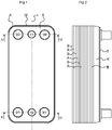
- Figs 1 to 4 disclose a plate heat exchanger comprising a plate package of heat exchanger plates A, A', A", B, B', B".
- the heat exchanger plates A, A', A", B, B', B" are stacked onto each other to form first plate interspaces 1 for a primary medium, second plate interspaces 2 for a first secondary medium and third plate interspaces 3 for a second secondary medium.
- the primary medium may be a heating or cooling medium, for instance hot or cold water.
- the first secondary medium may be a first refrigerant to be evaporated or condensed.
- the second secondary medium may be a second refrigerant to be evaporated or condensed.
- the plate interspaces 1-3 are arranged in the following order: a first plate interspace 1, a second plate interspace 2, a first plate interspace 1, a third plate interspace 3, a first plate interspace 1, a second plate interspace 2, a first plate interspace 1, a third plate interspace 3, a first plate interspace 1, a second plate interspace 2, a first plate interspace 1, a third plate interspace 3, a first plate interspace 1, a second plate interspace 2, a first plate interspace 1, a third plate interspace 3 and a first plate interspace 1.
- the plate heat exchanger comprises 13 plate interspaces 1-3. This is only an example, and it should be noted that the plate heat exchanger may comprise a smaller or larger number of plate interspaces 1-3.
- Each heat exchanger plate A, A', A", B, B', B" extends in parallel with an extension plane p and comprises a heat exchanger area 4 with a corrugation 5, see Figs 5 and 6 .
- the corrugation 5 extends between a top plane 6 and a bottom plane 7, see Figs 3 and 4 .
- the top plane 6 and the bottom plane 7 are parallel to each other and to the extension plane p.
- the extension plane p forms a central plane extending in the middle between the top plane 6 and the bottom plane 7.
- the corrugation 5 is formed by ridges and valleys.
- the corrugation 5 of ridges and valleys extends to a longitudinal center axis x and forms an angle of inclination with the longitudinal center axis x.
- the corrugation 5 form s an arrow pattern, as can be seen in Figs 5 and 6 .
- Other kinds of corrugations 5 are possible.
- the plate heat exchanger and the plate package also comprises a frame plate 8 on one side of the heat exchanger plates A, A', A", B, B', B" and a pressure plate 9 on the other side of the heat exchanger plates A, A', A", B, B', B".
- the frame plate 8 and the pressure plate 9 extend in parallel with the extension planes p of the heat exchanger plates A, A', A", B, B', B".
- the plate heat exchanger and the plate package comprises six ports 11, 12, 21, 22, 31, 32 as can be seen in Fig 1 .
- the ports 11, 12, 21, 22, 31, 32 extend through the heat exchanger plates A, A', A", B, B', B" and through the frame plate 8.
- the ports 11, 12, 21, 22, 31 and 32 comprise first inlet and outlet ports 11, 12, second inlet and outlet ports 21, 22 and third inlet and outlet ports 31, 32.
- the first inlet port 11 and the first outlet port 12 communicate with the first plate interspaces 1, and permit the supply and discharge of the primary medium to and from the first plate interspaces 1.
- the first inlet and outlet ports 11, 12 are closed to the second and third plate interspaces 2, 3.
- the second inlet port 21 and the second outlet port 22 communicate with the second plate interspaces 2, and permit the supply and discharge of the first secondary medium to and from the second plate interspaces 2.
- the second inlet and outlet ports 21, 22 are closed to the first and third plate interspaces 1, 3.
- the third inlet port 31 and the third outlet port 32 communicate with the third plate interspaces 3, and permit the supply and discharge of the second secondary medium to and from the third plate interspaces 3.
- the third inlet and outlet ports 31, 32 are closed to the first and second plate interspaces 1, 2.
- the second inlet and outlet 21, 22 are located to the left in Fig 1 , and the third inlet and outlet 31, 32 to the right in Fig 1 .
- the flow of the first secondary and second secondary media may alternatively extend diagonally, so that the second inlet 21 and the third outlet 32 are located to the left and the second outlet 22 and third inlet 31 to the right in Fig 1 .
- Each of the ports 11, 12, 21, 22, 31 and 32 is formed by a porthole 14 through each of the heat exchanger plates A, A', A", B, B', B", see Figs 5 and 6 .
- Each porthole 14 is surrounded by an outer flat area 15.
- the outer flat area 15 forms or define s a porthole edge 16 of the porthole 14.
- the outer flat area 15 is annular and extends in parallel with the extension plane p.
- the outer flat area 15 of portholes 14 the second inlet and outlet ports 21, 22 and of the third inlet and outlet ports 31, 32 is surrounded by an inner flat area 17, see Figs 5 and 6 .
- the inner flat area 17 is annular and extends in parallel with the extension plane p.
- the outer flat area 15 of the portholes 14 of the first inlet and outlet ports 11, 12 adjoins the corrugation 5 of the heat exchanger area 4, see Figs 5 and 6 . Thus, there is no annular inner flat area around the outer flat area 15 of the portholes 14 of the first inlet and outlet ports 11, 12.
- Each of the heat exchanger plates A, A', A", B, B', B" comprises an edge flange 18 that extends around the heat exchanger area 4.
- the edge flange 18 forms an angle of inclination to the extension plane p.
- the heat exchanger plates A, A', A", B, B', B" comprise first heat exchanger plates A, A', A", see Fig 5 , and second heat exchanger plates B, B', B", see Fig 6 .
- the first and second heat exchanger plates A, A', A", B, B', B" are provided in an alternating order in the plate package.
- the corrugation 5 of ridges and valleys forms an arrow along a first direction on the first heat exchanger plates A, A', A" and along a second direction on the second heat exchanger plates B, B', B", which is opposite to the first direction, as can be seen in Figs 5 and 6 .
- the edge flanges 18 of the first and second heat exchanger plates A, A', A", B, B', B" extend in the same direction. Possibly, the edge flange 18 of the first heat exchanger plates A, A', A" may extend from the top plane 6, and the edge flange 18 of the second heat exchanger plates B, B', B" may extend from the bottom plane 7.
- Each of the first plate interspaces 1 is provided between one of the first heat exchanger plates A, A', A" and one of the second heat exchanger plates B, B', B" seen from the frame plate 8, or from an open end of the ports 11, 12, 21, 22, 31, 32.
- Each of the second plate interspaces 2 is provided between one of the second heat exchanger plates B, B', B" and one of the first heat exchanger plates A, A', A" seen from the frame plate 8, or from an open end of the ports 11, 12, 21, 22, 31, 32.
- Each of the third plate interspaces 3 is provided between one of the second heat exchanger plates B, B', B" and one of the first heat exchanger plates A, A', A", seen from the frame plate 8, or from an open end of the ports 11, 12, 21, 22, 31, 32.
- Each of the portholes 14 of the second inlet port 21 has a diameter d that is equal for all heat exchanger plates A, A', A", B, B', B" of the plate package.
- Each of the portholes 14 of the third inlet port 31 has a diameter d that is equal for all heat exchanger plates A, A', A", B, B', B" of the plate package.
- the diameter of the portholes 14 of the second inlet port 21 may be equal to the diameter of the portholes 14 of the third inlet port 31.
- Each of the portholes 14 of the second outlet port 22 has a diameter d that is equal for all heat exchanger plates A, A', A", B, B', B" of the plate package.
- Each of the portholes 14 of the third outlet port 32 has a diameter d that is equal for all heat exchanger plates A, A', A", B, B', B" of the plate package.
- the diameter of the portholes 14 of the second outlet port 22 may be equal to the diameter d of the portholes 14 of the third outlet port 32.
- the outer flat area 15 of the portholes of the ports 11, 12, 21, 22, 31, 32 of the heat exchanger plates A, A', A", B, B', B" is located at and is parallel with one of the top plane 6 and the bottom plane 7.
- the outer flat area 15 of the portholes 14 of the second inlet port 21, the second outlet port 22, the third inlet port 31 and the third outlet port 32 of the first heat exchanger plates A, A', A" is located at the bottom plane 7.
- the outer flat area 15 of the portholes 14 of the first inlet port 11 and the first outlet port 12 of the first heat exchanger plates A, A', A" is located at the top plane 6.
- the outer flat area 15 of the portholes 14 of the second inlet port 21, the second outlet port 22, the third inlet port 31 and the third outlet port 32 of the second heat exchanger plates B, B', B" is located at the top plane 6.
- the outer flat area 15 of the portholes 14 of the first inlet port 11 and the first outlet port 12 of the second heat exchanger plates B, B', B" is located at the bottom plane 7.
- the inner flat areas 17 of the portholes 14 of the second inlet and outlet ports 21, 22 of the heat exchanger plates B, A, that enclose a respective second plate interspace 2, are located at a distance from each other, and in the embodiments disclosed between the bottom plane 7 and the top plane 6.
- the inner flat areas 17 of the portholes 14 of the third inlet and outlet ports 31, 32 of the heat exchanger plates B', A', that enclose a respective third plate interspace 3, are located at a distance from each other, and in the embodiments disclosed between the bottom plane 7 and the top plane 6.
- the inner flat areas 17 of the portholes 14 of the second inlet and outlet ports 21, 22 of the first heat exchanger plates A' that adjoin a respective third plate interspace 3, is located at the top plane 6.
- the inner flat areas 17 of the portholes 14 of the second inlet and outlet ports 21, 22 of the second heat exchanger plates B' that adjoin a respective third plate interspace 3, is located at the bottom plane 7.
- the inner flat areas 17 of the portholes 14 of the third inlet and outlet ports 31, 32 of the first heat exchanger plates A, that adjoin a respective second plate interspace 2 is located at the top plane 6.
- the inner flat areas 17 of the portholes 14 of the third inlet and outlet ports 31, 32 of the second heat exchanger plates B, that adjoin a respective second plate interspace 2, is located at the bottom plane 7.
- the first heat exchanger plates A, A', A" comprise a first end plate A" that adjoins an outermost one of the first plate interspaces 1 and the frame plate 8.
- the second heat exchanger plates B, B', B" comprise a second end plate B" that adjoins the other outermost one of the first plate interspaces 1 and the pressure plate 9.
- the first end plate A" is modified in relation to the first heat exchanger plates A, A' in that the inner flat area 17 of the portholes 14 of the second inlet and outlet ports is located at the top plane 7.
- the second end plate B" is modified in relation to the second heat exchanger plates B, B' in that the inner flat area 17 of the portholes 14 of the third inlet port 31 and the second inlet port 32 is located at the bottom plane 7.
- the outer flat area 15 of the portholes 14 of the first inlet and outlet ports 11, 12 may be surrounded by an inner flat area 17 in the same way as the portholes 14 of the second and third inlet and outlet ports 21, 22, 31, 32.
- the inner flat area 17 of the portholes 14 of the first inlet and outlet ports 11, 12 is then located between the top plane 6 and the bottom plane 7 to permit communication for the first medium between the first inlet and outlet ports 11, 12 and the first plate interspaces 1.
Landscapes
- Engineering & Computer Science (AREA)
- Physics & Mathematics (AREA)
- Thermal Sciences (AREA)
- Mechanical Engineering (AREA)
- General Engineering & Computer Science (AREA)
- Heat-Exchange Devices With Radiators And Conduit Assemblies (AREA)
Claims (15)
- Plattenwärmetauscher, umfassend ein Plattenpaket von Wärmetauscherplatten, die aufeinander gestapelt sind, um erste Plattenzwischenräume (1) für ein primäres Medium, zweite Plattenzwischenräume (2) für ein erstes sekundäres Medium und dritte Plattenzwischenräume (3) für ein zweites sekundäres Medium zu bilden, wobei sich jede der Wärmetauscherplatten (A, A', A", B, B', B") parallel zu einer Erstreckungsebene (p) erstreckt und einen Wärmetauscherbereich (4) mit einer Riffelung (5) umfasst, die sich zwischen einer oberen Ebene (6) und einer unteren Ebene (7) erstreckt, die zueinander und zu der Erstreckungsebene (p) parallel sind,
wobei das Plattenpaket sechs Anschlüsse (11, 12, 21, 22, 31, 32) umfasst, die sich durch die Wärmetauscherplatten (A, A', A", B, B', B") erstrecken und Folgendes umfassen:einen ersten Einlassanschluss (11) und einen ersten Auslassanschluss (12) für die Zufuhr und Abfuhr des primären Mediums zu und von den ersten Plattenzwischenräumen (1),einen zweiten Einlassanschluss (21) und einen zweiten Auslassanschluss (22) für die Zufuhr und Abfuhr des ersten sekundären Mediums zu und von den zweiten Plattenzwischenräumen (2) undeinen dritten Einlassanschluss (31) und einen dritten Auslassanschluss (32) für die Zufuhr und Abfuhr des zweiten sekundären Mediums zu und von den dritten Plattenzwischenräumen (3),wobei jeder der Anschlüsse (11, 12, 21, 22, 31, 32) durch eine Anschlussöffnung (14) durch jede der Wärmetauscherplatten (A, A', A", B, B', B") gebildet ist,wobei jede Anschlussöffnung (14) von einem äußeren flachen Bereich (15) umgeben ist, der eine Anschlussöffnungskante (16) bildet,wobei der äußere flache Bereich (15) des zweiten Einlass- und Auslassanschlusses (21, 22) und des dritten Einlass- und Auslassanschlusses (31, 32) von einem inneren flachen Bereich (17) umgeben ist undwobei sich der äußere flache Bereich (15) der Anschlussöffnung (14) der Anschlüsse (11, 12, 21, 22, 31, 32) der Wärmetauscherplatten (A, A', A", B, B', B") an einer von der oberen Ebene (6) und der unteren Ebene (7) befindet,dadurch gekennzeichnet, dasssich die inneren flachen Bereiche (17) der Anschlussöffnungen (14) des zweiten Einlass- und Auslassanschlusses (21, 22) der Wärmetauscherplatten (B, A), die die zweiten Plattenzwischenräume (2) umschließen, in einem Abstand zueinander und zu der oberen und der unteren Ebene (6, 7) befinden und die inneren flachen Bereiche (17) der Anschlussöffnungen (14) des zweiten Einlass- und Auslassanschlusses (21, 22) der Wärmetauscherplatten (B', A'), die die dritten Plattenzwischenräume (3) umschließen, aneinander anliegen und sich an einer von der oberen Ebene (6) und der unteren Ebene (7) befinden. - Plattenwärmetauscher nach Anspruch 1, wobei sich die inneren flachen Bereiche (17) der Anschlussöffnungen (14) des dritten Einlass- und Auslassanschlusses (31, 32) der Wärmetauscherplatten (B', A'), die die dritten Plattenzwischenräume (3) umschließen, in einem Abstand zueinander und zu der oberen und unteren Ebene (6, 7) befinden und wobei die inneren flachen Bereiche (17) der Anschlussöffnungen (14) des dritten Einlass- und Auslassanschlusses (31, 32) der Wärmetauscherplatten (B, A), die die zweiten Plattenzwischenräume (2) umschließen, aneinander anliegen und sich an einer von der oberen Ebene (6) und der unteren Ebene (7) befinden.
- Plattenwärmetauscher nach einem der Ansprüche 1 und 2, wobei der äußere flache Bereich (15) der Anschlussöffnungen (14) des ersten Einlass- und Auslassanschlusses (11, 12) der Wärmetauscherplatten (A, A', A", B, B', B") an der Riffelung (5) des Wärmetauscherbereichs (4) anliegt.
- Plattenwärmetauscher nach einem der vorhergehenden Ansprüche, wobei jede der Anschlussöffnungen (14) des zweiten Einlassanschlusses (21) einen Durchmesser (d) aufweist, der bei allen Wärmetauscherplatten (A, A', A", B, B', B") des Plattenpakets gleich ist.
- Plattenwärmetauscher nach einem der vorhergehenden Ansprüche, wobei jede der Anschlussöffnungen (14) des zweiten Auslassanschlusses (22) einen Durchmesser (d) aufweist, der bei allen Wärmetauscherplatten (A, A', A", B, B', B") des Plattenpakets gleich ist.
- Plattenwärmetauscher nach einem der vorhergehenden Ansprüche, wobei jede der Anschlussöffnungen (14) des dritten Einlassanschlusses (31) einen Durchmesser (d) aufweist, der bei allen Wärmetauscherplatten (A, A', A", B, B', B") des Plattenpakets gleich ist.
- Plattenwärmetauscher nach einem der vorhergehenden Ansprüche, wobei jede der Anschlussöffnungen (14) der dritten Auslassanschlüsse (32) einen Durchmesser (d) aufweist, der bei allen Wärmetauscherplatten (A, A', A", B, B', B") des Plattenpakets gleich ist.
- Plattenwärmetauscher nach einem der vorhergehenden Ansprüche, wobei die Wärmetauscherplatten (A, A', A", B, B', B") erste Wärmetauscherplatten (A, A', A") und zweite Wärmetauscherplatten (B, B', B") umfassen, die abwechselnd in dem Plattenpaket bereitgestellt sind.
- Plattenwärmetauscher nach Anspruch 8, wobei jeder der zweiten Plattenzwischenräume (2) zwischen einer der zweiten Wärmetauscherplatten (B) und einer der ersten Wärmetauscherplatten (A) vorgesehen ist und jeder der dritten Plattenzwischenräume (3) zwischen einer der zweiten Wärmetauscherplatten (B') und einer der ersten Wärmetauscherplatten (A') vorgesehen ist.
- Plattenwärmetauscher nach einem der Ansprüche 8 und 9, wobei sich die inneren flachen Bereiche (17) der Anschlussöffnungen (14) des zweiten Einlass- und Auslassanschlusses (21, 22) der ersten Wärmetauscherplatten (A'), die an den dritten Plattenzwischenräumen (3) anliegen, an der oberen Ebene (6) befinden.
- Plattenwärmetauscher nach einem der Ansprüche 8 bis 10, wobei sich die inneren flachen Bereiche (17) der Anschlussöffnungen (14) des zweiten Einlass- und Auslassanschlusses (21, 22) der zweiten Wärmetauscherplatten (B'), die an den dritten Plattenzwischenräumen (3) anliegen, an der unteren Ebene (7) befinden.
- Plattenwärmetauscher nach einem der Ansprüche 8 bis 11, wobei sich die inneren flachen Bereiche (17) der Anschlussöffnungen (14) des dritten Einlass- und Auslassanschlusses (31, 32) der ersten Wärmetauscherplatten (A), die an den zweiten Plattenzwischenräumen (2) anliegen, an der oberen Ebene (6) befinden.
- Plattenwärmetauscher nach einem der Ansprüche 8 bis 12, wobei sich die inneren flachen Bereiche (17) der Anschlussöffnungen (14) des dritten Einlass- und Auslassanschlusses (31, 32) der zweiten Wärmetauscherplatten (B), die an den zweiten Plattenzwischenräumen (2) anliegen, an der unteren Ebene (7) befinden.
- Plattenwärmetauscher nach einem der Ansprüche 8 bis 13, wobei jeder der ersten Plattenzwischenräume (1) zwischen einer der ersten Wärmetauscherplatten (A, A', A") und einer der zweiten Wärmetauscherplatten (B, B', B") vorgesehen ist.
- Plattenwärmetauscher nach einem der Ansprüche 8 bis 14, wobei die ersten Wärmetauscherplatten (A, A', A") eine erste Endplatte (A") umfassen, die an einem äußersten der ersten Plattenzwischenräume (1) anliegt, und die zweiten Wärmetauscherplatten (B, B', B") eine zweite Endplatte (B") umfassen, die an einem anderen äußersten der ersten Plattenzwischenräume (1) anliegt.
Applications Claiming Priority (2)
| Application Number | Priority Date | Filing Date | Title |
|---|---|---|---|
| SE1651728A SE541355C2 (en) | 2016-12-22 | 2016-12-22 | A plate heat exchanger with six ports for three different media |
| PCT/EP2017/081167 WO2018114288A1 (en) | 2016-12-22 | 2017-12-01 | A plate heat exchanger |
Publications (2)
| Publication Number | Publication Date |
|---|---|
| EP3559581A1 EP3559581A1 (de) | 2019-10-30 |
| EP3559581B1 true EP3559581B1 (de) | 2022-07-20 |
Family
ID=60515415
Family Applications (1)
| Application Number | Title | Priority Date | Filing Date |
|---|---|---|---|
| EP17807877.0A Active EP3559581B1 (de) | 2016-12-22 | 2017-12-01 | Plattenwärmetauscher |
Country Status (10)
| Country | Link |
|---|---|
| US (1) | US10871330B2 (de) |
| EP (1) | EP3559581B1 (de) |
| JP (1) | JP6917459B2 (de) |
| KR (1) | KR102214806B1 (de) |
| CN (1) | CN110073163B (de) |
| CA (1) | CA3045534C (de) |
| DK (1) | DK3559581T3 (de) |
| PL (1) | PL3559581T3 (de) |
| SE (1) | SE541355C2 (de) |
| WO (1) | WO2018114288A1 (de) |
Families Citing this family (4)
| Publication number | Priority date | Publication date | Assignee | Title |
|---|---|---|---|---|
| WO2019041046A1 (en) * | 2017-08-31 | 2019-03-07 | Dana Canada Corporation | HEAT EXCHANGER WITH MULTIPLE FLUIDS |
| CN111380386B (zh) * | 2018-12-28 | 2021-08-27 | 丹佛斯有限公司 | 多回路板式换热器 |
| CN112747613B (zh) * | 2019-10-31 | 2023-06-13 | 丹佛斯有限公司 | 用于板式换热器的换热板和板式换热器 |
| CN113154910A (zh) * | 2020-01-22 | 2021-07-23 | 丹佛斯有限公司 | 板式换热器 |
Family Cites Families (15)
| Publication number | Priority date | Publication date | Assignee | Title |
|---|---|---|---|---|
| US5462113A (en) * | 1994-06-20 | 1995-10-31 | Flatplate, Inc. | Three-circuit stacked plate heat exchanger |
| SE504799C2 (sv) * | 1995-08-23 | 1997-04-28 | Swep International Ab | Trekrets-värmeväxlare |
| SE9700614D0 (sv) * | 1997-02-21 | 1997-02-21 | Alfa Laval Ab | Plattvärmeväxlare för tre värmeväxlande fluider |
| SE509579C2 (sv) * | 1998-03-11 | 1999-02-08 | Swep International Ab | Trekrets-plattvärmeväxlare med särskilt utformade portområden |
| JP2000266479A (ja) | 1999-03-17 | 2000-09-29 | Daikin Ind Ltd | プレート熱交換器 |
| SE524883C2 (sv) * | 2003-12-10 | 2004-10-19 | Swep Int Ab | Plattvärmeväxlare |
| SE526409C2 (sv) | 2004-01-09 | 2005-09-06 | Alfa Laval Corp Ab | Plattvärmeväxlare |
| SE531048C2 (sv) * | 2005-03-11 | 2008-12-02 | Alfa Laval Corp Ab | Värmeväxlare |
| CN100401002C (zh) | 2005-07-04 | 2008-07-09 | 缪志先 | 可以使三种介质进行换热的钎焊板式换热器 |
| EP1850082A1 (de) * | 2006-04-24 | 2007-10-31 | Sundsvall Energi AB | Wärmetauscher |
| SG10201502661SA (en) | 2006-10-11 | 2015-05-28 | Antitope Ltd | T cell epitope databases |
| SE530574C2 (sv) * | 2006-11-20 | 2008-07-08 | Alfa Laval Corp Ab | Plattvärmeväxlare |
| DE202008017767U1 (de) | 2008-01-15 | 2010-06-17 | Kioto Clear Energy Ag | Wärmetauscher |
| SE532524C2 (sv) * | 2008-06-13 | 2010-02-16 | Alfa Laval Corp Ab | Värmeväxlarplatta samt värmeväxlarmontage innefattandes fyra plattor |
| SE533067C2 (sv) | 2008-10-03 | 2010-06-22 | Alfa Laval Corp Ab | Plattvärmeväxlare |
-
2016
- 2016-12-22 SE SE1651728A patent/SE541355C2/en unknown
-
2017
- 2017-12-01 WO PCT/EP2017/081167 patent/WO2018114288A1/en unknown
- 2017-12-01 KR KR1020197020814A patent/KR102214806B1/ko active IP Right Grant
- 2017-12-01 PL PL17807877.0T patent/PL3559581T3/pl unknown
- 2017-12-01 EP EP17807877.0A patent/EP3559581B1/de active Active
- 2017-12-01 CA CA3045534A patent/CA3045534C/en active Active
- 2017-12-01 DK DK17807877.0T patent/DK3559581T3/da active
- 2017-12-01 CN CN201780079627.2A patent/CN110073163B/zh active Active
- 2017-12-01 JP JP2019534313A patent/JP6917459B2/ja active Active
- 2017-12-01 US US16/463,252 patent/US10871330B2/en active Active
Also Published As
| Publication number | Publication date |
|---|---|
| JP2020502471A (ja) | 2020-01-23 |
| CN110073163A (zh) | 2019-07-30 |
| SE1651728A1 (en) | 2018-06-23 |
| CN110073163B (zh) | 2021-02-02 |
| KR20190099012A (ko) | 2019-08-23 |
| US10871330B2 (en) | 2020-12-22 |
| CA3045534A1 (en) | 2018-06-28 |
| US20190264985A1 (en) | 2019-08-29 |
| CA3045534C (en) | 2021-05-04 |
| EP3559581A1 (de) | 2019-10-30 |
| KR102214806B1 (ko) | 2021-02-10 |
| SE541355C2 (en) | 2019-08-13 |
| DK3559581T3 (da) | 2022-09-26 |
| PL3559581T3 (pl) | 2022-10-31 |
| JP6917459B2 (ja) | 2021-08-11 |
| WO2018114288A1 (en) | 2018-06-28 |
Similar Documents
| Publication | Publication Date | Title |
|---|---|---|
| EP3559581B1 (de) | Plattenwärmetauscher | |
| US8662151B2 (en) | Heat exchanger plate and plate heat exchanger with port hole having corrugation | |
| EP2585783B1 (de) | Wärmetauscherplatte und wärmetauscher | |
| EP2257759B1 (de) | Plattenwärmetauscher | |
| EP2257756B1 (de) | Plattenwärmetauscher | |
| EP2394129B1 (de) | Plattenwärmetauscher | |
| US9103597B2 (en) | Plate heat exchanger | |
| EP3465048B1 (de) | Plattenwärmetauscher | |
| US20110024096A1 (en) | Plate Heat Exchanger | |
| KR102122781B1 (ko) | 판 열교환기를 위한 열교환기 판, 및 판 열교환기 | |
| KR102109523B1 (ko) | 열교환기 판 및 판 열교환기 | |
| EP2815198B1 (de) | Plattenwärmetauscher mit verbesserter festigkeit im verbindungsbereich | |
| EP3948134B1 (de) | Wärmetauscherplatte und plattenwärmetauscher | |
| EP3931512B1 (de) | Wärmetauscherplatte und plattenwärmetauscher | |
| EP4103904B1 (de) | Wärmetauscherplatte und plattenwärmetauscher | |
| EP3973243B1 (de) | Plattenwärmetauscher und verfahren zur herstellung eines plattenwärmetauschers |
Legal Events
| Date | Code | Title | Description |
|---|---|---|---|
| STAA | Information on the status of an ep patent application or granted ep patent |
Free format text: STATUS: UNKNOWN |
|
| STAA | Information on the status of an ep patent application or granted ep patent |
Free format text: STATUS: THE INTERNATIONAL PUBLICATION HAS BEEN MADE |
|
| PUAI | Public reference made under article 153(3) epc to a published international application that has entered the european phase |
Free format text: ORIGINAL CODE: 0009012 |
|
| STAA | Information on the status of an ep patent application or granted ep patent |
Free format text: STATUS: REQUEST FOR EXAMINATION WAS MADE |
|
| 17P | Request for examination filed |
Effective date: 20190528 |
|
| AK | Designated contracting states |
Kind code of ref document: A1 Designated state(s): AL AT BE BG CH CY CZ DE DK EE ES FI FR GB GR HR HU IE IS IT LI LT LU LV MC MK MT NL NO PL PT RO RS SE SI SK SM TR |
|
| AX | Request for extension of the european patent |
Extension state: BA ME |
|
| DAV | Request for validation of the european patent (deleted) | ||
| DAX | Request for extension of the european patent (deleted) | ||
| GRAP | Despatch of communication of intention to grant a patent |
Free format text: ORIGINAL CODE: EPIDOSNIGR1 |
|
| STAA | Information on the status of an ep patent application or granted ep patent |
Free format text: STATUS: GRANT OF PATENT IS INTENDED |
|
| INTG | Intention to grant announced |
Effective date: 20220323 |
|
| RIN1 | Information on inventor provided before grant (corrected) |
Inventor name: ROMLUND, JENS |
|
| GRAS | Grant fee paid |
Free format text: ORIGINAL CODE: EPIDOSNIGR3 |
|
| GRAA | (expected) grant |
Free format text: ORIGINAL CODE: 0009210 |
|
| STAA | Information on the status of an ep patent application or granted ep patent |
Free format text: STATUS: THE PATENT HAS BEEN GRANTED |
|
| AK | Designated contracting states |
Kind code of ref document: B1 Designated state(s): AL AT BE BG CH CY CZ DE DK EE ES FI FR GB GR HR HU IE IS IT LI LT LU LV MC MK MT NL NO PL PT RO RS SE SI SK SM TR |
|
| REG | Reference to a national code |
Ref country code: CH Ref legal event code: EP |
|
| REG | Reference to a national code |
Ref country code: DE Ref legal event code: R096 Ref document number: 602017059696 Country of ref document: DE |
|
| REG | Reference to a national code |
Ref country code: AT Ref legal event code: REF Ref document number: 1505768 Country of ref document: AT Kind code of ref document: T Effective date: 20220815 |
|
| REG | Reference to a national code |
Ref country code: SE Ref legal event code: TRGR |
|
| REG | Reference to a national code |
Ref country code: IE Ref legal event code: FG4D |
|
| REG | Reference to a national code |
Ref country code: DK Ref legal event code: T3 Effective date: 20220922 |
|
| REG | Reference to a national code |
Ref country code: SK Ref legal event code: T3 Ref document number: E 40353 Country of ref document: SK Ref country code: LT Ref legal event code: MG9D |
|
| REG | Reference to a national code |
Ref country code: NL Ref legal event code: MP Effective date: 20220720 |
|
| PG25 | Lapsed in a contracting state [announced via postgrant information from national office to epo] |
Ref country code: RS Free format text: LAPSE BECAUSE OF FAILURE TO SUBMIT A TRANSLATION OF THE DESCRIPTION OR TO PAY THE FEE WITHIN THE PRESCRIBED TIME-LIMIT Effective date: 20220720 Ref country code: PT Free format text: LAPSE BECAUSE OF FAILURE TO SUBMIT A TRANSLATION OF THE DESCRIPTION OR TO PAY THE FEE WITHIN THE PRESCRIBED TIME-LIMIT Effective date: 20221121 Ref country code: NO Free format text: LAPSE BECAUSE OF FAILURE TO SUBMIT A TRANSLATION OF THE DESCRIPTION OR TO PAY THE FEE WITHIN THE PRESCRIBED TIME-LIMIT Effective date: 20221020 Ref country code: NL Free format text: LAPSE BECAUSE OF FAILURE TO SUBMIT A TRANSLATION OF THE DESCRIPTION OR TO PAY THE FEE WITHIN THE PRESCRIBED TIME-LIMIT Effective date: 20220720 Ref country code: LV Free format text: LAPSE BECAUSE OF FAILURE TO SUBMIT A TRANSLATION OF THE DESCRIPTION OR TO PAY THE FEE WITHIN THE PRESCRIBED TIME-LIMIT Effective date: 20220720 Ref country code: LT Free format text: LAPSE BECAUSE OF FAILURE TO SUBMIT A TRANSLATION OF THE DESCRIPTION OR TO PAY THE FEE WITHIN THE PRESCRIBED TIME-LIMIT Effective date: 20220720 Ref country code: FI Free format text: LAPSE BECAUSE OF FAILURE TO SUBMIT A TRANSLATION OF THE DESCRIPTION OR TO PAY THE FEE WITHIN THE PRESCRIBED TIME-LIMIT Effective date: 20220720 Ref country code: ES Free format text: LAPSE BECAUSE OF FAILURE TO SUBMIT A TRANSLATION OF THE DESCRIPTION OR TO PAY THE FEE WITHIN THE PRESCRIBED TIME-LIMIT Effective date: 20220720 |
|
| REG | Reference to a national code |
Ref country code: AT Ref legal event code: MK05 Ref document number: 1505768 Country of ref document: AT Kind code of ref document: T Effective date: 20220720 |
|
| PG25 | Lapsed in a contracting state [announced via postgrant information from national office to epo] |
Ref country code: IS Free format text: LAPSE BECAUSE OF FAILURE TO SUBMIT A TRANSLATION OF THE DESCRIPTION OR TO PAY THE FEE WITHIN THE PRESCRIBED TIME-LIMIT Effective date: 20221120 Ref country code: HR Free format text: LAPSE BECAUSE OF FAILURE TO SUBMIT A TRANSLATION OF THE DESCRIPTION OR TO PAY THE FEE WITHIN THE PRESCRIBED TIME-LIMIT Effective date: 20220720 Ref country code: GR Free format text: LAPSE BECAUSE OF FAILURE TO SUBMIT A TRANSLATION OF THE DESCRIPTION OR TO PAY THE FEE WITHIN THE PRESCRIBED TIME-LIMIT Effective date: 20221021 |
|
| REG | Reference to a national code |
Ref country code: DE Ref legal event code: R097 Ref document number: 602017059696 Country of ref document: DE |
|
| PG25 | Lapsed in a contracting state [announced via postgrant information from national office to epo] |
Ref country code: SM Free format text: LAPSE BECAUSE OF FAILURE TO SUBMIT A TRANSLATION OF THE DESCRIPTION OR TO PAY THE FEE WITHIN THE PRESCRIBED TIME-LIMIT Effective date: 20220720 Ref country code: RO Free format text: LAPSE BECAUSE OF FAILURE TO SUBMIT A TRANSLATION OF THE DESCRIPTION OR TO PAY THE FEE WITHIN THE PRESCRIBED TIME-LIMIT Effective date: 20220720 Ref country code: AT Free format text: LAPSE BECAUSE OF FAILURE TO SUBMIT A TRANSLATION OF THE DESCRIPTION OR TO PAY THE FEE WITHIN THE PRESCRIBED TIME-LIMIT Effective date: 20220720 |
|
| PLBE | No opposition filed within time limit |
Free format text: ORIGINAL CODE: 0009261 |
|
| STAA | Information on the status of an ep patent application or granted ep patent |
Free format text: STATUS: NO OPPOSITION FILED WITHIN TIME LIMIT |
|
| PG25 | Lapsed in a contracting state [announced via postgrant information from national office to epo] |
Ref country code: EE Free format text: LAPSE BECAUSE OF FAILURE TO SUBMIT A TRANSLATION OF THE DESCRIPTION OR TO PAY THE FEE WITHIN THE PRESCRIBED TIME-LIMIT Effective date: 20220720 |
|
| P01 | Opt-out of the competence of the unified patent court (upc) registered |
Effective date: 20230420 |
|
| 26N | No opposition filed |
Effective date: 20230421 |
|
| PG25 | Lapsed in a contracting state [announced via postgrant information from national office to epo] |
Ref country code: AL Free format text: LAPSE BECAUSE OF FAILURE TO SUBMIT A TRANSLATION OF THE DESCRIPTION OR TO PAY THE FEE WITHIN THE PRESCRIBED TIME-LIMIT Effective date: 20220720 |
|
| REG | Reference to a national code |
Ref country code: CH Ref legal event code: PL |
|
| GBPC | Gb: european patent ceased through non-payment of renewal fee |
Effective date: 20221201 |
|
| REG | Reference to a national code |
Ref country code: BE Ref legal event code: MM Effective date: 20221231 |
|
| PG25 | Lapsed in a contracting state [announced via postgrant information from national office to epo] |
Ref country code: LU Free format text: LAPSE BECAUSE OF NON-PAYMENT OF DUE FEES Effective date: 20221201 |
|
| PG25 | Lapsed in a contracting state [announced via postgrant information from national office to epo] |
Ref country code: LI Free format text: LAPSE BECAUSE OF NON-PAYMENT OF DUE FEES Effective date: 20221231 Ref country code: IE Free format text: LAPSE BECAUSE OF NON-PAYMENT OF DUE FEES Effective date: 20221201 Ref country code: GB Free format text: LAPSE BECAUSE OF NON-PAYMENT OF DUE FEES Effective date: 20221201 Ref country code: CH Free format text: LAPSE BECAUSE OF NON-PAYMENT OF DUE FEES Effective date: 20221231 |
|
| PG25 | Lapsed in a contracting state [announced via postgrant information from national office to epo] |
Ref country code: FR Free format text: LAPSE BECAUSE OF NON-PAYMENT OF DUE FEES Effective date: 20221231 Ref country code: BE Free format text: LAPSE BECAUSE OF NON-PAYMENT OF DUE FEES Effective date: 20221231 |
|
| PGFP | Annual fee paid to national office [announced via postgrant information from national office to epo] |
Ref country code: PL Payment date: 20230913 Year of fee payment: 7 |
|
| PGFP | Annual fee paid to national office [announced via postgrant information from national office to epo] |
Ref country code: SK Payment date: 20231024 Year of fee payment: 7 |
|
| PGFP | Annual fee paid to national office [announced via postgrant information from national office to epo] |
Ref country code: SI Payment date: 20231025 Year of fee payment: 7 Ref country code: SE Payment date: 20231002 Year of fee payment: 7 Ref country code: IT Payment date: 20231110 Year of fee payment: 7 Ref country code: DK Payment date: 20231215 Year of fee payment: 7 Ref country code: DE Payment date: 20231003 Year of fee payment: 7 Ref country code: CZ Payment date: 20231116 Year of fee payment: 7 |
|
| PG25 | Lapsed in a contracting state [announced via postgrant information from national office to epo] |
Ref country code: HU Free format text: LAPSE BECAUSE OF FAILURE TO SUBMIT A TRANSLATION OF THE DESCRIPTION OR TO PAY THE FEE WITHIN THE PRESCRIBED TIME-LIMIT; INVALID AB INITIO Effective date: 20171201 |
|
| PG25 | Lapsed in a contracting state [announced via postgrant information from national office to epo] |
Ref country code: CY Free format text: LAPSE BECAUSE OF FAILURE TO SUBMIT A TRANSLATION OF THE DESCRIPTION OR TO PAY THE FEE WITHIN THE PRESCRIBED TIME-LIMIT Effective date: 20220720 |
|
| PG25 | Lapsed in a contracting state [announced via postgrant information from national office to epo] |
Ref country code: MK Free format text: LAPSE BECAUSE OF FAILURE TO SUBMIT A TRANSLATION OF THE DESCRIPTION OR TO PAY THE FEE WITHIN THE PRESCRIBED TIME-LIMIT Effective date: 20220720 |
|
| PG25 | Lapsed in a contracting state [announced via postgrant information from national office to epo] |
Ref country code: MC Free format text: LAPSE BECAUSE OF FAILURE TO SUBMIT A TRANSLATION OF THE DESCRIPTION OR TO PAY THE FEE WITHIN THE PRESCRIBED TIME-LIMIT Effective date: 20220720 |
|
| PG25 | Lapsed in a contracting state [announced via postgrant information from national office to epo] |
Ref country code: MC Free format text: LAPSE BECAUSE OF FAILURE TO SUBMIT A TRANSLATION OF THE DESCRIPTION OR TO PAY THE FEE WITHIN THE PRESCRIBED TIME-LIMIT Effective date: 20220720 |
|
| PG25 | Lapsed in a contracting state [announced via postgrant information from national office to epo] |
Ref country code: BG Free format text: LAPSE BECAUSE OF FAILURE TO SUBMIT A TRANSLATION OF THE DESCRIPTION OR TO PAY THE FEE WITHIN THE PRESCRIBED TIME-LIMIT Effective date: 20220720 |