EP3559337B1 - Câble multi-torons à deux couches à pénétrabilité améliorée - Google Patents
Câble multi-torons à deux couches à pénétrabilité améliorée Download PDFInfo
- Publication number
- EP3559337B1 EP3559337B1 EP17829255.3A EP17829255A EP3559337B1 EP 3559337 B1 EP3559337 B1 EP 3559337B1 EP 17829255 A EP17829255 A EP 17829255A EP 3559337 B1 EP3559337 B1 EP 3559337B1
- Authority
- EP
- European Patent Office
- Prior art keywords
- strand
- external
- internal
- layer
- cable
- Prior art date
- Legal status (The legal status is an assumption and is not a legal conclusion. Google has not performed a legal analysis and makes no representation as to the accuracy of the status listed.)
- Active
Links
- 238000004804 winding Methods 0.000 claims description 86
- 239000011295 pitch Substances 0.000 claims description 54
- 239000010410 layer Substances 0.000 description 447
- 239000000203 mixture Substances 0.000 description 80
- 229920001971 elastomer Polymers 0.000 description 58
- 239000000806 elastomer Substances 0.000 description 55
- 230000002787 reinforcement Effects 0.000 description 22
- 238000012360 testing method Methods 0.000 description 18
- 238000004519 manufacturing process Methods 0.000 description 15
- 239000011324 bead Substances 0.000 description 11
- 230000003014 reinforcing effect Effects 0.000 description 11
- 230000001681 protective effect Effects 0.000 description 9
- 229910000831 Steel Inorganic materials 0.000 description 8
- 239000010959 steel Substances 0.000 description 8
- 239000003518 caustics Substances 0.000 description 7
- 229910052751 metal Inorganic materials 0.000 description 7
- 239000002184 metal Substances 0.000 description 7
- 230000035699 permeability Effects 0.000 description 7
- 238000000034 method Methods 0.000 description 6
- 229920000642 polymer Polymers 0.000 description 6
- 230000000694 effects Effects 0.000 description 5
- 238000011065 in-situ storage Methods 0.000 description 5
- 239000004744 fabric Substances 0.000 description 4
- 238000005259 measurement Methods 0.000 description 4
- 230000008569 process Effects 0.000 description 4
- 229910052717 sulfur Inorganic materials 0.000 description 4
- 229910000975 Carbon steel Inorganic materials 0.000 description 3
- 244000043261 Hevea brasiliensis Species 0.000 description 3
- 239000006229 carbon black Substances 0.000 description 3
- 239000010962 carbon steel Substances 0.000 description 3
- 239000008199 coating composition Substances 0.000 description 3
- 239000002131 composite material Substances 0.000 description 3
- 238000011156 evaluation Methods 0.000 description 3
- 229920003052 natural elastomer Polymers 0.000 description 3
- 229920001194 natural rubber Polymers 0.000 description 3
- 230000000149 penetrating effect Effects 0.000 description 3
- 230000035515 penetration Effects 0.000 description 3
- 239000011241 protective layer Substances 0.000 description 3
- 238000004088 simulation Methods 0.000 description 3
- 238000004073 vulcanization Methods 0.000 description 3
- OKTJSMMVPCPJKN-UHFFFAOYSA-N Carbon Chemical compound [C] OKTJSMMVPCPJKN-UHFFFAOYSA-N 0.000 description 2
- XEEYBQQBJWHFJM-UHFFFAOYSA-N Iron Chemical compound [Fe] XEEYBQQBJWHFJM-UHFFFAOYSA-N 0.000 description 2
- 235000021355 Stearic acid Nutrition 0.000 description 2
- NINIDFKCEFEMDL-UHFFFAOYSA-N Sulfur Chemical compound [S] NINIDFKCEFEMDL-UHFFFAOYSA-N 0.000 description 2
- 229910045601 alloy Inorganic materials 0.000 description 2
- 239000000956 alloy Substances 0.000 description 2
- 239000003963 antioxidant agent Substances 0.000 description 2
- 230000003078 antioxidant effect Effects 0.000 description 2
- 238000003490 calendering Methods 0.000 description 2
- 229910052799 carbon Inorganic materials 0.000 description 2
- 230000000052 comparative effect Effects 0.000 description 2
- 238000010276 construction Methods 0.000 description 2
- 230000000593 degrading effect Effects 0.000 description 2
- 238000010438 heat treatment Methods 0.000 description 2
- 238000012986 modification Methods 0.000 description 2
- 230000004048 modification Effects 0.000 description 2
- GEMHFKXPOCTAIP-UHFFFAOYSA-N n,n-dimethyl-n'-phenylcarbamimidoyl chloride Chemical compound CN(C)C(Cl)=NC1=CC=CC=C1 GEMHFKXPOCTAIP-UHFFFAOYSA-N 0.000 description 2
- QIQXTHQIDYTFRH-UHFFFAOYSA-N octadecanoic acid Chemical compound CCCCCCCCCCCCCCCCCC(O)=O QIQXTHQIDYTFRH-UHFFFAOYSA-N 0.000 description 2
- OQCDKBAXFALNLD-UHFFFAOYSA-N octadecanoic acid Natural products CCCCCCCC(C)CCCCCCCCC(O)=O OQCDKBAXFALNLD-UHFFFAOYSA-N 0.000 description 2
- 230000009467 reduction Effects 0.000 description 2
- 239000012763 reinforcing filler Substances 0.000 description 2
- 238000005096 rolling process Methods 0.000 description 2
- 239000010935 stainless steel Substances 0.000 description 2
- 229910001220 stainless steel Inorganic materials 0.000 description 2
- 239000008117 stearic acid Substances 0.000 description 2
- 230000035882 stress Effects 0.000 description 2
- 239000011593 sulfur Substances 0.000 description 2
- 238000004078 waterproofing Methods 0.000 description 2
- 229910001369 Brass Inorganic materials 0.000 description 1
- VYZAMTAEIAYCRO-UHFFFAOYSA-N Chromium Chemical compound [Cr] VYZAMTAEIAYCRO-UHFFFAOYSA-N 0.000 description 1
- 239000004952 Polyamide Substances 0.000 description 1
- HCHKCACWOHOZIP-UHFFFAOYSA-N Zinc Chemical compound [Zn] HCHKCACWOHOZIP-UHFFFAOYSA-N 0.000 description 1
- 229910007565 Zn—Cu Inorganic materials 0.000 description 1
- -1 accelerator Chemical compound 0.000 description 1
- 239000000654 additive Substances 0.000 description 1
- 239000002318 adhesion promoter Substances 0.000 description 1
- 230000032683 aging Effects 0.000 description 1
- 239000010951 brass Substances 0.000 description 1
- 238000004364 calculation method Methods 0.000 description 1
- 238000012512 characterization method Methods 0.000 description 1
- 229910052804 chromium Inorganic materials 0.000 description 1
- 239000011651 chromium Substances 0.000 description 1
- 239000011248 coating agent Substances 0.000 description 1
- 238000000576 coating method Methods 0.000 description 1
- 230000006835 compression Effects 0.000 description 1
- 238000007906 compression Methods 0.000 description 1
- 239000000470 constituent Substances 0.000 description 1
- 238000010411 cooking Methods 0.000 description 1
- TVZPLCNGKSPOJA-UHFFFAOYSA-N copper zinc Chemical compound [Cu].[Zn] TVZPLCNGKSPOJA-UHFFFAOYSA-N 0.000 description 1
- 230000007797 corrosion Effects 0.000 description 1
- 238000005260 corrosion Methods 0.000 description 1
- 229920003244 diene elastomer Polymers 0.000 description 1
- 125000002897 diene group Chemical group 0.000 description 1
- 150000001993 dienes Chemical class 0.000 description 1
- 238000009792 diffusion process Methods 0.000 description 1
- 230000002349 favourable effect Effects 0.000 description 1
- 239000000945 filler Substances 0.000 description 1
- 239000006260 foam Substances 0.000 description 1
- 238000009434 installation Methods 0.000 description 1
- 229910052742 iron Inorganic materials 0.000 description 1
- 239000011159 matrix material Substances 0.000 description 1
- 239000007769 metal material Substances 0.000 description 1
- 238000005555 metalworking Methods 0.000 description 1
- 229920002647 polyamide Polymers 0.000 description 1
- 229920000728 polyester Polymers 0.000 description 1
- 238000012545 processing Methods 0.000 description 1
- 230000001737 promoting effect Effects 0.000 description 1
- 239000011435 rock Substances 0.000 description 1
- 229920006395 saturated elastomer Polymers 0.000 description 1
- 238000007789 sealing Methods 0.000 description 1
- 239000007787 solid Substances 0.000 description 1
- 238000003860 storage Methods 0.000 description 1
- QAZLUNIWYYOJPC-UHFFFAOYSA-M sulfenamide Chemical compound [Cl-].COC1=C(C)C=[N+]2C3=NC4=CC=C(OC)C=C4N3SCC2=C1C QAZLUNIWYYOJPC-UHFFFAOYSA-M 0.000 description 1
- 230000001360 synchronised effect Effects 0.000 description 1
- 239000004753 textile Substances 0.000 description 1
- 229920001169 thermoplastic Polymers 0.000 description 1
- 229920002725 thermoplastic elastomer Polymers 0.000 description 1
- 229920001187 thermosetting polymer Polymers 0.000 description 1
- 239000004634 thermosetting polymer Substances 0.000 description 1
- 239000004416 thermosoftening plastic Substances 0.000 description 1
- XLYOFNOQVPJJNP-UHFFFAOYSA-N water Substances O XLYOFNOQVPJJNP-UHFFFAOYSA-N 0.000 description 1
- 239000011701 zinc Substances 0.000 description 1
- 229910052725 zinc Inorganic materials 0.000 description 1
Images


Classifications
-
- D—TEXTILES; PAPER
- D07—ROPES; CABLES OTHER THAN ELECTRIC
- D07B—ROPES OR CABLES IN GENERAL
- D07B1/00—Constructional features of ropes or cables
- D07B1/06—Ropes or cables built-up from metal wires, e.g. of section wires around a hemp core
- D07B1/0606—Reinforcing cords for rubber or plastic articles
- D07B1/0613—Reinforcing cords for rubber or plastic articles the reinforcing cords being characterised by the rope configuration
-
- B—PERFORMING OPERATIONS; TRANSPORTING
- B60—VEHICLES IN GENERAL
- B60C—VEHICLE TYRES; TYRE INFLATION; TYRE CHANGING; CONNECTING VALVES TO INFLATABLE ELASTIC BODIES IN GENERAL; DEVICES OR ARRANGEMENTS RELATED TO TYRES
- B60C9/00—Reinforcements or ply arrangement of pneumatic tyres
- B60C9/0007—Reinforcements made of metallic elements, e.g. cords, yarns, filaments or fibres made from metal
-
- B—PERFORMING OPERATIONS; TRANSPORTING
- B60—VEHICLES IN GENERAL
- B60C—VEHICLE TYRES; TYRE INFLATION; TYRE CHANGING; CONNECTING VALVES TO INFLATABLE ELASTIC BODIES IN GENERAL; DEVICES OR ARRANGEMENTS RELATED TO TYRES
- B60C9/00—Reinforcements or ply arrangement of pneumatic tyres
- B60C2009/0071—Reinforcements or ply arrangement of pneumatic tyres characterised by special physical properties of the reinforcements
- B60C2009/0092—Twist structure
-
- D—TEXTILES; PAPER
- D07—ROPES; CABLES OTHER THAN ELECTRIC
- D07B—ROPES OR CABLES IN GENERAL
- D07B1/00—Constructional features of ropes or cables
- D07B1/06—Ropes or cables built-up from metal wires, e.g. of section wires around a hemp core
- D07B1/0606—Reinforcing cords for rubber or plastic articles
- D07B1/062—Reinforcing cords for rubber or plastic articles the reinforcing cords being characterised by the strand configuration
- D07B1/0633—Reinforcing cords for rubber or plastic articles the reinforcing cords being characterised by the strand configuration having a multiple-layer configuration
-
- D—TEXTILES; PAPER
- D07—ROPES; CABLES OTHER THAN ELECTRIC
- D07B—ROPES OR CABLES IN GENERAL
- D07B2201/00—Ropes or cables
- D07B2201/10—Rope or cable structures
- D07B2201/104—Rope or cable structures twisted
- D07B2201/1048—Rope or cable structures twisted using regular lay, i.e. the wires or filaments being parallel to rope axis
-
- D—TEXTILES; PAPER
- D07—ROPES; CABLES OTHER THAN ELECTRIC
- D07B—ROPES OR CABLES IN GENERAL
- D07B2201/00—Ropes or cables
- D07B2201/10—Rope or cable structures
- D07B2201/104—Rope or cable structures twisted
- D07B2201/1064—Rope or cable structures twisted characterised by lay direction of the strand compared to the lay direction of the wires in the strand
-
- D—TEXTILES; PAPER
- D07—ROPES; CABLES OTHER THAN ELECTRIC
- D07B—ROPES OR CABLES IN GENERAL
- D07B2201/00—Ropes or cables
- D07B2201/10—Rope or cable structures
- D07B2201/104—Rope or cable structures twisted
- D07B2201/1076—Open winding
-
- D—TEXTILES; PAPER
- D07—ROPES; CABLES OTHER THAN ELECTRIC
- D07B—ROPES OR CABLES IN GENERAL
- D07B2201/00—Ropes or cables
- D07B2201/20—Rope or cable components
- D07B2201/2001—Wires or filaments
- D07B2201/2006—Wires or filaments characterised by a value or range of the dimension given
-
- D—TEXTILES; PAPER
- D07—ROPES; CABLES OTHER THAN ELECTRIC
- D07B—ROPES OR CABLES IN GENERAL
- D07B2201/00—Ropes or cables
- D07B2201/20—Rope or cable components
- D07B2201/2015—Strands
- D07B2201/202—Strands characterised by a value or range of the dimension given
-
- D—TEXTILES; PAPER
- D07—ROPES; CABLES OTHER THAN ELECTRIC
- D07B—ROPES OR CABLES IN GENERAL
- D07B2201/00—Ropes or cables
- D07B2201/20—Rope or cable components
- D07B2201/2015—Strands
- D07B2201/2024—Strands twisted
- D07B2201/2025—Strands twisted characterised by a value or range of the pitch parameter given
-
- D—TEXTILES; PAPER
- D07—ROPES; CABLES OTHER THAN ELECTRIC
- D07B—ROPES OR CABLES IN GENERAL
- D07B2201/00—Ropes or cables
- D07B2201/20—Rope or cable components
- D07B2201/2015—Strands
- D07B2201/2024—Strands twisted
- D07B2201/2029—Open winding
-
- D—TEXTILES; PAPER
- D07—ROPES; CABLES OTHER THAN ELECTRIC
- D07B—ROPES OR CABLES IN GENERAL
- D07B2201/00—Ropes or cables
- D07B2201/20—Rope or cable components
- D07B2201/2015—Strands
- D07B2201/2024—Strands twisted
- D07B2201/2029—Open winding
- D07B2201/203—Cylinder winding, i.e. S/Z or Z/S
-
- D—TEXTILES; PAPER
- D07—ROPES; CABLES OTHER THAN ELECTRIC
- D07B—ROPES OR CABLES IN GENERAL
- D07B2201/00—Ropes or cables
- D07B2201/20—Rope or cable components
- D07B2201/2015—Strands
- D07B2201/2024—Strands twisted
- D07B2201/2029—Open winding
- D07B2201/2031—Different twist pitch
-
- D—TEXTILES; PAPER
- D07—ROPES; CABLES OTHER THAN ELECTRIC
- D07B—ROPES OR CABLES IN GENERAL
- D07B2201/00—Ropes or cables
- D07B2201/20—Rope or cable components
- D07B2201/2047—Cores
- D07B2201/2051—Cores characterised by a value or range of the dimension given
-
- D—TEXTILES; PAPER
- D07—ROPES; CABLES OTHER THAN ELECTRIC
- D07B—ROPES OR CABLES IN GENERAL
- D07B2201/00—Ropes or cables
- D07B2201/20—Rope or cable components
- D07B2201/2047—Cores
- D07B2201/2052—Cores characterised by their structure
- D07B2201/2059—Cores characterised by their structure comprising wires
- D07B2201/2061—Cores characterised by their structure comprising wires resulting in a twisted structure
-
- D—TEXTILES; PAPER
- D07—ROPES; CABLES OTHER THAN ELECTRIC
- D07B—ROPES OR CABLES IN GENERAL
- D07B2401/00—Aspects related to the problem to be solved or advantage
- D07B2401/20—Aspects related to the problem to be solved or advantage related to ropes or cables
- D07B2401/208—Enabling filler penetration
-
- D—TEXTILES; PAPER
- D07—ROPES; CABLES OTHER THAN ELECTRIC
- D07B—ROPES OR CABLES IN GENERAL
- D07B2501/00—Application field
- D07B2501/20—Application field related to ropes or cables
- D07B2501/2046—Tire cords
Definitions
- the invention relates to multi-strand cables which can be used in particular for reinforcing tires, particularly tires for heavy industrial vehicles.
- a tire with a radial carcass reinforcement comprises a tread, two inextensible beads, two sidewalls connecting the beads to the tread and a belt, or crown reinforcement, arranged circumferentially between the carcass reinforcement and the tread.
- This crown reinforcement comprises several layers of elastomeric composition, possibly reinforced by reinforcing elements such as cables or monofilaments, of metallic or textile type.
- the top reinforcement generally comprises at least two superimposed top layers, sometimes called working layers or crossed layers, whose reinforcing elements, generally metallic, are arranged practically parallel to each other inside a layer , but crossed from one layer to another, that is to say inclined, symmetrically or not, with respect to the median circumferential plane, by an angle which is generally between 10° and 45°.
- the working layers generally include reinforcing elements having a very low elongation so as to ensure their function of guiding the tire.
- the crown reinforcement may also include various other layers or layers of auxiliary elastomeric composition, of varying widths depending on the case, including or not reinforcing elements.
- auxiliary elastomeric composition of varying widths depending on the case, including or not reinforcing elements.
- protective layers responsible for protecting the rest of the belt from external attacks, perforations, or even so-called hooping layers comprising reinforcing elements oriented substantially in the circumferential direction (so-called zero layers). degree), whether they are radially external or internal in relation to the working layers.
- the protective layers generally include reinforcing elements having a high elongation so as to deform under the effect of a stress exerted by an indenter, for example a rock.
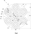
- This cable comprises an internal layer of the cable consisting of an internal strand and an external layer of the cable consisting of six external strands wound helically around the internal layer of the cable.
- Each internal and external strand comprises an internal layer of the strand consisting of a single internal wire, an intermediate layer consisting of six wires and an external layer of the strand consisting of eleven external wires.
- the intermediate and external layers of the internal strand are wound in the S direction around the internal and intermediate layers of the internal strand respectively.
- the middle and outer layers of each outer strand are wound in the Z direction around respectively the internal and intermediate layers of each external strand.
- the external strands are wound helically around the internal strand in a winding direction of the cable, this being the direction S.
- Each pitch p2, p2' of the intermediate layers of each internal and external strand is equal to 14 mm and each pitch p3, p3' of the outer layer of each inner and outer strand is equal to 20 mm.
- Another structural cable consisting of six external strands wound helically around the internal layer of the cable is disclosed in CN203373487 .
- the cable is of construction (1*0.29+6*0.26+12*0.24) + 6*(1*0.24+6*0.21+12*0.2) (-/6/10)(-/8/13)23, (-/s/s)(-/z/z)S resulting in a ratio (p3'-p2')/p3' of 0.385.
- Another solution to increase the life of the tire is to increase the breaking force of the cable.
- the breaking force is increased by increasing the diameter of the wires constituting the cable and/or the number of wires and/or the unit resistance of each wire.
- further increasing the diameter of the wires for example beyond 0.50 mm, necessarily leads to a reduction in the flexibility of the cable which is not desirable.
- Increasing the number of wires most of the time leads to a reduction in the penetrability of the strands due to the elastomer composition.
- increasing the unit resistance of each wire requires significant investment in wire manufacturing facilities.
- the object of the invention is a cable having improved penetrability of its external strands and better accessibility of the internal strand by the elastomer composition compared to the cable of the state of the art, thus making it possible to reduce entry and propagation. corrosive agents in and along the cable.
- the pitch of a strand represents the length of this strand, measured parallel to the axis of the cable, at the end of which the strand having this pitch makes a complete turn around said axis of the cable.
- the pitch of a wire represents the length of this wire, measured parallel to the axis of the strand in which it is located, at the end of which the wire having this pitch makes a complete turn around said axis of the strand.
- winding direction of a layer of strands or wires we mean the direction formed by the strands or wires relative to the axis of the cable or strand.
- the direction of winding is commonly designated by the letter either Z or S.
- the pitches, winding direction and diameters of the wires and strands are determined in accordance with the 2014 ASTM D2969-04 standard.
- a desaturated layer of strands is such that there is sufficient space between the strands to allow the passage of an elastomer composition.
- the outer layer of strands is desaturated which means that the outer strands do not touch each other and that there is sufficient space between two adjacent outer strands allowing the passage of an elastomer composition up to 'to the internal strand.
- the inter-strand distance of the outer layer of external strands defined, on a section of the cable perpendicular to the main axis of the cable, as the shortest distance which separates, on average, the circular envelopes in which two adjacent external strands are inscribed, is non-zero.
- the inter-strand distance from the outer layer of external strands is greater than or equal to 30 ⁇ m, more preferably greater than or equal to 40 ⁇ m and even more preferably greater than or equal to 50 ⁇ m.
- the inter-strand distance of the outer layer of outer strands is greater than or equal to 70 ⁇ m, preferably greater than or equal to 100 ⁇ m, more preferably greater than or equal to 150 ⁇ m and even more preferably greater or equal to 200 ⁇ m.
- the internal strand can be, in certain embodiments, two layers, that is to say that it only comprises two layers but does not only comprise one, nor three; and that in other embodiments, the internal strand can be three-layered, that is to say it comprises only three layers but does not comprise only two, nor four.
- the cable has two layers of strands, that is to say that it comprises an assembly consisting of two layers of strands, neither more nor less, that is to say that the assembly has two layers of strands, not one, not three, but only two.
- the outer layer of the cable is wrapped around the inner layer of the cable in contact with the inner layer of the cable.
- the cable according to the invention has improved penetrability compared to a cable whose ratio (p3'-p2')/p3' is outside the range of ratios in accordance with the invention, such as for example the cable of the examples of WO2015/090920 for which the ratio (p3'-p2')/p3' is equal to 0.30 and whose penetrability can be improved thanks to the invention.
- the inventors behind the invention hypothesize that this ratio makes it possible to obtain relatively large radial passage windows for the elastomer composition within each external strand.
- the radial passage windows are defined as being the intersection between on the one hand the space projected on a plane parallel to the main axis of the cable between two adjacent wires of the outer layer of an external strand and on the other hand the space projected on a plane parallel to the main axis of the cable between two adjacent wires of the intermediate layer of this external strand.
- Such a radial passage window is illustrated on the Figure 14 .
- the cable according to the invention has spaces between the external strands allowing the passage of the elastomer composition.
- the high penetrability of the external strands made possible by the ratio (p3'-p2')/p3' and the desaturation of the external layer of the cable allows the elastomer composition to penetrate on the one hand, between the external strands and, on the other hand, between the external strands and the internal strand.
- this characteristic allows the elastomer composition to infiltrate between the outer layers of the inner and outer strands so as to create a mattress of elastomer composition at least partially absorbing the radial component of the force between the inner strands. and external.
- the direction of winding of the cable opposite the directions of winding of each external layer of each internal and external strand allows better penetrability of the cable, in particular between the external strands.
- the inventors hypothesize that thanks to these winding directions, the external wires of the external strands cross the external wires of the internal strand forming a relatively point contact zone unlike the cables of the examples of WO2015/090920 in which the direction of winding of the cable is identical to the directions of winding of the external layers of each internal and external strand and in which the external wires of the external strands cross the external wires of the internal strand forming a less punctual contact zone and more linear, preventing the passage of the elastomer composition to the internal strand.
- each external strand has cylindrical layers.
- the internal strand has cylindrical layers whether this internal strand has two or three layers. It is recalled that such cylindrical layers are obtained when the different layers of a strand are wound at different pitches and/or when the directions of winding of these layers are distinct from one layer to another.
- a strand with cylindrical layers is very highly penetrable unlike a strand with compact layers in which the pitches of all the layers are equal and the directions of winding of all the layers are identical and has a much lower penetrability.
- the cable is devoid of any polymeric composition, in particular the cable is devoid of any sheath of any polymeric composition covering the internal strand.
- the cable is devoid of any elastomeric composition, in particular the cable is devoid of any sheath of any elastomeric composition covering the internal strand.
- the cable is metallic.
- metallic cable means a cable made up of wires consisting mainly (that is to say for more than 50% of these wires) or entirely (for 100% of the wires) of a metallic material.
- Such a metal cable is preferably implemented with a steel cable, more preferably steel pearlitic (or ferrito-pearlitic) carbon, hereinafter referred to as "carbon steel”, or even stainless steel (by definition, steel containing at least 11% chromium and at least 50% iron). But it is of course possible to use other steels or other alloys.
- its carbon content (% by weight of steel) is preferably between 0.4% and 1.2%, in particular between 0.5% and 1.1%; these contents represent a good compromise between the mechanical properties required for the tire and the feasibility of the wires.
- the metal or steel used can itself be coated with a metallic layer improving, for example, the processing properties of the metal cable and/or its constituent elements, or the usage properties of the cable and/or the tire themselves, such as adhesion properties, corrosion resistance or even resistance to aging.
- the steel used is covered with a layer of brass (Zn-Cu alloy) or zinc.
- the wires of the same layer of a predetermined strand all have substantially the same diameter.
- the external strands all have substantially the same diameter.
- each wire of each strand has a diameter ranging from 0.15 mm to 0.60 mm, preferably from 0.20 mm to 0.50 mm, more preferably from 0.25 mm to 0.45 mm and even more preferably from 0.28 mm to 0.42 mm.
- polymer composition or polymeric composition is meant that the composition comprises at least one polymer.
- a polymer may be a thermoplastic, for example a polyester or a polyamide, a thermosetting polymer, an elastomer, for example natural rubber, a thermoplastic elastomer or a mixture of these polymers.
- elastomer composition or elastomeric composition is meant that the composition comprises at least one elastomer or a rubber (the two terms being synonymous) and at least one other component.
- the elastomer composition also includes a vulcanization system, a filler. More preferably, the elastomer is diene.
- the external strands are wound helically around the internal strand at a pitch ranging from 40 mm to 100 mm and preferably ranging from 50 mm to 90 mm.
- steps p2' and p3' verify the relationship 0.40 ⁇ (p3'-p2')/p3'.
- steps p2' and p3' verify the relationship 0.43 ⁇ (p3'-p2')/p3' and even more preferably 0.45 ⁇ (p3'-p2')/p3'.
- the greater the ratio (p3'-p2')/p3' in other words the greater the difference between p3' and p2', the better the architectural stability of each external strand.
- steps p2' and p3' verify the relationship (p3'-p2')/p3' ⁇ 0.55 and preferably (p3'-p2')/p3' ⁇ 0.53.
- the dimension of the radial passage windows of the elastomer composition is maximum and makes it possible to optimize the penetrability of each external strand.
- the pitch p2' is such that 8 mm ⁇ p2' ⁇ 16 mm, preferably 8 mm ⁇ p2' ⁇ 14 mm and more preferably 8 mm ⁇ p2' ⁇ 12 mm.
- the pitch p3' is such that 10 mm ⁇ p3' ⁇ 40 mm, preferably 15 mm ⁇ p3' ⁇ 35 mm, more preferably 15 mm ⁇ p3' ⁇ 25 mm and even more preferably 17 mm ⁇ p3' ⁇ 23mm.
- Steps p2' and p3' in these preferential ranges make it possible to obtain a cable having mechanical properties compatible with pneumatic use, a cost and a relatively low linear mass of the cable.
- the diameter of a strand is the diameter of the smallest circle within which the strand is circumscribed.
- the internal strand TI has a diameter DI and each external strand TE has a diameter DE.
- DI/DE ⁇ 1.30 preferably DI/DE ⁇ 1.35 and more preferably DI/DE ⁇ 1.40.
- DI/DE ⁇ 1.70 preferably DI/DE ⁇ 1.65 and more preferably DI/DE ⁇ 1.60.
- DI/DE ⁇ 1.60 preferably DI/DE ⁇ 1.65 and more preferably DI/DE ⁇ 1.70.
- DI/DE ⁇ 2.0 preferably DI/DE ⁇ 1.95 and more preferably DI/DE ⁇ 1.90.
- DI/DE ⁇ 2.00 preferably DI/DE ⁇ 2.05 and more preferably DI/DE ⁇ 2.10.
- DI/DE ⁇ 2.50 preferably DI/DE ⁇ 2.45 and more preferably DI/DE ⁇ 2.40.
- each internal wire of the internal strand has a diameter d1 greater than or equal to the diameter d1' of each internal wire of each external strand, preferably each internal wire of the internal strand has a diameter d1 equal to the diameter d1' of each internal wire of each external strand.
- the same wire diameter is used on the internal layers of each internal and external strand, which limits the number of different wires to manage. during the manufacture of the cable.
- each internal wire of the internal strand has a diameter d1 greater than or equal to the diameter d2' of each intermediate wire of each external strand, preferably each internal wire of the internal strand has a diameter d1 greater than the diameter d2' of each intermediate wire of each external strand.
- each internal wire of the internal strand has a diameter d1 greater than or equal to the diameter d3' of each external wire of each external strand, preferably each internal wire of the internal strand has a diameter d1 greater than the diameter d3' of each external wire of each external strand.
- each external wire of the internal strand has a diameter d3 greater than or equal to the diameter d3' of each external wire of each external strand, preferably each external wire of the internal strand has a diameter d3 greater than the diameter d3' of each external wire of each external strand.
- each external wire of the internal strand can support the radial component of the force exerted by the external strands on the internal strand during traction of the cable.
- This characteristic d3>d3' makes it possible to restore or even improve the breaking force of the cable compared to a cable comprising an arch formed by the external strands or compared to a cable in which d3 ⁇ d3'.
- 1 ⁇ d3/d3' ⁇ 2 more preferably 1 ⁇ d3/d3' ⁇ 1.5 and even more preferably 1 ⁇ d3/d3' ⁇ 1.25 or 1.25 ⁇ d3/d3' ⁇ 1, 5.
- the outer layer of the cable is incompletely unsaturated.
- An incompletely unsaturated layer of strands is such that there is not enough space in this layer to add at least one (X+1)th strand of the same diameter as the X strands of the layer.
- the sum SIE of the interstrand distances E of the outer layer of the cable is such that SIE ⁇ DE.
- the sum SIE is the sum of the interstrand distances E separating each pair of adjacent strands of the layer.
- the inter-strand distance of a layer is defined, on a section of the cable perpendicular to the main axis of the cable, as the shortest distance which separates, on average, two adjacent strands of the layer.
- the interstrand distance E is calculated by dividing the sum SIE by the number of spaces separating the strands of the layer.
- the sum SI2' of the interwire distances of the intermediate layer of each external strand is such that SI2' ⁇ d3' with d3' being the diameter of each external wire of each external strand, preferably SI2' ⁇ 0.8 x d3 '.
- the sum SI2' is the sum of the inter-wire distances separating each pair of adjacent wires of the layer.
- the interwire distance of a layer is defined, on a section of the cable perpendicular to the main axis of the cable, as the shortest distance which separates, on average, two adjacent wires of the layer.
- the inter-wire distance is calculated by dividing the sum SI2' by the number of spaces separating the wires of the layer.
- the diameter d3' of the external wires of the external layer of each external strand being preferentially greater than the sum SI2', the external wires are prevented from penetrating into the intermediate layer. This ensures good architectural stability, which reduces the risk of modification of the radial passage windows of the elastomer composition and therefore the risk of degrading the good penetrability of each external strand.
- the intermediate layer of each external strand is desaturated, preferably incompletely unsaturated.
- a desaturated layer of wires is such that there is sufficient space between the wires to allow the passage of an elastomer composition.
- a desaturated layer means that the wires of this layer do not touch each other and that there is sufficient space between two adjacent wires of the layer allowing the passage of an elastomer composition through the layer, c that is to say that the inter-wire distance of the layer is non-zero.
- the interwire distance of the intermediate layer of each external strand is greater than or equal to 5 ⁇ m, more preferably greater than or equal to 10 ⁇ m, even more preferably greater than or equal to 20 ⁇ m and very preferably greater than or equal to 30 ⁇ m. In a very advantageous embodiment, the interwire distance of the intermediate layer of each external strand is greater than or equal to 35 ⁇ m, more preferably greater than or equal to 50 ⁇ m and even more preferably greater than or equal to 60 ⁇ m.
- the desaturation of the intermediate layer of each external strand advantageously makes it possible to facilitate the passage of the elastomer composition into and through each external strand.
- an incompletely unsaturated layer is such that there is not enough space in this layer to add at least one (P+1) th wire of the same diameter as the P wires of the layer.
- the sum SI2' of the interwire distances I2' of the intermediate layer C2' is less than the diameter d2' of the intermediate wires F2' of the intermediate layer C2'.
- each external strand comprises a relatively high number of intermediate wires and therefore has a relatively high breaking strength.
- the outer layer of each outer strand is desaturated, preferably completely unsaturated.
- the desaturation of the external layer of each external strand advantageously makes it possible to facilitate the passage of the elastomer composition into and through each external strand.
- a desaturated layer of wires is such that there is sufficient space between the wires to allow the passage of an elastomer composition.
- a desaturated layer means that the wires of this layer do not touch each other and that there is sufficient space between two adjacent wires of the layer allowing the passage of an elastomer composition through the layer, c that is to say that the inter-wire distance of the layer is non-zero.
- the interwire distance of the outer layer of each outer strand is greater than or equal to 5 ⁇ m, more preferably greater than or equal to 10 ⁇ m, even more preferably greater than or equal to 20 ⁇ m and very preferably greater than or equal to 30 ⁇ m. In a very advantageous embodiment, the interwire distance of the outer layer of each outer strand is greater than or equal to 35 ⁇ m, more preferably greater than or equal to 50 ⁇ m and even more preferably greater than or equal to 60 ⁇ m.
- a completely unsaturated layer is, as opposed to an incompletely unsaturated layer, such that there is sufficient space in this layer to add at least one (P+1) th wire of the same diameter as the P wires of the layer, several wires may then be in contact with each other or not.
- external layer of completely unsaturated external strand we mean that the sum SI3' of the interwire distances I3' of the external layer C3' is greater than the diameter d3' of the external wires F3' of the external layer C3'.
- the internal wire of each external strand has a diameter d1' greater than or equal to the diameter d3' of each external wire of each external strand, preferably the internal wire of each external strand has a diameter d1' greater to the diameter d3' of each external wire of each external strand.
- the use of diameters such as d1'>d3' makes it possible to promote the penetrability of the elastomer composition through the external layer.
- the internal wire of each external strand has a diameter d1' greater than or equal to the diameter d2' of each intermediate wire of each external strand, preferably each internal wire of each external strand has a diameter d1' greater than the diameter d2' of each intermediate wire of each external strand.
- the preferential use of diameters such as d1'>d2' makes it possible to promote the penetrability of the elastomer composition through the intermediate layer.
- Such an external strand has the advantages of architectural stability and penetrability presented above.
- the desaturation of the intermediate and outer layers, the incomplete saturation of the intermediate layer and the complete unsaturation of the outer layer are obtained by using different diameters of wires.
- each intermediate wire of each external strand having a diameter d2' and each external wire of each external strand having a diameter d3', d2' d3'.
- the same wire diameter is used on the intermediate and outer layers of each outer strand, which limits the number of different wires to manage during the manufacture of the cable.
- the outer layer of the internal strand is desaturated, preferably completely unsaturated. Desaturation of the outer layer of the inner strand advantageously makes it easier to pass the elastomer composition to the center of the internal strand.
- a desaturated layer of wires is such that there is sufficient space between the wires to allow the passage of an elastomer composition.
- a desaturated layer means that the wires of this layer do not touch each other and that there is sufficient space between two adjacent wires of the layer allowing the passage of an elastomer composition through the layer, c that is to say that the inter-wire distance of the layer is non-zero.
- the interwire distance of the outer layer of the internal strand is greater than or equal to 5 ⁇ m, more preferably greater than or equal to 10 ⁇ m, even more preferably greater than or equal to 20 ⁇ m and very preferably greater than or equal to 30 ⁇ m. In a very advantageous embodiment, the interwire distance of the outer layer of the internal strand is greater than or equal to 35 ⁇ m, more preferably greater than or equal to 50 ⁇ m and even more preferably greater than or equal to 60 ⁇ m.
- the outer layer of the internal strand is preferably completely unsaturated, that is to say that there is enough space in the outer layer to add at least one (N+1) th wire of the same diameter as the N wires of the outer layer.
- N+1 the sum SI3 of the interwire distances I3 of the external layer C3 is greater than the diameter d3 of the external wires F3 of the external layer C3.
- the complete unsaturation of the outer layer of the internal strand makes it possible to maximize the penetration of the elastomer composition into the internal strand.
- each internal wire of the internal strand has a diameter d1 greater than or equal to the diameter d3 of each external wire of the internal strand.
- the internal strand is two-layer.
- the outer layer of the inner strand is wound around the inner layer of the inner strand in contact with the inner layer of the inner strand.
- the inner strand comprises a wire assembly consisting of two layers of wires, neither more nor less, that is, the wire assembly has two layers of wires, not one, not three , but only two.
- Q>1, preferably Q 2, 3 or 4.
- Q the internal wire of the internal strand exits radially from the internal strand and even from the cable. Thanks to the presence of several wires in the internal layer of the internal strand (Q>1), this risk is reduced, the compressive forces then being distributed over the plurality of wires of the internal layer.
- each internal wire of the internal strand has a diameter d1 equal to the diameter d3 of each external wire of the internal strand.
- the same wire diameter is preferably used on the internal and external layers of the internal strand, which limits the number of different wires to manage during the manufacture of the cable.
- the intermediate layer of each external strand is wound around the internal layer of each external strand in a winding direction identical to the winding direction of the cable.
- the internal layer of the internal strand is wound helically in a winding direction identical to the winding direction of the cable.
- the internal layer of the internal strand is wound helically in a winding direction opposite to the winding direction of the cable.
- the intermediate layer of each outer strand is wound around the inner layer of each outer strand in a winding direction opposite to the winding direction of the cable.
- the internal layer of the internal strand is wound helically in a winding direction identical to the winding direction of the cable.
- the outer layer of the inner strand is wound around the middle layer of the inner strand in contact with the middle layer of the inner strand and the middle layer of the inner strand is wound around the inner layer of the inner strand in contact of the internal layer of the internal strand.
- the inner strand comprises a wire assembly consisting of three layers of wires, no more and no less, that is, the wire assembly has three layers of wires, not two, not four , but only three.
- the sum SI2 of the interwire distances of the intermediate layer is such that SI2 ⁇ d3 with d3 being the diameter of each external wire of the internal strand, preferably SI2 ⁇ 0.8 x d3.
- the diameter d3 of the external wires of the external layer of the internal strand being preferentially greater than the sum SI2, the external wires are prevented from penetrating into the intermediate layer. This ensures good architectural stability, which reduces the risk of modification of the radial passage windows of the elastomer composition and therefore the risk of degrading the good penetrability of the internal strand.
- the intermediate layer of the internal strand is desaturated, preferably incompletely unsaturated.
- a desaturated layer of wires is such that there is sufficient space between the wires to allow the passage of an elastomer composition.
- a desaturated layer means that the wires of this layer do not touch each other and that there is sufficient space between two adjacent wires of the layer allowing the passage of an elastomer composition through the layer, c that is to say that the inter-wire distance of the layer is non-zero.
- the interwire distance of the intermediate layer of the internal strand is greater than or equal to 5 ⁇ m, more preferably greater than or equal to 10 ⁇ m, even more preferably greater than or equal to 20 ⁇ m and very preferably greater than or equal to 30 ⁇ m. In a very advantageous embodiment, the interwire distance of the intermediate layer of the internal strand is greater than or equal to 35 ⁇ m, more preferably greater than or equal to 50 ⁇ m and even more preferably greater than or equal to 60 ⁇ m.
- the desaturation of the intermediate layer of the internal strand advantageously makes it possible to facilitate the passage of the elastomer composition to the center of the internal strand.
- the intermediate layer of the internal strand is preferably incompletely unsaturated, that is to say that there is not enough space in the intermediate layer to add at least one (M+1) th wire of the same diameter as the M middle layer son.
- incompletely unsaturated intermediate layer of the internal strand we mean that the sum SI2 of the interwire distances I2 of the intermediate layer C2 is less than the diameter d2 of the intermediate wires F2 of the intermediate layer C2.
- the incomplete unsaturation of the intermediate layer of the internal strand ensures architectural stability of the intermediate layer. Furthermore, the incomplete unsaturation of the intermediate layer of the internal strand ensures that the internal strand comprises a relatively high number of intermediate wires and therefore has a relatively high breaking force.
- each internal wire of the internal strand has a diameter d1 greater than the diameter d3 of each external wire of the internal strand.
- the use of diameters such as d1>d3 makes it possible to promote the penetrability of the elastomer composition through the external layer.
- each internal wire of the internal strand has a diameter d1 greater than or equal to the diameter d2 of each intermediate wire of the internal strand, preferably each internal wire of the internal strand has a diameter d1 greater than the diameter d2 of each wire intermediate of the internal strand.
- the preferential use of diameters such as d1>d2 makes it possible to promote the penetrability of the elastomer composition through the intermediate layer.
- Q 1, 2, 3 or 4
- Q 1.
- the composition of elastomer acts as a shrinking layer around the internal strand, in particular around the external and intermediate layers of the internal strand preventing the exit of the internal wire even under repeated compression forces.
- the M intermediate wires are wound around the internal layer with a pitch p2 and the N external wires are wound around the intermediate layer with a pitch p3, the steps p2 and p3 then verifying: 0.36 ⁇ (p3-p2)/p3 ⁇ 0.57.
- Such a ratio (p3-p2)/p3 makes it possible to obtain relatively large radial passage windows for the elastomer composition within the internal strand.
- steps p2 and p3 verify 0.38 ⁇ (p3-p2)/p3, preferably 0.40 ⁇ (p3-p2)/p3, more preferably 0.43 ⁇ (p3-p2)/p3 and even more preferably 0.45 ⁇ (p3-p2)/p3.
- steps p2 and p3 verify (p3-p2)/p3 ⁇ 0.55 and preferably (p3-p2)/p3 ⁇ 0.53.
- the dimension of the radial passage windows of the elastomer composition is maximum and makes it possible to optimize the penetrability of the internal strand.
- the pitch p2 is such that 8 mm ⁇ p2 ⁇ 16 mm, preferably 8 mm ⁇ p2 ⁇ 14 mm and more preferably 8 mm ⁇ p2 ⁇ 12 mm.
- the pitch p3 is such that 10 mm ⁇ p3 ⁇ 40 mm, preferably 15 mm ⁇ p3 ⁇ 35 mm, more preferably 15 mm ⁇ p3 ⁇ 25 mm and even more preferably 17 mm ⁇ p3 ⁇ 23 mm.
- Steps p2 and p3 in these preferential ranges make it possible to obtain a cable having mechanical properties compatible with pneumatic use, a cost and a relatively low linear mass of the cable.
- Such an internal strand has the advantages of architectural stability and penetrability presented above.
- the desaturation of the intermediate and outer layers, the incomplete saturation of the intermediate layer and the complete unsaturation of the outer layer are obtained by using different diameters of wires.
- the elastomer composition prevents corrosive agents from accessing the central capillary, and in the best case where the central capillary is itself penetrated, the propagation of these corrosive agents along the cable.
- Such an internal strand has the advantages of architectural stability and penetrability presented above.
- the desaturation of the intermediate and outer layers, the incomplete saturation of the intermediate layer and the complete unsaturation of the outer layer are obtained by using different diameters of wires.
- each intermediate wire of the internal strand having a diameter d2 and each external wire of the internal strand having a diameter d3, d2 d3.
- the same wire diameter is used on the intermediate and outer layers of the internal strand, which limits the number of different wires to manage during the manufacture of the cable.
- each intermediate wire of the internal strand has a diameter d2 greater than or equal to the diameter d2' of each intermediate wire of each external strand, preferably each intermediate wire of the internal strand has a diameter d2 greater than the diameter d2' of each intermediate wire of each external strand.
- the intermediate layer of each external strand is wound around the internal layer of each external strand in a winding direction identical to the winding direction of the cable.
- the intermediate layer of the internal strand is wound around the internal layer of the internal strand in a winding direction identical to the winding direction of the cable.
- the intermediate layer of the internal strand is wound around the internal layer of the internal strand in a direction of winding opposite to the direction of winding of the cable.
- the internal layer of the internal strand is wound helically in a winding direction identical to the winding direction of the cable or, alternatively, in a direction of winding opposite to the direction of winding of the cable.
- the intermediate layer of each outer strand is wound around the inner layer of each outer strand in a winding direction opposite to the winding direction of the cable.
- the intermediate layer of the internal strand is wound around the internal layer of the internal strand in a winding direction identical to the winding direction of the cable.
- the intermediate layer of the internal strand is wound around the internal layer of the internal strand in a direction of winding opposite to the direction of winding of the cable.
- the friction of the wires of the adjacent layers and therefore their wear is limited.
- the internal layer of the internal strand is wound helically in a winding direction identical to the winding direction of the cable or, alternatively, in a direction of winding opposite to the direction of winding of the cable.
- the internal strand is of the gummed in situ type.
- a strand comprises, before assembling the cable, a layer of a polymer composition, in particular an elastomer composition arranged between at least two layers of radially adjacent wires, optionally between each layer of radially adjacent wires.
- a gummed strand in situ is notably described in WO2010/054790 .
- the internal strand is of the type not gummed in situ.
- the internal strand is made up of the wires of the different layers and devoid of polymer composition, in particular elastomer composition.
- Another object of the invention is a tire comprising at least one cable as defined above.
- the tire comprises a carcass reinforcement anchored in two beads and surmounted radially by a crown reinforcement itself surmounted by a tread, the crown reinforcement being joined to said beads by two sidewalls and comprising at least one cable as defined above.
- the top frame comprises a protective frame and a working frame, the working frame comprising at least one cable as defined above, the protective frame being radially interposed between the tread and working frame.
- the cable is particularly intended for industrial vehicles chosen from heavy vehicles such as "heavy goods vehicles” - ie, metro, bus, road transport vehicles (trucks, tractors, trailers), off-road vehicles -, agricultural machinery or civil engineering, other transport or handling vehicles.
- heavy vehicles such as "heavy goods vehicles” - ie, metro, bus, road transport vehicles (trucks, tractors, trailers), off-road vehicles -, agricultural machinery or civil engineering, other transport or handling vehicles.
- the tire is for a civil engineering type vehicle.
- the tire has a dimension in which the diameter, in inches, of the seat of the rim on which the tire is intended to be mounted is greater than or equal to 40 inches.
- any interval of values designated by the expression “between a and b” represents the range of values going from more than a to less than b (that is to say limits a and b excluded) while any interval of values designated by the expression “from a to b” means the range of values going from terminal “a” to terminal “b”, that is to say including the strict limits “a” and “b”.
- a reference mark X, Y, Z is shown corresponding to the usual respectively axial (X), radial (Y) and circumferential (Z) orientations of a tire.
- the “median circumferential plane” M of the tire is the plane which is normal to the axis of rotation of the tire and which is located equidistant from the annular reinforcing structures of each bead.
- the tire 10 is for heavy civil engineering type vehicles, for example of the “dumper” type.
- the tire 10 has a dimension of type 53/80R63.
- the tire 10 comprises a crown 12 reinforced by a crown reinforcement 14, two sidewalls 16 and two beads 18, each of these beads 18 being reinforced with an annular structure, here a rod 20.
- the crown reinforcement 14 is surmounted radially by a tread 22 and joined to the beads 18 by the sidewalls 16.
- a carcass reinforcement 24 is anchored in the two beads 18, and is here wound around the two rods 20 and includes a turnaround 26 disposed towards the outside of the tire 20 which is shown here mounted on a rim 28.
- the carcass reinforcement 24 is surmounted radially by the crown reinforcement 14.
- the carcass reinforcement 24 comprises at least one carcass ply 30 reinforced by radial carcass cables (not shown).
- the carcass cables are arranged substantially parallel to each other and extend from a bead 18 to the other so as to form an angle between 80° and 90° with the median circumferential plane M (plane perpendicular to the axis of rotation of the tire which is located halfway between the two beads 18 and passes through the middle of the top frame 14).
- the tire 10 also comprises a sealing ply 32 made of an elastomer (commonly called inner rubber) which defines the radially internal face 34 of the tire 10 and which is intended to protect the carcass ply 30 from the diffusion of air coming from of the interior space of the tire 10.
- a sealing ply 32 made of an elastomer (commonly called inner rubber) which defines the radially internal face 34 of the tire 10 and which is intended to protect the carcass ply 30 from the diffusion of air coming from of the interior space of the tire 10.
- the crown reinforcement 14 comprises, radially from the outside towards the inside of the tire 10, a protective reinforcement 36 arranged radially inside the tread 22, a working reinforcement 38 arranged radially inside of the protective frame 36 and an additional frame 40 arranged radially inside the working frame 38.
- the protective frame 36 is thus radially interposed between the tread 22 and the working frame 38.
- the working frame 38 is radially interposed between the protective frame 36 and the additional frame 40.
- the protective frame 36 comprises first and second protective layers 42, 44 comprising metallic protective cables, the first layer 42 being arranged radially inside the second layer 44.
- the metallic protective cables make an angle at least equal to 10°, preferably ranging from 10° to 35° and preferably from 15° to 30° with the circumferential direction Z of the tire.
- the working frame 38 comprises first and second working layers 46, 48, the first layer 46 being arranged radially inside the second layer 48.
- Each layer 46, 48 comprises at least one cable 50.
- the metal working cables 50 are crossed from one working ply to the other and make an angle at most equal to 60°, preferably ranging from 15° to 40° with the circumferential direction Z of the tire.
- the additional reinforcement 40 also called a limiter block, whose function is to partially absorb the mechanical inflation stresses, comprises, for example and in a manner known per se, additional metallic reinforcing elements, for example as described in FR 2 419 181 Or FR 2 419 182 making an angle at most equal to 10°, preferably ranging from 5° to 10° with the circumferential direction Z of the tire 10.
- the cable 50 is metallic and is of the multi-strand type with two cylindrical layers. Thus, we understand that the layers of strands constituting the cable 50 are at number of two, no more, no less. The layers of strands are adjacent and concentric.
- the cable 50 is devoid of polymeric composition and elastomer composition when it is not integrated into the tire.
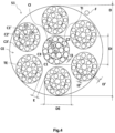
- the cable 50 comprises an internal layer CI of the cable 50 as well as an external layer CE of the cable 50.
- the internal layer CI consists of a single internal strand TI.
- the cable 50 also includes a hoop F consisting of a single hoop wire.
- the internal TI strand has an infinite pitch.
- the outer layer CE is wound around the inner layer CI in a winding direction of the cable, here the direction S.
- the outer strands TE are wound helically around the inner strand TI at a pitch p such that 40 mm ⁇ p ⁇ 100 mm and preferably 50 mm ⁇ p ⁇ 90 mm.
- p 70 mm.
- the hoop F is wound around the outer layer CE in a direction of winding of the hoop, here opposite to the direction of winding of the cable, in this case in the direction Z.
- the hoop wire is wound helically around the external TE strands with a pitch pf such as 2 mm ⁇ pf ⁇ 10 mm and preferably 3 mm ⁇ pf ⁇ 8 mm.
- pf 5.1 mm.
- the assembly constituted by the internal layers CI and external CE, that is to say the cable 50 without the hoop F, has a diameter D greater than or equal to 4 mm and less than or equal to 6 mm, preferably 5 mm and more preferably at 4.3 mm.
- D 4.9 mm.
- the outer CE layer of cable 50 is desaturated.
- the average inter-strand distance E separating two adjacent external strands TE is greater than or equal to 30 ⁇ m, more preferably greater than or equal to 40 ⁇ m and even more preferably greater than or equal to 50 ⁇ m.
- the inter-strand distance of the outer layer of outer strands is greater than or equal to 70 ⁇ m.
- E 87.3 ⁇ m.
- the internal strand TI has a diameter DI and each external strand TE has a diameter DE such that the ratio DI/DE>1, preferably DI/DE ⁇ 1.05 and more preferably DI/DE ⁇ 1.10.
- the TI internal strand has at least two layers. In this case, the internal TI strand has three layers.
- the internal TI strand includes, here is made up of three layers, not more, not less.
- the internal strand TI comprises an internal layer C1 made up of Q internal wire(s) F1, an intermediate layer C2 made up of M intermediate wires F2 wound helically around the internal layer C1 and an external layer C3 made up of N wires external F3 wound helically around the internal layer C1 and around and in contact with the intermediate layer C2.
- the internal wire F1 has an infinite pitch.
- the intermediate layer C2 of the internal strand TI is wound around the internal layer C1 of the internal strand TI in a direction of winding Z opposite to the direction of winding of the cable S.
- the M intermediate wires F2 are wound helically around the internal wire F1 according to a pitch p2 such that 8 mm ⁇ p2 ⁇ 16 mm, preferably 8 mm ⁇ p2 ⁇ 14 mm.
- p2 14 mm.
- the outer layer C3 of the inner strand TI is wound around the inner C1 and intermediate layers C2 of the inner strand TI in a winding direction Z opposite to the winding direction of the cable S and in the same direction Z as the intermediate layer C2 of the TI internal strand.
- the N external wires F3 are wound helically around the M intermediate wires F2 at a pitch p3 such that 10 mm ⁇ p3 ⁇ 40 mm, preferably 15 mm ⁇ p3 ⁇ 35 mm, more preferably 15 mm ⁇ p3 ⁇ 25 mm and again more preferably 17 mm ⁇ p3 ⁇ 23 mm.
- p3 20 mm.
- the intermediate layer C2 of the internal strand TI is desaturated and incompletely unsaturated.
- the interwire distance I2 of the intermediate layer C2 separating on average the M intermediate wires is greater than or equal to 5 ⁇ m.
- the interwire distance I2 is preferably greater than or equal to 10 ⁇ m and here equal to 11.6 ⁇ m.
- the intermediate layer C2 being incompletely unsaturated, the sum SI2 of the interwire distances I2 of the intermediate layer C2 is less than the diameter d2 of the intermediate wires F2 of the intermediate layer C2.
- the sum SI2 of the interwire distances I2 of the intermediate layer C2 is less than the diameter d3 of the external wires F3 of the external layer C3 and preferably less than or equal to 0.8 x d3.
- the outer layer C3 of the inner strand TI is desaturated and completely unsaturated.
- the interwire distance I3 of the external layer C3 separating on average the N external wires is greater than or equal to 5 ⁇ m.
- the interwire distance I3 is preferably greater than or equal to 10 ⁇ m, more preferably greater than or equal to 20 ⁇ m and even more preferably 30 ⁇ m. In this embodiment, the interwire distance I3 is preferably greater than or equal to 35 ⁇ m and here equal to 45 ⁇ m.
- the sum SI3 of the interwire distances I3 of the external layer C3 is greater than the diameter d3 of the external wires F3 of the external layer C3.
- Each internal, intermediate and external wire of the internal strand TI has a diameter d1, d2 and d3 respectively.
- Each diameter of the internal d1, intermediate d2 and external d3 wires of the internal strand TI ranges from 0.15 mm to 0.60 mm, preferably from 0.20 mm to 0.50 mm, more preferably from 0.25 mm to 0 .45 mm and even more preferably from 0.28 mm to 0.42 mm.
- the internal wire F1 of the internal strand TI has a diameter d1 greater than or equal to the diameter d2 of each intermediate wire F2 of the internal strand TI.
- the internal wire F1 of the internal strand TI has a diameter d1 greater than or equal to the diameter d3 of each external wire F3 of the internal strand TI.
- each TE outer strand is three-layered.
- each external TE strand includes, here is made up of, three layers, no more, no less.
- the internal wire F1' has an infinite pitch.
- the intermediate layer C2' of each external strand TE is wound around the internal layer C1' of each external strand TE in a winding direction Z opposite to the winding direction S of the cable.
- the M' intermediate wires F2' are wound helically around the internal wire(s) F1' at a pitch p2' such that 8 mm ⁇ p2' ⁇ 16 mm, preferably 8 mm ⁇ p2' ⁇ 14 mm and more preferably 8 mm ⁇ p2' ⁇ 12 mm.
- p2' 10 mm.
- the outer layer C3' of each outer strand TE is wound around the intermediate layer C2' of each outer strand TE in a winding direction Z opposite to the winding direction S of the cable and in the same direction Z as the intermediate layer C2' of each external strand TE and in the same direction Z as the external layer C3 of the internal strand TI.
- the N' external wires F3' are wound helically around the M' intermediate wires F2' according to a pitch p3' such that 10 mm ⁇ p3' ⁇ 40 mm, preferably 15 mm ⁇ p3' ⁇ 35 mm, more preferably 15 mm ⁇ p3' ⁇ 25 mm and even more preferably 17 mm ⁇ p3' ⁇ 23 mm.
- p3' 20 mm.
- Steps p2' and p3' verify 0.40 ⁇ (p3'-p2')/p3' ⁇ 0.57.
- 0.43 ⁇ (p3'-p2')/p3' more preferably 0.45 ⁇ ( p3'-p2')/p3'.
- the intermediate layer C2' of each external strand TE is desaturated and incompletely unsaturated.
- the interwire distance I2' of the intermediate layer C2' separating on average the M' intermediate wires is greater than or equal to 5 ⁇ m.
- the interwire distance I2' is preferably greater than or equal to 10 ⁇ m, more preferably greater than or equal to 20 ⁇ m and even more preferably 30 ⁇ m. In this embodiment, the interwire distance I2' is preferably greater than or equal to 35 ⁇ m and here equal to 35.4 ⁇ m.
- the sum SI2' of the interwire distances I2' of the intermediate layer C2' is less than the diameter d2' of the intermediate wires F2' of the intermediate layer C2'.
- the sum SI2' of the interwire distances I2' of the intermediate layer C2' is less than the diameter d3' of the external wires F3' of the external layer C3' and preferably less than or equal to 0.8 x d3'.
- the outer layer C3' of each outer strand TE is desaturated and completely unsaturated.
- the interwire distance I3' of the external layer C3' separating on average the N' external wires is greater than or equal to 5 ⁇ m.
- the interwire distance I3' is preferably greater than or equal to 10 ⁇ m, more preferably greater than or equal to 20 ⁇ m and even more preferably 30 ⁇ m.
- the interwire distance I3' is preferably greater than or equal to 35 ⁇ m and more preferably greater than or equal to 50 ⁇ m and here equal to 55.4 ⁇ m.
- the sum SI3' of the interwire distances I3' of the external layer C3' is greater than the diameter d3' of the external wires F3' of the external layer C3'.
- Each internal, intermediate and external wire of each external TE strand has a diameter d1', d2' and d3' respectively.
- Each diameter of the internal d1', intermediate d2' and external d3' wires of the internal strand TI ranges from 0.15 mm to 0.60 mm, preferably from 0.20 mm to 0.50 mm, more preferably from 0.25 mm to 0.45 mm and even more preferably from 0.28 mm to 0.42 mm.
- the internal wire F1' of each external strand TE has a greater diameter d1' or equal to the diameter d2' of each intermediate wire F2' of each external strand TE.
- the internal wire F1' of each external strand TE has a diameter d1' greater than or equal to the diameter d3' of each external wire F3' of each external strand TE.
- Each internal wire F1 of the internal strand TI has a diameter d1 greater than or equal to the diameter d1' of each internal wire F1' of each external strand TE, preferably each internal wire F1 of the internal strand TI has a diameter d1 equal to the diameter d1' of each internal wire F1' of each external strand TE.
- Each internal wire F1 of the internal strand TI has a diameter d1 greater than or equal to the diameter d2' of each intermediate wire F2' of each external strand TE, preferably each internal wire F1 of the internal strand TI has a diameter d1 greater than the diameter d2' of each intermediate wire F2' of each external strand TE.
- Each internal wire F1 of the internal strand TI has a diameter d1 greater than or equal to the diameter d3' of each external wire F3' of each external strand TE, preferably each internal wire F1 of the internal strand TI has a diameter d1 greater than the diameter d3' of each external wire F3' of each external strand TE.
- Each intermediate wire F2 of the internal strand TI has a diameter d2 greater than or equal to the diameter d2' of each intermediate wire F2' of each external strand TE.
- Each external wire F3 of the internal strand TI has a diameter d3 greater than or equal to the diameter d3' of each external wire F3 of each external strand TE.
- Each wire has a breaking strength, noted Rm, such that 2500 ⁇ Rm ⁇ 3100 MPa.
- the steel of these wires is said to be SHT (“Super High Tensile”) grade.
- Other yarns can be used, for example yarns of a lower grade, for example of grade NT (“Normal Tensile”) or HT (“High Tensile”), as well as yarns of a higher grade, for example of grade UT (“ Ultra Tensile”) or MT (“Mega Tensile”).
- torque balancing we mean here in a manner well known to those skilled in the art the cancellation of the residual torques (or the elastic return of torsion) exerted on each wire of the strand, in the intermediate layer as in the outer layer.
- each strand is wound on one or more receiving reels, for storage, before the subsequent operation of wiring assembly of the elementary strands to obtain the multi-strand cable.
- the cable is then incorporated by calendering into composite fabrics formed from a known composition based on natural rubber and carbon black as a reinforcing filler, conventionally used for the manufacture of crown reinforcements of radial tires.
- This composition essentially comprises, in addition to the elastomer and the reinforcing filler (carbon black), an antioxidant, stearic acid, an extension oil, cobalt naphthenate as an adhesion promoter, finally a vulcanization system (sulfur, accelerator, ZnO).
- the composite fabrics reinforced by these cables comprise a matrix of elastomeric composition formed of two thin layers of elastomeric composition which are superimposed on either side of the cables and which respectively have a thickness of between 1 and 4 mm inclusive.
- the calendering pitch (no laying of the cables in the elastomeric composition fabric) ranges from 4 mm to 8 mm.
- the interwire distance I3 of the external layer C3 separating on average the N external wires is equal to 12 ⁇ m.
- the sum SI3 of the interwire distances I3 of the external layer C3 is less than the diameter d3 of the external wires F3 of the external layer C3.
- the outer layer C3' of each outer strand TE is desaturated, here completely unsaturated.
- the interwire distance I3' of the external layer C3' separating on average the N' external wires is equal to 25.7 ⁇ m.
- the sum SI3' of the interwire distances I3' of the external layer C3' is greater than the diameter d3' of the external wires F3' of the external layer C3'.
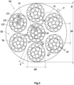
- the internal strand of the cable 52 according to the third embodiment is identical to the internal strand of the cable 50 according to the first embodiment.
- the intermediate layer C2' of each external strand TE is desaturated and incompletely unsaturated.
- the interwire distance I2' of the intermediate layer C2' separating on average the M' intermediate wires is equal to 57.5 ⁇ m.
- the sum SI2' of the interwire distances I2' of the intermediate layer C2' is less than the diameter d3' of the external wires F3' of the external layer C3' and preferably less than or equal to 0.8 x d3'.
- the outer layer C3' of each outer strand TE is desaturated and completely unsaturated.
- the interwire distance I3' of the external layer C3' separating on average the N' external wires is equal to 74.7 ⁇ m.
- the sum SI3' of the interwire distances I3' of the external layer C3' is greater than the diameter d3' of the external wires F3' of the external layer C3'.
- the internal wire F1' of each external strand TE has a diameter d1' equal to the diameter d2' of each intermediate wire F2' of each external strand TE.
- the internal wire F1' of each external strand TE has a diameter d1' greater than the diameter d3' of each external wire F3' of each external strand TE.
- Each diameter d2' of each intermediate wire F2' of each external strand TE and each diameter d3' of each external wire F3' of each external strand TE are such that d2'>d3'.
- Each intermediate wire F2 of the internal strand TI has a diameter d2 equal to the diameter d2' of each intermediate wire F2' of each external strand TE.
- each internal wire F1 of the internal strand TI of the cable 52 according to the third embodiment has a diameter d1 greater than or equal to the diameter d1' of each internal wire F1' of each strand external TE.
- each internal wire F1 of the internal strand TI has a diameter d1 greater than the diameter d1' of each internal wire F1' of each external strand TE.
- the assembly constituted by the internal CI and external CE layers, that is to say the cable 53 without the hoop F, has a diameter D 4.7 mm.
- the diameter DI of the internal strand TI and the diameter DE of each external strand TE are such that the ratio DI/DE ⁇ 1.30, preferably DI/DE ⁇ 1.35 and more preferably DI/DE ⁇ 1.40.
- This DI/DE ratio is also such that DI/DE ⁇ 1.70, preferably DI/DE ⁇ 1.65 and more preferably DI/DE ⁇ 1.60.
- DI 2.01 mm
- DE 1.36 mm
- DI/DE 1.48.
- the intermediate layer C2 of the internal strand TI is saturated.
- the interwire distance I2 of the intermediate layer C2 separating on average the M intermediate wires is equal to 0 ⁇ m.
- the interwire distance I3 of the external layer C3 separating on average the N external wires is less than 5 ⁇ m. Here, it is equal to 4.9 ⁇ m.
- the intermediate layer C2' of each external strand TE is desaturated and incompletely unsaturated.
- the interwire distance I2' of the intermediate layer C2' separating on average the M' intermediate wires is equal to 27.1 ⁇ m.
- the sum SI2' of the interwire distances I2' of the intermediate layer C2' is less than the diameter d3' of the external wires F3' of the external layer C3' and preferably less than or equal to 0.8 x d3'.
- the outer layer C3' of each outer strand TE is desaturated and completely unsaturated.
- the interwire distance I3' of the external layer C3' separating on average the N' external wires is equal to 46.6 ⁇ m.
- the sum SI3' of the interwire distances I3' of the external layer C3' is greater than the diameter d3' of the external wires F3' of the external layer C3'.
- the internal layer C1 of the internal strand TI is wound in a winding direction Z opposite to the winding direction S of the cable. Alternatively, this direction could be identical to the direction of the winding direction S of the cable.
- the intermediate layer C2 of the internal strand TI is desaturated and completely unsaturated.
- the interwire distance I2 of the intermediate layer C2 separating on average the M intermediate wires is equal to 14.6 ⁇ m.
- the sum SI2 of the interwire distances I2 of the intermediate layer C2 is less than the diameter d3 of the external wires F3 of the external layer C3 and preferably less than or equal to 0.8 x d3.
- the interwire distance I3 of the external layer C3 separating on average the N external wires is equal to 7 ⁇ m.
- the intermediate layer C2' of each external strand TE is desaturated and incompletely unsaturated.
- the interwire distance I2' of the intermediate layer C2' separating on average the M' intermediate wires is equal to 25.7 ⁇ m.
- the sum SI2' of the interwire distances I2' of the intermediate layer C2' is less than the diameter d3' of the external wires F3' of the external layer C3' and preferably less than or equal to 0.8 x d3'.
- the outer layer C3' of each outer strand TE is desaturated and completely unsaturated.
- the interwire distance I3' of the external layer C3' separating on average the N' external wires is equal to 57.5 ⁇ m.
- the sum SI3' of the interwire distances I3' of the external layer C3' is greater than the diameter d3' of the external wires F3' of the external layer C3'.
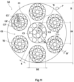
- the cable 55 according to the sixth embodiment differs from the cable 50 according to the first embodiment by its internal strand TI.
- the internal strand TI of the cable 55 is such that the steps p2 and p3 verify 0.36 ⁇ (p3-p2)/p3 ⁇ 0, 57.
- steps p2 and p3 verify 0.38 ⁇ (p3-p2)/p3, preferably 0.40 ⁇ (p3-p2)/p3, more preferably 0.43 ⁇ (p3-p2)/p3 and even more preferably 0.45 ⁇ (p3-p2)/p3.
- steps p2 and p3 also verify (p3-p2)/p3 ⁇ 0.55 and preferably (p3-p2)/p3 ⁇ 0.53.
- the interwire distance I2 of the intermediate layer C2 separating on average the M intermediate wires is equal to 8.2 ⁇ m.
- the outer layer C3 of the internal strand is desaturated and completely unsaturated.
- the interwire distance I3 of the external layer C3 separating on average the N external wires is equal to 45 ⁇ m.
- the sum SI3 of the interwire distances I3 of the external layer C3 is greater than the diameter d3 of the external wires F3 of the external layer C3.
- the intermediate layer C2 of the internal strand TI is desaturated and incompletely unsaturated.
- the interwire distance I2 of the intermediate layer C2 separating on average the M intermediate wires is equal to 39.1 ⁇ m.
- the sum SI2 of the interwire distances I2 of the intermediate layer C2 is less than the diameter d3 of the external wires F3 of the external layer C3 and preferably less than or equal to 0.8 x d3.
- the external layer C3 of the internal strand TI is desaturated and completely unsaturated.
- the interwire distance I3 of the external layer C3 separating on average the N external wires is equal to 107.2 ⁇ m.
- the sum SI3 of the interwire distances I3 of the external layer C3 is greater than the diameter d3 of the external wires F3 of the external layer C3.
- each external strand TE of the cable 56 according to the seventh embodiment is such that the M intermediate wires F2' are wound helically around the internal wire F1' at a pitch p2 ' such that 8 mm ⁇ p2' ⁇ 16 mm, preferably 8 mm ⁇ p2' ⁇ 14 mm.
- p2' 12.5 mm.
- d1' 0.45 mm
- the intermediate layer C2' of each external strand TE is desaturated and incompletely unsaturated.
- the interwire distance I2' of the intermediate layer C2' separating on average the M' intermediate wires is equal to 29.1 ⁇ m.
- the sum SI2' of the interwire distances I2' of the intermediate layer C2' is less than the diameter d3' of the external wires F3' of the external layer C3' and preferably less than or equal to 0.8 x d3'.
- the outer layer C3' of each outer strand TE is desaturated and completely unsaturated.
- the interwire distance I3' of the external layer C3' separating on average the N' external wires is equal to 61.3 ⁇ m.
- the sum SI3' of the interwire distances I3' of the external layer C3' is greater than the diameter d3' of the external wires F3' of the external layer C3'.
- each intermediate wire F2 of the internal strand TI has a diameter d2 greater than or equal to the diameter d2' of each intermediate wire F2' of each external strand TE.
- each external wire F3 of the internal strand TI has a diameter d3 greater than or equal to the diameter d3' of each external wire F3 of each external strand TE.
- a cable 57 according to an eighth embodiment of the invention We represented on the Figure 10 a cable 57 according to an eighth embodiment of the invention. Elements similar to the first embodiment are designated by identical references. Unless otherwise stated, only the differences compared to the first embodiment are described.
- the cable 57 according to the eighth embodiment differs from the cable 50 according to the first embodiment by its internal strand TI.
- the internal strand TI has two layers.
- the internal TI strand includes, here is made up of, two layers, no more, no less.
- the internal strand TI comprises an internal layer C1 consisting of Q internal wire(s) F1, and an external layer C3 consisting of N external wires F3 wound helically around and in contact with the internal layer C1.
- the internal layer C1 of the internal strand TI is wound helically in a winding direction Z opposite to the winding direction of the cable S.
- the outer layer C3 of the inner strand TI is wound around the inner layer C1 of the inner strand TI in a winding direction Z opposite to the winding direction of the cable S and in the same direction Z as the inner layer C1 of the inner strand IT.
- the N external wires F3 are wound helically around the internal wires F1 at a pitch p3 such that 10 mm ⁇ p3 ⁇ 40 mm, preferably 15 mm ⁇ p3 ⁇ 35 mm and more preferably 15 mm ⁇ p3 ⁇ 25 mm.
- p3 15.4 mm.
- the outer layer C3 of the inner strand TI is desaturated and completely unsaturated.
- the interwire distance I3 of the external layer C3 separating on average the N external wires is equal to 124.2 ⁇ m.
- the sum SI3 of the interwire distances I3 of the external layer C3 is greater than the diameter d3 of the external wires F3 of the external layer C3.
- a cable 58 according to a ninth embodiment of the invention Elements similar to the eighth embodiment are designated by identical references. Unless otherwise stated, only the differences with respect to the eighth embodiment are described.
- the cable 58 according to the ninth embodiment differs from the cable 57 according to the eighth embodiment by its internal strand TI.
- the outer layer C3 of the inner strand TI is desaturated and completely unsaturated.
- the interwire distance I3 of the external layer C3 separating on average the N external wires is equal to 75.8 ⁇ m.
- the sum SI3 of the interwire distances I3 of the external layer C3 is greater than the diameter d3 of the external wires F3 of the external layer C3.
- Cable 59 according to a tenth embodiment of the invention differs from the cable 50 according to the eighth embodiment due to its internal strand TI.
- the outer layer C3 of the inner strand TI is desaturated and completely unsaturated.
- the interwire distance I3 of the external layer C3 separating on average the N external wires is equal to 56.4 ⁇ m.
- the sum SI3 of the interwire distances I3 of the external layer C3 is greater than the diameter d3 of the external wires F3 of the external layer C3.
- Such a permeability test is well known to those skilled in the art and makes it possible to determine the longitudinal air permeability of the cables tested, by measuring the volume of air passing through a test piece under constant pressure for a given time.
- the principle of such a test is to demonstrate the effectiveness of treating a cable to make it airtight; it was described for example in standard ASTM D2692-98.
- Such a test is carried out on cables from manufacturing and not aged.
- the raw cables are previously coated from the outside with an elastomeric composition called coating.
- coating an elastomeric composition
- a series of 10 cables arranged in parallel (inter-cable distance: 20 mm) is placed between two layers or “skims" (two rectangles of 80 x 200 mm) of a diene elastomeric composition in the raw state.
- each skim having a thickness of 5 mm; the whole is then blocked in a mold, each of the cables being maintained under sufficient tension (for example 3 daN) to guarantee its straightness when placed in the mold, using clamping modules; then vulcanization (cooking) is carried out for approximately 10 to 12 hours at a temperature of approximately 120°C and under a pressure of 15 bar (rectangular piston of 80 x 200 mm). After which, the assembly is unmolded and 10 test pieces of cables coated in this way are cut, in the form of parallelepipeds measuring 7x7x60 mm, for characterization.
- sufficient tension for example 3 daN
- vulcanization cooking
- elastomeric coating composition a composition of conventional diene elastomer(s) for tires is used, based on natural rubber (peptized) and carbon black N330 (65 phr), further comprising the following usual additives : sulfur (7 pce), sulfenamide accelerator (1 pce), ZnO (8 pce), stearic acid (0.7 pce), antioxidant (1.5 pce), cobalt naphthenate (1.5 pce) (pce meaning parts by weight per hundred parts of elastomer); the modulus E10 of the elastomeric coating composition is approximately 10 MPa.
- the test is carried out on a 6 cm length of cable, therefore coated with its surrounding elastomeric composition (or elastomeric coating composition) in the cooked state, in the following way: air is sent to the entrance of the cable , under a pressure of 1 bar, and the volume of air at the outlet is measured, using a flow meter (calibrated for example from 0 to 500 cm 3 /min). During the measurement, the cable sample is clamped in a compressed airtight seal (e.g.
- a dense foam or rubber seal such that only the amount of air passing through the cable from one end to the other, along its longitudinal axis, is taken into account by the measurement; the tightness of the waterproof seal itself is checked beforehand using a test piece of solid elastomeric composition, that is to say without cable.
- the average air flow measured (average over the 10 test specimens) is all the lower as the longitudinal impermeability of the cable is high.
- the measurement being made with an accuracy of ⁇ 0.2 cm3/min, measured values less than or equal to 0.2 cm3/min are considered zero; they correspond to a cable which can be described as airtight (totally airtight) along its axis (i.e., in its longitudinal direction).
- the capacity of a strand to be penetrable by an elastomeric composition was determined by simulating the size of the radial passage windows formed by two adjacent wires F2' of the intermediate layer C2' and by two adjacent wires F3 'of the outer layer C3'. Such windows are illustrated on the Figure 13 on which there is shown a schematic view of an external strand along its main axis P and on the Figure 14 which represents the radial passage window S defined previously.
- Such an indicator of strand penetrability is an image of the airtightness of the strand. Indeed, the larger the size of the windows, the higher the penetrability indicator, the more likely the elastomer composition is to penetrate the strand and the more airtight the strand is.
- the permeability could also be determined by the permeability test described above applied to the strand. However, for the purposes of speed for the evaluation of the strands, the inventors favored the simulation and calculation of the S windows compared to the permeability test.
- Table 1 below shows the results of the permeability test and the penetrability indicator test for two control cables T1 and T2 and the cable 50 according to the invention.
- a result greater than 100 in one or other of these tests means that the cable or strand tested has greater impermeability or penetrability than the control cable or strand, here the T1 cable or the strands of the T1 cable.
- the cable 50 according to the invention has a waterproofness more than twice that of the control cable T1 and this, solely because of the ratio (p3'-p2')/p3' of the intermediate layers C2' and outer layers C3 ' of the external TE strand according to the invention.
- control cables T1, T2 shows that the fact that the external layers C3 and C3' are wound in the same direction which is opposite to the direction of winding of the L external strands TE (cable T1) is an essential characteristic of the invention to ensure good waterproofing of the cable.
- Each table 2 to 6 corresponds respectively to a pitch p3' equal to 15, 17, 20, 23, 25 mm.
- the value of the penetrability indicator is significantly higher than that obtained for the corresponding witness strand.
- DI/DE ⁇ 1.60 preferably DI/DE ⁇ 1.65 and more preferably DI/DE ⁇ 1.70 and DI/DE ⁇ 2.0, preferably DI/DE ⁇ 1.95 and more preferably DI/DE ⁇ 1.90.
- DI/DE ⁇ 2.00 preferably DI/DE ⁇ 2.05 and more preferably DI/DE ⁇ 2.10 and DI/ DE ⁇ 2.50, preferably DI/DE ⁇ 2.45 and more preferably DI/DE ⁇ 2.40.
- the intermediate layer of each external strand is wound around the internal layer of each external strand in a direction of winding identical to the direction of winding of the cable.
- the internal layer of the internal strand is wound helically in a winding direction identical to the winding direction of the cable.
- the internal layer of the internal strand is wound helically in a direction of winding opposite to the direction of winding of the cable.
- the intermediate layer of each external strand is wound around the internal layer of each external strand according to a winding direction opposite to the cable winding direction.
- the internal layer of the internal strand is wound helically in a winding direction identical to the winding direction of the cable.
- winding directions of the embodiments and alternatives considered above can be either S or Z.
Landscapes
- Engineering & Computer Science (AREA)
- Mechanical Engineering (AREA)
- Ropes Or Cables (AREA)
- Tires In General (AREA)
Applications Claiming Priority (2)
| Application Number | Priority Date | Filing Date | Title |
|---|---|---|---|
| FR1662936A FR3060616A1 (fr) | 2016-12-20 | 2016-12-20 | Cable multi-torons a deux couches a penetrabilite amelioree |
| PCT/FR2017/053714 WO2018115727A1 (fr) | 2016-12-20 | 2017-12-20 | Câble multi-torons à deux couches à pénétrabilité améliorée |
Publications (2)
| Publication Number | Publication Date |
|---|---|
| EP3559337A1 EP3559337A1 (fr) | 2019-10-30 |
| EP3559337B1 true EP3559337B1 (fr) | 2023-10-04 |
Family
ID=58645157
Family Applications (1)
| Application Number | Title | Priority Date | Filing Date |
|---|---|---|---|
| EP17829255.3A Active EP3559337B1 (fr) | 2016-12-20 | 2017-12-20 | Câble multi-torons à deux couches à pénétrabilité améliorée |
Country Status (7)
| Country | Link |
|---|---|
| US (1) | US11535982B2 (ja) |
| EP (1) | EP3559337B1 (ja) |
| JP (1) | JP7038714B2 (ja) |
| KR (1) | KR102535020B1 (ja) |
| CN (1) | CN110088390B (ja) |
| FR (1) | FR3060616A1 (ja) |
| WO (1) | WO2018115727A1 (ja) |
Families Citing this family (10)
| Publication number | Priority date | Publication date | Assignee | Title |
|---|---|---|---|---|
| FR3060617A1 (fr) * | 2016-12-20 | 2018-06-22 | Compagnie Generale Des Etablissements Michelin | Cable multi-torons a deux couches a penetrabilite amelioree |
| EP3728730B1 (fr) * | 2017-12-19 | 2022-06-29 | Compagnie Générale des Etablissements Michelin | Câbles multi-torons à deux couches à très bas, bas et moyen modules |
| AU2019291194A1 (en) * | 2018-06-20 | 2021-01-21 | Compagnie Generale Des Etablissements Michelin | Double-layer multi-strand cord with improved penetrability |
| AU2019291195A1 (en) * | 2018-06-20 | 2021-01-21 | Compagnie Generale Des Etablissements Michelin | Double-layer multi-strand cord with improved penetrability |
| FR3103201A1 (fr) * | 2019-11-15 | 2021-05-21 | Compagnie Generale Des Etablissements Michelin | Câble multi-torons à deux couches avec couche interne gainée à rendement amélioré |
| FR3103500A1 (fr) * | 2019-11-22 | 2021-05-28 | Compagnie Generale Des Etablissements Michelin | Câble multi-torons à deux couches à énergie de rupture surfacique améliorée |
| FR3111924B1 (fr) * | 2020-06-24 | 2022-06-17 | Michelin & Cie | Câble multi-torons à deux couches à endurance sous flexion améliorée |
| CN112779797A (zh) * | 2021-01-15 | 2021-05-11 | 江苏兴达钢帘线股份有限公司 | 一种紧密型钢帘线 |
| FR3122676B1 (fr) * | 2021-05-07 | 2024-07-12 | Michelin & Cie | Câble multi-torons à deux couches à énergie de rupture surfacique améliorée |
| US20230135243A1 (en) * | 2021-11-04 | 2023-05-04 | The Goodyear Tire & Rubber Company | Tire with specified cord construction |
Citations (2)
| Publication number | Priority date | Publication date | Assignee | Title |
|---|---|---|---|---|
| WO2009048054A1 (ja) * | 2007-10-11 | 2009-04-16 | Bridgestone Corporation | ゴム物品補強用スチールコードおよびそれを用いた空気入りタイヤ |
| WO2011064065A1 (en) * | 2009-11-27 | 2011-06-03 | Nv Bekaert Sa | Open muliti-strand cord |
Family Cites Families (24)
| Publication number | Priority date | Publication date | Assignee | Title |
|---|---|---|---|---|
| FR2419181A1 (fr) | 1978-03-10 | 1979-10-05 | Michelin & Cie | Perfectionnements aux pneumatiques a carcasse radiale |
| FR2419182A1 (fr) | 1978-03-10 | 1979-10-05 | Michelin & Cie | Pneumatique a carcasse radiale, notamment pour engins de genie civil |
| US5269128A (en) * | 1988-05-19 | 1993-12-14 | Bridon Plc | Wire ropes with cores having elliptically curved grooves thereon |
| US4947636A (en) * | 1989-02-13 | 1990-08-14 | The Goodyear Tire & Rubber Company | Metal wire cord for elastomer reinforcement |
| CA2109904C (en) * | 1992-12-18 | 2004-09-14 | Pol Bruyneel | Multi-strand steel cord |
| JP4097820B2 (ja) * | 1998-12-25 | 2008-06-11 | 株式会社ブリヂストン | ゴム物品補強用スチールコード |
| US6272830B1 (en) * | 2000-02-18 | 2001-08-14 | The Goodyear Tire & Rubber Company | Steel cord for reinforcing elastomeric articles |
| US7137483B2 (en) | 2000-03-15 | 2006-11-21 | Hitachi, Ltd. | Rope and elevator using the same |
| JP4353523B2 (ja) * | 2004-04-28 | 2009-10-28 | 横浜ゴム株式会社 | ゴム補強用スチールコード |
| US7458200B2 (en) * | 2005-12-08 | 2008-12-02 | The Goodyear Tire & Rubber Co. | High elongation cable |
| US20070131331A1 (en) * | 2005-12-08 | 2007-06-14 | Neubauer Robert A | Tire assembly with high elongation cable belt |
| EP2184401A4 (en) * | 2007-07-17 | 2013-09-18 | Bridgestone Corp | ROPE, MANUFACTURING METHOD AND ROPE LINK WITH RUBBER |
| JP5847990B2 (ja) | 2008-11-14 | 2016-01-27 | 株式会社ブリヂストン | ゴム物品補強用スチールコードおよび空気入りタイヤ |
| FR2938557B1 (fr) | 2008-11-17 | 2011-02-18 | Michelin Soc Tech | Cable a trois couches, gomme in situ, pour armature de carcasse de pneumatique |
| JP5814179B2 (ja) * | 2012-05-10 | 2015-11-17 | 株式会社ブリヂストン | ゴム物品補強用スチールコードおよびそれを用いたタイヤ |
| FR2990962B1 (fr) | 2012-05-25 | 2014-06-27 | Michelin & Cie | Procede de fabrication d'un cable metallique multi-torons a deux couches. |
| FR2990963B1 (fr) | 2012-05-25 | 2014-12-05 | Michelin & Cie | Cable metallique multi-torons a deux couches. |
| FR2999614B1 (fr) | 2012-12-14 | 2015-08-21 | Michelin & Cie | Cable metallique a couches a haute penetrabilite |
| CN203373487U (zh) * | 2013-07-05 | 2014-01-01 | 江苏兴达钢帘线股份有限公司 | 巨型工程机械子午线轮胎带束层用钢丝帘线 |
| FR3014913B1 (fr) * | 2013-12-16 | 2016-12-09 | Michelin & Cie | Cable metallique multi-torons a deux couches |
| FR3014914B1 (fr) * | 2013-12-16 | 2016-12-09 | Michelin & Cie | Cable metallique multi-torons a deux couches |
| US9322131B2 (en) * | 2013-12-31 | 2016-04-26 | Apple Inc. | Cut-resistant cable structures and systems and methods for making the same |
| CN203755071U (zh) * | 2014-03-05 | 2014-08-06 | 江苏宝钢精密钢丝有限公司 | 一种钢帘线 |
| FR3032978B1 (fr) | 2015-02-19 | 2017-10-27 | Michelin & Cie | Cable multitorons de structure 1xn pour armature de protection de pneumatique |
-
2016
- 2016-12-20 FR FR1662936A patent/FR3060616A1/fr not_active Withdrawn
-
2017
- 2017-12-20 CN CN201780078281.4A patent/CN110088390B/zh active Active
- 2017-12-20 KR KR1020197017159A patent/KR102535020B1/ko active IP Right Grant
- 2017-12-20 US US16/470,477 patent/US11535982B2/en active Active
- 2017-12-20 WO PCT/FR2017/053714 patent/WO2018115727A1/fr unknown
- 2017-12-20 JP JP2019531919A patent/JP7038714B2/ja active Active
- 2017-12-20 EP EP17829255.3A patent/EP3559337B1/fr active Active
Patent Citations (2)
| Publication number | Priority date | Publication date | Assignee | Title |
|---|---|---|---|---|
| WO2009048054A1 (ja) * | 2007-10-11 | 2009-04-16 | Bridgestone Corporation | ゴム物品補強用スチールコードおよびそれを用いた空気入りタイヤ |
| WO2011064065A1 (en) * | 2009-11-27 | 2011-06-03 | Nv Bekaert Sa | Open muliti-strand cord |
Also Published As
| Publication number | Publication date |
|---|---|
| CN110088390A (zh) | 2019-08-02 |
| KR102535020B1 (ko) | 2023-05-22 |
| US11535982B2 (en) | 2022-12-27 |
| FR3060616A1 (fr) | 2018-06-22 |
| WO2018115727A1 (fr) | 2018-06-28 |
| CN110088390B (zh) | 2021-07-23 |
| US20200115850A1 (en) | 2020-04-16 |
| JP2020514561A (ja) | 2020-05-21 |
| KR20190095924A (ko) | 2019-08-16 |
| EP3559337A1 (fr) | 2019-10-30 |
| JP7038714B2 (ja) | 2022-03-18 |
Similar Documents
| Publication | Publication Date | Title |
|---|---|---|
| EP3559337B1 (fr) | Câble multi-torons à deux couches à pénétrabilité améliorée | |
| EP3559338B1 (fr) | Câble multi-torons à deux couches à pénétrabilité améliorée | |
| EP2855763B1 (fr) | Procede de fabrication d'un câble metallique multi-torons à deux couches | |
| EP3810846B1 (fr) | Câble multi-torons à deux couches à pénétrabilité améliorée | |
| EP3728729B1 (fr) | Câbles multi-torons à deux couches à très bas, bas et moyen modules | |
| WO2014090996A2 (fr) | Câble métallique à couches à haute pénétrabilité | |
| WO2015090920A1 (fr) | Câble métallique multi-torons à deux couches | |
| WO2016202622A1 (fr) | Câble métallique multi-torons | |
| WO2015090921A1 (fr) | Câble métallique multi-torons à deux couches | |
| EP4061996B1 (fr) | Câble multi-torons à deux couches à énergie de rupture surfacique améliorée | |
| WO2019243687A1 (fr) | Câble multi-torons à deux couches à pénétrabilité améliorée | |
| WO2019243688A1 (fr) | Câble multi-torons à deux couches à pénétrabilité améliorée | |
| WO2019243690A1 (fr) | Câble multi-torons à deux couches à pénétrabilité améliorée | |
| FR3081489A1 (fr) | Dispositif de poignee d’ouvrant, notamment pour vehicule | |
| WO2019243692A1 (fr) | Câble multi-torons à deux couches à pénétrabilité améliorée | |
| WO2019243689A1 (fr) | Câble multi-torons à deux couches à pénétrabilité améliorée | |
| EP4058627A1 (fr) | Câble multi-torons à deux couches avec couche interne gainée à pénétrabilité améliorée | |
| EP4240897A1 (fr) | Câble multi-torons à deux couches avec couche interne gainée à pénétrabilité améliorée | |
| EP4058628B1 (fr) | Câble multi-torons à deux couches avec couche interne gainée à rendement amélioré | |
| WO2014090998A2 (fr) | Câble métallique à couches cylindriques de structure 2+9+14 | |
| WO2014090999A2 (fr) | Câble métallique à couches cylindriques de structure 3+9+14 | |
| FR3136789A1 (fr) | Câble multi-torons à deux couches de multi-torons | |
| FR3136787A1 (fr) | Câble multi-torons à une couche de multi-torons | |
| FR3136791A1 (fr) | Câble multi-torons à deux couches de multi-torons |
Legal Events
| Date | Code | Title | Description |
|---|---|---|---|
| STAA | Information on the status of an ep patent application or granted ep patent |
Free format text: STATUS: UNKNOWN |
|
| STAA | Information on the status of an ep patent application or granted ep patent |
Free format text: STATUS: THE INTERNATIONAL PUBLICATION HAS BEEN MADE |
|
| PUAI | Public reference made under article 153(3) epc to a published international application that has entered the european phase |
Free format text: ORIGINAL CODE: 0009012 |
|
| STAA | Information on the status of an ep patent application or granted ep patent |
Free format text: STATUS: REQUEST FOR EXAMINATION WAS MADE |
|
| 17P | Request for examination filed |
Effective date: 20190722 |
|
| AK | Designated contracting states |
Kind code of ref document: A1 Designated state(s): AL AT BE BG CH CY CZ DE DK EE ES FI FR GB GR HR HU IE IS IT LI LT LU LV MC MK MT NL NO PL PT RO RS SE SI SK SM TR |
|
| AX | Request for extension of the european patent |
Extension state: BA ME |
|
| DAV | Request for validation of the european patent (deleted) | ||
| DAX | Request for extension of the european patent (deleted) | ||
| STAA | Information on the status of an ep patent application or granted ep patent |
Free format text: STATUS: EXAMINATION IS IN PROGRESS |
|
| 17Q | First examination report despatched |
Effective date: 20210702 |
|
| STAA | Information on the status of an ep patent application or granted ep patent |
Free format text: STATUS: EXAMINATION IS IN PROGRESS |
|
| GRAP | Despatch of communication of intention to grant a patent |
Free format text: ORIGINAL CODE: EPIDOSNIGR1 |
|
| STAA | Information on the status of an ep patent application or granted ep patent |
Free format text: STATUS: GRANT OF PATENT IS INTENDED |
|
| INTG | Intention to grant announced |
Effective date: 20230522 |
|
| GRAS | Grant fee paid |
Free format text: ORIGINAL CODE: EPIDOSNIGR3 |
|
| GRAA | (expected) grant |
Free format text: ORIGINAL CODE: 0009210 |
|
| STAA | Information on the status of an ep patent application or granted ep patent |
Free format text: STATUS: THE PATENT HAS BEEN GRANTED |
|
| AK | Designated contracting states |
Kind code of ref document: B1 Designated state(s): AL AT BE BG CH CY CZ DE DK EE ES FI FR GB GR HR HU IE IS IT LI LT LU LV MC MK MT NL NO PL PT RO RS SE SI SK SM TR |
|
| REG | Reference to a national code |
Ref country code: GB Ref legal event code: FG4D Free format text: NOT ENGLISH |
|
| REG | Reference to a national code |
Ref country code: CH Ref legal event code: EP |
|
| REG | Reference to a national code |
Ref country code: IE Ref legal event code: FG4D Free format text: LANGUAGE OF EP DOCUMENT: FRENCH |
|
| REG | Reference to a national code |
Ref country code: DE Ref legal event code: R096 Ref document number: 602017074976 Country of ref document: DE |
|
| REG | Reference to a national code |
Ref country code: LT Ref legal event code: MG9D |
|
| PGFP | Annual fee paid to national office [announced via postgrant information from national office to epo] |
Ref country code: FR Payment date: 20231222 Year of fee payment: 7 Ref country code: DE Payment date: 20231214 Year of fee payment: 7 |
|
| REG | Reference to a national code |
Ref country code: NL Ref legal event code: MP Effective date: 20231004 |
|
| REG | Reference to a national code |
Ref country code: AT Ref legal event code: MK05 Ref document number: 1617880 Country of ref document: AT Kind code of ref document: T Effective date: 20231004 |
|
| PG25 | Lapsed in a contracting state [announced via postgrant information from national office to epo] |
Ref country code: NL Free format text: LAPSE BECAUSE OF FAILURE TO SUBMIT A TRANSLATION OF THE DESCRIPTION OR TO PAY THE FEE WITHIN THE PRESCRIBED TIME-LIMIT Effective date: 20231004 |
|
| PG25 | Lapsed in a contracting state [announced via postgrant information from national office to epo] |
Ref country code: GR Free format text: LAPSE BECAUSE OF FAILURE TO SUBMIT A TRANSLATION OF THE DESCRIPTION OR TO PAY THE FEE WITHIN THE PRESCRIBED TIME-LIMIT Effective date: 20240105 |
|
| PG25 | Lapsed in a contracting state [announced via postgrant information from national office to epo] |
Ref country code: IS Free format text: LAPSE BECAUSE OF FAILURE TO SUBMIT A TRANSLATION OF THE DESCRIPTION OR TO PAY THE FEE WITHIN THE PRESCRIBED TIME-LIMIT Effective date: 20240204 |
|
| PG25 | Lapsed in a contracting state [announced via postgrant information from national office to epo] |
Ref country code: LT Free format text: LAPSE BECAUSE OF FAILURE TO SUBMIT A TRANSLATION OF THE DESCRIPTION OR TO PAY THE FEE WITHIN THE PRESCRIBED TIME-LIMIT Effective date: 20231004 |
|
| PG25 | Lapsed in a contracting state [announced via postgrant information from national office to epo] |
Ref country code: AT Free format text: LAPSE BECAUSE OF FAILURE TO SUBMIT A TRANSLATION OF THE DESCRIPTION OR TO PAY THE FEE WITHIN THE PRESCRIBED TIME-LIMIT Effective date: 20231004 |
|
| PG25 | Lapsed in a contracting state [announced via postgrant information from national office to epo] |
Ref country code: ES Free format text: LAPSE BECAUSE OF FAILURE TO SUBMIT A TRANSLATION OF THE DESCRIPTION OR TO PAY THE FEE WITHIN THE PRESCRIBED TIME-LIMIT Effective date: 20231004 |
|
| PG25 | Lapsed in a contracting state [announced via postgrant information from national office to epo] |
Ref country code: LT Free format text: LAPSE BECAUSE OF FAILURE TO SUBMIT A TRANSLATION OF THE DESCRIPTION OR TO PAY THE FEE WITHIN THE PRESCRIBED TIME-LIMIT Effective date: 20231004 Ref country code: IS Free format text: LAPSE BECAUSE OF FAILURE TO SUBMIT A TRANSLATION OF THE DESCRIPTION OR TO PAY THE FEE WITHIN THE PRESCRIBED TIME-LIMIT Effective date: 20240204 Ref country code: GR Free format text: LAPSE BECAUSE OF FAILURE TO SUBMIT A TRANSLATION OF THE DESCRIPTION OR TO PAY THE FEE WITHIN THE PRESCRIBED TIME-LIMIT Effective date: 20240105 Ref country code: ES Free format text: LAPSE BECAUSE OF FAILURE TO SUBMIT A TRANSLATION OF THE DESCRIPTION OR TO PAY THE FEE WITHIN THE PRESCRIBED TIME-LIMIT Effective date: 20231004 Ref country code: BG Free format text: LAPSE BECAUSE OF FAILURE TO SUBMIT A TRANSLATION OF THE DESCRIPTION OR TO PAY THE FEE WITHIN THE PRESCRIBED TIME-LIMIT Effective date: 20240104 Ref country code: AT Free format text: LAPSE BECAUSE OF FAILURE TO SUBMIT A TRANSLATION OF THE DESCRIPTION OR TO PAY THE FEE WITHIN THE PRESCRIBED TIME-LIMIT Effective date: 20231004 Ref country code: PT Free format text: LAPSE BECAUSE OF FAILURE TO SUBMIT A TRANSLATION OF THE DESCRIPTION OR TO PAY THE FEE WITHIN THE PRESCRIBED TIME-LIMIT Effective date: 20240205 |
|
| PG25 | Lapsed in a contracting state [announced via postgrant information from national office to epo] |
Ref country code: SE Free format text: LAPSE BECAUSE OF FAILURE TO SUBMIT A TRANSLATION OF THE DESCRIPTION OR TO PAY THE FEE WITHIN THE PRESCRIBED TIME-LIMIT Effective date: 20231004 Ref country code: RS Free format text: LAPSE BECAUSE OF FAILURE TO SUBMIT A TRANSLATION OF THE DESCRIPTION OR TO PAY THE FEE WITHIN THE PRESCRIBED TIME-LIMIT Effective date: 20231004 Ref country code: PL Free format text: LAPSE BECAUSE OF FAILURE TO SUBMIT A TRANSLATION OF THE DESCRIPTION OR TO PAY THE FEE WITHIN THE PRESCRIBED TIME-LIMIT Effective date: 20231004 Ref country code: NO Free format text: LAPSE BECAUSE OF FAILURE TO SUBMIT A TRANSLATION OF THE DESCRIPTION OR TO PAY THE FEE WITHIN THE PRESCRIBED TIME-LIMIT Effective date: 20240104 Ref country code: LV Free format text: LAPSE BECAUSE OF FAILURE TO SUBMIT A TRANSLATION OF THE DESCRIPTION OR TO PAY THE FEE WITHIN THE PRESCRIBED TIME-LIMIT Effective date: 20231004 Ref country code: HR Free format text: LAPSE BECAUSE OF FAILURE TO SUBMIT A TRANSLATION OF THE DESCRIPTION OR TO PAY THE FEE WITHIN THE PRESCRIBED TIME-LIMIT Effective date: 20231004 |
|
| REG | Reference to a national code |
Ref country code: DE Ref legal event code: R097 Ref document number: 602017074976 Country of ref document: DE |
|
| PG25 | Lapsed in a contracting state [announced via postgrant information from national office to epo] |
Ref country code: DK Free format text: LAPSE BECAUSE OF FAILURE TO SUBMIT A TRANSLATION OF THE DESCRIPTION OR TO PAY THE FEE WITHIN THE PRESCRIBED TIME-LIMIT Effective date: 20231004 |
|
| PG25 | Lapsed in a contracting state [announced via postgrant information from national office to epo] |
Ref country code: CZ Free format text: LAPSE BECAUSE OF FAILURE TO SUBMIT A TRANSLATION OF THE DESCRIPTION OR TO PAY THE FEE WITHIN THE PRESCRIBED TIME-LIMIT Effective date: 20231004 |
|
| PG25 | Lapsed in a contracting state [announced via postgrant information from national office to epo] |
Ref country code: SK Free format text: LAPSE BECAUSE OF FAILURE TO SUBMIT A TRANSLATION OF THE DESCRIPTION OR TO PAY THE FEE WITHIN THE PRESCRIBED TIME-LIMIT Effective date: 20231004 |
|
| PG25 | Lapsed in a contracting state [announced via postgrant information from national office to epo] |
Ref country code: SM Free format text: LAPSE BECAUSE OF FAILURE TO SUBMIT A TRANSLATION OF THE DESCRIPTION OR TO PAY THE FEE WITHIN THE PRESCRIBED TIME-LIMIT Effective date: 20231004 Ref country code: SK Free format text: LAPSE BECAUSE OF FAILURE TO SUBMIT A TRANSLATION OF THE DESCRIPTION OR TO PAY THE FEE WITHIN THE PRESCRIBED TIME-LIMIT Effective date: 20231004 Ref country code: RO Free format text: LAPSE BECAUSE OF FAILURE TO SUBMIT A TRANSLATION OF THE DESCRIPTION OR TO PAY THE FEE WITHIN THE PRESCRIBED TIME-LIMIT Effective date: 20231004 Ref country code: IT Free format text: LAPSE BECAUSE OF FAILURE TO SUBMIT A TRANSLATION OF THE DESCRIPTION OR TO PAY THE FEE WITHIN THE PRESCRIBED TIME-LIMIT Effective date: 20231004 Ref country code: EE Free format text: LAPSE BECAUSE OF FAILURE TO SUBMIT A TRANSLATION OF THE DESCRIPTION OR TO PAY THE FEE WITHIN THE PRESCRIBED TIME-LIMIT Effective date: 20231004 Ref country code: DK Free format text: LAPSE BECAUSE OF FAILURE TO SUBMIT A TRANSLATION OF THE DESCRIPTION OR TO PAY THE FEE WITHIN THE PRESCRIBED TIME-LIMIT Effective date: 20231004 Ref country code: CZ Free format text: LAPSE BECAUSE OF FAILURE TO SUBMIT A TRANSLATION OF THE DESCRIPTION OR TO PAY THE FEE WITHIN THE PRESCRIBED TIME-LIMIT Effective date: 20231004 |
|
| REG | Reference to a national code |
Ref country code: CH Ref legal event code: PL |
|
| PLBE | No opposition filed within time limit |
Free format text: ORIGINAL CODE: 0009261 |
|
| STAA | Information on the status of an ep patent application or granted ep patent |
Free format text: STATUS: NO OPPOSITION FILED WITHIN TIME LIMIT |
|
| PG25 | Lapsed in a contracting state [announced via postgrant information from national office to epo] |
Ref country code: LU Free format text: LAPSE BECAUSE OF NON-PAYMENT OF DUE FEES Effective date: 20231220 |
|
| PG25 | Lapsed in a contracting state [announced via postgrant information from national office to epo] |
Ref country code: MC Free format text: LAPSE BECAUSE OF FAILURE TO SUBMIT A TRANSLATION OF THE DESCRIPTION OR TO PAY THE FEE WITHIN THE PRESCRIBED TIME-LIMIT Effective date: 20231004 |
|
| REG | Reference to a national code |
Ref country code: BE Ref legal event code: MM Effective date: 20231231 |
|
| PG25 | Lapsed in a contracting state [announced via postgrant information from national office to epo] |
Ref country code: MC Free format text: LAPSE BECAUSE OF FAILURE TO SUBMIT A TRANSLATION OF THE DESCRIPTION OR TO PAY THE FEE WITHIN THE PRESCRIBED TIME-LIMIT Effective date: 20231004 Ref country code: LU Free format text: LAPSE BECAUSE OF NON-PAYMENT OF DUE FEES Effective date: 20231220 |
|
| 26N | No opposition filed |
Effective date: 20240705 |