EP3558880B1 - Verbessertes verfahren zur herstellung von flachglas durch floating - Google Patents
Verbessertes verfahren zur herstellung von flachglas durch floating Download PDFInfo
- Publication number
- EP3558880B1 EP3558880B1 EP17838055.6A EP17838055A EP3558880B1 EP 3558880 B1 EP3558880 B1 EP 3558880B1 EP 17838055 A EP17838055 A EP 17838055A EP 3558880 B1 EP3558880 B1 EP 3558880B1
- Authority
- EP
- European Patent Office
- Prior art keywords
- molten metal
- magnetic field
- glass ribbon
- bath
- glass
- Prior art date
- Legal status (The legal status is an assumption and is not a legal conclusion. Google has not performed a legal analysis and makes no representation as to the accuracy of the status listed.)
- Active
Links
Images

Classifications
-
- C—CHEMISTRY; METALLURGY
- C03—GLASS; MINERAL OR SLAG WOOL
- C03B—MANUFACTURE, SHAPING, OR SUPPLEMENTARY PROCESSES
- C03B18/00—Shaping glass in contact with the surface of a liquid
- C03B18/02—Forming sheets
-
- C—CHEMISTRY; METALLURGY
- C03—GLASS; MINERAL OR SLAG WOOL
- C03B—MANUFACTURE, SHAPING, OR SUPPLEMENTARY PROCESSES
- C03B18/00—Shaping glass in contact with the surface of a liquid
- C03B18/02—Forming sheets
- C03B18/04—Changing or regulating the dimensions of the molten glass ribbon
- C03B18/10—Changing or regulating the dimensions of the molten glass ribbon using electric means
-
- C—CHEMISTRY; METALLURGY
- C03—GLASS; MINERAL OR SLAG WOOL
- C03B—MANUFACTURE, SHAPING, OR SUPPLEMENTARY PROCESSES
- C03B18/00—Shaping glass in contact with the surface of a liquid
- C03B18/02—Forming sheets
- C03B18/14—Changing the surface of the glass ribbon, e.g. roughening
-
- C—CHEMISTRY; METALLURGY
- C08—ORGANIC MACROMOLECULAR COMPOUNDS; THEIR PREPARATION OR CHEMICAL WORKING-UP; COMPOSITIONS BASED THEREON
- C08G—MACROMOLECULAR COMPOUNDS OBTAINED OTHERWISE THAN BY REACTIONS ONLY INVOLVING UNSATURATED CARBON-TO-CARBON BONDS
- C08G18/00—Polymeric products of isocyanates or isothiocyanates
- C08G18/06—Polymeric products of isocyanates or isothiocyanates with compounds having active hydrogen
- C08G18/08—Processes
- C08G18/14—Manufacture of cellular products
Definitions
- the present invention relates to a process for manufacturing flat glass by floating a glass ribbon on a bath of molten metal.
- the manufacture of flat glass by floating a ribbon of glass on a bath of molten metal - generally tin - has been known for a long time. This process made it possible to significantly improve the flatness of the glass obtained. However, it leaves flatness defects at a smaller wavelength scale between 1 mm and 100 mm, in particular in the form of undulation defects or dioptric defects of the glass plate.
- the waviness defects of the glass plate are characterized by profiles of the flatness defects of the two parallel faces of the glass plate and therefore do not lead to thickness variations on the wavelength scale of these defects unlike the dioptric defects of the glass plate whose flatness defect profiles are symmetrical with respect to the median plane of the glass plate and lead to variations in thickness on the scale of the wavelength of the defects.
- the aim of the present invention is to improve the process of manufacturing flat glass by floating on a bath of molten metal.
- an aim of the invention is to allow the manufacture by floating of flat glass having better optical quality while driving the glass ribbon at the same speed on the bath of molten metal.
- an aim of the invention is, compared to the prior art, to allow the manufacture by floating of a flat glass having the same quality optical, but allowing the use of a higher driving speed of the glass ribbon on the molten metal bath.
- the invention is based on the observation made by the inventors that turbulence exists in the bath of molten metal immediately under the glass ribbon and that, in the aforementioned zone of the metal bath, this turbulence is impregnated on the surface of the ribbon of glass thus creating defects in the form of undulations of the glass sheet which remain in the glass sheet obtained.
- corrugation defects do not cause variations in thickness of the glass sheet, and therefore no optical defect in transmission through the glass sheet, they contribute significantly to degrading the flatness of the glass sheets.
- two surfaces of the glass plate particularly for electronic applications such as the smartphone and the optical quality of final products such as automotive laminated glass where the undulation defects of the two glass plates will be added to degrade the optical quality in transmission of the final product.
- this turbulence in the molten metal bath is less detrimental because, upstream of the critical zone, the viscosity of the glass ribbon is too low (linked to the temperature of the glass ribbon) so that the undulations remain appreciably on the surface of the glass while, downstream of the critical zone, the glass ribbon has a higher viscosity (linked to the temperature of the glass ribbon which has decreased) and is sufficiently fixed there to prevent the turbulence existing in the molten metal from being able to permeate the surface of the glass.
- the position of the critical zone is dependent on several parameters, in particular the composition of the glass, the glass forming conditions and the thickness of the glass manufactured. But it is possible to delimit this critical zone by using the quantity ⁇ .h 3 which is directly linked to the characteristic time of deformation of the glass in response to mechanical stress. It makes it possible to quantify the susceptibility of the glass to deform under the effect of a load, namely in this case the mechanical stresses of the glass by the molten metal due to local variations in pressure in the metal bath at the same time. glass/metal interface, also commonly called pressure forcing.
- the invention proposes to reduce or even eliminate the turbulence in the molten metal at the interface with the glass ribbon by subjecting the molten metal under the glass ribbon in this critical zone, or at least for part of this, to a sliding magnetic field as defined above.
- the sliding magnetic field will induce electric currents in the molten metal which are subjected to the sliding magnetic field, which has the effect of creating Lorentz forces acting in volume on the molten metal.
- Lorentz forces stress the molten metal in the direction of sliding of the magnetic field which is chosen identical to the direction of longitudinal movement of the glass ribbon. In this way, the shear at the interface between the glass ribbon and the molten metal in the area of application of the magnetic field can be reduced or even eliminated.
- the magnetic field is advantageously chosen in particular with regard to its intensity and its sliding speed in the direction of longitudinal movement of the glass ribbon so as to reduce or eliminate turbulence in the molten metal at the interface with the glass ribbon in the area of application of the magnetic field.
- US 2010/206009 A1 also describes using a linear motor at the bath outlet to urge and move the molten metal upstream by applying a moving magnetic field to the molten metal.
- DE 10 2007 014 806 A1 teaches applying a variable magnetic field to molten metal in the bath to make float glass using an endless cylinder, disk or strip on which permanent magnets having poles are alternately placed opposites.
- the device is driven in relative movement relative to the bath to create the variable magnetic field and in doing so, influence the metal bath in order to spread and shape the glass ribbon on the upstream side of the bath, or even in order to influence the optical characteristics of the glass, more particularly on the variations in thickness of the glass ribbon, that is to say the dioptric defects mentioned above.
- the invention is particularly suitable for the manufacture of flat glass with a thickness of less than or equal to 3 mm because it is for this that the turbulence on the surface of the molten metal has the greatest tendency to permanently print undulations in the surface. glass. But it is better if the manufactured flat glass has a thickness of at least 0.5 mm. Furthermore, the invention is particularly suitable for the industrial manufacture of flat glass with a speed of longitudinal movement of the glass ribbon on the bath of molten metal which is greater than or equal to 10 m/min. But it is preferable that the speed is less than or equal to 30 m/min. More generally, it can also be implemented in the context of particular manufacturing where a lower speed of longitudinal movement of the glass ribbon on the bath of molten metal is used.
- the method of the invention can also be used for speeds from 1 m/min for example.
- the depth of the molten metal bath can, depending on the application, be very different and be included for example in the interval going from 5 mm to 500 mm, but it is more preferably in the range from 10 mm to 200 mm, and more preferably from 50 mm to 100 mm.
- the invention proposes to use a magnetic field sliding in the direction of movement longitudinal of the glass ribbon to reduce or eliminate turbulence in the molten metal at the interface with the glass ribbon in the zone of application of the magnetic field or to reduce or eliminate undulation defects in the glass obtained.
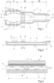
- the installation comprises a tank 1 provided with side walls 2 and end walls 3 and 4, respectively at the inlet and at the outlet of the tank 1.
- the tank 1 contains a bath of molten tin, or of any other suitable molten metal, referenced 7.
- the molten glass is poured onto the bath of molten metal 7 at its entrance, from a distribution channel 6 ending in a casting lip and arranged above the inlet wall 3 of the tank 1.
- the glass ribbon 8 which is formed on the bath of molten metal 7 is driven continuously at constant speed following a direction of longitudinal movement L from the entrance to the tank - that is to say the upstream side of the bath - until its exit - that is to say the downstream side of the bath - by extractor rollers 9 placed outside the tank 1 on the downstream side.
- the bath 7 defines several successive zones following the direction of longitudinal movement L of the glass ribbon 8. After being poured onto the bath of molten metal 7, the glass spreads freely as much as possible on the bath in a first zone I. A ribbon of glass 8 is thus formed which moves downstream under the effect of the traction of the extractor rollers 9.
- the glass ribbon in formation undergoes longitudinal forces directed outwards under the combined actions of extractor rollers 9 and knurled edge rollers 11.
- the knurled edge rollers 11 are generally made of steel and slightly oblique relative to the direction of longitudinal movement L of the glass ribbon 8. They are driven by motors 16 generally at different speeds depending on their position, and increasing downstream.
- the stretching of the glass begins and it becomes thinner.
- the glass ribbon takes its final shape under the action of the extractor rollers 9 driving it towards the exit from the bath.
- the second and third zones II, III together form the stretching zone which is followed by a fourth zone IV, called consolidation zone, where the frozen glass ribbon gradually cools.
- the critical zone corresponds to a viscosity between 10 4 Pa.s and 10 6 Pa.s, which corresponds, with regard to of a soda-lime glass, at a glass temperature of between 750°C and 900°C.
- the electromagnetic device 10 is designed to generate a magnetic field B with a vertical component in the critical zone Z of the molten metal bath 7.
- the electromagnetic device 10 is preferably arranged so that the field lines of the magnetic field B are contained in vertical planes parallel to the direction of movement L.
- the field B symbolized on the Figure 3 , is sliding in a direction G which corresponds to the direction of longitudinal movement L of the glass ribbon 8 so that the volume forces of Lorentz generated by the magnetic field stress the molten metal 7 in this same direction. It is preferable, however, for the intensity of the field B to be limited so that the volume forces of Lorentz do not drive the molten metal 7 under the glass ribbon 8 in the direction of movement L at a speed greater than that of the glass ribbon 8.
- the field B is preferably applied continuously in the critical zone Z of the bath while the glass ribbon 8 is driven continuously on the bath of molten metal 7 by the extractor rollers 9.
- the electromagnetic device 10 can be implemented in the form of a linear motor, for example a three-phase linear motor. Alternatively, it can be implemented by means of several linear motors placed side by side along the direction of longitudinal movement L and/or perpendicular to the latter so as to produce paving of the area of the bath to be subjected to the field B. In this case, the linear motors are synchronized so as to behave like a single linear motor, and therefore avoid in particular a break in the sliding of the magnetic field B.
- the electromagnetic device 10, particularly in the case where it is implemented by one or more linear motors, is preferably supported by a gantry. It is advantageous for this gantry to be movable relative to the bath of molten metal 7 in the direction of longitudinal movement L, which makes it possible to place the electromagnetic device at the level of the critical zone Z whose location in this direction can vary for example if we choose to produce glass of different thickness.
- the electromagnetic device 10 in particular if it is implemented by one or more linear motors, is preferentially maintained in a fixed position relative to the bath of molten metal 7, which avoids disturbing the application of the sliding field B relative to the bath of molten metal 7.
- the molten metal is subjected to the field B over the entire width of the glass ribbon 8 so that the molten metal 7 is subjected to the volume forces of Lorentz under the entire width of the glass ribbon 8.
- the field B is substantially homogeneous in the lateral direction - that is to say the direction perpendicular to the direction of longitudinal movement L -, in other words that the field B has the same intensity at all points of the molten metal at a given depth contained in the same section of the molten metal bath 7 perpendicular to the direction of movement L.
- the Lorentz volume forces exerted on the molten metal 7 are identical at all points at a given depth of a section of the molten metal bath.
- molten metal 7. help prevent the creation of turbulence in the flow of molten metal 7.
- the field B is not applied in the lateral direction over the entire width of the bath of molten metal 7, but that it stops at a lateral level which is intermediate between the glass ribbon 8 and the walls 2 of the tank 1.
- the electric current lines induced by the field B in the molten metal 7 - which lines are perpendicular to the direction of longitudinal movement L under the glass ribbon 8 - can loop back horizontally in the lateral region of the bath of molten metal 7 between the glass ribbon 8 and the walls 2 of the tank 1.
- This measure favorably limits the risk of generating harmful turbulence due to the Lorentz forces in the molten metal 7 at the level of the lateral zones of the glass ribbon 8, compared to the case where the current lines would loop back vertically in the lateral region of the molten metal bath 7 if the field B extended over the entire width of the molten metal bath 7, this that is to say up to the walls 2.
- the application of field B to the bath of molten metal 7 for all or part of the length of the critical zone Z provides an improvement in the optical quality of the glass obtained for a given driving speed of the glass ribbon 8 or, as a variant , makes it possible to increase to a certain extent the driving speed of the glass ribbon 8 without deteriorating the optical quality of the glass obtained.
- the field B is applied to the molten metal 7 over at least 15%, more preferably over at least 25%, more preferably still over at least 33%, or even at least 50%, and again more preferably over at least 75%, and even more advantageously over 100% of the length of the critical zone Z.
- the length portion of the critical zone Z to be covered depends on the optical quality to be obtained for the glass. Indeed, it was found that the impression of optical defects in the glass took place in sub-zones of more limited length inside the critical zone Z which are different depending on the size of the optical defects considered. The location of the sub-zones as a function of the size of the optical defects can be determined by numerical simulation or experimentally, for example by comparing the optical quality of the glass obtained with and without application of a field B as described over a limited length of the critical zone Z.
- the bottom or sole 5 of the tank 1 is flat at least in the entire critical zone Z - or more preferably also for the entire upstream part of the tank 1 in order to avoid creating turbulence in the molten metal 7 in the critical zone Z that would otherwise be created by the obstacles in tank 1.
- the field B is defined so that, under the glass ribbon 8 in the zone of application of the field B, the molten metal 7 is driven in the direction of longitudinal movement L at the same speed as the glass ribbon 8.
- the shearing of the molten metal 7 is almost non-existent at the interface of the molten metal 7 with the glass ribbon 8 since they move at the same speed.
- the turbulence in the molten metal at this interface is significantly eliminated and therefore also the correlative defects which were therefore imprinted on the surface of the glass.
- the molten metal 7 is thus carried under the glass ribbon 8 over the entire depth of the bath so as to leave only a layer of molten metal 7 of limited thickness - called Hartmann layer - at the interface with the sole 5 of the tank which flows in a laminar manner.
- FIG 4 schematically illustrates this situation with V representing the speed of movement of the glass ribbon 8 in the direction L and v m representing the speed of movement of the molten metal 7 in the direction L as a function of the depth of the bath.
- the speed V B of sliding of the field B in the direction of longitudinal movement L is chosen equal to the speed V of driving the glass ribbon 8 in this same direction and the effective value of the field B is chosen sufficiently high so that the Lorentz volume forces are sufficient to provide the aforementioned driving effect of the molten metal 7.
- the Lorentz forces it is advantageous for the Lorentz forces to be sufficient to drive the glass ribbon 8 at the driving speed in direction L by at least 5%, more preferably still at least 15%, more preferably at least 25%, more preferably still at least 33%, even more preferably at least 50%, even more preferably at least 66%, or even more preferably still at least 75% of the total thickness of molten metal 7 immediately under the glass ribbon 8 in the zone of application of field B.
- this volume force characterizes a magnetohydrodynamic interaction since it is linked to the speed of movement of the metal.
- this first mode of operation can be called 'magnetohydrodynamic' mode of operation or 'MHD' mode of operation.
- the interaction parameter N makes it possible to relate the effects of the Lorentz forces on the molten metal 7 to those of the inertia of the molten metal 7. If ideally the interaction parameter N can be chosen equal to 1, the numerical simulations have shown that it is possible to set it satisfactorily at a lower value. However, it is preferable that it be chosen greater than or equal to 0.1, more preferably greater than or equal to 0.33, even more preferably greater than or equal to 0.5, and more preferably greater than 0.75.
- the sliding speed of the field B in the direction L is chosen to be significantly higher than the driving speed of the glass ribbon 8 in this same direction, namely preferably at least 5 times higher, more preferably at least 10 times higher, more preferably at least 50 times higher and more preferably still at least 100 times higher.
- This other implementation is interesting in the case where the implementation of the electromagnetic device 10 is delicate to reach the desirable frequency of the field B in the implementation described above.
- the Lorentz volume forces acting on the molten metal 7 is sufficient so that, for a part of the thickness of molten metal 7 located immediately under the glass ribbon 8, the speed of movement of the molten metal 7 in the direction L is substantially equal to the driving speed of the glass ribbon in the direction L.
- the Figure 5 schematically illustrates this situation with V representing the speed of movement of the glass ribbon 8 in the direction L and v M representing the speed of movement of the molten metal 7 in the direction L as a function of the depth of the bath.
- the speed V B of the field B and the effective value of its intensity B e are chosen so as to obtain a Lorentz volume force sufficient to compensate for the friction stress exerted at the interface between the molten metal 7 and the hearth.
- the Lorentz volume force F B is preferably chosen substantially equal to ⁇ w / h , with ' ⁇ w ' the friction stress exerted by the hearth 5 on the molten metal 7 and ⁇ h' the depth of the molten metal bath 7 in the area of application of field B.
- the frequency of the field B be fixed at a sufficiently high value so that the pulsations of the Lorentz forces are too fast to create turbulence in the bath of molten metal 7 capable of being printed on the surface of the glass ribbon 8.
- the frequency of the field B is chosen less than or equal to: f ⁇ 1 ⁇ ⁇ 0 ⁇ h 2 with h: the depth in meters of the molten metal bath 7 in the area of application of field B.
- the value of the frequency of field B is preferably chosen so that the thickness of the magnetic skin is less than the depth of the bath of molten metal 7 in the zone of application of field B.
- the frequency of field B is fixed so that the thickness of the magnetic skin is at least equal to 15% of the depth of the molten metal bath 7 in the zone of application of field B, or even at least equal to 25% of it, or even at least equal to 33% of it, or even at least 50% of it, or even at least equal to 75% of it.
- the thickness of the magnetic skin by using, for example, a frequency of magnetic field B of 50 Hz, which corresponds to an intensity of 3.10 -4 T, which corresponds to a magnetic skin thickness of 2.4 cm, or more than 37% of the thickness of the molten metal from the interface with the glass.
- the intensity of the field B could be significantly lower than in the previous implementation for which the sliding speed V B is equal to the driving speed V of the glass ribbon 8.
- the electromagnetic device 10 is preferably arranged above the bath of molten metal 7, but could also be placed under the tank 1. Furthermore, it is preferable that the electromagnetic device 10 is thermally isolated from the bath and cooled, for example by water, in order to avoid overheating. It is advantageous for the electromagnetic device 10 to adjust the frequency of the field B so as to adjust the sliding speed V B of the field B as needed. Similarly, it is advantageous for the electromagnetic device 10 to adjust the intensity B e of the field B as needed, for example by means of a voltage variator.
Landscapes
- Chemical & Material Sciences (AREA)
- Engineering & Computer Science (AREA)
- Organic Chemistry (AREA)
- Materials Engineering (AREA)
- Chemical Kinetics & Catalysis (AREA)
- Health & Medical Sciences (AREA)
- Manufacturing & Machinery (AREA)
- Medicinal Chemistry (AREA)
- Polymers & Plastics (AREA)
- Continuous Casting (AREA)
- Glass Compositions (AREA)
- Surface Treatment Of Glass (AREA)
- Coating With Molten Metal (AREA)
- Surface Treatment Of Glass Fibres Or Filaments (AREA)
Claims (18)
- Verfahren zum Herstellen von Flachglas durch Flotation eines Glasbands (8) auf einem Bad aus geschmolzenem Metall (7), vorzugsweise aus geschmolzenem Zinn, wobei das Glasband (8) entlang einer Längsbewegungsrichtung (L) von einer stromaufwärtigen Seite des Bads (3), wo das geschmolzene Glas kontinuierlich auf das geschmolzene Metall (7) gegossen wird, bis zu einer stromabwärtigen Seite des Bads (4), wo das erstarrte Glasband das Bad verlässt, mitgeführt wird, das Verfahren umfassend:- Aussetzen des geschmolzenen Metalls (7) gegenüber einem Magnetfeld (B) mit einer vertikalen Komponente und gleitend in die Längsbewegungsrichtung (F) des Glasbands (8), wobei das Magnetfeld (B) ganz oder teilweise auf das geschmolzene Metall (7) angelegt wird, das sich unter dem Glasband (8) in einem Bereich (Z) des Bads befindet, für den das Glas die folgende Beziehung erfüllt:
 - h: die Dicke des Glasbands ist.
 - Verfahren nach Anspruch 1, wobei das Magnetfeld (B) gewählt wird, sodass Turbulenzen in dem geschmolzenen Metall an der Grenzfläche zu dem Glasband in dem Anwendungsbereich des Magnetfelds (B) verringert oder beseitigt werden.
- Verfahren nach Anspruch 1 oder 2, wobei das Magnetfeld (B) gewählt wird, sodass für mindestens einen Teil der Dicke des geschmolzenen Metalls, das sich unmittelbar unter dem Glasband in dem Anwendungsbereich des Magnetfelds (B) befindet, das geschmolzene Metall in der Längsbewegungsrichtung (F) des Glasbands (8) mit der gleichen Geschwindigkeit wie das Glasband (8) mitgeführt wird.
- Verfahren nach Anspruch 3, wobei der Teil der Dicke des geschmolzenen Metalls (7), der sich unmittelbar unter dem Glasband in dem Anwendungsbereich des Magnetfelds (B) befindet, mindestens 5 %, mehr bevorzugt mindestens 15 %, noch mehr bevorzugt mindestens 25 %, noch mehr bevorzugt mindestens 33 %, noch mehr bevorzugt mindestens 50 %, noch mehr bevorzugt mindestens 66 %, sogar noch mehr bevorzugt mindestens 75 % der Gesamtdicke des geschmolzenen Metalls (7) unter dem Glasband (8) in dem Anwendungsbereich des Felds (B) entspricht.
- Verfahren nach einem der Ansprüche 1 bis 4, umfassend:- Aussetzen des geschmolzenen Metalls (7) gegenüber dem Magnetfeld (B) über mindestens 15 %, mehr bevorzugt über mindestens 25 %, noch mehr bevorzugt über mindestens 33 %, noch mehr bevorzugt über mindestens 50 %, noch mehr bevorzugt über mindestens 75 % und noch vorteilhafter über 100 % der Länge des Bereichs (Z) des Bads, gemessen in der Längsbewegungsrichtung (L) des Glasbands (8).
- Verfahren nach einem der Ansprüche 1 bis 5, umfassend:- Aussetzen des geschmolzenen Metalls (7) gegenüber dem Magnetfeld (B) über die gesamte Breite des Glasbands (8).
- Verfahren nach Anspruch 6, umfassend:- Aussetzen des geschmolzenen Metalls (7) gegenüber dem Magnetfeld (B) über mindestens die gesamte Breite des Glasbands (8), ohne dort das geschmolzene Metall (7) in einer Region, die an den Seitenrand des Bads auf jeder Seite des Glasbands (8) angrenzt, auszusetzen.
- Verfahren nach einem der Ansprüche 1 bis 7, umfassend:- Gleiten lassen des Magnetfelds (B) in der Längsbewegungsrichtung (L) mit einer Gleitgeschwindigkeit (VB), die im Wesentlichen gleich der Längsbewegungsgeschwindigkeit (V) des Glasbands (8) ist.
- Verfahren nach Anspruch 8, ferner umfassend:- Wählen der Intensität (Be) des Magnetfelds (B), um das geschmolzene Metall (7) in der Längsbewegungsrichtung (L) mit der Längsbewegungsgeschwindigkeit (V) des Glasbands (8) zu mindestens 5 %, noch mehr bevorzugt zu mindestens 15 %, noch mehr bevorzugt zu mindestens 25 %, noch mehr bevorzugt zu mindestens 33 %, noch mehr bevorzugt zu mindestens 50 %, noch mehr bevorzugt zu mindestens 66 % und noch mehr bevorzugt zu mindestens 75 % der Dicke des geschmolzenen Metalls (7), das sich unmittelbar unter dem Glasband (8) in dem Anwendungsbereich des Magnetfelds (B) befindet, mitzuführen.
- Verfahren nach Anspruch 8 oder 9, ferner umfassend:- Beschleunigen der Abkühlung des Glasbands (8) in dem Anwendungsbereich des Magnetfelds (B).
- Verfahren nach einem der Ansprüche 1 bis 7, umfassend:- Gleiten lassen des Magnetfelds in der Längsbewegungsrichtung (L) mit einer Gleitgeschwindigkeit (VB), die im Wesentlichen größer als die Längsbewegungsgeschwindigkeit (V) des Glasbands (8) ist.
- Verfahren nach Anspruch 11, wobei die Gleitgeschwindigkeit (VB) des Magnetfelds (B) gewählt ist, um mindestens 5-mal größer, mehr bevorzugt mindestens 10-mal größer, mehr bevorzugt mindestens 50-mal größer und noch mehr bevorzugt mindestens 100-mal größer als die Längsbewegungsgeschwindigkeit (V) des Glasbands (8) zu sein.
- Verfahren nach Anspruch 11 oder 12, umfassend:- Wählen der Gleitgeschwindigkeit (VB) des Magnetfelds (B) in der Längsbewegungsrichtung (L) und der Intensität (Be) des Magnetfelds (B), damit, in dem Anwendungsbereich des Magnetfelds (B), das geschmolzene Metall (7) in der Längsbewegungsrichtung (L) im Wesentlichen mit der Längsbewegungsgeschwindigkeit (V) des Glasbands (8) über mindestens 5 % der Dicke des geschmolzenen Metalls (7), das sich unmittelbar unter dem Glasband (8) befindet, bewegt wird.
- Verfahren nach einem der Ansprüche 11 bis 13, umfassend:- Wählen der Gleitgeschwindigkeit (VB) des Magnetfelds (B) in der Längsbewegungsrichtung (L) und der Intensität (Be) des Magnetfelds (B), damit, in dem Anwendungsbereich des Magnetfelds (B), das geschmolzene Metall (7) in der Längsbewegungsrichtung (L) mit einer Geschwindigkeit, die kleiner als oder gleich der Längsbewegungsgeschwindigkeit (V) des Glasbands (8) ist, über die gesamte Tiefe des Bads aus geschmolzenem Metall (7) bewegt wird.
- Verfahren nach einem der Ansprüche 11 bis 14, wobei die Frequenz des Magnetfelds (B) festgelegt wird, sodass die Dicke der magnetischen Haut mindestens gleich bis mindestens 5 %, mehr bevorzugt bis mindestens 15 %, noch mehr bevorzugt bis mindestens 25 %, noch mehr bevorzugt bis mindestens 33 %, noch mehr bevorzugt bis mindestens 50 % und noch vorteilhafter bis 75 % der Tiefe des Bads aus geschmolzenem Metall (7) in dem Anwendungsbereich des Magnetfelds (B) beträgt.
- Verfahren nach einem der Ansprüche 1 bis 15, umfassend das Erzeugen des Magnetfelds (B) mittels einer elektromagnetischen Vorrichtung (10).
- Verfahren nach Anspruch 16, wobei die elektromagnetische Vorrichtung (10) in einer festen Position relativ zu dem Bad aus geschmolzenem Metall (7), während des Schritts des Aussetzens des geschmolzenen Metalls gegenüber dem Magnetfeld (B), gehalten wird.
- Verfahren nach Anspruch 16 oder 17, wobei die elektromagnetische Vorrichtung (10) über dem Bad aus geschmolzenem Metall (7), während des Schritts des Aussetzens des geschmolzenen Metalls gegenüber dem Magnetfeld (B), angeordnet ist.
Applications Claiming Priority (2)
| Application Number | Priority Date | Filing Date | Title |
|---|---|---|---|
| FR1663357A FR3061171B1 (fr) | 2016-12-23 | 2016-12-23 | Procede ameliore de fabrication de verre plat par flottage |
| PCT/FR2017/053843 WO2018115801A1 (fr) | 2016-12-23 | 2017-12-24 | Procédé amélioré de fabrication de verre plat par flottage |
Publications (2)
| Publication Number | Publication Date |
|---|---|
| EP3558880A1 EP3558880A1 (de) | 2019-10-30 |
| EP3558880B1 true EP3558880B1 (de) | 2024-08-07 |
Family
ID=58455214
Family Applications (1)
| Application Number | Title | Priority Date | Filing Date |
|---|---|---|---|
| EP17838055.6A Active EP3558880B1 (de) | 2016-12-23 | 2017-12-24 | Verbessertes verfahren zur herstellung von flachglas durch floating |
Country Status (7)
| Country | Link |
|---|---|
| EP (1) | EP3558880B1 (de) |
| KR (1) | KR102417566B1 (de) |
| CN (1) | CN110072820B (de) |
| CO (1) | CO2019006505A2 (de) |
| FR (1) | FR3061171B1 (de) |
| MX (1) | MX2019007438A (de) |
| WO (1) | WO2018115801A1 (de) |
Families Citing this family (2)
| Publication number | Priority date | Publication date | Assignee | Title |
|---|---|---|---|---|
| KR102798763B1 (ko) | 2019-08-09 | 2025-04-22 | 주식회사 엘지에너지솔루션 | 제조 설비 품질에 대한 정량화 진단법 |
| CN111646679A (zh) * | 2020-06-17 | 2020-09-11 | 洛玻集团洛阳龙海电子玻璃有限公司 | 超薄浮法玻璃生产中直线电机的使用方法 |
Family Cites Families (6)
| Publication number | Priority date | Publication date | Assignee | Title |
|---|---|---|---|---|
| JPH07108779B2 (ja) * | 1987-08-24 | 1995-11-22 | 旭硝子株式会社 | フロ−トガラスの製造法 |
| JP2005289795A (ja) * | 2004-03-11 | 2005-10-20 | Asahi Glass Co Ltd | フロート板ガラス製造方法及びその装置 |
| JP4725153B2 (ja) * | 2004-04-06 | 2011-07-13 | 旭硝子株式会社 | フロート板ガラス製造方法及びその装置 |
| DE102007014806A1 (de) * | 2007-03-28 | 2008-10-02 | Schott Ag | Verfahren und Vorrichtung zur Bewegung einer freien Metalloberfläche geschmolzenen Metalls |
| KR101563682B1 (ko) * | 2009-02-13 | 2015-10-28 | 주식회사 엘지화학 | 유리판 제조 장치 |
| KR101561973B1 (ko) * | 2009-02-13 | 2015-10-21 | 주식회사 엘지화학 | 유리판 제조 장치 |
-
2016
- 2016-12-23 FR FR1663357A patent/FR3061171B1/fr active Active
-
2017
- 2017-12-24 EP EP17838055.6A patent/EP3558880B1/de active Active
- 2017-12-24 CN CN201780079625.3A patent/CN110072820B/zh active Active
- 2017-12-24 KR KR1020197017750A patent/KR102417566B1/ko active Active
- 2017-12-24 WO PCT/FR2017/053843 patent/WO2018115801A1/fr not_active Ceased
- 2017-12-24 MX MX2019007438A patent/MX2019007438A/es unknown
-
2019
- 2019-06-20 CO CONC2019/0006505A patent/CO2019006505A2/es unknown
Also Published As
| Publication number | Publication date |
|---|---|
| KR20190097050A (ko) | 2019-08-20 |
| FR3061171A1 (fr) | 2018-06-29 |
| WO2018115801A1 (fr) | 2018-06-28 |
| FR3061171B1 (fr) | 2020-11-13 |
| CN110072820A (zh) | 2019-07-30 |
| MX2019007438A (es) | 2019-08-16 |
| WO2018115801A9 (fr) | 2019-10-10 |
| BR112019011791A2 (pt) | 2019-10-29 |
| CO2019006505A2 (es) | 2019-07-31 |
| CN110072820B (zh) | 2022-06-24 |
| EP3558880A1 (de) | 2019-10-30 |
| KR102417566B1 (ko) | 2022-07-07 |
Similar Documents
| Publication | Publication Date | Title |
|---|---|---|
| EP1349817B1 (de) | Verfahrem zum schneiden der ränder eines glasbandes sowie vorrichtung zur durchführung des verfahrens | |
| EP3558880B1 (de) | Verbessertes verfahren zur herstellung von flachglas durch floating | |
| EP1177155B1 (de) | Verfahren zur herstellung von floatglass, vorrichtung zur herstellung und hergestelltes produkt | |
| CA2650187A1 (fr) | Perfectionnement apporte aux sections de chauffage rapide des lignes de traitement thermique en continu | |
| EP3621928B1 (de) | Verbessertes verfahren und anlage zur herstellung von flachglas durch einen flotationsglasprozess | |
| EP0830318B1 (de) | Verfahren zum herstellen von floatglasscheiben | |
| EP2501658A1 (de) | Verfahren für den kontinuierlichen druck von präzisionsstrukturen auf ein glasband und auf diese weise gewonnenes glasband | |
| FR3014449A1 (fr) | Appareil et procede de chauffage par induction pour section de recuit apres galvanisation. | |
| CA3011266C (fr) | Dispositif pour la stabilisation hydrodynamique d'une bande metallique en defilement continu | |
| WO1996002684A1 (fr) | Procede de dimensionnement d'une enceinte de galvanisation pourvue d'un dispositif d'essuyage magnetique de produits metallurgiques galvanises | |
| FR2492804A1 (fr) | Procede de production d'une feuille mince de verre par processus de flottage | |
| EP2739578B1 (de) | Floatkammer zur herstellung von glas | |
| EP3746411A1 (de) | Herstellung von glas mit keilförmigem querschnitt in einer floatglasherstellungsanlage | |
| WO2009071764A1 (fr) | Culasse feuilletée refendue en peigne pour inducteur à champ magnétique traversant de réchauffage de bandes métalliques | |
| EP2396285B1 (de) | Herstellung von texturiertem flachglas durch floating | |
| BE826838A (fr) | Appareil pour la coulee continue de metaux | |
| BR112019011791B1 (pt) | Método para fabricar vidro plano por flutuação | |
| EP2566996A1 (de) | Karbonband zur aufnahme einer halbleitermaterialschicht | |
| BE401533A (de) | ||
| BE410586A (de) | ||
| BE546165A (de) |
Legal Events
| Date | Code | Title | Description |
|---|---|---|---|
| STAA | Information on the status of an ep patent application or granted ep patent |
Free format text: STATUS: UNKNOWN |
|
| STAA | Information on the status of an ep patent application or granted ep patent |
Free format text: STATUS: THE INTERNATIONAL PUBLICATION HAS BEEN MADE |
|
| PUAI | Public reference made under article 153(3) epc to a published international application that has entered the european phase |
Free format text: ORIGINAL CODE: 0009012 |
|
| STAA | Information on the status of an ep patent application or granted ep patent |
Free format text: STATUS: REQUEST FOR EXAMINATION WAS MADE |
|
| 17P | Request for examination filed |
Effective date: 20190723 |
|
| AK | Designated contracting states |
Kind code of ref document: A1 Designated state(s): AL AT BE BG CH CY CZ DE DK EE ES FI FR GB GR HR HU IE IS IT LI LT LU LV MC MK MT NL NO PL PT RO RS SE SI SK SM TR |
|
| AX | Request for extension of the european patent |
Extension state: BA ME |
|
| DAV | Request for validation of the european patent (deleted) | ||
| DAX | Request for extension of the european patent (deleted) | ||
| RAP1 | Party data changed (applicant data changed or rights of an application transferred) |
Owner name: SAINT-GOBAIN GLASS FRANCE |
|
| STAA | Information on the status of an ep patent application or granted ep patent |
Free format text: STATUS: EXAMINATION IS IN PROGRESS |
|
| 17Q | First examination report despatched |
Effective date: 20230609 |
|
| GRAP | Despatch of communication of intention to grant a patent |
Free format text: ORIGINAL CODE: EPIDOSNIGR1 |
|
| STAA | Information on the status of an ep patent application or granted ep patent |
Free format text: STATUS: GRANT OF PATENT IS INTENDED |
|
| INTG | Intention to grant announced |
Effective date: 20240412 |
|
| GRAS | Grant fee paid |
Free format text: ORIGINAL CODE: EPIDOSNIGR3 |
|
| GRAA | (expected) grant |
Free format text: ORIGINAL CODE: 0009210 |
|
| STAA | Information on the status of an ep patent application or granted ep patent |
Free format text: STATUS: THE PATENT HAS BEEN GRANTED |
|
| AK | Designated contracting states |
Kind code of ref document: B1 Designated state(s): AL AT BE BG CH CY CZ DE DK EE ES FI FR GB GR HR HU IE IS IT LI LT LU LV MC MK MT NL NO PL PT RO RS SE SI SK SM TR |
|
| REG | Reference to a national code |
Ref country code: GB Ref legal event code: FG4D Free format text: NOT ENGLISH |
|
| REG | Reference to a national code |
Ref country code: CH Ref legal event code: EP |
|
| REG | Reference to a national code |
Ref country code: IE Ref legal event code: FG4D Free format text: LANGUAGE OF EP DOCUMENT: FRENCH |
|
| REG | Reference to a national code |
Ref country code: DE Ref legal event code: R096 Ref document number: 602017083942 Country of ref document: DE |
|
| P01 | Opt-out of the competence of the unified patent court (upc) registered |
Free format text: CASE NUMBER: APP_53688/2024 Effective date: 20240926 |
|
| REG | Reference to a national code |
Ref country code: LT Ref legal event code: MG9D |
|
| REG | Reference to a national code |
Ref country code: NL Ref legal event code: MP Effective date: 20240807 |
|
| PGFP | Annual fee paid to national office [announced via postgrant information from national office to epo] |
Ref country code: DE Payment date: 20241029 Year of fee payment: 8 |
|
| PG25 | Lapsed in a contracting state [announced via postgrant information from national office to epo] |
Ref country code: NO Free format text: LAPSE BECAUSE OF FAILURE TO SUBMIT A TRANSLATION OF THE DESCRIPTION OR TO PAY THE FEE WITHIN THE PRESCRIBED TIME-LIMIT Effective date: 20241107 |
|
| REG | Reference to a national code |
Ref country code: AT Ref legal event code: MK05 Ref document number: 1710777 Country of ref document: AT Kind code of ref document: T Effective date: 20240807 |
|
| PG25 | Lapsed in a contracting state [announced via postgrant information from national office to epo] |
Ref country code: PT Free format text: LAPSE BECAUSE OF FAILURE TO SUBMIT A TRANSLATION OF THE DESCRIPTION OR TO PAY THE FEE WITHIN THE PRESCRIBED TIME-LIMIT Effective date: 20241209 Ref country code: FI Free format text: LAPSE BECAUSE OF FAILURE TO SUBMIT A TRANSLATION OF THE DESCRIPTION OR TO PAY THE FEE WITHIN THE PRESCRIBED TIME-LIMIT Effective date: 20240807 Ref country code: NL Free format text: LAPSE BECAUSE OF FAILURE TO SUBMIT A TRANSLATION OF THE DESCRIPTION OR TO PAY THE FEE WITHIN THE PRESCRIBED TIME-LIMIT Effective date: 20240807 Ref country code: GR Free format text: LAPSE BECAUSE OF FAILURE TO SUBMIT A TRANSLATION OF THE DESCRIPTION OR TO PAY THE FEE WITHIN THE PRESCRIBED TIME-LIMIT Effective date: 20241108 Ref country code: PL Free format text: LAPSE BECAUSE OF FAILURE TO SUBMIT A TRANSLATION OF THE DESCRIPTION OR TO PAY THE FEE WITHIN THE PRESCRIBED TIME-LIMIT Effective date: 20240807 |
|
| PG25 | Lapsed in a contracting state [announced via postgrant information from national office to epo] |
Ref country code: BG Free format text: LAPSE BECAUSE OF FAILURE TO SUBMIT A TRANSLATION OF THE DESCRIPTION OR TO PAY THE FEE WITHIN THE PRESCRIBED TIME-LIMIT Effective date: 20240807 |
|
| PG25 | Lapsed in a contracting state [announced via postgrant information from national office to epo] |
Ref country code: LV Free format text: LAPSE BECAUSE OF FAILURE TO SUBMIT A TRANSLATION OF THE DESCRIPTION OR TO PAY THE FEE WITHIN THE PRESCRIBED TIME-LIMIT Effective date: 20240807 |
|
| PG25 | Lapsed in a contracting state [announced via postgrant information from national office to epo] |
Ref country code: AT Free format text: LAPSE BECAUSE OF FAILURE TO SUBMIT A TRANSLATION OF THE DESCRIPTION OR TO PAY THE FEE WITHIN THE PRESCRIBED TIME-LIMIT Effective date: 20240807 Ref country code: IS Free format text: LAPSE BECAUSE OF FAILURE TO SUBMIT A TRANSLATION OF THE DESCRIPTION OR TO PAY THE FEE WITHIN THE PRESCRIBED TIME-LIMIT Effective date: 20241207 |
|
| PG25 | Lapsed in a contracting state [announced via postgrant information from national office to epo] |
Ref country code: HR Free format text: LAPSE BECAUSE OF FAILURE TO SUBMIT A TRANSLATION OF THE DESCRIPTION OR TO PAY THE FEE WITHIN THE PRESCRIBED TIME-LIMIT Effective date: 20240807 |
|
| PG25 | Lapsed in a contracting state [announced via postgrant information from national office to epo] |
Ref country code: RS Free format text: LAPSE BECAUSE OF FAILURE TO SUBMIT A TRANSLATION OF THE DESCRIPTION OR TO PAY THE FEE WITHIN THE PRESCRIBED TIME-LIMIT Effective date: 20241107 Ref country code: ES Free format text: LAPSE BECAUSE OF FAILURE TO SUBMIT A TRANSLATION OF THE DESCRIPTION OR TO PAY THE FEE WITHIN THE PRESCRIBED TIME-LIMIT Effective date: 20240807 |
|
| PG25 | Lapsed in a contracting state [announced via postgrant information from national office to epo] |
Ref country code: RS Free format text: LAPSE BECAUSE OF FAILURE TO SUBMIT A TRANSLATION OF THE DESCRIPTION OR TO PAY THE FEE WITHIN THE PRESCRIBED TIME-LIMIT Effective date: 20241107 Ref country code: PT Free format text: LAPSE BECAUSE OF FAILURE TO SUBMIT A TRANSLATION OF THE DESCRIPTION OR TO PAY THE FEE WITHIN THE PRESCRIBED TIME-LIMIT Effective date: 20241209 Ref country code: PL Free format text: LAPSE BECAUSE OF FAILURE TO SUBMIT A TRANSLATION OF THE DESCRIPTION OR TO PAY THE FEE WITHIN THE PRESCRIBED TIME-LIMIT Effective date: 20240807 Ref country code: NO Free format text: LAPSE BECAUSE OF FAILURE TO SUBMIT A TRANSLATION OF THE DESCRIPTION OR TO PAY THE FEE WITHIN THE PRESCRIBED TIME-LIMIT Effective date: 20241107 Ref country code: NL Free format text: LAPSE BECAUSE OF FAILURE TO SUBMIT A TRANSLATION OF THE DESCRIPTION OR TO PAY THE FEE WITHIN THE PRESCRIBED TIME-LIMIT Effective date: 20240807 Ref country code: LV Free format text: LAPSE BECAUSE OF FAILURE TO SUBMIT A TRANSLATION OF THE DESCRIPTION OR TO PAY THE FEE WITHIN THE PRESCRIBED TIME-LIMIT Effective date: 20240807 Ref country code: IS Free format text: LAPSE BECAUSE OF FAILURE TO SUBMIT A TRANSLATION OF THE DESCRIPTION OR TO PAY THE FEE WITHIN THE PRESCRIBED TIME-LIMIT Effective date: 20241207 Ref country code: HR Free format text: LAPSE BECAUSE OF FAILURE TO SUBMIT A TRANSLATION OF THE DESCRIPTION OR TO PAY THE FEE WITHIN THE PRESCRIBED TIME-LIMIT Effective date: 20240807 Ref country code: GR Free format text: LAPSE BECAUSE OF FAILURE TO SUBMIT A TRANSLATION OF THE DESCRIPTION OR TO PAY THE FEE WITHIN THE PRESCRIBED TIME-LIMIT Effective date: 20241108 Ref country code: FI Free format text: LAPSE BECAUSE OF FAILURE TO SUBMIT A TRANSLATION OF THE DESCRIPTION OR TO PAY THE FEE WITHIN THE PRESCRIBED TIME-LIMIT Effective date: 20240807 Ref country code: ES Free format text: LAPSE BECAUSE OF FAILURE TO SUBMIT A TRANSLATION OF THE DESCRIPTION OR TO PAY THE FEE WITHIN THE PRESCRIBED TIME-LIMIT Effective date: 20240807 Ref country code: BG Free format text: LAPSE BECAUSE OF FAILURE TO SUBMIT A TRANSLATION OF THE DESCRIPTION OR TO PAY THE FEE WITHIN THE PRESCRIBED TIME-LIMIT Effective date: 20240807 Ref country code: AT Free format text: LAPSE BECAUSE OF FAILURE TO SUBMIT A TRANSLATION OF THE DESCRIPTION OR TO PAY THE FEE WITHIN THE PRESCRIBED TIME-LIMIT Effective date: 20240807 |
|
| PG25 | Lapsed in a contracting state [announced via postgrant information from national office to epo] |
Ref country code: SM Free format text: LAPSE BECAUSE OF FAILURE TO SUBMIT A TRANSLATION OF THE DESCRIPTION OR TO PAY THE FEE WITHIN THE PRESCRIBED TIME-LIMIT Effective date: 20240807 Ref country code: DK Free format text: LAPSE BECAUSE OF FAILURE TO SUBMIT A TRANSLATION OF THE DESCRIPTION OR TO PAY THE FEE WITHIN THE PRESCRIBED TIME-LIMIT Effective date: 20240807 Ref country code: RO Free format text: LAPSE BECAUSE OF FAILURE TO SUBMIT A TRANSLATION OF THE DESCRIPTION OR TO PAY THE FEE WITHIN THE PRESCRIBED TIME-LIMIT Effective date: 20240807 |
|
| PG25 | Lapsed in a contracting state [announced via postgrant information from national office to epo] |
Ref country code: EE Free format text: LAPSE BECAUSE OF FAILURE TO SUBMIT A TRANSLATION OF THE DESCRIPTION OR TO PAY THE FEE WITHIN THE PRESCRIBED TIME-LIMIT Effective date: 20240807 |
|
| PG25 | Lapsed in a contracting state [announced via postgrant information from national office to epo] |
Ref country code: CZ Free format text: LAPSE BECAUSE OF FAILURE TO SUBMIT A TRANSLATION OF THE DESCRIPTION OR TO PAY THE FEE WITHIN THE PRESCRIBED TIME-LIMIT Effective date: 20240807 |
|
| PG25 | Lapsed in a contracting state [announced via postgrant information from national office to epo] |
Ref country code: SK Free format text: LAPSE BECAUSE OF FAILURE TO SUBMIT A TRANSLATION OF THE DESCRIPTION OR TO PAY THE FEE WITHIN THE PRESCRIBED TIME-LIMIT Effective date: 20240807 |
|
| REG | Reference to a national code |
Ref country code: DE Ref legal event code: R097 Ref document number: 602017083942 Country of ref document: DE |
|
| PLBE | No opposition filed within time limit |
Free format text: ORIGINAL CODE: 0009261 |
|
| STAA | Information on the status of an ep patent application or granted ep patent |
Free format text: STATUS: NO OPPOSITION FILED WITHIN TIME LIMIT |
|
| PG25 | Lapsed in a contracting state [announced via postgrant information from national office to epo] |
Ref country code: MC Free format text: LAPSE BECAUSE OF FAILURE TO SUBMIT A TRANSLATION OF THE DESCRIPTION OR TO PAY THE FEE WITHIN THE PRESCRIBED TIME-LIMIT Effective date: 20240807 |
|
| 26N | No opposition filed |
Effective date: 20250508 |
|
| REG | Reference to a national code |
Ref country code: CH Ref legal event code: PL |
|
| PG25 | Lapsed in a contracting state [announced via postgrant information from national office to epo] |
Ref country code: LU Free format text: LAPSE BECAUSE OF NON-PAYMENT OF DUE FEES Effective date: 20241224 |
|
| GBPC | Gb: european patent ceased through non-payment of renewal fee |
Effective date: 20241224 |
|
| PG25 | Lapsed in a contracting state [announced via postgrant information from national office to epo] |
Ref country code: SE Free format text: LAPSE BECAUSE OF FAILURE TO SUBMIT A TRANSLATION OF THE DESCRIPTION OR TO PAY THE FEE WITHIN THE PRESCRIBED TIME-LIMIT Effective date: 20240807 |
|
| REG | Reference to a national code |
Ref country code: BE Ref legal event code: MM Effective date: 20241231 |
|
| PG25 | Lapsed in a contracting state [announced via postgrant information from national office to epo] |
Ref country code: GB Free format text: LAPSE BECAUSE OF NON-PAYMENT OF DUE FEES Effective date: 20241224 Ref country code: BE Free format text: LAPSE BECAUSE OF NON-PAYMENT OF DUE FEES Effective date: 20241231 |
|
| PG25 | Lapsed in a contracting state [announced via postgrant information from national office to epo] |
Ref country code: FR Free format text: LAPSE BECAUSE OF NON-PAYMENT OF DUE FEES Effective date: 20241231 |
|
| PG25 | Lapsed in a contracting state [announced via postgrant information from national office to epo] |
Ref country code: CH Free format text: LAPSE BECAUSE OF NON-PAYMENT OF DUE FEES Effective date: 20241231 |
|
| PG25 | Lapsed in a contracting state [announced via postgrant information from national office to epo] |
Ref country code: IE Free format text: LAPSE BECAUSE OF NON-PAYMENT OF DUE FEES Effective date: 20241224 |