EP3558785B1 - Coupling arrangement, in particular for a rail vehicle - Google Patents
Coupling arrangement, in particular for a rail vehicle Download PDFInfo
- Publication number
- EP3558785B1 EP3558785B1 EP17786910.4A EP17786910A EP3558785B1 EP 3558785 B1 EP3558785 B1 EP 3558785B1 EP 17786910 A EP17786910 A EP 17786910A EP 3558785 B1 EP3558785 B1 EP 3558785B1
- Authority
- EP
- European Patent Office
- Prior art keywords
- coupling rod
- coupling
- bearing block
- bearing
- supporting structure
- Prior art date
- Legal status (The legal status is an assumption and is not a legal conclusion. Google has not performed a legal analysis and makes no representation as to the accuracy of the status listed.)
- Active
Links
- 230000008878 coupling Effects 0.000 title claims description 109
- 238000010168 coupling process Methods 0.000 title claims description 109
- 238000005859 coupling reaction Methods 0.000 title claims description 109
- 239000002184 metal Substances 0.000 claims description 2
- 230000003319 supportive effect Effects 0.000 claims 1
- 230000021715 photosynthesis, light harvesting Effects 0.000 description 5
- 230000002349 favourable effect Effects 0.000 description 4
- 238000005452 bending Methods 0.000 description 3
- NJPPVKZQTLUDBO-UHFFFAOYSA-N novaluron Chemical compound C1=C(Cl)C(OC(F)(F)C(OC(F)(F)F)F)=CC=C1NC(=O)NC(=O)C1=C(F)C=CC=C1F NJPPVKZQTLUDBO-UHFFFAOYSA-N 0.000 description 2
- 238000010008 shearing Methods 0.000 description 2
- 230000001419 dependent effect Effects 0.000 description 1
- 238000005265 energy consumption Methods 0.000 description 1
- 238000009434 installation Methods 0.000 description 1
- 239000000463 material Substances 0.000 description 1
- 238000000926 separation method Methods 0.000 description 1
- 239000000725 suspension Substances 0.000 description 1
- 230000007704 transition Effects 0.000 description 1
Images


Classifications
-
- B—PERFORMING OPERATIONS; TRANSPORTING
- B61—RAILWAYS
- B61G—COUPLINGS; DRAUGHT AND BUFFING APPLIANCES
- B61G9/00—Draw-gear
- B61G9/20—Details; Accessories
- B61G9/22—Supporting framework, e.g. cradles; Spring housings
-
- B—PERFORMING OPERATIONS; TRANSPORTING
- B61—RAILWAYS
- B61G—COUPLINGS; DRAUGHT AND BUFFING APPLIANCES
- B61G7/00—Details or accessories
- B61G7/10—Mounting of the couplings on the vehicle
Definitions
- the present invention relates to a clutch arrangement, in particular for a rail vehicle, according to the preamble of claim 1.
- FIG. 7 A previously known in practice generic clutch assembly is shown schematically in figure 7 shown.
- a coupling rod 1 which extends along a longitudinal axis 2 and carries a coupling head 3 in the region of a first axial end, is held in the bearing block 4 on the car body of a rail vehicle, not shown.
- a support structure 7 is provided, which supports the coupling rod 1 from below by means of a supporting spring 16 .
- the support spring 16 keeps the coupling rod 1 at the appropriate height because of its pretension, and because of its spring reserve it allows the necessary up and down movements.
- an opening for the bearing block 4 is provided in a base plate 9, which is attached to the car body.
- This opening is sufficiently large that the coupling rod 1 also fits through the opening in the event of an overload in the longitudinal direction, ie in the direction of the longitudinal axis 2 .
- Such an overload occurs when the rail vehicle collides with an obstacle and is also referred to as a crash.
- An energy dissipation element 8 is provided behind said opening, which deforms in the longitudinal direction when the overload occurs and thereby absorbs at least part of the excess force in the direction of the longitudinal axis 2 .
- the coupling rod 1 can at least partially slip through the opening of the base plate 9 and the connection to the support structure 7 or the support spring 16 is separated, for example by shearing.
- the support structure 7 occupies a comparatively large space below the coupling rod 1 and requires an additional bearing block 17 with which it is connected in an articulated manner to the base plate 9 and is carried by it.
- connection of the support is also an example in JP 2012-81934 A played back.
- EP 2862 777A1 and CN 105083318A disclose versions with the arrangement of the support below the coupling rod and connection.
- An embodiment of a support with the features from the preamble of claim 1 is from WO 2006/117045 A1 known.
- the carrier structure is designed as an element that completely encloses the coupling rod in the circumferential direction and over a partial area in the longitudinal direction.
- the present invention is based on the object of improving the generic clutch arrangement shown in such a way that the support structure takes up less space outside the clutch rod, advantageously has a lower weight and, in particular, changes the power flow as little as possible in the event of an overload and advantageously improves compatibility with the described energy consumption guaranteed.
- a coupling arrangement according to the invention which is particularly suitable for a rail vehicle but can also be used in other vehicles, the coupling arrangement being used, for example, to couple two rail vehicle parts to one another with corresponding coupling arrangements or coupling arrangements that work together, has a coupling rod which extends along a longitudinal axis and carries a coupling head in the region of a first axial end.
- a bearing block is provided, to which the coupling rod is connected in an articulated manner about a vertical axis with a second axial end arranged opposite to the first axial end.
- Connected in an articulated manner about a vertical axis means in particular that the connection creates a mechanically at least essentially rigid coupling in the direction of the longitudinal axis between the coupling rod and the bearing block, possibly apart from possible elastic deflections in particular, but at the same time a sufficiently large angular deflection of the coupling rod relative to the Bearing block and in particular an energy-absorbing element adjoining this and/or compared to a base plate enclosing the bearing block, so that the coupling rod can swing out to the side when cornering.
- a bearing is provided between the pedestal and the drawbar, configured to allow at least limited movement between the drawbar and the pedestal in the vertical direction. This can also be used to achieve height compensation. The movement is achieved, for example, by an elastic bearing. Additionally or alternatively, the bearing block is already movable in the vertical direction.
- a support structure which elastically supports the coupling rod against movement in the vertical direction in order to ensure the aforementioned holding of the coupling rod at the correct height.
- the support structure is positioned in the vertical direction at least predominantly at the level of the bearing block and/or the coupling rod, essentially coaxially with the longitudinal axis. This means that the majority of the support structure protrudes in the vertical direction only slightly beyond the coupling rod, for example by a maximum of half or a third of the way diameter of the coupling rod. It is also possible for the support structure to cling even more closely to the coupling rod, so that the support structure protrudes, for example, by only a quarter of the diameter or less beyond the coupling rod.
- the above statements relate at least to a side plan view in the horizontal direction of the coupling rod.
- the coupling rod is positioned at least substantially coaxially with the longitudinal axis, which means that the central axis or longitudinal axis of the support structure is arranged close to the longitudinal axis of the coupling rod, in particular runs within the outer circumference of the coupling rod, for example with a maximum distance of half a Radius of the tie rod or less, substantially no additional space outside the tie rod is blocked by the support structure.
- the support structure is therefore largely not arranged eccentrically to the coupling rod.
- the coupling arrangement is free of a support structure that is supported in an articulated manner in the radial direction of the coupling rod exclusively on one side outside of the coupling rod, whereby the term supported is to be understood as meaning any suspension of the corresponding component, here the support structure, in which the weight forces of the component and possibly on the Operating forces acting on the component are absorbed by the supporting element, for example by the bearing block or a base plate which is fastened, for example, to the car body.
- the support structure extends above and below the coupling rod and/or above and below the bearing, ie both in a plane above the coupling rod or the bearing and a plane below the coupling rod or the bearing. It goes without saying that the support structure is generally not only provided with planar components, but also advantageously extends in a curved manner around the coupling rod.
- the support structure is pivotally connected to and supported by the bearing block.
- the supporting structure is carried exclusively by the bearing block.
- the support structure is connected to the bearing block in an articulated manner about the same vertical axis as the coupling rod.
- the bearing block is advantageously connected axially to a deformable energy-absorbing element, which in particular has a tubular shape.
- a base plate enclosing the bearing block and/or the energy dissipation element is provided, which is set up to connect the coupling arrangement to a car body of the rail vehicle or to another vehicle component.
- the support structure is articulated, in particular articulated about said vertical axis, to the baseplate and is supported, in particular exclusively, by it.
- the support structure is articulated, in particular articulated about said vertical axis, to the baseplate and is supported, in particular exclusively, by it.
- the support structure is connected in an articulated manner to the bearing block and/or the base plate above and below the coupling rod and/or the bearing and is carried by the corresponding component.
- the support structure has a carrier surrounding the coupling rod over its circumference and at least two lateral guides connected to the carrier, the lateral guides enclosing the coupling rod between them in the horizontal direction.
- the lateral guides can advantageously be connected to one another via a crossbar which runs underneath the coupling rod and supports the coupling rod from below.
- the lateral guides are rigidly connected to the support and the crossbar is elastically connected to the lateral guides, at least in the vertical direction.
- two columns are provided which stand upright on the crossbeam, which are surrounded by the lateral guides over their circumference and are supported in the lateral guides by means of a spring element.
- the bearing can be designed, for example, as a spherical bearing.
- the bearing is designed as an elastic bearing, in particular as a rubber-metal bearing.
- a comparatively wide up and down movement of the coupling rod can be made possible in particular by the illustrated embodiment with the two lateral guides.
- the two lateral guides also contribute to the high bending resistance moment. However, they at least contribute to a more favorable introduction of force into the structure by positively influencing the bending resistance moment in the transition between the guides and the carrier of the support structure.
- the lateral guides have a round, particularly cylindrical surface on the outside and are more or less closely attached to the coupling rod snuggly, a comparatively high rigidity is also achieved in the transverse direction.
- the rigidity in the transverse direction results from the overall curved shape of the carrier of the support structure, with the guides also having the mentioned influence on the rigidity.
- the necessary installation space can still be kept small and a particularly high degree of rigidity can be achieved.
- the support structure can be less clinging to the coupling rod, so that in the event of a crash (overload) a smooth slipping of the coupling rod through the base plate and the support structure is ensured.
- the embodiment allows a comparatively closed form of the support structure, which encloses the coupling rod.
- the support structure 7 connects particularly closely to the coupling rod 1 from the outside. Furthermore, the components of the support structure 7 are essentially positioned coaxially to the coupling rod 1 or its longitudinal axis 2 .
- the coupling rod 1 is movably connected to the bearing block 4 via the spherical elastic bearing 6 .
- the mobility is achieved by the articulated connection around the vertical axis 5 and also by the elasticity of the bearing 6.
- the bearing block 4 has a tubular structure with a connecting yoke and the coupling rod 1 has in the region of the second axial end has a bearing ring, in which the bearing 6 is introduced, a pin 18 also being provided, which is guided through the joint yoke and the bearing 6 in order to form the desired rotational mobility about the vertical axis 5.
- the bearing block 4 is connected to an energy dissipation element 8 which is positioned coaxially with the coupling rod 1 .
- the bearing block 4 is also surrounded by the base plate 9 on its outer circumference, such that in the event of a crash, the bearing block 4 and possibly the coupling rod 1 can be pushed through the base plate 9 in the direction of the energy dissipation element 8 .
- the support structure 7 is also connected in an articulated manner to the bearing block 4 via the same vertical axis 5, here also by means of the pin 18.
- the support structure 7 has a carrier 10 for this purpose, which has a basic shape closed around the longitudinal axis 2 with an axially connected yoke 19 has, which engages in the yoke of the bearing block 4 and is penetrated by the pin 18 accordingly.
- the carrier 10 has two lateral guides 11, 12 connected in the region of the axial end opposite the joint fork 19, which are provided with hollow cylinders 20, 21 and are connected to one another via the crossbeam 13 supporting the coupling rod 1 from below.
- crossbeam 13 On the crossbeam 13 are two columns 14, 15, for example formed by screws, which are enclosed by the hollow cylinders 20, 21 and are elastically supported in relation to the hollow cylinders 20, 21, so that an elastic springing up and down of the coupling rod 1 in relation to the carrier 10 is made possible.
- the carrier 10 is connected here with the joint yoke 19 outside the joint yoke of the bearing block 4 in an articulated manner via the vertical axis 5 to the base plate 9 . This can be done by means of the pin 18 or via its own pin.
- the carrier 10 does not fit through the opening in the base plate 9, so that in the event of a crash, the coupling tube 1 is separated from the support structure 7, here the crossbeam 13. Accordingly, it is not necessary to separate the lateral guides 11, 12 or the hollow cylinders 20, 21 from the carrier 10.
Description
Die vorliegende Erfindung betrifft eine Kupplungsanordnung, insbesondere für ein Schienenfahrzeug, gemäß dem Oberbegriff von Anspruch 1.The present invention relates to a clutch arrangement, in particular for a rail vehicle, according to the preamble of
Eine in der Praxis vorbekannte gattungsgemäße Kupplungsanordnung ist schematisch in der
In einer Grundplatte 9, die am Wagenkasten befestigt ist, ist eine Öffnung für den Lagerbock 4 vorgesehen. Diese Öffnung ist ausreichend groß, dass auch die Kupplungsstange 1 im Falle einer Überlast in Längsrichtung, das heißt in Richtung der Längsachse 2, durch die Öffnung hindurch passt. Ein solcher Überlastfall tritt bei einem Aufprall des Schienenfahrzeugs auf ein Hindernis auf und wird auch als Crashfall bezeichnet.In a
Hinter der genannten Öffnung ist ein Energieverzehrelement 8 vorgesehen, das sich beim Auftreten der Überlast in Längsrichtung verformt und dadurch zumindest einen Teil der überschüssigen Kraft in Richtung der Längsachse 2 aufnimmt. Bei dieser Verformung des Energieverzehrelementes 8 kann die Kupplungsstange 1 zumindest teilweise durch die Öffnung der Grundplatte 9 rutschen und die Verbindung zur Abstützstruktur 7 beziehungsweise der Stützfeder 16 wird beispielsweise durch Abscheren getrennt.An
Nachteilig bei der gezeigten Ausführungsform ist, dass die Abstützstruktur 7 einen vergleichsweise großen Raum unterhalb der Kupplungsstange 1 einnimmt und einen zusätzlichen Lagerbock 17 erfordert, mit welchem sie gelenkig an der Grundplatte 9 angeschlossen ist und von dieser getragen wird.The disadvantage of the embodiment shown is that the
Eine derartige Anbindung der Abstützung ist beispielhaft auch in
Eine Ausführung einer Abstützung mit den Merkmalen aus dem Oberbegriff von Anspruch 1 ist aus
Der vorliegenden Erfindung liegt die Aufgabe zugrunde, die dargestellte gattungsgemäße Kupplungsanordnung derart zu verbessern, dass die Abstützstruktur einen geringeren Raum außerhalb der Kupplungsstange einnimmt, vorteilhaft ein geringeres Gewicht aufweist und insbesondere den Kraftfluss im Falle des Auftretens einer Überlast möglichst wenig ändert und vorteilhaft die Kompatibilität zum beschriebenen Energieverzehr gewährleistet.The present invention is based on the object of improving the generic clutch arrangement shown in such a way that the support structure takes up less space outside the clutch rod, advantageously has a lower weight and, in particular, changes the power flow as little as possible in the event of an overload and advantageously improves compatibility with the described energy consumption guaranteed.
Die erfindungsgemäße Aufgabe wird durch eine Kupplungsanordnung mit den Merkmalen von Anspruch 1 oder 2 gelöst. In den abhängigen Ansprüchen sind vorteilhafte und besonders zweckmäßige Ausgestaltungen der Erfindung angegeben.The object according to the invention is achieved by a clutch arrangement having the features of
Eine erfindungsgemäße Kupplungsanordnung, die besonders für ein Schienenfahrzeug geeignet ist, jedoch auch bei anderen Fahrzeugen anwendbar ist, wobei die Kupplungsanordnung beispielsweise dem aneinander Ankuppeln von zwei Schienenfahrzeugteilen mit sich entsprechenden Kupplungsanordnungen beziehungsweise miteinander zusammenarbeitenden Kupplungsanordnungen dient, weist eine Kupplungsstange auf, die sich entlang einer Längsachse erstreckt und im Bereich eines ersten axialen Endes einen Kupplungskopf trägt.A coupling arrangement according to the invention, which is particularly suitable for a rail vehicle but can also be used in other vehicles, the coupling arrangement being used, for example, to couple two rail vehicle parts to one another with corresponding coupling arrangements or coupling arrangements that work together, has a coupling rod which extends along a longitudinal axis and carries a coupling head in the region of a first axial end.
Ferner ist ein Lagerbock vorgesehen, an welchem die Kupplungsstange mit einem entgegengesetzt zum ersten axialen Ende angeordneten zweiten axialen Ende gelenkig um eine vertikale Achse angeschlossen ist. Gelenkig um eine vertikale Achse angeschlossen bedeutet dabei insbesondere, dass der Anschluss eine mechanisch zumindest im Wesentlichen starre Kopplung in Richtung der Längsachse zwischen der Kupplungsstange und dem Lagerbock herstellt, gegebenenfalls abgesehen von möglichen insbesondere elastischen Einfederungen, jedoch zugleich eine ausreichend große Winkelauslenkung der Kupplungsstange gegenüber dem Lagerbock und insbesondere einem sich an diesen anschließenden Energieverzehrelement und/oder gegenüber einer den Lagerbock umschließenden Grundplatte ermöglicht, sodass die Kupplungsstange beim Durchfahren von Kurven entsprechend seitlich ausschwenken kann.Furthermore, a bearing block is provided, to which the coupling rod is connected in an articulated manner about a vertical axis with a second axial end arranged opposite to the first axial end. Connected in an articulated manner about a vertical axis means in particular that the connection creates a mechanically at least essentially rigid coupling in the direction of the longitudinal axis between the coupling rod and the bearing block, possibly apart from possible elastic deflections in particular, but at the same time a sufficiently large angular deflection of the coupling rod relative to the Bearing block and in particular an energy-absorbing element adjoining this and/or compared to a base plate enclosing the bearing block, so that the coupling rod can swing out to the side when cornering.
Es ist ein Lager zwischen dem Lagerbock und der Kupplungsstange vorgesehen, das eingerichtet ist, zumindest eine begrenzte Bewegung zwischen der Kupplungsstange und dem Lagerbock in der Vertikalrichtung zu ermöglichen. Damit kann auch ein Höhenausgleich erreicht werden. Die Bewegung wird beispielsweise durch ein elastisches Lager erreicht. Zusätzlich oder alternativ ist bereits der Lagerbock in Vertikalrichtung beweglich.A bearing is provided between the pedestal and the drawbar, configured to allow at least limited movement between the drawbar and the pedestal in the vertical direction. This can also be used to achieve height compensation. The movement is achieved, for example, by an elastic bearing. Additionally or alternatively, the bearing block is already movable in the vertical direction.
Ferner ist eine Abstützstruktur vorgesehen, welche die Kupplungsstange gegen die Bewegung in der Vertikalrichtung elastisch abstützt, um das eingangs genannte Halten der Kupplungsstange in der richtigen Höhe sicherzustellen.Furthermore, a support structure is provided which elastically supports the coupling rod against movement in the vertical direction in order to ensure the aforementioned holding of the coupling rod at the correct height.
Die Abstützstruktur ist in der Vertikalrichtung zumindest überwiegend auf Höhe des Lagerbockes und/oder der Kupplungsstange im Wesentlichen koaxial zur Längsachse positioniert. Das bedeutet, dass der Großteil der Abstützstruktur in der Vertikalrichtung in nur geringem Ausmaße über die Kupplungsstange hinaussteht, beispielsweise um maximal die Hälfte oder ein Drittel des Durchmessers der Kupplungsstange. Auch ein noch engeres Anschmiegen der Abstützstruktur an die Kupplungsstange ist möglich, sodass die Abstützstruktur beispielsweise nur um ein Viertel des Durchmessers oder weniger über die Kupplungsstange hinaussteht. Die vorstehenden Ausführungen beziehen sich zumindest auf eine seitliche Draufsicht in Horizontalrichtung auf die Kupplungsstange.The support structure is positioned in the vertical direction at least predominantly at the level of the bearing block and/or the coupling rod, essentially coaxially with the longitudinal axis. This means that the majority of the support structure protrudes in the vertical direction only slightly beyond the coupling rod, for example by a maximum of half or a third of the way diameter of the coupling rod. It is also possible for the support structure to cling even more closely to the coupling rod, so that the support structure protrudes, for example, by only a quarter of the diameter or less beyond the coupling rod. The above statements relate at least to a side plan view in the horizontal direction of the coupling rod.
Dadurch, dass die Kupplungsstange zumindest im Wesentlichen koaxial zur Längsachse positioniert ist, was bedeutet, dass die Mittelachse beziehungsweise Längsachse der Abstützstruktur nahe bei der Längsachse der Kupplungsstange angeordnet ist, insbesondere innerhalb des äußeren Umfangs der Kupplungsstange verläuft, beispielsweise mit einem maximalen Abstand von einem halben Radius der Kupplungsstange oder weniger, wird weitgehend kein zusätzlicher Raum außerhalb der Kupplungsstange durch die Abstützstruktur blockiert. Die Abstützstruktur ist demnach weitgehend nicht exzentrisch zur Kupplungsstange angeordnet. Insbesondere ist die Kupplungsanordnung frei von einer in Radialrichtung der Kupplungsstange ausschließlich einseitig außerhalb der Kupplungsstange gelenkig getragenen Stützstruktur, wobei vorliegend unter dem Begriff getragen jedwede Aufhängung des entsprechenden Bauteils, hier der Stützstruktur, zu verstehen ist, bei welcher die Gewichtskräfte des Bauteils und möglicherweise auf das Bauteil wirkende Betriebskräfte durch das tragende Element aufgenommen werden, beispielsweise durch den Lagerbock oder eine Grundplatte, die beispielsweise am Wagenkasten befestigt ist.The fact that the coupling rod is positioned at least substantially coaxially with the longitudinal axis, which means that the central axis or longitudinal axis of the support structure is arranged close to the longitudinal axis of the coupling rod, in particular runs within the outer circumference of the coupling rod, for example with a maximum distance of half a Radius of the tie rod or less, substantially no additional space outside the tie rod is blocked by the support structure. The support structure is therefore largely not arranged eccentrically to the coupling rod. In particular, the coupling arrangement is free of a support structure that is supported in an articulated manner in the radial direction of the coupling rod exclusively on one side outside of the coupling rod, whereby the term supported is to be understood as meaning any suspension of the corresponding component, here the support structure, in which the weight forces of the component and possibly on the Operating forces acting on the component are absorbed by the supporting element, for example by the bearing block or a base plate which is fastened, for example, to the car body.
Ein weiterer Vorteil einer die Kupplungsstange vorteilhaft über deren Umfang umschließenden Abstützstruktur liegt in einem vergleichsweise erhöhten Biegewiderstandsmoment, sodass im Verhältnis zur dargestellten Lösung gemäß dem Stand der Technik bei gleichbleibender Steifigkeit Material eingespart werden kann.A further advantage of a support structure that advantageously encloses the coupling rod over its circumference lies in a comparatively increased bending resistance moment, so that material can be saved in relation to the solution according to the prior art shown while the rigidity remains the same.
Günstig ist, wenn sich die Abstützstruktur oberhalb und unterhalb der Kupplungsstange und/oder über dem und unter dem Lager erstreckt, das heißt sowohl in einer Ebene oberhalb der Kupplungsstange beziehungsweise des Lagers und einer Ebene unterhalb der Kupplungsstange beziehungsweise des Lagers. Es ist selbstverständlich, dass die Abstützstruktur dabei in der Regel nicht nur mit ebenen Bauteilen versehen ist, sondern sich vorteilhaft gekrümmt um die Kupplungsstange erstreckt.It is favorable if the support structure extends above and below the coupling rod and/or above and below the bearing, ie both in a plane above the coupling rod or the bearing and a plane below the coupling rod or the bearing. It goes without saying that the support structure is generally not only provided with planar components, but also advantageously extends in a curved manner around the coupling rod.
Gemäß einer ersten Ausführungsform der Erfindung ist die Abstützstruktur gelenkig an dem Lagerbock angeschlossen und durch diesen getragen. Hierbei wird auf die obenstehende Bedeutung des Wortes Tragen verwiesen. Insbesondere wird die Abstützstruktur ausschließlich durch den Lagerbock getragen.According to a first embodiment of the invention, the support structure is pivotally connected to and supported by the bearing block. Here, reference is made to the above meaning of the word wearing. In particular, the supporting structure is carried exclusively by the bearing block.
Günstig ist, wenn die Abstützstruktur gelenkig um dieselbe Vertikalachse wie die Kupplungsstange an dem Lagerbock angeschlossen ist.It is favorable if the support structure is connected to the bearing block in an articulated manner about the same vertical axis as the coupling rod.
Vorteilhaft ist der Lagerbock axial an ein verformbares Energieverzehrelement, das insbesondere eine Rohrform aufweist, angeschlossen.The bearing block is advantageously connected axially to a deformable energy-absorbing element, which in particular has a tubular shape.
Insbesondere ist eine den Lagerbock und/oder das Energieverzehrelement umschließende Grundplatte vorgesehen, die eingerichtet ist, die Kupplungsanordnung an einem Wagenkasten des Schienenfahrzeugs oder an einem anderen Fahrzeugbauteil anzuschließen.In particular, a base plate enclosing the bearing block and/or the energy dissipation element is provided, which is set up to connect the coupling arrangement to a car body of the rail vehicle or to another vehicle component.
Gemäß einer zweiten Ausführungsform der Erfindung ist die Abstützstruktur gelenkig, insbesondere gelenkig um die genannte Vertikalachse an der Grundplatte angeschlossen und wird durch diese getragen, insbesondere ausschließlich. Auch diesbezüglich wird auf die oben stehende Definition des Tragens verwiesen.According to a second embodiment of the invention, the support structure is articulated, in particular articulated about said vertical axis, to the baseplate and is supported, in particular exclusively, by it. In this regard, too, reference is made to the above definition of wearing.
Beispielsweise ist die Abstützstruktur oberhalb und unterhalb der Kupplungsstange und/oder des Lagers gelenkig an dem Lagerbock und/oder der Grundplatte angeschlossen und wird durch das entsprechende Bauteil getragen.For example, the support structure is connected in an articulated manner to the bearing block and/or the base plate above and below the coupling rod and/or the bearing and is carried by the corresponding component.
Gemäß einer besonders vorteilhaften Ausführungsform der Erfindung weist die Abstützstruktur einen die Kupplungsstange über deren Umfang umschließenden Träger und wenigstens zwei am Träger angeschlossene seitliche Führungen auf, wobei die seitlichen Führungen die Kupplungsstange in Horizontalrichtung zwischen sich einschließen. Die seitlichen Führungen können vorteilhaft über eine unterhalb der Kupplungsstange verlaufende, die Kupplungsstange von unten abstützende Quertraverse miteinander verbunden sein. Beispielsweise sind die seitlichen Führungen starr an dem Träger angeschlossen und die Quertraverse ist zumindest in Vertikalrichtung elastisch an den seitlichen Führungen angeschlossen.According to a particularly advantageous embodiment of the invention, the support structure has a carrier surrounding the coupling rod over its circumference and at least two lateral guides connected to the carrier, the lateral guides enclosing the coupling rod between them in the horizontal direction. The lateral guides can advantageously be connected to one another via a crossbar which runs underneath the coupling rod and supports the coupling rod from below. For example, the lateral guides are rigidly connected to the support and the crossbar is elastically connected to the lateral guides, at least in the vertical direction.
Gemäß einer Ausführungsform sind zwei aufrecht auf der Quertraverse stehende Säulen vorgesehen, die von den seitlichen Führungen über ihrem Umfang umschlossen werden und mittels eines Federelementes in den seitlichen Führungen getragen werden.According to one embodiment, two columns are provided which stand upright on the crossbeam, which are surrounded by the lateral guides over their circumference and are supported in the lateral guides by means of a spring element.
Das Lager kann beispielsweise als sphärisches Lager ausgeführt sein.The bearing can be designed, for example, as a spherical bearing.
Günstig ist, wenn das Lager als elastisches Lager, insbesondere als Gummi-Metall-Lager, ausgeführt ist.It is favorable if the bearing is designed as an elastic bearing, in particular as a rubber-metal bearing.
Insbesondere durch die dargestellte Ausführungsform mit den beiden seitlichen Führungen kann eine vergleichsweise weite Auf- und Abbewegung der Kupplungsstange ermöglicht werden. Vorteilhaft tragen die beiden seitlichen Führungen zudem zu dem hohen Biegewiderstandsmoment bei. Zumindest tragen sie jedoch zu einer günstigeren Krafteinleitung in die Struktur bei, indem sie das Biegewiderstandsmoment im Übergang zwischen Führungen und dem Träger der Abstützstruktur positiv beeinflussen.A comparatively wide up and down movement of the coupling rod can be made possible in particular by the illustrated embodiment with the two lateral guides. The two lateral guides also contribute to the high bending resistance moment. However, they at least contribute to a more favorable introduction of force into the structure by positively influencing the bending resistance moment in the transition between the guides and the carrier of the support structure.
Wenn die seitlichen Führungen eine außen runde, insbesondere zylinderförmige Oberfläche aufweisen und sich mehr oder minder eng an die Kupplungsstange anschmiegen, wird auch in Querrichtung eine vergleichsweise große Steifigkeit erreicht. Insbesondere resultiert die Steifigkeit in Querrichtung aus der insgesamt gekrümmten Form des Trägers der Abstützstruktur, wobei die Führungen zusätzlich den genannten Einfluss auf die Steifigkeit haben.If the lateral guides have a round, particularly cylindrical surface on the outside and are more or less closely attached to the coupling rod snuggly, a comparatively high rigidity is also achieved in the transverse direction. In particular, the rigidity in the transverse direction results from the overall curved shape of the carrier of the support structure, with the guides also having the mentioned influence on the rigidity.
Bei einem Anschluss der Abstützstruktur an den Lagerbock gemäß Anspruch 1, wobei insbesondere zusätzliche Anbindungspunkte an der Grundplatte entfallen, kann ein derart geringer Durchmesser erreicht werden, dass im Crashfall die Stützstruktur zusammen mit dem Lagerbock und der Kupplungsstange durch die Öffnung der Grundplatte geschoben wird. Lediglich die seitlichen Führungen müssen, wenn sie aufgrund ihrer Größe nicht durch die Öffnung passen, von der Abstützstruktur getrennt werden, was beispielsweise durch Abscheren oder auch einen geeigneten Steckmechanismus erreichbar ist.When the support structure is connected to the bearing block according to
Bei einer Anbindung der Abstützstruktur an der Grundplatte gemäß Anspruch 2, insbesondere oberhalb und unterhalb des Lagerbockes, sodass die Abstützstruktur den Lagerbock umgreift, kann immer noch der notwendige Bauraum gering gehalten werden und eine besonders große Steifigkeit erzielt werden. Dadurch, dass zwei vergleichsweise einfache Anschlüsse der Abstützstruktur an der Grundplatte vorgesehen werden können, weil jeder Anschluss nur einen Teil der Last des bisherigen zusätzlichen Lagerbockes tragen muss, werden die Kosten reduziert. Bei dieser Ausgestaltung kann ein weniger starkes Anschmiegen der Abstützstruktur an die Kupplungsstange vorgesehen sein, sodass im Crashfall (Überlastfall) ein flüssiges Durchrutschen der Kupplungsstange durch die Grundplatte und die Abstützstruktur sichergestellt wird. Die Ausführungsform erlaubt eine vergleichsweise geschlossene Form der Abstützstruktur, welche die Kupplungsstange umschließt. Ferner ist es nicht notwendig, dass, wenn seitliche Führungen entsprechend vorgesehen sind, diese im Überlastfall von der übrigen Abstützstruktur getrennt werden. Vielmehr kann beispielsweise eine Trennung zwischen der Quertraverse und der Kupplungsstange vorgesehen sein.With a connection of the support structure to the base plate according to
Die Erfindung soll nachfolgend anhand von Ausführungsbeispielen und den Figuren exemplarisch beschrieben werden.The invention is to be described below by way of example using exemplary embodiments and the figures.
Es zeigen:
Figur 1- eine erste mögliche Ausgestaltung der Erfindung in einer dreidimensionalen Ansicht;
Figur 2- eine seitliche Draufsicht auf die Ausgestaltung gemäß der
Figur 1 Figur 3- eine Explosionsdarstellung der Ausgestaltung gemäß der
Figur 1 Figur 4- eine dreidimensionale Ansicht des Trägers aus der Abstützstruktur in der Ausgestaltung gemäß der
Figur 1 Figur 5- eine zweite mögliche Ausführungsform der Erfindung in einer dreidimensionalen Ansicht;
Figur 6- eine seitliche Draufsicht auf die Ausgestaltung gemäß der
Figur 5
- figure 1
- a first possible embodiment of the invention in a three-dimensional view;
- figure 2
- a lateral plan view of the embodiment according to FIG
figure 1 ; - figure 3
- an exploded view of the embodiment according to
figure 1 ; - figure 4
- a three-dimensional view of the carrier from the support structure in the embodiment according to FIG
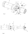
figure 1 ; - figure 5
- a second possible embodiment of the invention in a three-dimensional view;
- figure 6
- a lateral plan view of the embodiment according to FIG
figure 5 .
Bei der Ausgestaltung gemäß den
Im Einzelnen ist die Kupplungsstange 1 über das sphärische elastische Lager 6 an dem Lagerbock 4 beweglich angeschlossen. Die Beweglichkeit wird durch den gelenkigen Anschluss um die Vertikalachse 5 und ferner durch die Elastizität des Lagers 6 erreicht.In detail, the
Beispielsweise weist der Lagerbock 4 eine rohrförmige Struktur mit sich einer anschließenden Gelenkgabel auf und die Kupplungsstange 1 weist im Bereich des zweiten axialen Endes einen Lagerring auf, in welchen das Lager 6 eingebracht ist, wobei ferner ein Zapfen 18 vorgesehen ist, der durch die Gelenkgabel und das Lager 6 geführt ist, um die gewünschte Drehbeweglichkeit um die Vertikalachse 5 auszubilden.For example, the
Der Lagerbock 4 ist an ein Energieverzehrelement 8 angeschlossen, das koaxial zur Kupplungsstange 1 positioniert ist. Der Lagerbock 4 wird ferner von der Grundplatte 9 über seinem äußeren Umfang umschlossen, derart, dass in einem Crashfall der Lagerbock 4 und gegebenenfalls die Kupplungsstange 1 in Richtung des Energieverzehrelementes 8 durch die Grundlatte 9 geschoben werden kann.The
Über derselben Vertikalachse 5 ist auch die Abstützstruktur 7 gelenkig am Lagerbock 4 angeschlossen, hier ebenfalls mittels des Zapfens 18. Im gezeigten Ausführungsbeispiel weist hierfür die Abstützstruktur 7 einen Träger 10 auf, der eine um die Längsachse 2 geschlossene Grundform mit einer sich axial anschließenden Gelenkgabel 19 aufweist, die in die Gelenkgabel des Lagerbocks 4 eingreift und von dem Zapfen 18 entsprechend durchdrungen wird. Ferner weist der Träger 10 zwei im Bereich des der Gelenkgabel 19 entgegengesetzten axialen Endes angeschlossene seitliche Führungen 11, 12 auf, die mit Hohlzylindern 20, 21 versehen sind und über die die Kupplungsstange 1 von unten abstützende Quertraverse 13 miteinander verbunden sind.The
Auf der Quertraverse 13 stehen zwei Säulen 14, 15, beispielsweise ausgebildet durch Schrauben, welche von den Hohlzylindern 20, 21 umschlossen werden und gegenüber den Hohlzylindern 20, 21 elastisch abgestützt sind, sodass ein elastisches Auf- und Abfedern der Kupplungsstange 1 gegenüber dem Träger 10 ermöglicht wird.On the
In der
Bei der Ausgestaltung gemäß den
Bei dieser Ausgestaltung passt der Träger 10 somit nicht durch die Öffnung der Grundplatte 9, sodass in einem Crashfall das Kupplungsrohr 1 von der Abstützstruktur 7, hier der Quertraverse 13 getrennt wird. Entsprechend ist es nicht notwendig die seitlichen Führungen 11, 12 bzw. die Hohlzylinder 20, 21 vom Träger 10 zu trennen.In this embodiment, the
- 11
- Kupplungsstangeclutch rod
- 22
- Längsachselongitudinal axis
- 33
- Kupplungskopfcoupling head
- 44
- Lagerbockbearing block
- 55
- Vertikalachsevertical axis
- 66
- Lagercamp
- 77
- Abstützstruktursupport structure
- 88th
- Energieverzehrelementenergy absorbing element
- 99
- Grundplattebase plate
- 1010
- Trägercarrier
- 1111
- seitlicheFührunglateral guide
- 1212
- seitliche Führunglateral guidance
- 1313
- Quertraversecrossbeam
- 1414
- Säulepillar
- 1515
- Säulepillar
- 1616
- Stützfedersupport spring
- 1717
- zusätzlicher Lagerbockadditional bearing block
- 1818
- Zapfencones
- 1919
- Gelenkgabelarticulated fork
- 2020
- Hohlzylinderhollow cylinder
- 2121
- Hohlzylinderhollow cylinder
Claims (12)
- Coupling arrangement, in particular for a rail vehicle,1.1 having a coupling rod (1) which extends along a longitudinal axis (2) and which carries a coupling head (3) in the region of a first axial end;1.2 having a bearing block (4), to which the coupling rod (1) is connected by a second axial end arranged opposite to the first axial end such that it can articulate about a vertical axis (5);1.3 having a bearing (6) between the bearing block (4) and the coupling rod (1), which is configured to permit at least limited movement between the coupling rod (1) and the bearing block (4) in the vertical direction, and/or having a mounting of the bearing block (4) that is movable in the vertical direction;1.4 having a supporting structure (7) which supports the coupling rod (1) resiliently against the movement in the vertical direction; wherein1.5 the supporting structure (7) is positioned in the vertical direction at least predominantly at the height of the bearing block (4) and/or the coupling rod (1), substantially coaxially with the longitudinal axis (2), and the supporting structure (7) above and below the coupling rod (1) and/or the bearing (6) is connected to the bearing block (4) in an articulated manner and is carried by the latter;characterized in thatthe bearing block (4) has an articulated fork, a pin (18) being provided, which is led through the articulated fork and the bearing (6), and the supporting structure (7) has a yoke (10), which has a closed outline about the longitudinal axis (2) with an axially adjacent articulated fork (19), which engages in the articulated fork of the bearing block (4) and is penetrated by the pin (18), and the yoke (10) has two lateral guides (11, 12) connected in the region of the axial end opposite to the articulated fork (19), wherein the lateral guides (11, 12) enclose the coupling rod (1) between them in the horizontal direction and are connected to each other by a crossmember (13) extending underneath the coupling rod (1), supporting the coupling rod (1) from below and connected to the lateral guides (11, 12) resiliently, at least in the vertical direction.
- Coupling arrangement, in particular for a rail vehicle,2.1 having a coupling rod (1) which extends along a longitudinal axis (2) and which carries a coupling head (3) in the region of a first axial end;2.2 having a bearing block (4), to which the coupling rod (1) is connected by a second axial end arranged opposite to the first axial end such that it can articulate about a vertical axis (5);2.3 having a bearing (6) between the bearing block (4) and the coupling rod (1), which is configured to permit at least limited movement between the coupling rod (1) and the bearing block (4) in the vertical direction, and/or having a mounting of the bearing block (4) that is movable in the vertical direction;2.4 having a supporting structure (7) which supports the coupling rod (1) resiliently against the movement in the vertical direction; wherein2.5 the supporting structure (7) is positioned in the vertical direction at least predominantly at the height of the bearing block (4) and/or the coupling rod (1), coaxially with the longitudinal axis (2),characterized in that2.6 the bearing block (4) is connected axially to a deformable energy absorbing element (8), and in that a base plate (9) enclosing the bearing block (4) and/or the energy absorbing element (8) is provided, which is configured to connect the coupling arrangement in a supportive manner to a carriage body of the rail vehicle or another vehicle component, wherein the supporting structure (7) above and below the coupling rod (1) and/or the bearing (6) is connected to the base plate (9) in an articulated manner and is carried exclusively by the latter.
- Coupling arrangement according to Claim 1 or 2, characterized in that the supporting structure (7) extends above and below the coupling rod (1) and/or over and under the bearing (6).
- Coupling arrangement according to Claim 1, characterized in that the supporting structure (7) is connected to the bearing block (4) such that it can articulate about the same vertical axis (5) as the coupling rod (1).
- Coupling arrangement according to Claim 2, characterized in that the supporting structure (7) is connected to the base plate (9) such that it can articulate, in particular about the vertical axis (5), and is carried by said base plate.
- Coupling arrangement according to one of Claims 1, 3 or 4, characterized in that the supporting structure (7) has a yoke (10) enclosing the coupling rod (1) over its circumference and at least two lateral guides (11, 12) connected to the yoke (10), wherein the lateral guides (11, 12) enclose the coupling rod (1) between them in the horizontal direction.
- Coupling arrangement according to Claim 6, characterized in that the lateral guides (11, 12) are connected to each other by a crossmember (13) extending underneath the coupling rod (1) and supporting the coupling rod (1) from below.
- Coupling arrangement according to Claim 7, characterized in that the lateral guides (11, 12) are connected rigidly to the yoke (10) and the crossmember (13) is connected to the lateral guides (11, 12) resiliently, at least in the vertical direction.
- Coupling arrangement according to Claim 1 or 8, characterized in that two pillars (14, 15) standing vertically on the crossmember (13) are provided, are enclosed over their circumference by the lateral guides (11, 12) and are carried by means of a spring element in the lateral guides (11, 12).
- Coupling arrangement according to one of Claims 1 to 9, characterized in that the bearing (6) is formed as a spherical bearing.
- Coupling arrangement according to one of Claims 1 to 10, characterized in that the bearing (6) is formed as a resilient bearing, in particular as a rubber-metal bearing.
- Coupling arrangement according to one of Claims 1 to 11, characterized in that the coupling arrangement is free of a supporting structure which is carried exclusively on one side outside the coupling rod (1) in an articulated manner, in particular on the bearing block (4) or the base plate (9), in the radial direction of the coupling rod (1).
Applications Claiming Priority (2)
| Application Number | Priority Date | Filing Date | Title |
|---|---|---|---|
| DE102016125087.2A DE102016125087A1 (en) | 2016-12-21 | 2016-12-21 | Coupling arrangement, in particular for a rail vehicle |
| PCT/EP2017/076686 WO2018114087A1 (en) | 2016-12-21 | 2017-10-19 | Coupling arrangement, in particular for a rail vehicle |
Publications (2)
| Publication Number | Publication Date |
|---|---|
| EP3558785A1 EP3558785A1 (en) | 2019-10-30 |
| EP3558785B1 true EP3558785B1 (en) | 2023-04-19 |
Family
ID=60138380
Family Applications (1)
| Application Number | Title | Priority Date | Filing Date |
|---|---|---|---|
| EP17786910.4A Active EP3558785B1 (en) | 2016-12-21 | 2017-10-19 | Coupling arrangement, in particular for a rail vehicle |
Country Status (7)
| Country | Link |
|---|---|
| US (1) | US11472448B2 (en) |
| EP (1) | EP3558785B1 (en) |
| CN (1) | CN110072757B (en) |
| DE (1) | DE102016125087A1 (en) |
| HU (1) | HUE062328T2 (en) |
| PL (1) | PL3558785T3 (en) |
| WO (1) | WO2018114087A1 (en) |
Families Citing this family (2)
| Publication number | Priority date | Publication date | Assignee | Title |
|---|---|---|---|---|
| CN110304097B (en) * | 2019-07-25 | 2020-05-05 | 中车青岛四方车辆研究所有限公司 | Buffer device, coupler and buffer device and rail train |
| CN113071528A (en) * | 2021-04-26 | 2021-07-06 | 大连交通大学 | Flexible wear-resistant coupler joist device |
Citations (1)
| Publication number | Priority date | Publication date | Assignee | Title |
|---|---|---|---|---|
| EP2862777B1 (en) * | 2012-06-13 | 2019-06-19 | CRRC Qingdao Sifang Rolling Stock Research Institute Co., Ltd. | Front installed suspension system having overload protection |
Family Cites Families (8)
| Publication number | Priority date | Publication date | Assignee | Title |
|---|---|---|---|---|
| DE3015291A1 (en) * | 1980-04-21 | 1982-01-21 | Bergische Stahl-Industrie, 5630 Remscheid | MEDIUM BUFFER CLUTCH, ESPECIALLY FOR RAIL VEHICLES |
| DE502005001252D1 (en) * | 2005-05-03 | 2007-09-27 | Voith Turbo Scharfenberg Gmbh | Central buffer coupling for rail vehicles |
| PT1955918E (en) * | 2007-02-08 | 2009-07-16 | Voith Patent Gmbh | Automatic central buffer coupling |
| JP5307104B2 (en) * | 2010-10-14 | 2013-10-02 | 株式会社日本製鋼所 | Connecting device |
| CN102632906B (en) * | 2012-04-17 | 2014-09-10 | 青岛思锐科技有限公司 | Compact buffer with overload protection |
| CN107531258A (en) * | 2015-04-29 | 2018-01-02 | 福伊特专利有限公司 | For the articulated section for being connected the end regions of the cabin side of coupling device bar with compartment hinge type |
| CN105083318B (en) | 2015-09-28 | 2016-09-14 | 青岛思锐科技有限公司 | Hitch spring vertical supporting device |
| CH716577B1 (en) * | 2019-09-12 | 2023-08-31 | Faiveley Transp Schwab Ag | Linkage device for a coupling, in particular of a rail vehicle. |
-
2016
- 2016-12-21 DE DE102016125087.2A patent/DE102016125087A1/en active Pending
-
2017
- 2017-10-19 EP EP17786910.4A patent/EP3558785B1/en active Active
- 2017-10-19 CN CN201780077962.9A patent/CN110072757B/en active Active
- 2017-10-19 HU HUE17786910A patent/HUE062328T2/en unknown
- 2017-10-19 WO PCT/EP2017/076686 patent/WO2018114087A1/en unknown
- 2017-10-19 PL PL17786910.4T patent/PL3558785T3/en unknown
-
2019
- 2019-06-20 US US16/447,534 patent/US11472448B2/en active Active
Patent Citations (1)
| Publication number | Priority date | Publication date | Assignee | Title |
|---|---|---|---|---|
| EP2862777B1 (en) * | 2012-06-13 | 2019-06-19 | CRRC Qingdao Sifang Rolling Stock Research Institute Co., Ltd. | Front installed suspension system having overload protection |
Also Published As
| Publication number | Publication date |
|---|---|
| DE102016125087A1 (en) | 2018-06-21 |
| EP3558785A1 (en) | 2019-10-30 |
| HUE062328T2 (en) | 2023-10-28 |
| US11472448B2 (en) | 2022-10-18 |
| WO2018114087A1 (en) | 2018-06-28 |
| CN110072757A (en) | 2019-07-30 |
| PL3558785T3 (en) | 2023-08-07 |
| CN110072757B (en) | 2021-08-31 |
| US20190300027A1 (en) | 2019-10-03 |
Similar Documents
| Publication | Publication Date | Title |
|---|---|---|
| EP3303098B1 (en) | Wheel suspension system | |
| DE102015217727A1 (en) | STOP CAP | |
| EP1916180A2 (en) | Coupling between two articulated vehicle parts, e.g. for an articulated vehicle | |
| DE102017215112A1 (en) | Vibration damper in the suspension of a vehicle | |
| EP3558785B1 (en) | Coupling arrangement, in particular for a rail vehicle | |
| WO2017102197A1 (en) | Engine mount pendulum support device | |
| DE102009030633A1 (en) | Axle connection for spring-loaded vehicle axles for e.g. lorry-trailer, has plate with opening that widens toward plate outer side to lug, where transmission of supporting forces of nut opposite plate exclusively takes place in lug | |
| DE4129797C2 (en) | Vibration damper | |
| EP3303018B1 (en) | Axle assembly for a vehicle | |
| EP2780182B1 (en) | Rigid axle with air suspension | |
| EP1897776B1 (en) | Bogie | |
| DE10019643C2 (en) | Suspension arrangement for a dynamically stressed exhaust system | |
| DE10338625A1 (en) | Individual wheel suspension for vehicle axle has one cross rod per wheel curved between two articulated points on vehicle structure to help break down front impact crash forces | |
| DE3239006A1 (en) | VEHICLE WITH A BODY PART WHICH CAN BE SWIVELED A HORIZONTAL AXLE AND IS SUPPORTED BY A HYDROPNEUMATIC SUSPENSION | |
| DE3405173A1 (en) | Wheel suspension for motor vehicles | |
| DE102018006572B4 (en) | Vehicle suspension arrangement for at least one wheel axle | |
| DE102020123061B4 (en) | Spring element and vehicle seat with spring element | |
| EP3130489A2 (en) | Wheel suspension for a motor vehicle | |
| DE102017200867B4 (en) | Steering arrangement for a vehicle | |
| DE60003244T2 (en) | MacPherson-type vehicle suspension device | |
| DE1655104B2 (en) | Device for the articulation of an auxiliary frame serving as an axle carrier on the body or the main frame of a vehicle | |
| EP3031636A1 (en) | Wheel carrier module | |
| EP2230107B1 (en) | Wheel suspension for an off-road vehicle | |
| WO2014202299A1 (en) | Wheel suspension for a motor vehicle | |
| DE19748250A1 (en) | Rigid axle arrangement for motor vehicle |
Legal Events
| Date | Code | Title | Description |
|---|---|---|---|
| STAA | Information on the status of an ep patent application or granted ep patent |
Free format text: STATUS: UNKNOWN |
|
| STAA | Information on the status of an ep patent application or granted ep patent |
Free format text: STATUS: THE INTERNATIONAL PUBLICATION HAS BEEN MADE |
|
| PUAI | Public reference made under article 153(3) epc to a published international application that has entered the european phase |
Free format text: ORIGINAL CODE: 0009012 |
|
| STAA | Information on the status of an ep patent application or granted ep patent |
Free format text: STATUS: REQUEST FOR EXAMINATION WAS MADE |
|
| 17P | Request for examination filed |
Effective date: 20190722 |
|
| AK | Designated contracting states |
Kind code of ref document: A1 Designated state(s): AL AT BE BG CH CY CZ DE DK EE ES FI FR GB GR HR HU IE IS IT LI LT LU LV MC MK MT NL NO PL PT RO RS SE SI SK SM TR |
|
| AX | Request for extension of the european patent |
Extension state: BA ME |
|
| RIN1 | Information on inventor provided before grant (corrected) |
Inventor name: KOLSHORN, KAY UWE Inventor name: SCHIPMANN, RALF Inventor name: JOHANNSEN, ERIK |
|
| RAP1 | Party data changed (applicant data changed or rights of an application transferred) |
Owner name: VOITH PATENT GMBH |
|
| DAV | Request for validation of the european patent (deleted) | ||
| DAX | Request for extension of the european patent (deleted) | ||
| STAA | Information on the status of an ep patent application or granted ep patent |
Free format text: STATUS: EXAMINATION IS IN PROGRESS |
|
| 17Q | First examination report despatched |
Effective date: 20210426 |
|
| STAA | Information on the status of an ep patent application or granted ep patent |
Free format text: STATUS: EXAMINATION IS IN PROGRESS |
|
| GRAP | Despatch of communication of intention to grant a patent |
Free format text: ORIGINAL CODE: EPIDOSNIGR1 |
|
| STAA | Information on the status of an ep patent application or granted ep patent |
Free format text: STATUS: GRANT OF PATENT IS INTENDED |
|
| INTG | Intention to grant announced |
Effective date: 20221108 |
|
| GRAS | Grant fee paid |
Free format text: ORIGINAL CODE: EPIDOSNIGR3 |
|
| GRAA | (expected) grant |
Free format text: ORIGINAL CODE: 0009210 |
|
| STAA | Information on the status of an ep patent application or granted ep patent |
Free format text: STATUS: THE PATENT HAS BEEN GRANTED |
|
| AK | Designated contracting states |
Kind code of ref document: B1 Designated state(s): AL AT BE BG CH CY CZ DE DK EE ES FI FR GB GR HR HU IE IS IT LI LT LU LV MC MK MT NL NO PL PT RO RS SE SI SK SM TR |
|
| REG | Reference to a national code |
Ref country code: GB Ref legal event code: FG4D Free format text: NOT ENGLISH |
|
| REG | Reference to a national code |
Ref country code: DE Ref legal event code: R096 Ref document number: 502017014638 Country of ref document: DE |
|
| REG | Reference to a national code |
Ref country code: CH Ref legal event code: EP |
|
| REG | Reference to a national code |
Ref country code: IE Ref legal event code: FG4D Free format text: LANGUAGE OF EP DOCUMENT: GERMAN |
|
| REG | Reference to a national code |
Ref country code: AT Ref legal event code: REF Ref document number: 1560996 Country of ref document: AT Kind code of ref document: T Effective date: 20230515 |
|
| P01 | Opt-out of the competence of the unified patent court (upc) registered |
Effective date: 20230613 |
|
| REG | Reference to a national code |
Ref country code: SE Ref legal event code: TRGR |
|
| REG | Reference to a national code |
Ref country code: LT Ref legal event code: MG9D |
|
| REG | Reference to a national code |
Ref country code: NL Ref legal event code: MP Effective date: 20230419 |
|
| PG25 | Lapsed in a contracting state [announced via postgrant information from national office to epo] |
Ref country code: NL Free format text: LAPSE BECAUSE OF FAILURE TO SUBMIT A TRANSLATION OF THE DESCRIPTION OR TO PAY THE FEE WITHIN THE PRESCRIBED TIME-LIMIT Effective date: 20230419 |
|
| REG | Reference to a national code |
Ref country code: HU Ref legal event code: AG4A Ref document number: E062328 Country of ref document: HU |
|
| PG25 | Lapsed in a contracting state [announced via postgrant information from national office to epo] |
Ref country code: PT Free format text: LAPSE BECAUSE OF FAILURE TO SUBMIT A TRANSLATION OF THE DESCRIPTION OR TO PAY THE FEE WITHIN THE PRESCRIBED TIME-LIMIT Effective date: 20230821 Ref country code: NO Free format text: LAPSE BECAUSE OF FAILURE TO SUBMIT A TRANSLATION OF THE DESCRIPTION OR TO PAY THE FEE WITHIN THE PRESCRIBED TIME-LIMIT Effective date: 20230719 Ref country code: ES Free format text: LAPSE BECAUSE OF FAILURE TO SUBMIT A TRANSLATION OF THE DESCRIPTION OR TO PAY THE FEE WITHIN THE PRESCRIBED TIME-LIMIT Effective date: 20230419 |
|
| PG25 | Lapsed in a contracting state [announced via postgrant information from national office to epo] |
Ref country code: RS Free format text: LAPSE BECAUSE OF FAILURE TO SUBMIT A TRANSLATION OF THE DESCRIPTION OR TO PAY THE FEE WITHIN THE PRESCRIBED TIME-LIMIT Effective date: 20230419 Ref country code: LV Free format text: LAPSE BECAUSE OF FAILURE TO SUBMIT A TRANSLATION OF THE DESCRIPTION OR TO PAY THE FEE WITHIN THE PRESCRIBED TIME-LIMIT Effective date: 20230419 Ref country code: LT Free format text: LAPSE BECAUSE OF FAILURE TO SUBMIT A TRANSLATION OF THE DESCRIPTION OR TO PAY THE FEE WITHIN THE PRESCRIBED TIME-LIMIT Effective date: 20230419 Ref country code: IS Free format text: LAPSE BECAUSE OF FAILURE TO SUBMIT A TRANSLATION OF THE DESCRIPTION OR TO PAY THE FEE WITHIN THE PRESCRIBED TIME-LIMIT Effective date: 20230819 Ref country code: HR Free format text: LAPSE BECAUSE OF FAILURE TO SUBMIT A TRANSLATION OF THE DESCRIPTION OR TO PAY THE FEE WITHIN THE PRESCRIBED TIME-LIMIT Effective date: 20230419 Ref country code: GR Free format text: LAPSE BECAUSE OF FAILURE TO SUBMIT A TRANSLATION OF THE DESCRIPTION OR TO PAY THE FEE WITHIN THE PRESCRIBED TIME-LIMIT Effective date: 20230720 Ref country code: AL Free format text: LAPSE BECAUSE OF FAILURE TO SUBMIT A TRANSLATION OF THE DESCRIPTION OR TO PAY THE FEE WITHIN THE PRESCRIBED TIME-LIMIT Effective date: 20230419 |
|
| PG25 | Lapsed in a contracting state [announced via postgrant information from national office to epo] |
Ref country code: FI Free format text: LAPSE BECAUSE OF FAILURE TO SUBMIT A TRANSLATION OF THE DESCRIPTION OR TO PAY THE FEE WITHIN THE PRESCRIBED TIME-LIMIT Effective date: 20230419 |
|
| PG25 | Lapsed in a contracting state [announced via postgrant information from national office to epo] |
Ref country code: SK Free format text: LAPSE BECAUSE OF FAILURE TO SUBMIT A TRANSLATION OF THE DESCRIPTION OR TO PAY THE FEE WITHIN THE PRESCRIBED TIME-LIMIT Effective date: 20230419 |
|
| REG | Reference to a national code |
Ref country code: DE Ref legal event code: R097 Ref document number: 502017014638 Country of ref document: DE |
|
| PG25 | Lapsed in a contracting state [announced via postgrant information from national office to epo] |
Ref country code: SM Free format text: LAPSE BECAUSE OF FAILURE TO SUBMIT A TRANSLATION OF THE DESCRIPTION OR TO PAY THE FEE WITHIN THE PRESCRIBED TIME-LIMIT Effective date: 20230419 Ref country code: SK Free format text: LAPSE BECAUSE OF FAILURE TO SUBMIT A TRANSLATION OF THE DESCRIPTION OR TO PAY THE FEE WITHIN THE PRESCRIBED TIME-LIMIT Effective date: 20230419 Ref country code: RO Free format text: LAPSE BECAUSE OF FAILURE TO SUBMIT A TRANSLATION OF THE DESCRIPTION OR TO PAY THE FEE WITHIN THE PRESCRIBED TIME-LIMIT Effective date: 20230419 Ref country code: EE Free format text: LAPSE BECAUSE OF FAILURE TO SUBMIT A TRANSLATION OF THE DESCRIPTION OR TO PAY THE FEE WITHIN THE PRESCRIBED TIME-LIMIT Effective date: 20230419 Ref country code: DK Free format text: LAPSE BECAUSE OF FAILURE TO SUBMIT A TRANSLATION OF THE DESCRIPTION OR TO PAY THE FEE WITHIN THE PRESCRIBED TIME-LIMIT Effective date: 20230419 Ref country code: CZ Free format text: LAPSE BECAUSE OF FAILURE TO SUBMIT A TRANSLATION OF THE DESCRIPTION OR TO PAY THE FEE WITHIN THE PRESCRIBED TIME-LIMIT Effective date: 20230419 |
|
| PGFP | Annual fee paid to national office [announced via postgrant information from national office to epo] |
Ref country code: SE Payment date: 20231019 Year of fee payment: 7 Ref country code: HU Payment date: 20231024 Year of fee payment: 7 Ref country code: DE Payment date: 20231020 Year of fee payment: 7 |
|
| PLBE | No opposition filed within time limit |
Free format text: ORIGINAL CODE: 0009261 |
|
| STAA | Information on the status of an ep patent application or granted ep patent |
Free format text: STATUS: NO OPPOSITION FILED WITHIN TIME LIMIT |
|
| PGFP | Annual fee paid to national office [announced via postgrant information from national office to epo] |
Ref country code: PL Payment date: 20231006 Year of fee payment: 7 |
|
| 26N | No opposition filed |
Effective date: 20240122 |