EP3558573B1 - Bohrkrone mit einem spiralrohrförmigen bohrschaft und verfahren zur herstellung eines spiralrohrförmigen bohrschaftes für eine bohrkrone - Google Patents
Bohrkrone mit einem spiralrohrförmigen bohrschaft und verfahren zur herstellung eines spiralrohrförmigen bohrschaftes für eine bohrkrone Download PDFInfo
- Publication number
- EP3558573B1 EP3558573B1 EP17804205.7A EP17804205A EP3558573B1 EP 3558573 B1 EP3558573 B1 EP 3558573B1 EP 17804205 A EP17804205 A EP 17804205A EP 3558573 B1 EP3558573 B1 EP 3558573B1
- Authority
- EP
- European Patent Office
- Prior art keywords
- spiral
- drill
- drill shaft
- strip
- shaped
- Prior art date
- Legal status (The legal status is an assumption and is not a legal conclusion. Google has not performed a legal analysis and makes no representation as to the accuracy of the status listed.)
- Active
Links
Images


Classifications
-
- B—PERFORMING OPERATIONS; TRANSPORTING
- B23—MACHINE TOOLS; METAL-WORKING NOT OTHERWISE PROVIDED FOR
- B23P—METAL-WORKING NOT OTHERWISE PROVIDED FOR; COMBINED OPERATIONS; UNIVERSAL MACHINE TOOLS
- B23P15/00—Making specific metal objects by operations not covered by a single other subclass or a group in this subclass
- B23P15/28—Making specific metal objects by operations not covered by a single other subclass or a group in this subclass cutting tools
-
- B—PERFORMING OPERATIONS; TRANSPORTING
- B23—MACHINE TOOLS; METAL-WORKING NOT OTHERWISE PROVIDED FOR
- B23B—TURNING; BORING
- B23B51/00—Tools for drilling machines
- B23B51/04—Drills for trepanning
-
- B—PERFORMING OPERATIONS; TRANSPORTING
- B23—MACHINE TOOLS; METAL-WORKING NOT OTHERWISE PROVIDED FOR
- B23B—TURNING; BORING
- B23B2240/00—Details of connections of tools or workpieces
- B23B2240/04—Bayonet connections
-
- B—PERFORMING OPERATIONS; TRANSPORTING
- B23—MACHINE TOOLS; METAL-WORKING NOT OTHERWISE PROVIDED FOR
- B23B—TURNING; BORING
- B23B2240/00—Details of connections of tools or workpieces
- B23B2240/16—Welded connections
-
- B—PERFORMING OPERATIONS; TRANSPORTING
- B23—MACHINE TOOLS; METAL-WORKING NOT OTHERWISE PROVIDED FOR
- B23B—TURNING; BORING
- B23B2251/00—Details of tools for drilling machines
- B23B2251/40—Flutes, i.e. chip conveying grooves
- B23B2251/408—Spiral grooves
-
- B—PERFORMING OPERATIONS; TRANSPORTING
- B23—MACHINE TOOLS; METAL-WORKING NOT OTHERWISE PROVIDED FOR
- B23K—SOLDERING OR UNSOLDERING; WELDING; CLADDING OR PLATING BY SOLDERING OR WELDING; CUTTING BY APPLYING HEAT LOCALLY, e.g. FLAME CUTTING; WORKING BY LASER BEAM
- B23K2101/00—Articles made by soldering, welding or cutting
- B23K2101/04—Tubular or hollow articles
- B23K2101/06—Tubes
-
- B—PERFORMING OPERATIONS; TRANSPORTING
- B23—MACHINE TOOLS; METAL-WORKING NOT OTHERWISE PROVIDED FOR
- B23K—SOLDERING OR UNSOLDERING; WELDING; CLADDING OR PLATING BY SOLDERING OR WELDING; CUTTING BY APPLYING HEAT LOCALLY, e.g. FLAME CUTTING; WORKING BY LASER BEAM
- B23K2101/00—Articles made by soldering, welding or cutting
- B23K2101/20—Tools
-
- B—PERFORMING OPERATIONS; TRANSPORTING
- B23—MACHINE TOOLS; METAL-WORKING NOT OTHERWISE PROVIDED FOR
- B23K—SOLDERING OR UNSOLDERING; WELDING; CLADDING OR PLATING BY SOLDERING OR WELDING; CUTTING BY APPLYING HEAT LOCALLY, e.g. FLAME CUTTING; WORKING BY LASER BEAM
- B23K31/00—Processes relevant to this subclass, specially adapted for particular articles or purposes, but not covered by only one of the preceding main groups
- B23K31/02—Processes relevant to this subclass, specially adapted for particular articles or purposes, but not covered by only one of the preceding main groups relating to soldering or welding
- B23K31/027—Making tubes with soldering or welding
Definitions
- the present invention relates to a drill bit with a spiral-tubular drill shaft according to the preamble of claim 1 and a method for producing a spiral-tubular drill shaft for such a drill bit according to the preamble of claim 13.
- Drill bits consist of several drill bit sections, which are designed as a cutting section and a drill shaft section.
- the cutting section comprises a ring section and one or more cutting segments which are welded, soldered, screwed to the ring section or fastened to the ring section in another suitable type of fastening.
- the drill shaft section comprises a tubular drill shaft, a cover and an insertion end via which the drill bit is fastened in the tool holder of a core drilling device.
- the drill shank is made from a tubular material or from a flat strip material that is formed into a tube and joined at the strip edges by longitudinal seam welding.
- the cutting section and the drill shaft section are detachably or non-detachably connected by means of a connecting device.
- the ring section of the cutting section and the drill shaft can be designed monolithically; alternatively, the ring section can be materially connected to the drill shaft.
- a drill bit produces a drill core with a core diameter and a borehole with a borehole diameter in a workpiece.
- the cutting segments form a cutting ring with an inside diameter that corresponds to the core diameter and an outside diameter that corresponds to the bore hole diameter.
- Core bits for wet drilling (wet core bits) differ in structure from core bits for dry drilling (dry core bits).
- Wet drilling requires a coolant and flushing fluid that cools the cutting segments of the drill bit as a cooling fluid and cuttings as the flushing fluid transported from the borehole. Clean cooling and flushing fluid is usually supplied via an internal gap between the drill core and the drill shaft, and used cooling and flushing fluid mixed with cuttings is discharged through an external gap between the drill shaft and the drill hole.
- drill bits without an inner gap and / or without an outer gap are known, with the cooling and flushing liquid being transported via special transport channels in the outside of the drill shaft.
- the drill shank has a large contact surface with the drill core on the inside and a large contact surface with the borehole on the outside.
- the large contact surfaces on the inside and outside of the drill shaft lead to strong friction. The greater the friction between the drill shaft and the drill core or the drill shaft and the borehole, the lower the drilling progress of the drill bit with the same performance of the core drill and the lower the service life of the drill shaft.
- a drill bit according to the preamble of claim 1 is from EP 2 745 966 A1 known.
- the object of the present invention is to further develop a drill bit in such a way that the stability and the guidance of the drill shaft are improved during drilling, in particular during wet drilling with a cooling and flushing liquid.
- the drilling progress of the drill bit should be increased and / or the service life of the drill shaft extended.
- the drill bit is characterized in that the tubular drill shaft is designed as a welded spiral tube, with one drill shaft being the welded Spiral tube is formed, is also referred to as a spiral tube-shaped drill shaft.
- a welded spiral tube has at least one spiral-shaped connecting weld seam which acts as a stiffening element for the drill shaft and increases the rigidity of the drill shaft compared to a longitudinally welded or tubular drill shaft of the same wall thickness.
- band materials with smaller wall thicknesses can be used, which have the same rigidity in the finished drill shaft as a longitudinally welded or tubular drill shaft.
- the use of a welded spiral tube as a drill shaft either increases the rigidity of the drill shaft during drilling and / or reduces the weight of the drill shaft.
- a drill shaft with a higher rigidity improves the stability of the drill shaft when drilling.
- the drill bit according to the invention has a cutting section with one or more cutting segments, a drill shaft section with the spiral-shaped drill shaft and a connecting device which connects the cutting section and drill shaft section to one another in a detachable or non-detachable manner.
- the cutting section comprises a single cutting segment, which forms a closed cutting ring, or a plurality of cutting segments, which are arranged in a ring and form a cutting ring with gaps.
- the cutting section comprises, in addition to the cutting segments, an annular section which can be designed in the shape of a spiral tube or a tube.
- the connection device is designed as a detachable or non-detachable connection device.
- a connection device is referred to as detachable if the connection can be detached by the user in a non-destructive manner, such as a plug connection, a pin connection or a threaded connection.
- a connection device is referred to as non-detachable if the user can only detach the connection by destroying the connection means, such as a soldered connection, a welded connection or an adhesive connection.
- the tubular drill shank is preferably formed from N, N 1 strip materials, the band edges of the band materials being firmly connected by means of N, N 1 spiral welded seams.
- the strip materials are continuously shaped into spiral tubes with a constant radius of curvature in a molding machine and then welded to the edges of the strip in a welding machine.
- processes in common molding and welding systems and processes in separate molding and welding systems are known.
- the N, N 1 strip materials are designed as flat sheets with a constant sheet thickness.
- the spiral tube-shaped drill shank is made from flat sheet metal that has a constant sheet thickness and width.
- the flat metal sheets are formed into a spiral tube and connected to one another by means of spiral welded seams at the edges of the strip.
- the formed strip material has a constant wall thickness, which corresponds to the sheet thickness of the flat sheets.
- the geometry of the spiral weld seams can be influenced by the process control during welding. By supplying a suture material, spiral-shaped connection weld seams can be produced which protrude on the inside of the drill shaft, the outside of the drill shaft or on the inside and outside of the drill shaft relative to the formed band material.
- the N, N ⁇ 1 strip materials are designed as flat metal sheets with at least one depression.
- the depressions are created in the sheet metal before the strip material is formed into a spiral tube and serve as a transport channel for the necessary cooling and rinsing liquid during wet drilling.
- a cooling and flushing fluid is required which, as a cooling fluid, cools the cutting segments and, as a flushing fluid, transports cuttings out of the borehole.
- the number of recesses, the geometry of the recesses and the arrangement of the recesses on the inside and / or outside of the drill shaft can be adapted to the amount of liquid in the cooling and rinsing liquid.
- the depressions provided on the inside of the drill shaft serve to supply clean cooling and flushing liquid and the depressions provided on the outside of the drill shaft serve to discharge used cooling and flushing liquid that has been mixed with drill cuttings. Since the depressions in the drill bit according to the invention are produced before the strip material is reshaped, depressions can be produced on the inside of the drill shaft with little manufacturing effort. In known drill shafts, the arrangement of transport channels is limited to the outside of the drill shaft, since in the case of a tubular drill shaft, indentations can only be produced on the inside of the drill shaft with great manufacturing effort.
- the N, N 1 strip materials are designed as profiled sheets with a profile cross-section, the profiled sheets having a sheet thickness and a profile height.
- the spiral tube-shaped drill shank is made from plate-shaped profile sheets.
- the direction of the profile cross-section is defined as the longitudinal direction of the plate-shaped profile sheets.
- Plate-shaped profile sheets are available inexpensively in large numbers with different profile cross-sections and enable an inexpensive production of drill shafts for drill bits.
- the profile cross-section creates indentations on the inside and outside of the drill shaft, through which the cooling and rinsing liquid is transported can be.
- the depressions provided on the inside of the drill shaft serve to supply clean cooling and flushing liquid and the depressions provided on the outside of the drill shaft serve to discharge used cooling and flushing liquid that has been mixed with drill cuttings.
- the geometry of the profile sheet can be adapted to the required amount of liquid in the cooling and rinsing liquid.
- At least one spiral-shaped connecting weld seam of the drill shaft protrudes from the shaped strip material of the spiral tube, the at least one protruding spiral-shaped connecting weld seam containing a suture material.
- a spiral-shaped connection weld seam protruding from the formed strip material of the spiral tube improves the guidance of the drill shaft during drilling.
- the protrusion of the spiral joint weld seam is adjusted so that the spiral joint weld seam is in contact with the drill hole on the outside of the drill shaft and / or with the drill core on the inside of the drill shaft. Due to the protruding spiral-shaped connection weld seam, the drill shank has a small contact area with the drill core and the drill hole and generates little friction.
- the spiral connection weld seam can protrude on an inside of the drill shaft, on an outside of the drill shaft or on an inside and outside of the drill shaft with respect to the shaped strip material of the spiral tube.
- a suture material is required in order to produce an overhang of the spiral joint weld seam.
- the suture material can be wire-shaped, band-shaped or powder-shaped.
- a spiral-shaped connection weld seam protruding from the formed strip material of the spiral tube can improve the transport of the cooling and flushing fluid during wet drilling.
- the protruding spiral-shaped connection weld acts as a conveying helix for the cooling and rinsing liquid.
- the protruding spiral-shaped connection weld seam can improve the liquid transport on the inside or the outside of the drill shank. On the inside of the drill shank, clean cooling and rinsing liquid is transported to the processing point and on the outside of the drill shank, used cooling and rinsing liquid mixed with cuttings is transported away.
- the spiral-shaped connecting weld seam acts as a conveying helix for the clean coolant and flushing liquid when the direction of rotation of the drill bit and the direction of the spiral-shaped connecting weld seam on the inside of the drill shaft match
- the spiral-shaped connection weld seam acts as a conveying helix for the used cooling and flushing fluid that has been mixed with cuttings when the direction of rotation of the drill bit and the direction of the spiral-shaped connection weld seam on the outside of the drill shaft match.
- the suture material and the N, N 1 strip materials have the same material properties. If the suture material and the band materials have the same material properties, a smooth transition is created when the band edges are welded and the suture material can bond well with the band material.
- the suture material and the N, N ⁇ 1 band materials have different material properties, the suture material having a higher tensile strength, a higher wear resistance or a higher tensile strength and wear resistance than the band materials.
- the connecting weld seam should enable the drill shaft to be guided during the drilling operation. The smaller the gap between the spiral-shaped connecting weld seam and the drill core on the inside of the drill shank or between the spiral-shaped connecting weld seam and the borehole on the outside, the better the drill shank is guided.
- the spiral connection weld seam Due to friction between the spiral connection weld seam and the drill core on the inside or between the spiral connection weld seam and the borehole on the outside, the spiral connection weld seam can be worn away, whereby the guidance of the drill shaft deteriorates.
- suture material that has a higher tensile strength, a higher wear resistance or a higher tensile strength and wear resistance than the band materials, the properties of the spiral joint weld seam can be influenced, so that the guide of the drill shank over the spiral joint weld seam as possible during the entire service life of the Drill shank is guaranteed.
- the at least one protruding spiral-shaped connection weld seam protrudes on an inside of the drill shank with an inside protrusion ⁇ I with respect to the formed strip material of the spiral tube.
- a spiral weld seam protruding on the inside of the drill shaft enables the drill shaft to be guided over the drill core when drilling with the drill bit.
- a spiral-shaped connection weld seam protruding on the inside of the drill shaft can support the transport of the clean coolant and rinsing fluid to the processing point during wet drilling with the drill bit.
- the spiral joint weld acts as a Conveyor helix for the clean coolant and flushing liquid, if the direction of rotation of the drill bit and the direction of the spiral connection weld on the inside of the drill shaft match.
- the at least one protruding spiral connection weld seam protrudes on an outer side of the drill shank with an outer protrusion ⁇ A with respect to the formed strip material of the spiral tube.
- a spiral-shaped connection weld seam protruding on the outside of the drill shaft enables the drill shaft to be guided over the borehole when drilling with the drill bit.
- a spiral-shaped connection weld seam protruding on the outside of the drill shank can support the removal of the used cooling and flushing fluid that has been mixed with drill cuttings during wet drilling with the drill bit.
- the spiral connection weld acts as a conveyor helix for the used cooling and flushing fluid that has been mixed with drill cuttings, if the direction of rotation of the drill bit and the direction of the spiral connection weld on the outside of the drill shaft match.
- the at least one spiral connection weld seam protrudes on an inside of the drill shaft with an inside protrusion ⁇ I and on an outside of the drill shaft with an outside protrusion ⁇ A with respect to the shaped strip material of the spiral tube.
- a spiral connection weld seam protruding on the inside and outside of the drill shaft enables the drill shaft to be guided both on the inside of the drill shaft over the drill core and on the outside of the drill shaft over the drill hole when drilling with the drill bit.
- the spiral-shaped connection weld seam protruding on the inside and outside of the drill shaft acts during wet drilling on the inside or outside of the drill shaft as a conveying helix for the cooling and flushing liquid.
- the direction of the spiral connection weld defines whether the spiral connection weld supports the transport of fluid on the inside or outside of the drill shaft. If the direction of the spiral connection weld seam and the direction of rotation of the drill bit on the inside of the drill shaft match, the spiral connection weld seam supports the transport of fluid on the inside of the drill shaft. If the direction of the spiral connection weld seam and the direction of rotation of the drill bit on the outside of the drill shaft match, the spiral connection weld seam supports the transport of fluid on the outside of the drill shaft.
- the method for producing a drill shaft for a drill bit characterized in that the N, N ⁇ 1 strip materials are formed into a spiral tube and on the strip edges via N, N ⁇ 1 spiral welded seams be firmly connected.
- the method according to the invention enables an inexpensive production of a spiral tube-shaped drill shaft for a drill bit.
- the strip materials are continuously shaped in a helical shape with a constant radius of curvature into spiral tubes in a molding system and welded to the strip edges in a welding system.
- a suture material is used when connecting the abutting tape edges of the N, N 1 tape materials via the N, N 1 spiral connection weld seams.
- the suture material is, for example, wire-shaped, strip-shaped or powder-shaped and produces a spiral-shaped connection weld seam protruding from the shaped strip material.
- spiral-shaped connection weld seams can be produced that protrude from the formed tape material.
- the protruding spiral-shaped connection weld seams guide the drill shaft during drilling on the inside of the drill shaft over the drill core and / or on the outside of the drill shaft over the drill hole.
- the geometry of the spiral weld seams can be influenced by the process control during welding.
- the suture material can be fed to the inside of the drill shaft, the outside of the drill shaft or the inside and outside of the drill shaft.
- the suture material has a higher tensile strength, a higher wear resistance or a higher tensile strength and wear resistance than the N, N 1 tape materials.
- a first suture material and a second suture material are used when joining the abutting band edges of the N, N ⁇ 1 band materials via the spiral-shaped connection welds, the material properties of the first suture material being different from the material properties of the second suture material.
- the properties of the spiral weld seams can be influenced by the material properties of the suture material used.
- the first suture material can, for example, have the same material properties as the tape materials, so that a more uniform welding process The transition between the band edges is created and the first suture material can connect well to the band material.
- the second suture material can, for example, have a higher tensile strength, a higher wear resistance or a higher tensile strength and wear resistance than the tape materials and improve the properties of the spiral-shaped connection welds.
- FIGN. 1A , B show a first embodiment of a drill bit 10 according to the invention, which is referred to below as the first drill bit 10.
- the first drill bit 10 comprises a cutting section 11 , a drill shaft section 12 and a connecting device 13 which detachably connects the cutting section 11 to the drill shaft section 12. It shows FIG. 1A the first drill bit 10 in the connected state and FIG. 1B the first drill bit 10 in the non-connected state.
- the cutting section 11 comprises a ring section 14 and a plurality of cutting segments 15 which are connected to the ring section 14.
- the cutting segments 15 are arranged in a ring and form a cutting ring with gaps. Instead of several cutting segments 15, the cutting section 11 can also have a single cutting segment designed as a closed cutting ring.
- the cutting segments 15 are welded, soldered, screwed or fastened to the ring section 14 in another suitable type of fastening to the ring section 14.
- the drill shaft section 12 comprises a spiral tubular drill shaft 16 , a cover 17 and an insertion end 18 via which the first drill bit 10 is fastened in a tool holder of a core drilling device.
- the first drill bit 10 is driven by the core drilling device about a drilling axis 19 and moved in a drilling direction 21 parallel to the drilling axis 19 into a workpiece 22 to be machined.
- the first drill bit 10 generated in the workpiece 22 has a core 23 having a core diameter d 1 and a borehole 24 having a borehole diameter d. 2
- the cutting segments 15 form a cutting ring with an inside diameter which corresponds to the core diameter d 1 and an outside diameter which corresponds to the borehole diameter d 2 .
- the connection device 13 is designed as a detachable connection device in the form of a combined plug and pin connection and comprises a first plug connection element 25 , which is connected to the ring section 14, and a second plug connection element 26 , which is connected to the drill shaft 16.
- the first and second plug connection elements 25, 26 form a plug connection and are additionally secured via a pin connection.
- the pin connection comprises a plurality of pin elements 27 which are inserted into T-shaped slots 28 .
- the pin members 27 are attached to an outside of the second connector member 26 and the T-shaped slots 28 are in the first Connector element 25 is provided.
- the cutting section 11 can be connected to the drill shaft section 12 simply and quickly by the operator.
- the cutting section 11 with the first plug connection element 25 is plugged onto the second plug connection element 26 of the drill shaft section 12 in such a way that the pin elements 27 are arranged in the slots 28.
- the cutting section 11 is moved in the drilling direction 21 and then secured by rotating about the drilling axis 19.
- the drill shank 16 is designed as a welded spiral tube which has been manufactured from a strip material 31 in the form of a flat sheet metal by shaping and welding.
- the flat strip material 31 was shaped into a spiral tube and connected at the abutting strip edges by means of a spiral-shaped connecting weld seam 32 .
- the spiral-shaped connecting weld seam 32 acts as a stiffening element for the drill shaft 16 and increases the rigidity of the drill shaft 16 compared to a longitudinally welded or tubular drill shaft of the same wall thickness.
- FIGN. 2A , B shows a longitudinal section through the drill shaft section 12 of the first drill bit 10 of FIG. 1 along section line AA in FIG. 1B ( FIG. 2A ) and a detail of the drill shaft 16 of FIG. 2A in an enlarged view ( FIG. 2 B ).
- the spiral-shaped connection weld seam 32 protrudes from the shaped band material 31 on an outer side 33 and an inner side 34 of the drill shaft 16.
- the protrusion of the spiral connection weld seam 32 on the outside 33 of the drill shaft 16 is referred to as the outside protrusion ⁇ A and the protrusion of the spiral connection weld seam 32 on the inside 34 of the drill shaft 16 is referred to as the inside protrusion ⁇ I.
- a suture material 35 In order to be able to produce a spiral-shaped connection weld seam 32 protruding from the shaped strip material 31 on the outside 33, the inside 34 or the outside and inside 33, 34, a suture material 35 must be used when welding the shaped strip material 31, which has the required volume of material Provides.
- the suture material can be powder-like, wire-like or band-like.
- the material properties of the suture material 35 can be adapted to desired properties of the spiral-shaped connection weld seam 32.
- the spiral connection weld 32 improves the guidance of the drill shaft 16 when drilling with the first drill bit 10, the smaller the gap between the spiral connection weld 32 and the borehole 24 on the outside 33 or between the spiral connection weld 32 and the drill core 23 on the inside 34 is, the better the drill shaft 16 is guided.
- the spiral connection weld seam 32 and the borehole 24 on the outside 33 or between the spiral-shaped connection weld seam 32 and the drill core 23 on the inside 34 the spiral-shaped connection weld seam 32 can be removed, as a result of which the guidance of the drill shank 16 deteriorates.
- the properties of the spiral joint weld seam 32 can be influenced, so that the guidance of the drill shank 16 over the spiral joint weld seam 32 is guaranteed for the entire life of the drill shank 16 if possible .
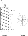
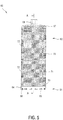
- FIG. 3 shows a second embodiment of a drill bit 40 according to the invention, which is referred to below as a second drill bit 40.
- the second drill bit 40 comprises a cutting section 41, a drill shaft section 42 and a connecting device 43 which connects the cutting section 41 to the drill shaft section 42 in a non-detachable manner.
- the cutting section 41 comprises a plurality of cutting segments 45 which form a cutting ring with an inside diameter which corresponds to the core diameter d 1 and an outside diameter which corresponds to the borehole diameter d 2 .
- the drill shaft section 42 comprises a spiral tube-shaped drill shaft 46 , a cover 47 and an insertion end 48 via which the second drill bit 40 is fastened in a tool holder of a core drilling device.
- the cutting segments 15 are permanently connected to the drill shank 46 via the connecting device 43, the connecting device 43 being designed as a welded connection, soldered connection or adhesive connection. In principle, any connecting device that permanently connects the cutting segments 15 and the drill shaft 46 is suitable.
- the drill shaft 46 is designed in the shape of a spiral tube in the form of a welded spiral tube which has been manufactured from a strip material 51 in the form of a flat sheet metal with recesses by molding and welding.
- the strip material 51 was formed into a spiral tube and connected at the abutting strip edges by means of a spiral-shaped connecting weld seam 52 .
- the second drill bit 40 shows a cutting section 41 with several cutting segments 45, which are non-detachably attached to the drill shaft 46 by means of the connecting device 43.
- the cutting section 41 can also have a single cutting segment designed as a closed cutting ring.
- the cutting section 41 can have an annular section which is arranged between the cutting segments 45 and the drill shaft 46.
- the cutting segments 45 are welded, soldered, screwed or fastened to the ring section in another suitable fastening type and the ring section and the drill shaft 46 are connected detachably or permanently by means of a connecting device.
- the ring section can like that Drill shaft 46 may be formed in the shape of a spiral tube. In the case of thin strip materials, however, the use of tubular ring sections with a constant wall thickness is advisable, since a larger contact surface is available for fastening the cutting segments 45.
- FIGN. 4A , B show a longitudinal section through the second drill bit 40 of FIG. 3 along section line AA in FIG. 3 ( FIG. 4A ) and a detail of the drill shaft 46 of FIG. 4A in an enlarged view ( FIG. 4B ).
- the spiral connection weld seam 52 of the drill shaft 46 protrudes on an outer side 53 of the drill shaft 46 with an external protrusion ⁇ A with respect to the shaped band material 51 and is formed essentially flush with the shaped band material 51 on an inner side 54 of the drill shank 46.
- a suture material 55 is used when welding the shaped strip material 51, which makes the required volume of material available.
- the suture material 55 can be powder-shaped, wire-shaped or band-shaped.
- the properties of the spiral-shaped connecting weld seam 52 can be adapted via the material properties of the suture material 55.
- the suture material 55 can have the same material properties or different material properties as the band material 51. If the suture material 55 and band material 51 have the same material properties, a uniform transition occurs when the band edges are welded and the suture material 55 can bond well to the band material 51.
- the properties of the spiral-shaped connection weld seam 52 can be influenced, so that the guide of the drill shaft 46 over the spiral-shaped connection weld seam 52 as possible during the entire life of the drill shaft 46 is guaranteed.
- the second drill bit 40 shows a spiral tube-shaped drill shaft 46 with a spiral-shaped connection weld seam 52, which protrudes on the outside 53 of the drill shaft 46 with respect to the shaped band material 51 and is essentially flush with the shaped band material 51 on the inside 54 of the drill shaft 46.
- the spiral-shaped connection weld seam 52 can protrude on the inside 54 of the drill shaft 46 with an inside protrusion ⁇ I with respect to the shaped strip material 51 and be formed essentially flush with the shaped strip material 51 on the outside 53 of the drill shaft 46.
- a helical connection weld seam 52 protruding on the inside 54 of the drill shaft 46 enables drilling with the second drill bit 40 a guide of the drill shaft 46 over the drill core 23.
- spiral-shaped connection weld seam 52 protruding on the inside 54 can support the supply of clean coolant and flushing liquid during wet drilling.
- the spiral-shaped connecting weld seam 52 acts as a conveying helix for the clean cooling and flushing liquid when the direction of rotation of the second drill bit 40 and the direction of the spiral-shaped connecting weld seam 52 on the inside 54 of the drill shaft 46 match.
- a cooling and flushing fluid is required which, as a cooling fluid, cools the cutting segments 45 and, as a flushing fluid, transports cuttings away from the borehole 24.
- the spiral-shaped connection weld seam 52 protruding on the outside 53 of the drill shaft 46 can, in addition to guiding the drill shaft 46 over the borehole 24, support the removal of used cooling and flushing liquid that has been mixed with cuttings.
- the spiral connection weld 52 acts as a conveying helix for the used cooling and flushing fluid offset with drill cuttings when the direction of rotation of the second drill bit 40 and the direction of the spiral connection weld 52 on the outside 53 of the drill shaft 46 match.
- first recess 56A, second recess 56B and third recess 56C are arranged on the inside 54 of the drill shaft 46, which are referred to as first recess 56A, second recess 56B and third recess 56C.
- the depressions 56A, 56B, 56C are produced in the sheet metal before the strip material 51 is formed into a spiral tube and serve as a transport channel for the necessary cooling and rinsing liquid during wet drilling with the second drill bit 40.
- the recesses 56A, 56B, 56C are necessary above all when there is a small internal gap between the drill core and the drill shaft.
- the number of depressions 56A, 56B, 56C, the geometry of the depressions 56A, 56B, 56C and the arrangement of the depressions 56A, 56B, 56C on the outside 53 and / or inside 54 of the drill shaft 46 can be adapted to the amount of the cooling and flushing fluid be adjusted.
- the depressions 56A, 56B, 56C provided on the inside 54 of the drill shaft 46 serve to supply clean cooling and flushing fluid and the depressions provided on the outside 53 of the drill shaft 46 can support the removal of used cooling and flushing fluid that has been contaminated with cuttings. Since the depressions 56A, 56B, 56C in the second drill bit 40 are produced before the band material 51 is reshaped, depressions can be produced on the inside 54 of the drill shaft 46 with little manufacturing effort.
- FIG. 5 shows a third embodiment of a drill bit 60 according to the invention, which is referred to below as a third drill bit 60.
- the third drill bit 60 includes one Cutting section 61 , a drill shaft section 62 and a connecting device 63 which permanently connects the cutting section 61 to the drill shaft section 62.
- the cutting section 61 comprises a ring section 64 and a plurality of cutting segments 65 which are welded, soldered, screwed or fastened to the ring section 64 in another suitable fastening type to the ring section 64.
- the drill shaft section 62 comprises a spiral tubular drill shaft 66 , a cover 67 and an insertion end 68 via which the third drill bit 60 is fastened in a tool holder of a core drilling device.
- the drill shank 66 is designed as a welded spiral tube which has been manufactured from a strip material 71 in the form of a corrugated profiled sheet metal by molding and welding.
- the strip material 71 was formed into a spiral tube and connected at the abutting strip edges by means of a spiral-shaped connecting weld seam 72 .
- the spiral-shaped connection weld seam 72 acts as a stiffening element for the drill shank 66.
- FIGN. 6A , B show a longitudinal section through the third drill bit 60 of FIG FIG. 5 along section line AA in FIG. 5 ( FIG. 6A ) and a detail of the drill shaft 66 of FIG. 6A in an enlarged view ( FIG. 6B ).
- the spiral-shaped connecting weld seam 72 of the drill shaft 66 is formed on an outer side 73 of the drill shaft 66 and on an inner side 74 of the drill shaft 66 essentially flush with the shaped strip material 71.
- the profile cross-section of the strip material 71 creates depressions on the outside 73 and inside 74 of the drill shaft 66, through which the cooling and flushing liquid can be transported during wet drilling with the third drill bit 60.
- the depressions provided on the inside 74 of the drill shaft 66 serve to supply clean cooling and rinsing liquid and the depressions provided on the outside 73 of the drill shaft 66 serve to discharge used cooling and rinsing liquid mixed with drill cuttings.
- the geometry of the profile sheet can be adapted to the amount of liquid required for wet drilling.
Landscapes
- Engineering & Computer Science (AREA)
- Mechanical Engineering (AREA)
- Processing Of Stones Or Stones Resemblance Materials (AREA)
- Earth Drilling (AREA)
- Drilling Tools (AREA)
Description
- Die vorliegende Erfindung betrifft eine Bohrkrone mit einem spiralrohrförmigen Bohrschaft gemäß dem Oberbegriff des Anspruchs 1 und ein Verfahren zur Herstellung eines spiralrohrförmigen Bohrschaftes für eine solche Bohrkrone gemäß dem Oberbegriff des Anspruchs 13.
- Bohrkronen bestehen aus mehreren Bohrkronenabschnitten, die als Schneidabschnitt und Bohrschaftabschnitt ausgebildet sind. Der Schneidabschnitt umfasst einen Ringabschnitt und ein oder mehrere Schneidsegmente, die mit dem Ringabschnitt verschweißt, verlötet, verschraubt oder in einer anderen geeigneten Befestigungsart am Ringabschnitt befestigt sind. Der Bohrschaftabschnitt umfasst einen rohrförmigen Bohrschaft, einen Deckel und ein Einsteckende, über das die Bohrkrone in der Werkzeugaufnahme eines Kernbohrgerätes befestigt wird. Der Bohrschaft wird aus einem rohrförmigen Material gefertigt oder aus einem ebenen Bandmaterial, das zu einem Rohr umgeformt und an den Bandkanten durch Längsnahtschweißen verbunden wird. Der Schneidabschnitt und Bohrschaftabschnitt sind mittels einer Verbindungseinrichtung lösbar oder unlösbar verbunden. Bei Bohrkronen mit einer unlösbaren Verbindungseinrichtung zwischen dem Schneidabschnitt und Bohrschaftabschnitt können der Ringabschnitt des Schneidabschnitts und der Bohrschaft monolithisch ausgebildet sein, alternativ kann der Ringabschnitt stoffschlüssig mit dem Bohrschaft verbunden sein.
- Im Bohrbetrieb erzeugt eine Bohrkrone in einem Werkstück einen Bohrkern mit einem Kerndurchmesser und ein Bohrloch mit einem Bohrlochdurchmesser. Die Schneidsegmente bilden einen Schneidring mit einem Innendurchmesser, der dem Kerndurchmesser entspricht, und einem Außendurchmesser, der dem Bohrlochdurchmesser entspricht. Beim Bohren wird zwischen Nassbohren und Trockenbohren unterschieden. Bohrkronen zum Nassbohren (Nassbohrkronen) unterscheiden sich im Aufbau von Bohrkronen zum Trockenbohren (Trockenbohrkronen). Beim Nassbohren ist eine Kühl- und Spülflüssigkeit erforderlich, die als Kühlflüssigkeit die Schneidsegmente der Bohrkrone kühlt und als Spülflüssigkeit Bohrklein aus dem Bohrloch abtransportiert. Saubere Kühl- und Spülflüssigkeit wird in der Regel über einen Innenspalt zwischen dem Bohrkern und dem Bohrschaft zugeführt und mit Bohrklein versetzte, verbrauchte Kühl- und Spülflüssigkeit über einen Außenspalt zwischen dem Bohrschaft und dem Bohrloch abgeführt.
- Nassbohrkronen, die sowohl einen Innenspalt zwischen Bohrkern und Bohrschaft als auch einen Außenspalt zwischen Bohrschaft und Bohrloch aufweisen, werden im Bohrbetrieb ausschließlich über den Schneidabschnitt geführt, der gesamte Bohrschaft weist keine Führung auf. Die mangelnde Führung des Bohrschaftes kann während des Bohrens zu unerwünschten Bewegungen der Bohrkrone führen, die die Qualität des Bohrloches verschlechtern. Je stärker die Bewegungen der Bohrkrone sind, umso stärker kann die Geometrie des Bohrloches von der Kreisform abweichen. Außerdem können durch Krafteinwirkung des Bohrkerns oder des Bohrloches auf den Bohrschaft elastische Verformungen des Bohrschaftes auftreten.
- Um die Führung einer Nassbohrkrone zu verbessern, sind Bohrkronen ohne Innenspalt und/oder ohne Außenspalt bekannt, wobei die Kühl- und Spülflüssigkeit über spezielle Transportkanäle in der Außenseite des Bohrschaftes transportiert wird. Nachteilig ist, dass der Bohrschaft an der Innenseite eine große Kontaktfläche zum Bohrkern und an der Außenseite eine große Kontaktfläche zum Bohrloch aufweist. Die großen Kontaktflächen an der Innen- und Außenseite des Bohrschaftes führen zu einer starken Reibung. Je grösser die Reibung zwischen dem Bohrschaft und dem Bohrkern bzw. dem Bohrschaft und dem Bohrloch ist, umso geringer sind der Bohrfortschritt der Bohrkrone bei gleicher Leistung des Kernbohrgerätes und die Lebensdauer des Bohrschaftes.
- Eine Bohrkrone gemäß dem Oberbegriff des Anspruchs 1 ist aus
EP 2 745 966 A1 bekannt. - Die Aufgabe der vorliegenden Erfindung besteht darin, eine Bohrkrone dahingehend weiterzuentwickeln, dass die Stabilität und die Führung des Bohrschaftes beim Bohren, insbesondere beim Nassbohren mit einer Kühl- und Spülflüssigkeit, verbessert sind. Außerdem sollen der Bohrfortschritt der Bohrkrone erhöht und/oder die Lebensdauer des Bohrschaftes verlängert werden.
- Diese Aufgabe wird bei der eingangs genannten Bohrkrone erfindungsgemäß durch die Merkmale des unabhängigen Anspruchs 1 und bei dem eingangs genannten Verfahren erfindungsgemäß durch die Merkmale des unabhängigen Anspruchs 13 gelöst. Vorteilhafte Weiterbildungen sind in den abhängigen Ansprüchen angegeben.
- Die Bohrkrone ist erfindungsgemäß dadurch gekennzeichnet, dass der rohrförmige Bohrschaft als geschweißtes Spiralrohr ausgebildet ist, wobei ein Bohrschaft, der als geschweißtes Spiralrohr ausgebildet ist, auch als spiralrohrförmiger Bohrschaft bezeichnet wird. Ein geschweißtes Spiralrohr weist mindestens eine spiralförmige Verbindungsschweißnaht auf, die für den Bohrschaft als Versteifungselement wirkt und die Steifigkeit des Bohrschaftes gegenüber einem längsnahtgeschweißten oder rohrförmigen Bohrschaft der gleichen Wandstärke erhöht. Alternativ können Bandmaterialien mit geringeren Wandstärken eingesetzt werden, die beim fertigen Bohrschaft die gleiche Steifigkeit wie ein längsnahtgeschweißter oder rohrförmiger Bohrschaft aufweisen. Damit erhöht die Verwendung eines geschweißten Spiralrohrs als Bohrschaft entweder die Steifigkeit des Bohrschaftes im Bohrbetrieb und/oder reduziert das Gewicht des Bohrschaftes. Ein Bohrschaft mit einer höheren Steifigkeit verbessert die Stabilität des Bohrschaftes beim Bohren.
- Die erfindungsgemäße Bohrkrone weist einen Schneidabschnitt mit einem oder mehreren Schneidsegmenten, einen Bohrschaftabschnitt mit dem spiralrohrförmigen Bohrschaft und eine Verbindungseinrichtung, die den Schneidabschnitt und Bohrschaftabschnitt lösbar oder unlösbar miteinander verbindet, auf. Der Schneidabschnitt umfasst ein einzelnes Schneidsegment, das einen geschlossenen Schneidring bildet, oder mehrere Schneidsegmente, die ringförmig angeordnet werden und einen Schneidring mit Zwischenräumen bilden. Bei Bohrkronen mit einem Schneidabschnitt, der lösbar mit dem Bohrschaftabschnitt verbunden ist, umfasst der Schneidabschnitt neben den Schneidsegmenten einen Ringabschnitt, der spiralrohrförmig oder rohrförmig ausgebildet sein kann. Die Verbindungseinrichtung ist als lösbare oder unlösbare Verbindungseinrichtung ausgebildet. Eine Verbindungseinrichtung wird als lösbar bezeichnet, wenn die Verbindung vom Anwender zerstörungsfrei gelöst werden kann, wie beispielsweise eine Steckverbindung, eine Stiftverbindung oder eine Gewindeverbindung. Eine Verbindungseinrichtung wird als unlösbar bezeichnet, wenn der Anwender die Verbindung nur durch Zerstörung der Verbindungsmittel lösen kann, wie beispielsweise eine Lötverbindung, eine Schweißverbindung oder eine Klebeverbindung.
- Bevorzugt ist der rohrförmige Bohrschaft aus N, N ≥ 1 Bandmaterialen geformt, wobei die Bandkanten der Bandmaterialen über N, N ≥ 1 spiralförmige Verbindungsschweißnähte stoffschlüssig verbunden sind. Der Bohrschaft wird aus einem Bandmaterial (N = 1) oder mehreren Bandmaterialien (N ≥ 2) hergestellt, wobei die Anzahl der verwendeten Bandmaterialen der Anzahl der spiralförmigen Verbindungsschweißnähte entspricht. Bei der Herstellung der spiralrohrförmigen Bohrschäfte werden die Bandmaterialien in einer Formanlage spiralförmig mit gleichbleibendem Krümmungsradius kontinuierlich zu Spiralrohren geformt und in einer Schweißanlage an den Bandkanten verschweißt. Bei der Spiralrohrherstellung sind Verfahren in gemeinsamen Form- und Schweißanlagen und Verfahren in getrennten Form- und Schweißanlagen bekannt.
- In einer ersten Variante sind die N, N ≥ 1 Bandmaterialen als ebene Bleche mit einer konstanten Blechdicke ausgebildet. Der spiralrohrförmige Bohrschaft wird aus ebenen Blechen hergestellt, die eine konstante Blechdicke und eine konstante Breite aufweisen. Die ebenen Bleche werden zu einem Spiralrohr geformt und an den Bandkanten über spiralförmige Verbindungsschweißnähte miteinander stoffschlüssig verbunden. Das geformte Bandmaterial weist eine konstante Wandstärke auf, die der Blechdicke der ebenen Bleche entspricht. Die Geometrie der spiralförmigen Verbindungsschweißnähte kann durch die Prozessführung beim Schweißen beeinflusst werden. Durch die Zuführung eines Nahtmaterials können spiralförmige Verbindungsschweißnähte erzeugt werden, die an der Innenseite des Bohrschaftes, der Außenseite des Bohrschaftes oder an der Innen- und Außenseite des Bohrschaftes gegenüber dem geformten Bandmaterial überstehen.
- In einer zweiten Variante sind die N, N ≥ 1 Bandmaterialen als ebene Bleche mit mindestens einer Vertiefung ausgebildet. Die Vertiefungen werden vor dem Umformen des Bandmaterials zum Spiralrohr im Blech erzeugt und dienen beim Nassbohren als Transportkanal für die notwendige Kühl- und Spülflüssigkeit. Beim Nassbohren mit einer Bohrkrone ist eine Kühl- und Spülflüssigkeit erforderlich, die als Kühlflüssigkeit die Schneidsegmente kühlt und als Spülflüssigkeit Bohrklein aus dem Bohrloch abtransportiert. Die Anzahl der Vertiefungen, die Geometrie der Vertiefungen und die Anordnung der Vertiefungen auf der Innen- und/oder Außenseite des Bohrschaftes können an die Flüssigkeitsmenge der Kühl- und Spülflüssigkeit angepasst werden. Die an der Innenseite des Bohrschaftes vorgesehenen Vertiefungen dienen zur Zuführung von sauberer Kühl- und Spülflüssigkeit und die an der Außenseite des Bohrschaftes vorgesehenen Vertiefungen zur Abführung von mit Bohrklein versetzter, verbrauchter Kühl- und Spülflüssigkeit. Da die Vertiefungen bei der erfindungsgemäßen Bohrkrone vor dem Umformen des Bandmaterials erzeugt werden, können an der Innenseite des Bohrschaftes mit geringem Fertigungsaufwand Vertiefungen hergestellt werden. Bei bekannten Bohrschäften ist die Anordnung von Transportkanälen auf die Außenseite des Bohrschaftes beschränkt, da bei einem rohrförmigen Bohrschaft nur mit großem Fertigungsaufwand an der Innenseite des Bohrschaftes Vertiefungen hergestellt werden können.
- In einer dritten Variante sind die N, N ≥ 1 Bandmaterialen als Profilbleche mit einem Profilquerschnitt ausgebildet, wobei die Profilbleche eine Blechdicke und eine Profilhöhe aufweisen. Der spiralrohrförmige Bohrschaft wird aus plattenförmigen Profilblechen hergestellt. Als Längsrichtung der plattenförmigen Profilbleche ist die Verlaufsrichtung des Profilquerschnitts definiert. Plattenförmige Profilbleche stehen kostengünstig in großer Anzahl mit unterschiedlichen Profilquerschnitten zur Verfügung und ermöglichen eine kostengünstige Herstellung von Bohrschäften für Bohrkronen. Durch den Profilquerschnitt entstehen an der Innen- und Außenseite des Bohrschaftes Vertiefungen, über die die Kühl- und Spülflüssigkeit transportiert werden kann. Die an der Innenseite des Bohrschaftes vorgesehenen Vertiefungen dienen zur Zuführung von sauberer Kühl- und Spülflüssigkeit und die an der Außenseite des Bohrschaftes vorgesehenen Vertiefungen zur Abführung von mit Bohrklein versetzter, verbrauchter Kühl- und Spülflüssigkeit. Die Geometrie des Profilblechs kann an die benötige Flüssigkeitsmenge der Kühl- und Spülflüssigkeit angepasst werden.
- In einer bevorzugten Weiterentwicklung der Bohrkrone steht mindestens eine spiralförmige Verbindungsschweißnaht des Bohrschaftes gegenüber dem geformten Bandmaterial des Spiralrohrs über, wobei die mindestens eine überstehende spiralförmige Verbindungsschweißnaht ein Nahtmaterial enthält. Eine gegenüber dem geformten Bandmaterial des Spiralrohrs überstehende spiralförmige Verbindungsschweißnaht verbessert die Führung des Bohrschaftes beim Bohren. Der Überstand der spiralförmigen Verbindungsschweißnaht wird so eingestellt, dass die spiralförmige Verbindungsschweißnaht an der Außenseite des Bohrschaftes mit dem Bohrloch und/oder an der Innenseite des Bohrschaftes mit dem Bohrkern in Kontakt steht. Durch die überstehende spiralförmige Verbindungsschweißnaht weist der Bohrschaft eine geringe Kontaktfläche zum Bohrkern und zum Bohrloch auf und erzeugt eine geringe Reibung. Je geringer die Reibung an der Innenseite zwischen Bohrschaft und Bohrkern bzw. an der Außenseite zwischen Bohrschaft und Bohrloch ist, umso grösser ist der Bohrfortschritt der Bohrkrone bei gleicher Leistung des Kernbohrgerätes und die Lebensdauer des Bohrschaftes ist erhöht. Die spiralförmige Verbindungsschweißnaht kann an einer Innenseite des Bohrschaftes, an einer Außenseite des Bohrschaftes oder an einer Innen- und Außenseite des Bohrschaftes gegenüber dem geformten Bandmaterial des Spiralrohrs überstehen. Um einen Überstand der spiralförmigen Verbindungsschweißnaht zu erzeugen, ist ein Nahtmaterial erforderlich. Das Nahtmaterial kann drahtförmig, bandförmig oder pulverförmig ausgebildet sein.
- Neben einer verbesserten Führung des Bohrschaftes beim Nass- und Trockenbohren kann eine gegenüber dem geformten Bandmaterial des Spiralrohrs überstehende spiralförmige Verbindungsschweißnaht beim Nassbohren den Transport der Kühl- und Spülflüssigkeit verbessern. Dabei wirkt die überstehende spiralförmige Verbindungsschweißnaht für die Kühl- und Spülflüssigkeit als Förderwendel. Dabei ist zu beachten, dass die überstehende spiralförmige Verbindungsschweißnaht den Flüssigkeitstransport an der Innenseite oder der Au-βenseite des Bohrschaftes verbessern kann. An der Innenseite des Bohrschaftes wird saubere Kühl- und Spülflüssigkeit zur Bearbeitungsstelle transportiert und an der Außenseite des Bohrschaftes wird mit Bohrklein versetzte, verbrauchte Kühl- und Spülflüssigkeit abtransportiert. Die spiralförmige Verbindungsschweißnaht wirkt als Förderwendel für die saubere Kühl- und Spülflüssigkeit, wenn die Drehrichtung der Bohrkrone und die Verlaufsrichtung der spiralförmigen Verbindungsschweißnaht an der Innenseite des Bohrschaftes übereinstimmen, und die spiralförmige Verbindungsschweißnaht wirkt als Förderwendel für die mit Bohrklein versetzte, verbrauchte Kühl- und Spülflüssigkeit, wenn die Drehrichtung der Bohrkrone und die Verlaufsrichtung der spiralförmigen Verbindungsschweißnaht an der Au-βenseite des Bohrschaftes übereinstimmen.
- In einer bevorzugten Variante weisen das Nahtmaterial und die N, N ≥ 1 Bandmaterialen die gleichen Materialeigenschaften auf. Wenn das Nahtmaterial und die Bandmaterialien die gleichen Materialeigenschaften aufweisen, entsteht beim Schweißen der Bandkanten ein gleichmäßiger Übergang und das Nahtmaterial kann sich gut mit dem Bandmaterial verbinden.
- In einer alternativen bevorzugten Variante weisen das Nahtmaterial und die N, N ≥ 1 Bandmaterialen unterschiedliche Materialeigenschaften auf, wobei das Nahtmaterial eine höhere Zugfestigkeit, eine höhere Verschleißbeständigkeit oder eine höhere Zugfestigkeit und Verschleißbeständigkeit als die Bandmaterialien aufweist. Bei einer spiralförmigen Verbindungsschweißnaht, die gegenüber dem geformten Bandmaterial übersteht, soll die Verbindungsschweißnaht während des Bohrbetriebs eine Führung des Bohrschaftes ermöglichen. Je kleiner der Spalt zwischen der spiralförmigen Verbindungsschweißnaht und dem Bohrkern an der Innenseite des Bohrschaftes bzw. zwischen der spiralförmigen Verbindungsschweißnaht und dem Bohrloch an der Außenseite ist, umso besser wird der Bohrschaft geführt. Durch Reibung zwischen der spiralförmigen Verbindungsschweißnaht und dem Bohrkern an der Innenseite bzw. zwischen der spiralförmigen Verbindungsschweißnaht und dem Bohrloch an der Außenseite kann die spiralförmige Verbindungsschweißnaht abgetragen werden, wodurch sich die Führung des Bohrschaftes verschlechtert. Durch den Einsatz von Nahtmaterial, das eine höhere Zugfestigkeit, eine höhere Verschleißbeständigkeit oder eine höhere Zugfestigkeit und Verschleißbeständigkeit als die Bandmaterialien aufweist, können die Eigenschaften der spiralförmigen Verbindungsschweißnaht beeinflusst werden, so dass die Führung des Bohrschaftes über die spiralförmige Verbindungsschweißnaht möglichst während der gesamten Lebensdauer des Bohrschaftes gewährleistet ist.
- In einer ersten bevorzugten Variante steht die mindestens eine überstehende spiralförmige Verbindungsschweißnaht an einer Innenseite des Bohrschaftes mit einem Innenüberstand ΔI gegenüber dem geformten Bandmaterial des Spiralrohrs über. Eine an der Innenseite des Bohrschaftes überstehende spiralförmige Verbindungsschweißnaht ermöglicht beim Bohren mit der Bohrkrone eine Führung des Bohrschaftes über den Bohrkern. Außerdem kann eine an der Innenseite des Bohrschaftes überstehende spiralförmige Verbindungsschweißnaht beim Nassbohren mit der Bohrkrone den Transport der sauberen Kühl- und Spülflüssigkeit an die Bearbeitungsstelle unterstützen. Die spiralförmige Verbindungsschweißnaht wirkt als Förderwendel für die saubere Kühl- und Spülflüssigkeit, wenn die Drehrichtung der Bohrkrone und die Verlaufsrichtung der spiralförmigen Verbindungsschweißnaht an der Innenseite des Bohrschaftes übereinstimmen.
- In einer zweiten bevorzugten Variante steht die mindestens eine überstehende spiralförmige Verbindungsschweißnaht an einer Außenseite des Bohrschaftes mit einem Außenüberstand ΔA gegenüber dem geformten Bandmaterial des Spiralrohrs über. Eine an der Außenseite des Bohrschaftes überstehende spiralförmige Verbindungsschweißnaht ermöglicht beim Bohren mit der Bohrkrone eine Führung des Bohrschaftes über das Bohrloch. Außerdem kann eine an der Außenseite des Bohrschaftes überstehende spiralförmige Verbindungsschweißnaht beim Nassbohren mit der Bohrkrone den Abtransport der mit Bohrklein versetzten, verbrauchten Kühl- und Spülflüssigkeit unterstützen. Die spiralförmige Verbindungsschweißnaht wirkt als Förderwendel für die mit Bohrklein versetzte, verbrauchte Kühl- und Spülflüssigkeit, wenn die Drehrichtung der Bohrkrone und die Verlaufsrichtung der spiralförmigen Verbindungsschweißnaht an der Außenseite des Bohrschaftes übereinstimmen.
- In einer dritten bevorzugten Variante steht die mindestens eine spiralförmige Verbindungsschweißnaht an einer Innenseite des Bohrschaftes mit einem Innenüberstand ΔI und an einer Außenseite des Bohrschaftes mit einem Außenüberstand ΔA gegenüber dem geformten Bandmaterial des Spiralrohrs über. Eine an der Innen- und Außenseite des Bohrschaftes überstehende spiralförmige Verbindungsschweißnaht ermöglicht beim Bohren mit der Bohrkrone eine Führung des Bohrschaftes sowohl an der Innenseite des Bohrschaftes über den Bohrkern als auch an der Außenseite des Bohrschaftes über das Bohrloch. Die an der Innen- und Außenseite des Bohrschaftes überstehende spiralförmige Verbindungsschweißnaht wirkt beim Nassbohren an der Innenseite oder der Außenseite des Bohrschaftes als Förderwendel für die Kühl- und Spülflüssigkeit. Die Verlaufsrichtung der spiralförmigen Verbindungsschweißnaht legt fest, ob die spiralförmige Verbindungsschweißnaht den Flüssigkeitstransport an der Innen- oder Außenseite des Bohrschaftes unterstützt. Wenn die Verlaufsrichtung der spiralförmigen Verbindungsschweißnaht und die Drehrichtung der Bohrkrone an der Innenseite des Bohrschaftes übereinstimmen, unterstützt die spiralförmige Verbindungsschweißnaht den Flüssigkeitstransport an der Innenseite des Bohrschaftes. Wenn die Verlaufsrichtung der spiralförmigen Verbindungsschweißnaht und die Drehrichtung der Bohrkrone an der Außenseite des Bohrschaftes übereinstimmen, unterstützt die spiralförmige Verbindungsschweißnaht den Flüssigkeitstransport an der Außenseite des Bohrschaftes.
- Erfindungsgemäß ist das Verfahren zur Herstellung eines Bohrschaftes für eine Bohrkrone nach einem der Ansprüche 1 bis 12, dadurch gekennzeichnet, dass die N, N ≥ 1 Bandmaterialien zu einem Spiralrohr geformt und an den Bandkanten über N, N ≥ 1 spiralförmige Verbindungsschweißnähte stoffschlüssig verbunden werden. Das erfindungsgemäße Verfahren ermöglicht eine kostengünstige Herstellung eines spiralrohrförmigen Bohrschaftes für eine Bohrkrone. Die Bandmaterialien werden in einer Formanlage schraubenlinienförmig mit gleichbleibendem Krümmungsradius kontinuierlich zu Spiralrohren geformt und in einer Schweißanlage an den Bandkanten verschweißt.
- In einer bevorzugten Weiterentwicklung des Verfahrens wird beim Verbinden der zusammenstoßenden Bandkanten der N, N ≥ 1 Bandmaterialien über die N, N ≥ 1 spiralförmigen Verbindungsschweißnähte ein Nahtmaterial verwendet. Das Nahtmaterial ist beispielsweise drahtförmig, bandförmig oder pulverförmig ausgebildet und erzeugt eine gegenüber dem geformten Bandmaterial überstehende spiralförmige Verbindungsschweißnaht. Durch den Einsatz von Nahtmaterial beim stoffschlüssigen Verbinden der zusammenstoßenden Bandkanten können spiralförmige Verbindungsschweißnähte erzeugt werden, die gegenüber dem geformten Bandmaterial überstehen. Die überstehenden spiralförmigen Verbindungsschweißnähte führen den Bohrschaft beim Bohren an der Innenseite des Bohrschaftes über den Bohrkern und/oder an der Außenseite des Bohrschaftes über das Bohrloch. Die Geometrie der spiralförmigen Verbindungsschweißnähte kann über die Prozessführung beim Schweißen beeinflusst werden. Das Nahtmaterial kann der Innenseite des Bohrschaftes, der Au-βenseite des Bohrschaftes oder der Innen- und Außenseite des Bohrschaftes zugeführt werden.
- In einer besonders bevorzugten Variante des Verfahrens weist das Nahtmaterial eine höhere Zugfestigkeit, eine höhere Verschleißbeständigkeit oder eine höhere Zugfestigkeit und Verschleißbeständigkeit als die N, N ≥ 1 Bandmaterialien auf. Durch den Einsatz von Nahtmaterial, das eine höhere Zugfestigkeit, eine höhere Verschleißbeständigkeit oder eine höhere Zugfestigkeit und Verschleißbeständigkeit als die Bandmaterialien aufweist, können die Eigenschaften der spiralförmigen Verbindungsschweißnaht beeinflusst werden, so dass die Führung des Bohrschaftes über die spiralförmige Verbindungsschweißnaht möglichst während der gesamten Lebensdauer des Bohrschaftes gewährleistet ist.
- In einer alternativen besonders bevorzugten Variante des Verfahrens wird beim Verbinden der zusammenstoßenden Bandkanten der N, N ≥ 1 Bandmaterialien über die spiralförmigen Verbindungsschweißnähte ein erstes Nahtmaterial und ein zweites Nahtmaterial verwendet, wobei die Materialeigenschaften des ersten Nahtmaterials von den Materialeigenschaften des zweiten Nahtmaterials verschieden sind. Über die Materialeigenschaften des verwendeten Nahtmaterials lassen sich die Eigenschaften der spiralförmigen Verbindungsschweißnähte beeinflussen. Das erste Nahtmaterial kann beispielsweise die gleichen Materialeigenschaften wie die Bandmaterialien aufweisen, so dass beim Schweißen ein gleichmäßiger Übergang zwischen den Bandkanten entsteht und sich das erste Nahtmaterial gut mit dem Bandmaterial verbinden kann. Das zweite Nahtmaterial kann beispielsweise eine höhere Zugfestigkeit, eine höhere Verschleißbeständigkeit oder eine höhere Zugfestigkeit und Verschleißbeständigkeit als die Bandmaterialien aufweisen und die Eigenschaften der spiralförmigen Verbindungsschweißnähte verbessern.
- Ausführungsbeispiele der Erfindung werden nachfolgend anhand der Zeichnung beschrieben. Diese soll die Ausführungsbeispiele nicht notwendigerweise maßstäblich darstellen, vielmehr ist die Zeichnung, wo zur Erläuterung dienlich, in schematischer und/oder leicht verzerrter Form ausgeführt. Dabei ist zu berücksichtigen, dass vielfältige Modifikationen und Änderungen betreffend die Form und das Detail einer Ausführungsform vorgenommen werden können, ohne von der allgemeinen Idee der Erfindung abzuweichen. Die allgemeine Idee der Erfindung ist nicht beschränkt auf die exakte Form oder das Detail der im Folgenden gezeigten und beschriebenen bevorzugten Ausführungsform oder beschränkt auf einen Gegenstand, der eingeschränkt wäre im Vergleich zu dem in den Ansprüchen beanspruchten Gegenstand. Bei gegebenen Bemessungsbereichen sollen auch innerhalb der genannten Grenzen liegende Werte als Grenzwerte offenbart und beliebig einsetzbar und beanspruchbar sein. Der Einfachheit halber sind nachfolgend für identische oder ähnliche Teile oder Teile mit identischer oder ähnlicher Funktion gleiche Bezugszeichen verwendet.
- Es zeigen:
- FIGN. 1A, B
- eine erste Ausführungsform einer erfindungsgemäßen Bohrkrone mit einem Schneidabschnitt und einem spiralrohrförmigen Bohrschaftabschnitt, die über eine lösbare Verbindungseinrichtung verbindbar sind, im verbundenen Zustand (
FIG. 1A ) und im nicht-verbundenen Zustand (FIG. 1B ); - FIGN. 2A, B
- einen Längsschnitt durch den Bohrschaftabschnitt der ersten Bohrkrone der
FIG. 1 entlang der Schnittlinie A-A inFIG. 1B (FIG. 2A ) sowie ein Detail des Bohrschaftes derFIG. 2A in einer vergrößerten Darstellung (FIG. 2B ); - FIG. 3
- eine zweite Ausführungsform einer erfindungsgemäßen Bohrkrone mit einem Schneidabschnitt und einem spiralrohrförmigen Bohrschaftabschnitt, die über eine nicht-lösbare Verbindungseinrichtung verbindbar sind;
- FIGN. 4A, B
- einen Längsschnitt durch die zweite Bohrkrone der
FIG. 3 entlang der Schnittlinie A-A inFIG. 3 (FIG. 4A ) sowie ein Detail des Bohrschaftes derFIG. 4A in einer vergrößerten Darstellung (FIG. 4B ); - FIG. 5
- eine dritte Ausführungsform einer erfindungsgemäßen Bohrkrone mit einem Schneidabschnitt und einem spiralrohrförmigen Bohrschaftabschnitt; und
- FIGN. 6A, B
- einen Längsschnitt durch die dritte Bohrkrone der
FIG. 5 entlang der Schnittlinie A-A inFIG. 5 (FIG. 6A ) sowie ein Detail des Bohrschaftes derFIG. 6A in einer vergrößerten Darstellung (FIG. 6B ). -
FIGN. 1A , B zeigen eine erste Ausführungsform einer erfindungsgemäßen Bohrkrone 10, die im Folgenden als erste Bohrkrone 10 bezeichnet wird. Die erste Bohrkrone 10 umfasst eine Schneidabschnitt 11, einen Bohrschaftabschnitt 12 und eine Verbindungseinrichtung 13, die den Schneidabschnitt 11 lösbar mit dem Bohrschaftabschnitt 12 verbindet. Dabei zeigtFIG. 1A die erste Bohrkrone 10 im verbundenen Zustand undFIG. 1B die erste Bohrkrone 10 im nicht-verbundenen Zustand. - Der Schneidabschnitt 11 umfasst einen Ringabschnitt 14 und mehrere Schneidsegmente 15, die mit dem Ringabschnitt 14 verbunden sind. Die Schneidsegmente 15 werden ringförmig angeordnet und bilden einen Schneidring mit Zwischenräumen. Der Schneidabschnitt 11 kann anstatt mehrerer Schneidsegmente 15 auch ein einzelnes als geschlossener Schneidring ausgebildetes Schneidsegment aufweisen. Die Schneidsegmente 15 sind mit dem Ringabschnitt 14 verschweißt, verlötet, verschraubt oder in einer anderen geeigneten Befestigungsart am Ringabschnitt 14 befestigt. Der Bohrschaftabschnitt 12 umfasst einen spiralrohrförmigen Bohrschaft 16, einen Deckel 17 und ein Einsteckende 18, über das die erste Bohrkrone 10 in einer Werkzeugaufnahme eines Kernbohrgerätes befestigt wird. Im Bohrbetrieb wird die erste Bohrkrone 10 vom Kernbohrgerät um eine Bohrachse 19 angetrieben und in einer Bohrrichtung 21 parallel zur Bohrachse 19 in ein zu bearbeitendes Werkstück 22 bewegt. Die erste Bohrkrone 10 erzeugt im Werkstück 22 einen Bohrkern 23 mit einem Kerndurchmesser d1 und ein Bohrloch 24 mit einem Bohrlochdurchmesser d2 . Die Schneidsegmente 15 bilden einen Schneidring mit einem Innendurchmesser, der dem Kerndurchmesser d1 entspricht, und einem Außendurchmesser, der dem Bohrlochdurchmesser d2 entspricht.
- Die Verbindungseinrichtung 13 ist als lösbare Verbindungseinrichtung in Form einer kombinierten Steck- und Stiftverbindung ausgebildet und umfasst ein erstes Steckverbindungselement 25, das mit dem Ringabschnitt 14 verbunden ist, und ein zweites Steckverbindungselement 26, das mit dem Bohrschaft 16 verbunden ist. Das erste und zweite Steckverbindungselement 25, 26 bilden eine Steckverbindung und werden zusätzlich über eine Stiftverbindung gesichert. Die Stiftverbindung umfasst mehrere Stiftelemente 27, die in T-förmige Schlitze 28 eingeführt werden. Die Stiftelemente 27 sind an einer Außenseite des zweiten Steckverbindungselementes 26 befestigt und die T-förmigen Schlitze 28 sind im ersten Steckverbindungselement 25 vorgesehen. Der Schneidabschnitt 11 lässt sich vom Bediener einfach und schnell mit dem Bohrschaftabschnitt 12 verbinden. Dazu wird der Schneidabschnitt 11 mit dem ersten Steckverbindungselement 25 so auf das zweite Steckverbindungselement 26 des Bohrschaftabschnittes 12 gesteckt, dass die Stiftelemente 27 in den Schlitzen 28 angeordnet sind. Der Schneidabschnitt 11 wird in Bohrrichtung 21 bewegt und anschließend durch eine Drehung um die Bohrachse 19 gesichert.
- Der Bohrschaft 16 ist als geschweißtes Spiralrohr ausgebildet, das aus einem Bandmaterial 31 in Form eines ebenen Blechs durch Formen und Schweißen gefertigt wurde. Das ebene Bandmaterial 31 wurde zu einem Spiralrohr geformt und an den zusammenstoßenden Bandkanten über eine spiralförmige Verbindungsschweißnaht 32 verbunden. Die spiralförmige Verbindungsschweißnaht 32 wirkt für den Bohrschaft 16 als Versteifungselement und erhöht die Steifigkeit des Bohrschaftes 16 gegenüber einem längsnahtgeschweißten oder rohrförmigen Bohrschaft der gleichen Wandstärke.
-
FIGN. 2A , B zeigt einen Längsschnitt durch den Bohrschaftabschnitt 12 der ersten Bohrkrone 10 derFIG. 1 entlang der Schnittlinie A-A inFIG. 1B (FIG. 2A ) sowie ein Detail des Bohrschaftes 16 derFIG. 2A in einer vergrößerten Darstellung (FIG. 2B ). - Die spiralförmige Verbindungsschweißnaht 32 steht gegenüber dem geformten Bandmaterial 31 an einer Außenseite 33 und einer Innenseite 34 des Bohrschaftes 16 über. Der Überstand der spiralförmigen Verbindungsschweißnaht 32 an der Außenseite 33 des Bohrschaftes 16 wird als Außenüberstand ΔA und der Überstand der spiralförmigen Verbindungsschweißnaht 32 an der Innenseite 34 des Bohrschaftes 16 als Innenüberstand ΔI bezeichnet.
- Um eine gegenüber dem geformten Bandmaterial 31 an der Außenseite 33, der Innenseite 34 oder der Außen- und Innenseite 33, 34 überstehende spiralförmige Verbindungsschweißnaht 32 erzeugen zu können, muss beim Schweißen des geformten Bandmaterials 31 ein Nahtmaterial 35 verwenden werden, das das benötigte Materialvolumen zur Verfügung stellt. Das Nahtmaterial kann pulverförmig, drahtförmig oder bandförmig ausgebildet sein. Außerdem können die Materialeigenschaften des Nahtmaterials 35 an gewünschte Eigenschaften der spiralförmigen Verbindungsschweißnaht 32 angepasst werden.
- Die spiralförmige Verbindungsschweißnaht 32 verbessert beim Bohren mit der ersten Bohrkrone 10 die Führung des Bohrschaftes 16. Je kleiner der Spalt zwischen der spiralförmigen Verbindungsschweißnaht 32 und dem Bohrloch 24 an der Außenseite 33 bzw. zwischen der spiralförmigen Verbindungsschweißnaht 32 und dem Bohrkern 23 an der Innenseite 34 ist, umso besser wird der Bohrschaft 16 geführt. Durch Reibung zwischen der spiralförmigen Verbindungsschweißnaht 32 und dem Bohrloch 24 an der Außenseite 33 bzw. zwischen der spiralförmigen Verbindungsschweißnaht 32 und dem Bohrkern 23 an der Innenseite 34 kann die spiralförmige Verbindungsschweißnaht 32 abgetragen werden, wodurch sich die Führung des Bohrschaftes 16 verschlechtert. Durch den Einsatz von Nahtmaterial, das eine höhere Zugfestigkeit und Verschleißbeständigkeit als das Bandmaterial 31 aufweist, können die Eigenschaften der spiralförmigen Verbindungsschweißnaht 32 beeinflusst werden, so dass die Führung des Bohrschaftes 16 über die spiralförmige Verbindungsschweißnaht 32 möglichst während der gesamten Lebensdauer des Bohrschaftes 16 gewährleistet ist.
-
FIG. 3 zeigt eine zweite Ausführungsform einer erfindungsgemäßen Bohrkrone 40, die im Folgenden als zweite Bohrkrone 40 bezeichnet wird. Die zweite Bohrkrone 40 umfasst einen Schneidabschnitt 41, einen Bohrschaftabschnitt 42 und eine Verbindungseinrichtung 43, die den Schneidabschnitt 41 unlösbar mit dem Bohrschaftabschnitt 42 verbindet. - Der Schneidabschnitt 41 umfasst mehrere Schneidsegmente 45, die einen Schneidring mit einem Innendurchmesser, der dem Kerndurchmesser d1 entspricht, und einem Außendurchmesser, der dem Bohrlochdurchmesser d2 entspricht, bilden. Der Bohrschaftabschnitt 42 umfasst einen spiralrohrförmigen Bohrschaft 46, einen Deckel 47 und ein Einsteckende 48, über das die zweite Bohrkrone 40 in einer Werkzeugaufnahme eines Kernbohrgerätes befestigt wird. Die Schneidsegmente 15 sind mit dem Bohrschaft 46 über die Verbindungseinrichtung 43 unlösbar verbunden, wobei die Verbindungseinrichtung 43 als Schweißverbindung, Lötverbindung oder Klebeverbindung ausgebildet ist. Grundsätzlich eignet sich jede Verbindungseinrichtung, die die Schneidsegmente 15 und den Bohrschaft 46 unlösbar verbindet.
- Der Bohrschaft 46 ist spiralrohrförmig in Form eines geschweißten Spiralrohrs ausgebildet, das aus einem Bandmaterial 51 in Form eines ebenen Blechs mit Vertiefungen durch Formen und Schweißen gefertigt wurde. Das Bandmaterial 51 wurde zu einem Spiralrohr geformt und an den zusammenstoßenden Bandkanten über eine spiralförmige Verbindungsschweißnaht 52 verbunden.
- Die zweite Bohrkrone 40 zeigt einen Schneidabschnitt 41 mit mehreren Schneidsegmenten 45, die mittels der Verbindungseinrichtung 43 am Bohrschaft 46 unlösbar befestigt sind. Der Schneidabschnitt 41 kann anstatt mehrerer Schneidsegmente 45 auch ein einzelnes als geschlossener Schneidring ausgebildetes Schneidsegment aufweisen. Außerdem kann der Schneidabschnitt 41 einen Ringabschnitt aufweisen, der zwischen den Schneidsegmenten 45 und dem Bohrschaft 46 angeordnet ist. Die Schneidsegmente 45 werden am Ringabschnitt verschweißt, verlötet, verschraubt oder in einer anderen geeigneten Befestigungsart am Ringabschnitt befestigt und der Ringabschnitt und der Bohrschaft 46 werden mittels einer Verbindungseinrichtung lösbar oder unlösbar verbunden. Der Ringabschnitt kann wie der Bohrschaft 46 spiralrohrförmig ausgebildet sein. Allerdings bietet sich bei dünnen Bandmaterialien die Verwendung von rohrförmigen Ringabschnitten mit einer konstanten Wandstärke an, da eine größere Kontaktfläche für die Befestigung der Schneidsegmente 45 zur Verfügung steht.
-
FIGN. 4A , B zeigen einen Längsschnitt durch die zweite Bohrkrone 40 derFIG. 3 entlang der Schnittlinie A-A inFIG. 3 (FIG. 4A ) sowie ein Detail des Bohrschaftes 46 derFIG. 4A in einer vergrößerten Darstellung (FIG. 4B ). - Die spiralförmige Verbindungsschweißnaht 52 des Bohrschaftes 46 steht an einer Außenseite 53 des Bohrschaftes 46 mit einem Außenüberstand ΔA gegenüber dem geformten Bandmaterial 51 über und ist an einer Innenseite 54 des Bohrschaftes 46 im Wesentlichen bündig mit dem geformten Bandmaterial 51 ausgebildet. Um die an der Außenseite 53 überstehende spiralförmige Verbindungsschweißnaht 52 zu erzeugen, wird beim Schweißen des geformten Bandmaterials 51 ein Nahtmaterial 55 verwendet, das das benötigte Materialvolumen zur Verfügung stellt.
- Das Nahtmaterial 55 kann pulverförmig, drahtförmig oder bandförmig ausgebildet sein. Über die Materialeigenschaften des Nahtmaterials 55 können die Eigenschaften der spiralförmigen Verbindungsschweißnaht 52 angepasst werden. Das Nahtmaterial 55 kann die gleichen Materialeigenschaften oder unterschiedliche Materialeigenschaften wie das Bandmaterial 51 aufweisen. Wenn Nahtmaterial 55 und Bandmaterial 51 die gleichen Materialeigenschaften aufweisen, entsteht beim Schweißen der Bandkanten ein gleichmäßiger Übergang und das Nahtmaterial 55 kann sich gut mit dem Bandmaterial 51 verbinden. Durch den Einsatz eines Nahtmaterials 55, das eine höhere Zugfestigkeit und/oder Verschleißbeständigkeit als das Bandmaterial 51 aufweist, können die Eigenschaften der spiralförmigen Verbindungsschweißnaht 52 beeinflusst werden, so dass die Führung des Bohrschaftes 46 über die spiralförmige Verbindungsschweißnaht 52 möglichst während der gesamten Lebensdauer des Bohrschaftes 46 gewährleistet ist.
- Die zweite Bohrkrone 40 zeigt einen spiralrohrförmigen Bohrschaft 46 mit einer spiralförmigen Verbindungsschweißnaht 52, die an der Außenseite 53 des Bohrschaftes 46 gegenüber dem geformten Bandmaterial 51 übersteht und an der Innenseite 54 des Bohrschaftes 46 im Wesentlichen bündig mit dem geformten Bandmaterial 51 ausgebildet ist. Alternativ kann die spiralförmige Verbindungsschweißnaht 52 an der Innenseite 54 des Bohrschaftes 46 mit einem Innenüberstand ΔI gegenüber dem geformten Bandmaterial 51 überstehen und an der Außenseite 53 des Bohrschaftes 46 im Wesentlichen bündig mit dem geformten Bandmaterial 51 ausgebildet sein. Eine an der Innenseite 54 des Bohrschaftes 46 überstehende spiralförmige Verbindungsschweißnaht 52 ermöglicht beim Bohren mit der zweiten Bohrkrone 40 eine Führung des Bohrschaftes 46 über den Bohrkern 23. Außerdem kann die an der Innenseite 54 überstehende spiralförmige Verbindungsschweißnaht 52 beim Nassbohren die Zufuhr von sauberer Kühl- und Spülflüssigkeit unterstützen. Die spiralförmige Verbindungsschweißnaht 52 wirkt als Förderwendel für die saubere Kühl- und Spülflüssigkeit, wenn die Drehrichtung der zweiten Bohrkrone 40 und die Verlaufsrichtung der spiralförmigen Verbindungsschweißnaht 52 an der Innenseite 54 des Bohrschaftes 46 übereinstimmen.
- Beim Nassbohren mit der zweiten Bohrkrone 40 ist eine Kühl- und Spülflüssigkeit erforderlich, die als Kühlflüssigkeit die Schneidsegmente 45 kühlt und als Spülflüssigkeit Bohrklein aus dem Bohrloch 24 abtransportiert. Die an der Außenseite 53 des Bohrschaftes 46 überstehende spiralförmige Verbindungsschweißnaht 52 kann neben der Führung des Bohrschaftes 46 über das Bohrloch 24 den Abtransport von mit Bohrklein versetzter, verbrauchter Kühl- und Spülflüssigkeit unterstützen. Die spiralförmige Verbindungsschweißnaht 52 wirkt als Förderwendel für die mit Bohrklein versetzte, verbrauchte Kühl- und Spülflüssigkeit, wenn die Drehrichtung der zweiten Bohrkrone 40 und die Verlaufsrichtung der spiralförmigen Verbindungsschweißnaht 52 an der Außenseite 53 des Bohrschaftes 46 übereinstimmen.
- Um saubere Kühl- und Spülflüssigkeit der Innenseite 54 des Bohrschaftes 46 zuzuführen, sind an der Innenseite 54 des Bohrschaftes 46 drei Vertiefungen 56A, 56B, 56C angeordnet, die als erste Vertiefung 56A, zweite Vertiefung 56B und dritte Vertiefung 56C bezeichnet werden. Die Vertiefungen 56A, 56B, 56C werden vor dem Umformen des Bandmaterials 51 zum Spiralrohr im Blech erzeugt und dienen beim Nassbohren mit der zweiten Bohrkrone 40 als Transportkanal für die notwendige Kühl- und Spülflüssigkeit. Die Vertiefungen 56A, 56B, 56C sind vor allem bei einem geringen Innenspalt zwischen dem Bohrkern und dem Bohrschaft notwendig. Die Anzahl der Vertiefungen 56A, 56B, 56C, die Geometrie der Vertiefungen 56A, 56B, 56C und die Anordnung der Vertiefungen 56A, 56B, 56C auf der Außenseite 53 und/oder Innenseite 54 des Bohrschaftes 46 können an die Flüssigkeitsmenge der Kühl- und Spülflüssigkeit angepasst werden.
- Die an der Innenseite 54 des Bohrschaftes 46 vorgesehenen Vertiefungen 56A, 56B, 56C dienen zur Zuführung von sauberer Kühl- und Spülflüssigkeit und an der Außenseite 53 des Bohrschaftes 46 vorgesehene Vertiefungen können den Abtransport von mit Bohrklein versetzter, verbrauchter Kühl- und Spülflüssigkeit unterstützen. Da die Vertiefungen 56A, 56B, 56C bei der zweiten Bohrkrone 40 vor dem Umformen des Bandmaterials 51 erzeugt werden, können an der Innenseite 54 des Bohrschaftes 46 mit geringem Fertigungsaufwand Vertiefungen hergestellt werden.
-
FIG. 5 zeigt eine dritte Ausführungsform einer erfindungsgemäßen Bohrkrone 60, die im Folgenden als dritte Bohrkrone 60 bezeichnet wird. Die dritte Bohrkrone 60 umfasst einen Schneidabschnitt 61, einen Bohrschaftabschnitt 62 und eine Verbindungseinrichtung 63, die den Schneidabschnitt 61 unlösbar mit dem Bohrschaftabschnitt 62 verbindet. - Der Schneidabschnitt 61 umfasst einen Ringabschnitt 64 und mehrere Schneidsegmente 65, die mit dem Ringabschnitt 64 verschweißt, verlötet, verschraubt oder in einer anderen geeigneten Befestigungsart am Ringabschnitt 64 befestigt sind. Der Bohrschaftabschnitt 62 umfasst einen spiralrohrförmigen Bohrschaft 66, einen Deckel 67 und ein Einsteckende 68, über das die dritte Bohrkrone 60 in einer Werkzeugaufnahme eines Kernbohrgerätes befestigt wird.
- Der Bohrschaft 66 ist als geschweißtes Spiralrohr ausgebildet, das aus einem Bandmaterial 71 in Form eines wellenförmigen Profilblechs durch Formen und Schweißen gefertigt wurde. Das Bandmaterial 71 wurde zu einem Spiralrohr geformt und an den zusammenstoßenden Bandkanten über eine spiralförmige Verbindungsschweißnaht 72 verbunden. Die spiralförmige Verbindungsschweißnaht 72 wirkt für den Bohrschaft 66 als Versteifungselement.
-
FIGN. 6A , B zeigen einen Längsschnitt durch die dritte Bohrkrone 60 derFIG. 5 entlang der Schnittlinie A-A inFIG. 5 (FIG. 6A ) sowie ein Detail des Bohrschaftes 66 derFIG. 6A in einer vergrößerten Darstellung (FIG. 6B ). - Die spiralförmige Verbindungsschweißnaht 72 des Bohrschaftes 66 ist an einer Außenseite 73 des Bohrschaftes 66 und an einer Innenseite 74 des Bohrschaftes 66 im Wesentlichen bündig mit dem geformten Bandmaterial 71 ausgebildet. Durch den Profilquerschnitt des Bandmaterials 71 entstehen an der Außenseite 73 und der Innenseite 74 des Bohrschaftes 66 Vertiefungen, über die beim Nassbohren mit der dritten Bohrkrone 60 Kühl- und Spülflüssigkeit transportiert werden kann. Die an der Innenseite 74 des Bohrschaftes 66 vorgesehenen Vertiefungen dienen zur Zuführung von sauberer Kühl- und Spülflüssigkeit und die an der Außenseite 73 des Bohrschaftes 66 vorgesehenen Vertiefungen zur Abführung von mit Bohrklein versetzter, verbrauchter Kühl- und Spülflüssigkeit. Die Geometrie des Profilblechs kann an die zum Nassbohren benötige Flüssigkeitsmenge angepasst werden.
Claims (16)
- Bohrkrone (10; 40; 60) zum Erstellen eines Bohrloches (24) mit einem Bohrlochdurchmesser (d2) und einem Bohrkern (23) mit einem Kerndurchmesser (d1) in einem Werkstück (22), aufweisend:▪ einen Schneidabschnitt (11; 41; 61) mit einem oder mehreren Schneidsegmenten (15; 45; 65), die einen Schneidring mit einem Innendurchmesser, der dem Kerndurchmesser (d1) entspricht, und einem Außendurchmesser, der dem Bohrlochdurchmesser (d2) entspricht, bilden,▪ einen Bohrschaftabschnitt (12; 42; 62) mit einem rohrförmigen Bohrschaft (16; 46; 66) und▪ eine Verbindungseinrichtung (13; 43; 63), die den Schneidabschnitt (11; 41; 61) und den Bohrschaftabschnitt (12; 42; 62) lösbar oder unlösbar miteinander verbindet,
dadurch gekennzeichnet, dass der rohrförmige Bohrschaft (16; 46; 66) als geschweißtes Spiralrohr ausgebildet ist. - Bohrkrone nach Anspruch 1, dadurch gekennzeichnet, dass der rohrförmige Bohrschaft (16; 46; 66) aus N, N ≥ 1 Bandmaterialen (31; 51; 71) geformt ist, wobei die Bandkanten der Bandmaterialen (31; 51; 71) über N, N ≥ 1 spiralförmige Verbindungsschweißnähte (32; 52; 72) stoffschlüssig verbunden sind.
- Bohrkrone nach Anspruch 2, dadurch gekennzeichnet, dass die N, N ≥ 1 Bandmaterialen (31) als ebene Bleche mit einer konstanten Blechdicke ausgebildet sind.
- Bohrkrone nach Anspruch 2, dadurch gekennzeichnet, dass die N, N ≥ 1 Bandmaterialen (51) als ebene Bleche mit mindestens einer Vertiefung (55A, 55B, 55C) ausgebildet sind.
- Bohrkrone nach Anspruch 2, dadurch gekennzeichnet, dass die N, N ≥ 1 Bandmaterialen (71) als Profilbleche mit einem Profilquerschnitt ausgebildet sind, wobei die Profilbleche eine Blechdicke und eine Profilhöhe aufweisen.
- Bohrkrone nach einem der Ansprüche 1 bis 5, dadurch gekennzeichnet, dass mindestens eine spiralförmige Verbindungsschweißnaht (32; 52) des Bohrschaftes (16; 46) gegenüber dem geformten Bandmaterial (31; 51) des Spiralrohrs übersteht, wobei die mindestens eine überstehende spiralförmige Verbindungsschweißnaht (32; 52) ein Nahtmaterial (35; 55) enthält.
- Bohrkrone nach Anspruch 6, dadurch gekennzeichnet, dass das Nahtmaterial (35; 55) und die N, N ≥ 1 Bandmaterialen (31; 51) die gleichen Materialeigenschaften aufweisen.
- Bohrkrone nach Anspruch 6, dadurch gekennzeichnet, dass das Nahtmaterial (35; 55) und die N, N ≥ 1 Bandmaterialen (31; 51) unterschiedliche Materialeigenschaften aufweisen.
- Bohrkrone nach Anspruch 8, dadurch gekennzeichnet, dass das Nahtmaterial (35; 55) eine höhere Zugfestigkeit, eine höhere Verschleißbeständigkeit oder eine höhere Zugfestigkeit und Verschleißbeständigkeit als die Bandmaterialen (31; 51) aufweist.
- Bohrkrone nach einem der Ansprüche 6 bis 9, dadurch gekennzeichnet, dass die mindestens eine überstehende spiralförmige Verbindungsschweißnaht (52) an einer Innenseite (54) des Bohrschaftes (46) mit einem Innenüberstand (ΔI) gegenüber dem geformten Bandmaterial (51) des Spiralrohrs übersteht.
- Bohrkrone nach einem der Ansprüche 6 bis 9, dadurch gekennzeichnet, dass die mindestens eine überstehende spiralförmige Verbindungsschweißnaht (52) an einer Außenseite (53) des Bohrschaftes (46) mit einem Außenüberstand (ΔA) gegenüber dem geformten Bandmaterial (51) des Spiralrohrs übersteht.
- Bohrkrone nach einem der Ansprüche 6 bis 9, dadurch gekennzeichnet, dass die mindestens eine überstehende spiralförmige Verbindungsschweißnaht (32) an einer Innenseite (34) des Bohrschaftes (16) mit einem Innenüberstand (ΔI) und an einer Außenseite (33) des Bohrschaftes (16) mit einem Außenüberstand (ΔA) gegenüber dem geformten Bandmaterial (31) des Spiralrohrs übersteht.
- Verfahren zur Herstellung eines Bohrschaftes (16; 46; 66) für eine Bohrkrone (10; 40; 60) nach einem der Ansprüche 1 bis 12, bei dem N, N ≥ 1 Bandmaterialien (31; 51; 71) zu einem Spiralrohr geformt und an den zusammenstoßenden Bandkanten über N, N ≥ 1 spiralförmige Verbindungsschweißnähte (32; 52; 72) stoffschlüssig verbunden werden.
- Verfahren nach Anspruch 13, dadurch gekennzeichnet, dass beim Verbinden der zusammenstoßenden Bandkanten der N, N ≥ 1 Bandmaterialien (31; 51) über die N, N ≥ 1 spiralförmigen Verbindungsschweißnähte (32; 52) ein Nahtmaterial (35; 55) verwendet wird.
- Verfahren nach Anspruch 14, dadurch gekennzeichnet, dass das Nahtmaterial (35; 55) eine höhere Zugfestigkeit, eine höhere Verschleißbeständigkeit oder eine höhere Zugfestigkeit und Verschleißbeständigkeit als die Bandmaterialien (31; 51) aufweist.
- Verfahren nach Anspruch 15, dadurch gekennzeichnet, dass beim Verbinden der zusammenstoßenden Bandkanten der N, N ≥ 1 Bandmaterialien (31; 51) über die spiralförmigen Verbindungsschweißnähte (32; 52) ein erstes Nahtmaterial und ein zweites Nahtmaterial verwendet wird, wobei die Materialeigenschaften des ersten Nahtmaterials von den Materialeigenschaften des zweiten Nahtmaterials verschieden sind.
Applications Claiming Priority (2)
| Application Number | Priority Date | Filing Date | Title |
|---|---|---|---|
| EP16206536.1A EP3338925A1 (de) | 2016-12-23 | 2016-12-23 | Bohrkrone mit einem spiralrohrförmigen bohrschaft und verfahren zur herstellung eines spiralförmigen bohrschaftes für eine bohrkrone |
| PCT/EP2017/080661 WO2018114239A1 (de) | 2016-12-23 | 2017-11-28 | Bohrkrone mit einem spiralrohrförmigen bohrschaft und verfahren zur herstellung eines spiralrohrförmigen bohrschaftes für eine bohrkrone |
Publications (2)
| Publication Number | Publication Date |
|---|---|
| EP3558573A1 EP3558573A1 (de) | 2019-10-30 |
| EP3558573B1 true EP3558573B1 (de) | 2020-10-14 |
Family
ID=57590409
Family Applications (2)
| Application Number | Title | Priority Date | Filing Date |
|---|---|---|---|
| EP16206536.1A Withdrawn EP3338925A1 (de) | 2016-12-23 | 2016-12-23 | Bohrkrone mit einem spiralrohrförmigen bohrschaft und verfahren zur herstellung eines spiralförmigen bohrschaftes für eine bohrkrone |
| EP17804205.7A Active EP3558573B1 (de) | 2016-12-23 | 2017-11-28 | Bohrkrone mit einem spiralrohrförmigen bohrschaft und verfahren zur herstellung eines spiralrohrförmigen bohrschaftes für eine bohrkrone |
Family Applications Before (1)
| Application Number | Title | Priority Date | Filing Date |
|---|---|---|---|
| EP16206536.1A Withdrawn EP3338925A1 (de) | 2016-12-23 | 2016-12-23 | Bohrkrone mit einem spiralrohrförmigen bohrschaft und verfahren zur herstellung eines spiralförmigen bohrschaftes für eine bohrkrone |
Country Status (6)
| Country | Link |
|---|---|
| US (1) | US20210129234A1 (de) |
| EP (2) | EP3338925A1 (de) |
| JP (1) | JP2020503181A (de) |
| KR (1) | KR20190100212A (de) |
| CN (1) | CN110035853B (de) |
| WO (1) | WO2018114239A1 (de) |
Cited By (1)
| Publication number | Priority date | Publication date | Assignee | Title |
|---|---|---|---|---|
| DE102023132107A1 (de) | 2023-11-17 | 2025-05-22 | Thyssenkrupp Steel Europe Ag | Verfahren zur Herstellung einer Bohrkrone sowie entsprechend hergestellte Bohrkrone |
Family Cites Families (11)
| Publication number | Priority date | Publication date | Assignee | Title |
|---|---|---|---|---|
| US921463A (en) * | 1908-07-28 | 1909-05-11 | Harry C Roberts | Spiral punch. |
| US3025917A (en) * | 1959-06-11 | 1962-03-20 | Arthur W Knoblauch | Ice drill |
| CH399390A (fr) * | 1961-08-11 | 1965-09-30 | Florent Vanhulen Antoine Emile | Procédé et machine pour l'exécution des oeillets en bouts des ressorts hélicoïdaux de traction |
| JPH0118256Y2 (de) * | 1981-05-08 | 1989-05-29 | ||
| EP0739673B1 (de) * | 1995-04-27 | 1998-12-23 | Hawera Probst GmbH + Co. | Bohrkronenrohr |
| DE19648868A1 (de) * | 1996-11-26 | 1998-05-28 | Hilti Ag | Bohrwerkzeug mit hohlzylinderförmigem Trägerkörper |
| DE102011089546A1 (de) * | 2011-12-22 | 2013-06-27 | Hilti Aktiengesellschaft | Bohrkrone mit einem austauschbaren Bohrkronenabschnitt |
| DE102012203088A1 (de) * | 2012-02-29 | 2013-08-29 | Robert Bosch Gmbh | Bohrkrone |
| EP2745965A1 (de) * | 2012-12-21 | 2014-06-25 | HILTI Aktiengesellschaft | Bohrkrone mit einem austauschbaren Schneidabschnitt |
| EP2745966A1 (de) * | 2012-12-21 | 2014-06-25 | HILTI Aktiengesellschaft | Bohrkrone mit einem austauschbaren Schneidabschnitt |
| EP2745964A1 (de) * | 2012-12-21 | 2014-06-25 | HILTI Aktiengesellschaft | Schneidabschnitt |
-
2016
- 2016-12-23 EP EP16206536.1A patent/EP3338925A1/de not_active Withdrawn
-
2017
- 2017-11-28 US US16/472,733 patent/US20210129234A1/en not_active Abandoned
- 2017-11-28 KR KR1020197018572A patent/KR20190100212A/ko not_active Ceased
- 2017-11-28 EP EP17804205.7A patent/EP3558573B1/de active Active
- 2017-11-28 CN CN201780075234.4A patent/CN110035853B/zh active Active
- 2017-11-28 JP JP2019534745A patent/JP2020503181A/ja active Pending
- 2017-11-28 WO PCT/EP2017/080661 patent/WO2018114239A1/de not_active Ceased
Non-Patent Citations (1)
| Title |
|---|
| None * |
Cited By (1)
| Publication number | Priority date | Publication date | Assignee | Title |
|---|---|---|---|---|
| DE102023132107A1 (de) | 2023-11-17 | 2025-05-22 | Thyssenkrupp Steel Europe Ag | Verfahren zur Herstellung einer Bohrkrone sowie entsprechend hergestellte Bohrkrone |
Also Published As
| Publication number | Publication date |
|---|---|
| EP3558573A1 (de) | 2019-10-30 |
| US20210129234A1 (en) | 2021-05-06 |
| EP3338925A1 (de) | 2018-06-27 |
| CN110035853B (zh) | 2020-09-15 |
| KR20190100212A (ko) | 2019-08-28 |
| WO2018114239A1 (de) | 2018-06-28 |
| JP2020503181A (ja) | 2020-01-30 |
| CN110035853A (zh) | 2019-07-19 |
Similar Documents
| Publication | Publication Date | Title |
|---|---|---|
| DE69734937T2 (de) | Zweiteiliges drehendes Metallschneidwerkzeug und Methode zum Verbinden der Teile | |
| DE102014207501B4 (de) | Rotationswerkzeug, insbesondere Bohrer sowie Verfahren zur Herstellung eines solchen Rotationswerkzeugs | |
| DE3876820T2 (de) | Bohr- und gewindeschneidwerkzeug. | |
| EP2522447B1 (de) | Bohrer und Herstellungsverfahren | |
| DE102014105908B4 (de) | Werkzeug zur spanenden Bearbeitung eines Werkstücks und Verfahren zur Herstellung eines Werkzeugs | |
| DE60102027T2 (de) | Verfahren zum Bearbeiten des Endstücks eines doppelwandigen Rohres und Vorrichtung zur Durchführung des Verfahrens | |
| EP1092494B1 (de) | Bohreinrichtung zum Erzeugen von Bohrungen insbesondere in überlappenden Bauteilen und Verfahren hierzu | |
| WO2012083908A1 (de) | Einlippenbohrer | |
| DE102019211827B4 (de) | Bohrer und Verfahren zur Herstellung eines Bohrers | |
| CH630828A5 (de) | Tiefbohrwerkzeug. | |
| WO1999032245A1 (de) | Bohrwerkzeug für werkzeugmaschinen sowie verfahren zu dessen herstellung | |
| EP3558573B1 (de) | Bohrkrone mit einem spiralrohrförmigen bohrschaft und verfahren zur herstellung eines spiralrohrförmigen bohrschaftes für eine bohrkrone | |
| EP3558574B1 (de) | Bohrkrone mit einem spiralrohrförmigen bohrschaft und verfahren zur herstellung eines spiralrohrförmigen bohrschaftes für eine bohrkrone | |
| EP0112437A1 (de) | Werkzeug für eine genaue Bearbeitung und eine Feinbearbeitung von zylindrischen Profilöffnungen | |
| EP3204180B1 (de) | Bohrwerkzeug, insbesondere reibahle | |
| DE102005034422A1 (de) | Reibahle und Verfahren zu deren Herstellung | |
| DE102013210332A1 (de) | Zerspanungswerkzeug, insbesondere Bohrstange sowie Verfahren zur Bearbeitung einer Anzahl von Bohrungen | |
| EP3558577B1 (de) | Verfahren zur herstellung eines bohrschaftes für eine nassbohrkrone | |
| EP3184216A1 (de) | Bohrkrone mit einem wellenförmigen bohrschaft | |
| EP3501714A1 (de) | Bohrkrone mit einem schraubenförmigen führungselement | |
| DE102019129767A1 (de) | Spiralbohrwerkzeug | |
| EP3423226B1 (de) | Verfahren zum herstellen eines geschweissten rings | |
| DE202019002010U1 (de) | Tiefbohrwerkzeug 2-schneidig | |
| WO2018114241A1 (de) | Verfahren zur herstellung eines bohrschaftes für eine bohrkrone | |
| EP3727729B1 (de) | Verfahren zur herstellung eines schneidabschnittes für eine bohrkrone |
Legal Events
| Date | Code | Title | Description |
|---|---|---|---|
| STAA | Information on the status of an ep patent application or granted ep patent |
Free format text: STATUS: UNKNOWN |
|
| STAA | Information on the status of an ep patent application or granted ep patent |
Free format text: STATUS: THE INTERNATIONAL PUBLICATION HAS BEEN MADE |
|
| PUAI | Public reference made under article 153(3) epc to a published international application that has entered the european phase |
Free format text: ORIGINAL CODE: 0009012 |
|
| STAA | Information on the status of an ep patent application or granted ep patent |
Free format text: STATUS: REQUEST FOR EXAMINATION WAS MADE |
|
| 17P | Request for examination filed |
Effective date: 20190723 |
|
| AK | Designated contracting states |
Kind code of ref document: A1 Designated state(s): AL AT BE BG CH CY CZ DE DK EE ES FI FR GB GR HR HU IE IS IT LI LT LU LV MC MK MT NL NO PL PT RO RS SE SI SK SM TR |
|
| AX | Request for extension of the european patent |
Extension state: BA ME |
|
| DAV | Request for validation of the european patent (deleted) | ||
| DAX | Request for extension of the european patent (deleted) | ||
| GRAP | Despatch of communication of intention to grant a patent |
Free format text: ORIGINAL CODE: EPIDOSNIGR1 |
|
| STAA | Information on the status of an ep patent application or granted ep patent |
Free format text: STATUS: GRANT OF PATENT IS INTENDED |
|
| INTG | Intention to grant announced |
Effective date: 20200715 |
|
| GRAS | Grant fee paid |
Free format text: ORIGINAL CODE: EPIDOSNIGR3 |
|
| GRAA | (expected) grant |
Free format text: ORIGINAL CODE: 0009210 |
|
| STAA | Information on the status of an ep patent application or granted ep patent |
Free format text: STATUS: THE PATENT HAS BEEN GRANTED |
|
| AK | Designated contracting states |
Kind code of ref document: B1 Designated state(s): AL AT BE BG CH CY CZ DE DK EE ES FI FR GB GR HR HU IE IS IT LI LT LU LV MC MK MT NL NO PL PT RO RS SE SI SK SM TR |
|
| REG | Reference to a national code |
Ref country code: GB Ref legal event code: FG4D Free format text: NOT ENGLISH |
|
| REG | Reference to a national code |
Ref country code: AT Ref legal event code: REF Ref document number: 1323095 Country of ref document: AT Kind code of ref document: T Effective date: 20201015 Ref country code: CH Ref legal event code: EP |
|
| REG | Reference to a national code |
Ref country code: DE Ref legal event code: R096 Ref document number: 502017007785 Country of ref document: DE |
|
| REG | Reference to a national code |
Ref country code: IE Ref legal event code: FG4D Free format text: LANGUAGE OF EP DOCUMENT: GERMAN |
|
| REG | Reference to a national code |
Ref country code: NL Ref legal event code: MP Effective date: 20201014 |
|
| PG25 | Lapsed in a contracting state [announced via postgrant information from national office to epo] |
Ref country code: PT Free format text: LAPSE BECAUSE OF FAILURE TO SUBMIT A TRANSLATION OF THE DESCRIPTION OR TO PAY THE FEE WITHIN THE PRESCRIBED TIME-LIMIT Effective date: 20210215 Ref country code: RS Free format text: LAPSE BECAUSE OF FAILURE TO SUBMIT A TRANSLATION OF THE DESCRIPTION OR TO PAY THE FEE WITHIN THE PRESCRIBED TIME-LIMIT Effective date: 20201014 Ref country code: FI Free format text: LAPSE BECAUSE OF FAILURE TO SUBMIT A TRANSLATION OF THE DESCRIPTION OR TO PAY THE FEE WITHIN THE PRESCRIBED TIME-LIMIT Effective date: 20201014 Ref country code: GR Free format text: LAPSE BECAUSE OF FAILURE TO SUBMIT A TRANSLATION OF THE DESCRIPTION OR TO PAY THE FEE WITHIN THE PRESCRIBED TIME-LIMIT Effective date: 20210115 Ref country code: NO Free format text: LAPSE BECAUSE OF FAILURE TO SUBMIT A TRANSLATION OF THE DESCRIPTION OR TO PAY THE FEE WITHIN THE PRESCRIBED TIME-LIMIT Effective date: 20210114 |
|
| REG | Reference to a national code |
Ref country code: LT Ref legal event code: MG4D |
|
| PG25 | Lapsed in a contracting state [announced via postgrant information from national office to epo] |
Ref country code: PL Free format text: LAPSE BECAUSE OF FAILURE TO SUBMIT A TRANSLATION OF THE DESCRIPTION OR TO PAY THE FEE WITHIN THE PRESCRIBED TIME-LIMIT Effective date: 20201014 Ref country code: IS Free format text: LAPSE BECAUSE OF FAILURE TO SUBMIT A TRANSLATION OF THE DESCRIPTION OR TO PAY THE FEE WITHIN THE PRESCRIBED TIME-LIMIT Effective date: 20210214 Ref country code: LV Free format text: LAPSE BECAUSE OF FAILURE TO SUBMIT A TRANSLATION OF THE DESCRIPTION OR TO PAY THE FEE WITHIN THE PRESCRIBED TIME-LIMIT Effective date: 20201014 Ref country code: BG Free format text: LAPSE BECAUSE OF FAILURE TO SUBMIT A TRANSLATION OF THE DESCRIPTION OR TO PAY THE FEE WITHIN THE PRESCRIBED TIME-LIMIT Effective date: 20210114 Ref country code: ES Free format text: LAPSE BECAUSE OF FAILURE TO SUBMIT A TRANSLATION OF THE DESCRIPTION OR TO PAY THE FEE WITHIN THE PRESCRIBED TIME-LIMIT Effective date: 20201014 |
|
| PG25 | Lapsed in a contracting state [announced via postgrant information from national office to epo] |
Ref country code: HR Free format text: LAPSE BECAUSE OF FAILURE TO SUBMIT A TRANSLATION OF THE DESCRIPTION OR TO PAY THE FEE WITHIN THE PRESCRIBED TIME-LIMIT Effective date: 20201014 Ref country code: NL Free format text: LAPSE BECAUSE OF FAILURE TO SUBMIT A TRANSLATION OF THE DESCRIPTION OR TO PAY THE FEE WITHIN THE PRESCRIBED TIME-LIMIT Effective date: 20201014 |
|
| REG | Reference to a national code |
Ref country code: DE Ref legal event code: R097 Ref document number: 502017007785 Country of ref document: DE |
|
| PG25 | Lapsed in a contracting state [announced via postgrant information from national office to epo] |
Ref country code: SK Free format text: LAPSE BECAUSE OF FAILURE TO SUBMIT A TRANSLATION OF THE DESCRIPTION OR TO PAY THE FEE WITHIN THE PRESCRIBED TIME-LIMIT Effective date: 20201014 Ref country code: RO Free format text: LAPSE BECAUSE OF FAILURE TO SUBMIT A TRANSLATION OF THE DESCRIPTION OR TO PAY THE FEE WITHIN THE PRESCRIBED TIME-LIMIT Effective date: 20201014 Ref country code: SM Free format text: LAPSE BECAUSE OF FAILURE TO SUBMIT A TRANSLATION OF THE DESCRIPTION OR TO PAY THE FEE WITHIN THE PRESCRIBED TIME-LIMIT Effective date: 20201014 Ref country code: EE Free format text: LAPSE BECAUSE OF FAILURE TO SUBMIT A TRANSLATION OF THE DESCRIPTION OR TO PAY THE FEE WITHIN THE PRESCRIBED TIME-LIMIT Effective date: 20201014 Ref country code: CZ Free format text: LAPSE BECAUSE OF FAILURE TO SUBMIT A TRANSLATION OF THE DESCRIPTION OR TO PAY THE FEE WITHIN THE PRESCRIBED TIME-LIMIT Effective date: 20201014 Ref country code: LT Free format text: LAPSE BECAUSE OF FAILURE TO SUBMIT A TRANSLATION OF THE DESCRIPTION OR TO PAY THE FEE WITHIN THE PRESCRIBED TIME-LIMIT Effective date: 20201014 Ref country code: LU Free format text: LAPSE BECAUSE OF NON-PAYMENT OF DUE FEES Effective date: 20201128 Ref country code: MC Free format text: LAPSE BECAUSE OF FAILURE TO SUBMIT A TRANSLATION OF THE DESCRIPTION OR TO PAY THE FEE WITHIN THE PRESCRIBED TIME-LIMIT Effective date: 20201014 |
|
| REG | Reference to a national code |
Ref country code: BE Ref legal event code: MM Effective date: 20201130 |
|
| PLBE | No opposition filed within time limit |
Free format text: ORIGINAL CODE: 0009261 |
|
| STAA | Information on the status of an ep patent application or granted ep patent |
Free format text: STATUS: NO OPPOSITION FILED WITHIN TIME LIMIT |
|
| PG25 | Lapsed in a contracting state [announced via postgrant information from national office to epo] |
Ref country code: DK Free format text: LAPSE BECAUSE OF FAILURE TO SUBMIT A TRANSLATION OF THE DESCRIPTION OR TO PAY THE FEE WITHIN THE PRESCRIBED TIME-LIMIT Effective date: 20201014 |
|
| 26N | No opposition filed |
Effective date: 20210715 |
|
| PG25 | Lapsed in a contracting state [announced via postgrant information from national office to epo] |
Ref country code: AL Free format text: LAPSE BECAUSE OF FAILURE TO SUBMIT A TRANSLATION OF THE DESCRIPTION OR TO PAY THE FEE WITHIN THE PRESCRIBED TIME-LIMIT Effective date: 20201014 Ref country code: IE Free format text: LAPSE BECAUSE OF NON-PAYMENT OF DUE FEES Effective date: 20201128 |
|
| PG25 | Lapsed in a contracting state [announced via postgrant information from national office to epo] |
Ref country code: SI Free format text: LAPSE BECAUSE OF FAILURE TO SUBMIT A TRANSLATION OF THE DESCRIPTION OR TO PAY THE FEE WITHIN THE PRESCRIBED TIME-LIMIT Effective date: 20201014 |
|
| PG25 | Lapsed in a contracting state [announced via postgrant information from national office to epo] |
Ref country code: IS Free format text: LAPSE BECAUSE OF FAILURE TO SUBMIT A TRANSLATION OF THE DESCRIPTION OR TO PAY THE FEE WITHIN THE PRESCRIBED TIME-LIMIT Effective date: 20210214 Ref country code: TR Free format text: LAPSE BECAUSE OF FAILURE TO SUBMIT A TRANSLATION OF THE DESCRIPTION OR TO PAY THE FEE WITHIN THE PRESCRIBED TIME-LIMIT Effective date: 20201014 Ref country code: MT Free format text: LAPSE BECAUSE OF FAILURE TO SUBMIT A TRANSLATION OF THE DESCRIPTION OR TO PAY THE FEE WITHIN THE PRESCRIBED TIME-LIMIT Effective date: 20201014 Ref country code: CY Free format text: LAPSE BECAUSE OF FAILURE TO SUBMIT A TRANSLATION OF THE DESCRIPTION OR TO PAY THE FEE WITHIN THE PRESCRIBED TIME-LIMIT Effective date: 20201014 |
|
| PG25 | Lapsed in a contracting state [announced via postgrant information from national office to epo] |
Ref country code: MK Free format text: LAPSE BECAUSE OF FAILURE TO SUBMIT A TRANSLATION OF THE DESCRIPTION OR TO PAY THE FEE WITHIN THE PRESCRIBED TIME-LIMIT Effective date: 20201014 |
|
| PG25 | Lapsed in a contracting state [announced via postgrant information from national office to epo] |
Ref country code: BE Free format text: LAPSE BECAUSE OF NON-PAYMENT OF DUE FEES Effective date: 20201130 |
|
| REG | Reference to a national code |
Ref country code: CH Ref legal event code: U11 Free format text: ST27 STATUS EVENT CODE: U-0-0-U10-U11 (AS PROVIDED BY THE NATIONAL OFFICE) Effective date: 20251201 |
|
| PGFP | Annual fee paid to national office [announced via postgrant information from national office to epo] |
Ref country code: DE Payment date: 20251119 Year of fee payment: 9 |
|
| PGFP | Annual fee paid to national office [announced via postgrant information from national office to epo] |
Ref country code: GB Payment date: 20251121 Year of fee payment: 9 |
|
| PGFP | Annual fee paid to national office [announced via postgrant information from national office to epo] |
Ref country code: AT Payment date: 20251120 Year of fee payment: 9 |
|
| PGFP | Annual fee paid to national office [announced via postgrant information from national office to epo] |
Ref country code: IT Payment date: 20251125 Year of fee payment: 9 |
|
| PGFP | Annual fee paid to national office [announced via postgrant information from national office to epo] |
Ref country code: FR Payment date: 20251126 Year of fee payment: 9 |
|
| PGFP | Annual fee paid to national office [announced via postgrant information from national office to epo] |
Ref country code: CH Payment date: 20251201 Year of fee payment: 9 Ref country code: SE Payment date: 20251119 Year of fee payment: 9 |