EP3558451B1 - Système d'évaluation de l'intégrité du nerf laryngé et du nerf vague chez des patients sous anesthésie générale - Google Patents
Système d'évaluation de l'intégrité du nerf laryngé et du nerf vague chez des patients sous anesthésie générale Download PDFInfo
- Publication number
- EP3558451B1 EP3558451B1 EP17884784.4A EP17884784A EP3558451B1 EP 3558451 B1 EP3558451 B1 EP 3558451B1 EP 17884784 A EP17884784 A EP 17884784A EP 3558451 B1 EP3558451 B1 EP 3558451B1
- Authority
- EP
- European Patent Office
- Prior art keywords
- electrodes
- electrode
- lar
- surface based
- stimulation
- Prior art date
- Legal status (The legal status is an assumption and is not a legal conclusion. Google has not performed a legal analysis and makes no representation as to the accuracy of the status listed.)
- Active
Links
- 210000001186 vagus nerve Anatomy 0.000 title claims description 31
- 238000002695 general anesthesia Methods 0.000 title claims description 23
- 210000003801 laryngeal nerve Anatomy 0.000 title claims description 21
- 230000000638 stimulation Effects 0.000 claims description 92
- 230000004044 response Effects 0.000 claims description 79
- 210000001260 vocal cord Anatomy 0.000 claims description 52
- 238000012544 monitoring process Methods 0.000 claims description 34
- 210000000867 larynx Anatomy 0.000 claims description 22
- 238000003491 array Methods 0.000 claims description 14
- 230000001515 vagal effect Effects 0.000 claims description 7
- 230000013011 mating Effects 0.000 claims description 2
- 238000002627 tracheal intubation Methods 0.000 description 95
- 238000000034 method Methods 0.000 description 50
- 230000011514 reflex Effects 0.000 description 50
- 238000001356 surgical procedure Methods 0.000 description 37
- 210000005036 nerve Anatomy 0.000 description 35
- 210000002416 recurrent laryngeal nerve Anatomy 0.000 description 35
- 230000003447 ipsilateral effect Effects 0.000 description 25
- 230000002980 postoperative effect Effects 0.000 description 25
- 230000004936 stimulating effect Effects 0.000 description 21
- 230000001965 increasing effect Effects 0.000 description 17
- 230000002146 bilateral effect Effects 0.000 description 14
- 210000001519 tissue Anatomy 0.000 description 13
- 241000282412 Homo Species 0.000 description 12
- 210000004393 laryngeal mucosa Anatomy 0.000 description 12
- 210000001685 thyroid gland Anatomy 0.000 description 12
- 206010033799 Paralysis Diseases 0.000 description 11
- 208000028389 Nerve injury Diseases 0.000 description 10
- 230000008764 nerve damage Effects 0.000 description 10
- 230000001953 sensory effect Effects 0.000 description 10
- 230000037361 pathway Effects 0.000 description 9
- 206010002091 Anaesthesia Diseases 0.000 description 8
- 230000037005 anaesthesia Effects 0.000 description 8
- 210000003050 axon Anatomy 0.000 description 8
- 230000008901 benefit Effects 0.000 description 8
- 230000006378 damage Effects 0.000 description 8
- 210000004717 laryngeal muscle Anatomy 0.000 description 8
- 206010018498 Goitre Diseases 0.000 description 7
- 210000000133 brain stem Anatomy 0.000 description 7
- 238000010276 construction Methods 0.000 description 7
- 201000003872 goiter Diseases 0.000 description 7
- 238000001990 intravenous administration Methods 0.000 description 7
- 210000004877 mucosa Anatomy 0.000 description 7
- 208000024770 Thyroid neoplasm Diseases 0.000 description 6
- 208000027418 Wounds and injury Diseases 0.000 description 6
- 238000004458 analytical method Methods 0.000 description 6
- 230000007423 decrease Effects 0.000 description 6
- 208000014674 injury Diseases 0.000 description 6
- 230000001537 neural effect Effects 0.000 description 6
- 239000000523 sample Substances 0.000 description 6
- 208000007542 Paresis Diseases 0.000 description 5
- 230000000670 limiting effect Effects 0.000 description 5
- 210000003205 muscle Anatomy 0.000 description 5
- 210000002265 sensory receptor cell Anatomy 0.000 description 5
- 108091008691 sensory receptors Proteins 0.000 description 5
- 102000027509 sensory receptors Human genes 0.000 description 5
- 210000003437 trachea Anatomy 0.000 description 5
- 206010011224 Cough Diseases 0.000 description 4
- 241000282326 Felis catus Species 0.000 description 4
- 208000009453 Thyroid Nodule Diseases 0.000 description 4
- 210000000205 arytenoid cartilage Anatomy 0.000 description 4
- 230000006835 compression Effects 0.000 description 4
- 238000007906 compression Methods 0.000 description 4
- 230000003247 decreasing effect Effects 0.000 description 4
- 230000000763 evoking effect Effects 0.000 description 4
- 238000003780 insertion Methods 0.000 description 4
- 230000037431 insertion Effects 0.000 description 4
- 230000002441 reversible effect Effects 0.000 description 4
- 230000035945 sensitivity Effects 0.000 description 4
- 238000012360 testing method Methods 0.000 description 4
- 206010028980 Neoplasm Diseases 0.000 description 3
- 230000002596 correlated effect Effects 0.000 description 3
- 238000002224 dissection Methods 0.000 description 3
- 239000000835 fiber Substances 0.000 description 3
- 238000002576 laryngoscopy Methods 0.000 description 3
- 238000012986 modification Methods 0.000 description 3
- 230000004048 modification Effects 0.000 description 3
- 230000007170 pathology Effects 0.000 description 3
- OLBCVFGFOZPWHH-UHFFFAOYSA-N propofol Chemical compound CC(C)C1=CC=CC(C(C)C)=C1O OLBCVFGFOZPWHH-UHFFFAOYSA-N 0.000 description 3
- 229960004134 propofol Drugs 0.000 description 3
- 230000001681 protective effect Effects 0.000 description 3
- 238000012876 topography Methods 0.000 description 3
- 201000009030 Carcinoma Diseases 0.000 description 2
- 208000003807 Graves Disease Diseases 0.000 description 2
- 208000015023 Graves' disease Diseases 0.000 description 2
- 208000000038 Hypoparathyroidism Diseases 0.000 description 2
- 208000009612 Laryngismus Diseases 0.000 description 2
- 206010023891 Laryngospasm Diseases 0.000 description 2
- ZTVQQQVZCWLTDF-UHFFFAOYSA-N Remifentanil Chemical compound C1CN(CCC(=O)OC)CCC1(C(=O)OC)N(C(=O)CC)C1=CC=CC=C1 ZTVQQQVZCWLTDF-UHFFFAOYSA-N 0.000 description 2
- 206010051320 Thyroglossal cyst Diseases 0.000 description 2
- 208000033781 Thyroid carcinoma Diseases 0.000 description 2
- 230000003444 anaesthetic effect Effects 0.000 description 2
- 230000036471 bradycardia Effects 0.000 description 2
- 208000006218 bradycardia Diseases 0.000 description 2
- 230000001010 compromised effect Effects 0.000 description 2
- 230000036461 convulsion Effects 0.000 description 2
- 210000003792 cranial nerve Anatomy 0.000 description 2
- 238000013461 design Methods 0.000 description 2
- 238000003745 diagnosis Methods 0.000 description 2
- 201000010099 disease Diseases 0.000 description 2
- 208000037265 diseases, disorders, signs and symptoms Diseases 0.000 description 2
- 229940079593 drug Drugs 0.000 description 2
- 239000003814 drug Substances 0.000 description 2
- 230000004064 dysfunction Effects 0.000 description 2
- 210000002049 efferent pathway Anatomy 0.000 description 2
- 230000000905 extrathyroidal effect Effects 0.000 description 2
- 210000004704 glottis Anatomy 0.000 description 2
- 238000013507 mapping Methods 0.000 description 2
- 239000003550 marker Substances 0.000 description 2
- 210000000412 mechanoreceptor Anatomy 0.000 description 2
- 108091008704 mechanoreceptors Proteins 0.000 description 2
- 230000001404 mediated effect Effects 0.000 description 2
- 238000012806 monitoring device Methods 0.000 description 2
- 230000004118 muscle contraction Effects 0.000 description 2
- 230000008035 nerve activity Effects 0.000 description 2
- 230000004224 protection Effects 0.000 description 2
- 108020003175 receptors Proteins 0.000 description 2
- 102000005962 receptors Human genes 0.000 description 2
- 238000011084 recovery Methods 0.000 description 2
- 230000023027 regulation of systemic arterial blood pressure by carotid body chemoreceptor signaling Effects 0.000 description 2
- 230000002040 relaxant effect Effects 0.000 description 2
- 229960003394 remifentanil Drugs 0.000 description 2
- 210000005177 subglottis Anatomy 0.000 description 2
- 208000024891 symptom Diseases 0.000 description 2
- 208000019057 thyroglossal duct cyst Diseases 0.000 description 2
- 201000002510 thyroid cancer Diseases 0.000 description 2
- 208000013077 thyroid gland carcinoma Diseases 0.000 description 2
- 230000000699 topical effect Effects 0.000 description 2
- 230000001052 transient effect Effects 0.000 description 2
- 230000001960 triggered effect Effects 0.000 description 2
- 230000001755 vocal effect Effects 0.000 description 2
- 206010001497 Agitation Diseases 0.000 description 1
- 208000000884 Airway Obstruction Diseases 0.000 description 1
- 206010003084 Areflexia Diseases 0.000 description 1
- 206010003497 Asphyxia Diseases 0.000 description 1
- 210000003311 CFU-EM Anatomy 0.000 description 1
- 241000282472 Canis lupus familiaris Species 0.000 description 1
- 102100028188 Cystatin-F Human genes 0.000 description 1
- 101710169749 Cystatin-F Proteins 0.000 description 1
- 208000001204 Hashimoto Disease Diseases 0.000 description 1
- 208000030836 Hashimoto thyroiditis Diseases 0.000 description 1
- 201000002980 Hyperparathyroidism Diseases 0.000 description 1
- 208000032984 Intraoperative Complications Diseases 0.000 description 1
- PIWKPBJCKXDKJR-UHFFFAOYSA-N Isoflurane Chemical compound FC(F)OC(Cl)C(F)(F)F PIWKPBJCKXDKJR-UHFFFAOYSA-N 0.000 description 1
- 241001465754 Metazoa Species 0.000 description 1
- 206010028347 Muscle twitching Diseases 0.000 description 1
- 241001316086 Novocrania Species 0.000 description 1
- 206010033701 Papillary thyroid cancer Diseases 0.000 description 1
- 208000035965 Postoperative Complications Diseases 0.000 description 1
- 206010057765 Procedural complication Diseases 0.000 description 1
- BQCADISMDOOEFD-UHFFFAOYSA-N Silver Chemical compound [Ag] BQCADISMDOOEFD-UHFFFAOYSA-N 0.000 description 1
- 208000007103 Spondylolisthesis Diseases 0.000 description 1
- 208000034972 Sudden Infant Death Diseases 0.000 description 1
- 206010042440 Sudden infant death syndrome Diseases 0.000 description 1
- 241000282887 Suidae Species 0.000 description 1
- 206010047348 Vertigo positional Diseases 0.000 description 1
- 208000005248 Vocal Cord Paralysis Diseases 0.000 description 1
- 230000002159 abnormal effect Effects 0.000 description 1
- 230000004308 accommodation Effects 0.000 description 1
- 230000036982 action potential Effects 0.000 description 1
- 230000002411 adverse Effects 0.000 description 1
- 230000003872 anastomosis Effects 0.000 description 1
- 238000004873 anchoring Methods 0.000 description 1
- 230000003376 axonal effect Effects 0.000 description 1
- 210000004004 carotid artery internal Anatomy 0.000 description 1
- 239000003795 chemical substances by application Substances 0.000 description 1
- 108091008690 chemoreceptors Proteins 0.000 description 1
- 150000001875 compounds Chemical class 0.000 description 1
- 230000009989 contractile response Effects 0.000 description 1
- 230000008602 contraction Effects 0.000 description 1
- 230000007812 deficiency Effects 0.000 description 1
- 230000001419 dependent effect Effects 0.000 description 1
- 238000009537 direct laryngoscopy Methods 0.000 description 1
- 231100000673 dose–response relationship Toxicity 0.000 description 1
- 230000000694 effects Effects 0.000 description 1
- 230000002124 endocrine Effects 0.000 description 1
- 210000003238 esophagus Anatomy 0.000 description 1
- 239000013305 flexible fiber Substances 0.000 description 1
- 229920002457 flexible plastic Polymers 0.000 description 1
- 230000004927 fusion Effects 0.000 description 1
- 239000003193 general anesthetic agent Substances 0.000 description 1
- 208000011316 hemodynamic instability Diseases 0.000 description 1
- 230000001771 impaired effect Effects 0.000 description 1
- 230000006698 induction Effects 0.000 description 1
- 230000008595 infiltration Effects 0.000 description 1
- 238000001764 infiltration Methods 0.000 description 1
- 208000027866 inflammatory disease Diseases 0.000 description 1
- 230000030214 innervation Effects 0.000 description 1
- 210000001153 interneuron Anatomy 0.000 description 1
- 230000002427 irreversible effect Effects 0.000 description 1
- 229960002725 isoflurane Drugs 0.000 description 1
- 210000004731 jugular vein Anatomy 0.000 description 1
- 210000004072 lung Anatomy 0.000 description 1
- 230000007257 malfunction Effects 0.000 description 1
- 230000003211 malignant effect Effects 0.000 description 1
- 239000011159 matrix material Substances 0.000 description 1
- 238000005259 measurement Methods 0.000 description 1
- 230000028161 membrane depolarization Effects 0.000 description 1
- 230000001394 metastastic effect Effects 0.000 description 1
- 206010061289 metastatic neoplasm Diseases 0.000 description 1
- 210000002161 motor neuron Anatomy 0.000 description 1
- 230000003387 muscular Effects 0.000 description 1
- 230000007383 nerve stimulation Effects 0.000 description 1
- 239000000842 neuromuscular blocking agent Substances 0.000 description 1
- 229940005483 opioid analgesics Drugs 0.000 description 1
- 210000000056 organ Anatomy 0.000 description 1
- 238000002559 palpation Methods 0.000 description 1
- 230000000849 parathyroid Effects 0.000 description 1
- 230000036961 partial effect Effects 0.000 description 1
- 230000000737 periodic effect Effects 0.000 description 1
- 230000009979 protective mechanism Effects 0.000 description 1
- 230000000241 respiratory effect Effects 0.000 description 1
- 230000029058 respiratory gaseous exchange Effects 0.000 description 1
- 210000004189 reticular formation Anatomy 0.000 description 1
- 238000012552 review Methods 0.000 description 1
- 230000028327 secretion Effects 0.000 description 1
- 238000000926 separation method Methods 0.000 description 1
- 229910052709 silver Inorganic materials 0.000 description 1
- 239000004332 silver Substances 0.000 description 1
- 238000004088 simulation Methods 0.000 description 1
- AXOIZCJOOAYSMI-UHFFFAOYSA-N succinylcholine Chemical compound C[N+](C)(C)CCOC(=O)CCC(=O)OCC[N+](C)(C)C AXOIZCJOOAYSMI-UHFFFAOYSA-N 0.000 description 1
- 229940032712 succinylcholine Drugs 0.000 description 1
- 210000005176 supraglottis Anatomy 0.000 description 1
- 238000011477 surgical intervention Methods 0.000 description 1
- 210000000225 synapse Anatomy 0.000 description 1
- 208000030045 thyroid gland papillary carcinoma Diseases 0.000 description 1
- 230000007384 vagal nerve stimulation Effects 0.000 description 1
- 238000009423 ventilation Methods 0.000 description 1
- 230000002861 ventricular Effects 0.000 description 1
- 238000012800 visualization Methods 0.000 description 1
Images


Classifications
-
- A—HUMAN NECESSITIES
- A61—MEDICAL OR VETERINARY SCIENCE; HYGIENE
- A61N—ELECTROTHERAPY; MAGNETOTHERAPY; RADIATION THERAPY; ULTRASOUND THERAPY
- A61N1/00—Electrotherapy; Circuits therefor
- A61N1/18—Applying electric currents by contact electrodes
- A61N1/32—Applying electric currents by contact electrodes alternating or intermittent currents
- A61N1/36—Applying electric currents by contact electrodes alternating or intermittent currents for stimulation
- A61N1/3605—Implantable neurostimulators for stimulating central or peripheral nerve system
- A61N1/36053—Implantable neurostimulators for stimulating central or peripheral nerve system adapted for vagal stimulation
-
- A—HUMAN NECESSITIES
- A61—MEDICAL OR VETERINARY SCIENCE; HYGIENE
- A61N—ELECTROTHERAPY; MAGNETOTHERAPY; RADIATION THERAPY; ULTRASOUND THERAPY
- A61N1/00—Electrotherapy; Circuits therefor
- A61N1/02—Details
- A61N1/04—Electrodes
- A61N1/05—Electrodes for implantation or insertion into the body, e.g. heart electrode
- A61N1/0519—Endotracheal electrodes
-
- A—HUMAN NECESSITIES
- A61—MEDICAL OR VETERINARY SCIENCE; HYGIENE
- A61B—DIAGNOSIS; SURGERY; IDENTIFICATION
- A61B5/00—Measuring for diagnostic purposes; Identification of persons
- A61B5/05—Detecting, measuring or recording for diagnosis by means of electric currents or magnetic fields; Measuring using microwaves or radio waves
-
- A—HUMAN NECESSITIES
- A61—MEDICAL OR VETERINARY SCIENCE; HYGIENE
- A61B—DIAGNOSIS; SURGERY; IDENTIFICATION
- A61B5/00—Measuring for diagnostic purposes; Identification of persons
- A61B5/08—Detecting, measuring or recording devices for evaluating the respiratory organs
- A61B5/0803—Recording apparatus specially adapted therefor
-
- A—HUMAN NECESSITIES
- A61—MEDICAL OR VETERINARY SCIENCE; HYGIENE
- A61B—DIAGNOSIS; SURGERY; IDENTIFICATION
- A61B5/00—Measuring for diagnostic purposes; Identification of persons
- A61B5/24—Detecting, measuring or recording bioelectric or biomagnetic signals of the body or parts thereof
-
- A—HUMAN NECESSITIES
- A61—MEDICAL OR VETERINARY SCIENCE; HYGIENE
- A61B—DIAGNOSIS; SURGERY; IDENTIFICATION
- A61B5/00—Measuring for diagnostic purposes; Identification of persons
- A61B5/40—Detecting, measuring or recording for evaluating the nervous system
- A61B5/4029—Detecting, measuring or recording for evaluating the nervous system for evaluating the peripheral nervous systems
- A61B5/4041—Evaluating nerves condition
-
- A—HUMAN NECESSITIES
- A61—MEDICAL OR VETERINARY SCIENCE; HYGIENE
- A61B—DIAGNOSIS; SURGERY; IDENTIFICATION
- A61B5/00—Measuring for diagnostic purposes; Identification of persons
- A61B5/48—Other medical applications
- A61B5/4836—Diagnosis combined with treatment in closed-loop systems or methods
-
- A—HUMAN NECESSITIES
- A61—MEDICAL OR VETERINARY SCIENCE; HYGIENE
- A61B—DIAGNOSIS; SURGERY; IDENTIFICATION
- A61B5/00—Measuring for diagnostic purposes; Identification of persons
- A61B5/68—Arrangements of detecting, measuring or recording means, e.g. sensors, in relation to patient
- A61B5/6846—Arrangements of detecting, measuring or recording means, e.g. sensors, in relation to patient specially adapted to be brought in contact with an internal body part, i.e. invasive
- A61B5/6847—Arrangements of detecting, measuring or recording means, e.g. sensors, in relation to patient specially adapted to be brought in contact with an internal body part, i.e. invasive mounted on an invasive device
- A61B5/6852—Catheters
- A61B5/6853—Catheters with a balloon
-
- A—HUMAN NECESSITIES
- A61—MEDICAL OR VETERINARY SCIENCE; HYGIENE
- A61N—ELECTROTHERAPY; MAGNETOTHERAPY; RADIATION THERAPY; ULTRASOUND THERAPY
- A61N1/00—Electrotherapy; Circuits therefor
- A61N1/18—Applying electric currents by contact electrodes
- A61N1/32—Applying electric currents by contact electrodes alternating or intermittent currents
- A61N1/36—Applying electric currents by contact electrodes alternating or intermittent currents for stimulation
- A61N1/3605—Implantable neurostimulators for stimulating central or peripheral nerve system
- A61N1/36128—Control systems
- A61N1/36132—Control systems using patient feedback
-
- A—HUMAN NECESSITIES
- A61—MEDICAL OR VETERINARY SCIENCE; HYGIENE
- A61B—DIAGNOSIS; SURGERY; IDENTIFICATION
- A61B2505/00—Evaluating, monitoring or diagnosing in the context of a particular type of medical care
- A61B2505/05—Surgical care
Definitions
- the present invention is directed to a system for intraoperative neuro-monitoring of the laryngeal and vagus nerves and more specifically, for intraoperative neuro-monitoring of the laryngeal and vagus nerves by utilizing the laryngeal adductor response (reflex) (LAR).
- LAR laryngeal adductor response
- the human larynx is one of the most complex organs in the body. It permits respiration and vocalization and protects the tracheobronchial tree from inhaled foreign objects.
- the larynx has a complex neural supply from two different branches of the vagus nerve, the superior laryngeal nerve (SLN) and the recurrent laryngeal nerve (RLN).
- Afferent sensory input from the supraglottic and glottic larynx is carried in the internal branch of the superior laryngeal nerve (iSLN), with some overlap from the recurrent laryngeal nerve (RLN) at the glottis.
- the RLN is the predominant sensory nerve supply for the infraglottic region.
- the RLN provides the main motor innervation to laryngeal musculature, with the exception of the cricothyroid muscle which is supplied by the external branch of the SLN (eSLN).
- CMAP compound muscle action potentials
- intra-operative stimulation of the vagus nerve proximal to the exit point of the recurrent laryngeal nerve has been advocated.
- IIONM intra-operative neuromonitoring
- RNN recurrent laryngeal nerve
- IIONM intra-operative neuromonitoring
- CIONM continuous
- CIONM requires a very difficult and risky surgical procedure in that it requires the opening of the carotid sheath and dissection between the internal jugular vein and the internal carotid artery to place a simulation electrode on the vagus nerve. Moreover, the electrode can easily dislodge.
- the laryngeal adductor reflex is an involuntary protective response triggered by sensory receptor stimulation in supraglottic (and glottic) mucosa. It will be understood that the term laryngeal adductor reflex and the term laryngeal adductor response are synonymous.
- Afferent nerve activity travels via the internal branch of the superior laryngeal nerve (iSLN) to the brainstem.
- the efferent pathway is via the vagus and recurrent laryngeal nerves, resulting in vocal fold adduction and thus tracheobronchial airway protection.
- US 2010/317956 discloses a nerve monitoring device, including a cannula, a sensor for monitoring a nerve, and an optional support element, which can be inserted into an anatomic space.
- US 5024228 discloses an electrode endotracheal tube for detecting electromyographic signals in the laryngeal muscles and comprising electrode wires running in a direction parallel to the central axis of the endotracheal tube.
- US 2011/245647 discloses an apparatus for monitoring EMG signals of a patient's laryngeal muscles includes an endotracheal tube having an exterior surface and a first location configured to be positioned at the patient's vocal folds.
- a first electrode is formed on the exterior surface of the endotracheal tube substantially below the first location.
- a second electrode is formed on the exterior surface of the endotracheal tube substantially above the first location. The first and second electrodes are configured to receive the EMG signals from the laryngeal muscles when the endotracheal tube is placed in a trachea of the patient.
- US 2013/172714 discloses a clamp for securing a terminal end of a wire to a surface electrode formed on a cylindrical tube including a first semicylindrical element.
- a second semicylindrical element is configured to be attached to the first semicylindrical element to form a tubular clamp structure that is adapted to be clamped around the cylindrical tube.
- the tubular clamp structure includes an interior surface configured to securely hold a terminal end of a wire against a surface electrode formed on the cylindrical tube.spirit
- the system of the present invention takes advantage of the laryngeal adductor reflex (LAR), previously thought to be repressed during general anesthesia, for CIONM without placement of an electrode on the vagus nerve.
- LAR laryngeal adductor reflex
- the laryngeal adductor reflex is realized as a new monitoring method for laryngeal and vagus nerves.
- the present method relies on endotracheal tube electrodes for stimulating and recording laryngeal responses and the present method monitors the entire vagal reflex arc, including sensory, motor and brainstem pathways.
- the LAR represents a novel method for intraoperatively monitoring laryngeal and vagus nerves. Advantages over current monitoring techniques include simplicity, ability to continuously monitor neural function without placement of additional neural probes and ability to assess integrity of both sensory and motor pathways.
- the LAR monitors the entire vagus nerve reflex arc and is thus applicable to all surgeries where vagal nerve integrity may be compromised.
- an endotracheal tube for intraoperatively monitoring laryngeal and vagus nerves by eliciting laryngeal adductor response (LAR) in a patient that is under general anesthesia, that is of a type that preserves LAR, and by monitoring contralateral responses of the LAR that are detected after application of electrical stimulation.
- the endotracheal tube includes an endotracheal tube body having a first inflatable member and electrode area that has a generally triangular shaped cross-section configured for mating with a larynx anatomy of the patient.
- the electrode area includes a plurality of surface based recording electrodes and at least one stimulation electrode.
- the plurality of surface based electrodes includes at least one first surface based recording electrode that is located along a first side of the endotracheal tube and at least one second surface based recording electrode that is located along a second side the endotracheal tube.
- Each of the first and second surface based recording electrodes is configured to record contralateral responses of the LAR and the at least one stimulation electrode is configured to emit electrical stimulation.
- the at least one stimulation electrode is located along a posterior side of the electrode area between the first side along which the at least one first surface based recording electrode is located and the second side along which the at least one second surface based recording electrode is located.
- the at least one stimulation electrode comprises a pair of stimulation electrodes that are spaced apart and are parallel to one another.
- the at least one first surface based recording electrode comprises a pair of electrodes that are spaced apart and are parallel to one another and the at least one second surface based recording electrode comprises a pair of electrodes that are spaced apart and are parallel to one another.
- the pair of stimulation electrodes are located along the posterior of the endotracheal tube with the triangular shape being prominent along the anterior side of the endotracheal tube (i.e., the triangular shape points anteriorly). Placement of the stimulation electrodes within the electrode area along the posterior aspect of the tube enables bilateral CIONM.
- the LAR is used to define the topography of the larynx as it relates to elicitation of the laryngeal adductor reflex using electrical mucosal stimulation under general anesthesia.
- the LAR can alternatively be monitored by using the ipsilateral (iR1) component of the reflex for both stimulation and recording purposes. This monitoring is achieved using the endotracheal tubes with electrodes as described herein.
- proximal shall mean close to the operator (less into the body) and “distal” shall mean away from the operator (further into the body).
- distal refers to the direction away from an insertion location and “proximal” refers to the direction close to the insertion location.
- an intra-operative system and monitoring methodology for assessing the integrity of laryngeal and vagus nerves by utilizing the laryngeal adductor reflex (LAR) are provided.
- the laryngeal adductor reflex is an involuntary protective response triggered by sensory receptor stimulation in supraglottic (and glottic) mucosa.
- Afferent nerve activity travels via the internal branch of the superior laryngeal nerve (iSLN) to the brainstem.
- the efferent pathway is via the vagus and recurrent laryngeal nerves, resulting in vocal fold adduction and thus tracheobronchial airway protection.
- Vocal fold contractile components of the LAR consist of two parts - an early evoked R1 response with a latency between 16 and 18ms, and later more variable R2 component.
- the present Applicant recently showed using the device described herein that the contralateral R1 response is robustly present under total intravenous anesthesia, with the R2 response also present in a subset of patients.
- the LAR can alternatively be monitored by using the ipsilateral (iR1) component of the reflex for both stimulation and recording purposes. This monitoring is achieved using the endotracheal tubes with electrodes as described herein.
- the LAR is used to define the topography of the larynx as it relates to elicitation of the laryngeal adductor reflex using electrical mucosal stimulation under general anesthesia.
- the general system and method described herein and according to at least one embodiment are used for a patient that is under general anesthesia of a type that does not suppress LAR.
- the present invention is implemented in general anesthesia regimes that preserve LAR and is not intended for use with general anesthesia that is of type that suppresses LAR.
- the present system and method are used with patients that are under total intravenous anesthesia (TIVA).
- the LAR is a protective reflex that prevents aspiration by causing thyroarytenoid muscle contraction and thus vocal fold closure. It can be elicited via electrical stimulation of the iSLN or by stimulation of mechanoreceptors (or other receptors) in the laryngeal mucosa with air puffs. Recently, the LAR has been elicited by applying brief electrical stimulation directly to the laryngeal mucosa by a wire electrode passed through the laryngoscope until the mucosa is reached. In awake humans, the LAR consists of early (R1) and late (R2) bilateral responses and the R1 response has been shown to be present even during volitional vocal and respiratory tasks, attesting to the primordial and robust nature of this airway reflex.
- ipsi- and contralateral R1 responses have been observed in humans.
- the cR1 response tends to disappear at higher anesthetic levels of halogenated agents.
- the present invention provides a non-invasive, simple and reproducible methodology for eliciting the LAR under general anesthesia that relies solely on endotracheal tube-based surface electrodes.
- the present technique monitors not only vocal fold adduction but also the entire vagal reflex arc, incorporating for sensory, motor and brainstem pathways.
- LAR was successfully elicited under total intravenous anesthesia (TIVA) using surface based endotracheal tube electrodes that not only record but also stimulate. This is in contrast with previous methods in which endotracheal tube electrodes have been used only to record - but not stimulate.
- the present invention includes an endotracheal tube construction that improves IIONM and CIONM by improving signal specificity, increasing tissue contact with electrodes, and preventing rotation and proximal/distal movement of the endotracheal tube. The details of the improved endotracheal tube construction are discussed immediately below.
- Figs. 2-5 illustrate an intubation tube 100 in accordance with one exemplary embodiment of the present invention.
- tracheal intubation is generally the placement of a flexible plastic tube into the trachea (windpipe) to maintain an open airway or to serve as a conduit through which to administer certain drugs. Intubation is frequently performed in the critically injured, ill, or anesthetized patients to facilitate ventilation of the lungs and to prevent the possibility of asphyxiation or airway obstruction.
- the most common technique (referred to as orotracheal) is to pass an endotracheal tube through the mouth, the vocal apparatus into the trachea.
- intubation is an invasive and uncomfortable medical procedure
- intubation is usually performed after administration of general anesthesia and a neuromuscular-blocking drug.
- Intubation is normally facilitated by using a conventional laryngoscope, flexible fiber optic bronchoscope, or video laryngoscope to identify the vocal cords and pass the tube between the vocal cords into the trachea instead of into the esophagus.
- a balloon cuff is typically inflated just above the distal end of the endotracheal tube to help secure it in place.
- the illustrated intubation tube 100 is an elongated structure (tubular body 101) that includes a proximal end (not shown) that is located and positioned outside of the patient and a distal end 102 for insertion into the patient.
- the intubation tube 100 can be formed in any number of different sizes and can be formed to have any number of different shapes; however, a circular shape is most common.
- the intubation tube 100 can have a variable cross-sectional shape in that one or more sections of the tube can have one shape (e.g., circular), while one or more other sections can have another, different shape (e.g., triangular).
- the intubation tube 100 includes a first inflatable member 110 and optionally includes a second inflatable member 120 that is spaced proximal to the first inflatable member 110. Due to their relative positions along the length of the intubation tube 100, the first inflatable member 110 can be referred to as being a lower balloon and the optional second inflatable member 120 can be referred to as being an upper balloon.
- the optional second inflatable member 120 is intended for placement at a location distal to the larynx and is configured for preventing proximal/distal movement of the intubation tube 100.
- Each of the first and second inflatable members 110, 120 can be in the form of a balloon cuff that can be controllably and selectively inflated to a desired inflation level. It will be understood that the first inflatable member 110 can have a different shape and/or size compared to the second inflatable member 120.
- an area 200 between the first and second inflatable members 110, 120 of the intubation tube 100 can be in the form of an electrode section. More specifically, the area 200 is at least a recording electrode area that includes at least one first electrode 210 and at least one second electrode 220.
- the at least one electrode 210 is in the form of an active recording electrode and the at least one second electrode 220 is in the form of a reference recording electrode.
- the electrodes 210, 220 are described in more detail below.
- the area 200 can include one or more stimulation electrode and thus, is not limited to only performing a recording function.
- the area 200 preferably includes bi-lateral active electrodes that are configured to both provide stimulation and record tissue response depending upon the precise application (e.g., the location of the operative site) and therefore, there are at least two first electrodes 210, with at least one electrode 210 being on one side of the intubation tube 100 within the area 200 and the other electrode 220 is on the other side of the intubation tube 100 within the area 200.
- Figs. 3A-3D illustrate exemplary constructions for the intubation tube 100.
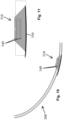
- Fig. 3A shows that a cross-section of the intubation tube 100 at a location above the area 200 (and above the first inflatable member 110) is circular in shape.
- Fig. 3B shows that a cross-section of the intubation tube 100 at a location within the area 200 is generally triangular in shape.
- Fig. 3C shows that a cross-section of the intubation tube 100 at a location below the area 200 (and below the second inflatable member 120) is circular in shape.
- the generally triangular shape of the outer surface of the intubation tube 100 within the area 200 is configured to mate with the larynx anatomy and prevents rotation of the intubation tube 100, while also increasing the surface area of the intubation tube 100 that is contact with the larynx tissue. It will be understood that the generally triangular shape of the intubation tube 100 can be restricted to a front portion of the intubation tube as shown in Fig. 3D in that it is defined by an integral protrusion (extension) that has a triangular shape and extends radially outward from the circular shaped tube portion.
- the posterior aspect to the intubation tube is circular in shape similar to a conventional intubation tube as shown.
- the modification of the front portion allows for decreased left/right rotation, whilst not increasing the diameter of the posterior tube portion. As set forth below, this increased surface area allows for increased electrode-tissue contact.
- Figs. 2 , 3B , 3D and 4 show details concerning the electrode section 200.
- the intubation tube 100 has a generally triangular shaped cross-section in the area 200 (electrode section) that is defined by a first side surface (face) 230, an opposing second side surface (face) 232, a third side surface (face) 234, and an opposing fourth side surface (face) 236.
- a central, circular shaped bore is also formed in area 200.
- the first and second side surfaces 230, 232 can be planar surfaces that are angled with respect to one another, while the third and fourth side surfaces 234, 236 can be arcuate shaped.
- the third side surface 234 has an arcuate length that is less than the fourth side surface 236.
- the reference recording electrode 220 can be a single electrode located along the third side surface 234 and more particularly, can be vertically oriented such that it extends longitudinally along a length of the intubation tube 100 within the area 200.
- the reference recording electrode 220 can be centrally oriented within the third side surface 234.
- the active recording electrodes 210 there is a plurality of active recording electrodes 210.
- the plurality of active recording electrodes 210 can be oriented parallel to one another and in series along a longitudinal length of the intubation tube 100 within the area 200 as shown.
- the electrodes 210 illustrated and described herein are merely exemplary in nature and not limiting of the scope of the present invention.
- the active recording electrodes 210 are in the form of bi-lateral electrode arrays in that, as best shown in Fig.
- the active recording electrodes 210 can be formed of a first array 211 that is formed along the first side surface 230 and a second array 213 that is formed along the opposing second side surface 232.
- Each of the first and second arrays 211, 213 is defined by parallel spaced electrode bands disposed along the outer surface of the intubation tube 100 and electrically connected to one another, as shown in Fig. 4 .
- each electrode band is operatively coupled to an electrical lead so as to electrically connect the electrode bands and permits a signal indicative of an LAR response to be delivered to a signal receiver (signal processor/recorder) that can record and/or analyze the signal as described below.
- signal receiver signal processor/recorder
- each of the first and second electrode arrays 211, 213 is configured to both provide an electrical stimulus (and thus acts as an active stimulation electrode) and also record signals, in this case, the contralateral R1 (cR1) and R2 (cR2) responses of the LAR (and thus act as an active recording electrode).
- the electrode arrays 211, 213 thus are configured to provide electrical stimuli to adjacent tissue by receiving electrical signal from a signal generator, which is described below, can be the same machine that records.
- the LAR was elicited by electrical stimulation of the laryngeal mucosa on the side contralateral to the operative field using the right or left surface electrodes (i.e., the first and second electrode arrays 211, 213) attached to the endotracheal tube 100 within area 200.
- the first and second electrode arrays 211, 213 can be disposed entirely along the faces 230, 232 that define the triangular shaped protrusion that extends radially outward from the circular shaped posterior portion of the intubation tube.
- the reference electrode 220 can also be positioned entirely within this triangular shaped portion as well.
- the placement of the bi-lateral electrode arrays 211, 213 between the first and second inflatable members (cuffs) 110, 120 also improves the signal to noise ratio.
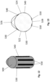
- the second inflatable member 120 includes one or more stimulation electrodes 300 that are disposed along an outer surface of the second inflatable member 120. See Figs. 5 and 6 . As shown, each stimulation electrode 300 extends about the outer surface (circumference) of the second inflatable member 120. The one or more stimulation electrodes 300 can be arranged in a latitudinal direction along the second inflatable member 120.
- a single stimulation electrode 300 disposed along the second inflatable member 120.
- a single stimulation electrode 300 is configured such that it can provide electrical stimulation of the laryngeal mucosa on the side contralateral to the operative field and thus, has coverage over both the left vocal fold and the right vocal fold.
- the optional second inflatable member 120, with the at least one stimulation electrode 300 is used, the at least one stimulation electrode 300 then becomes the stimulating electrode of the system and the first and second electrode arrays 211, 213 become the recording electrodes.
- One advantage of this type of arrangement is that it allows left and right sides to be recorded simultaneously, something not possible with the only currently available continuous monitoring technique which requires a vagus nerve electrode to be placed on the ipsilateral side to operation field prior to being able to record continuously.
- the active electrodes in area 200 namely, the first and second electrode arrays 211, 213 serve only as recording electrodes, thereby providing bi-lateral recording coverage.
- the second inflatable member 120 has a bi-lateral electrode configuration in that there is one stimulation electrode 300 disposed along one side of the second inflatable member 120 and another stimulation electrode 300 is disposed along the other side of the second inflatable member 120.
- Each stimulation electrode 300 can be oriented in a latitudinal direction along the second inflatable member 120; however, other orientations are equally possible.
- the positions of the stimulation electrodes 300 are such that one stimulation electrode 300 is for placement into direct contact with the left vocal fold and the other stimulation electrode 300 is for placement into direct contact with the right vocal fold.
- the second inflatable member 120 is present along with the first inflatable member 110; however, the second inflatable member 120 is free of any stimulation electrodes and thus, serves only as an anchoring balloon to prevent proximal and distal movement of the intubation tube 100.
- the stimulation electrode is thus one of the active electrodes 210 (e.g., first and second electrode arrays 211, 213) that is located within area 200 of the intubation tube 100 and the recording electrode is the other of the active electrodes 210.
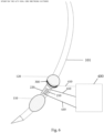
- each of the electrodes associated with the intubation tube 100 is electrically connected to a machine 400 that is configured to both generate stimuli and record responses to the applied stimuli (e.g., electric signals).
- the electrical connection between the individual electrodes and the machine 400 is by conventional means, such as wires or other type of connectors 410.
- the machine 400 can thus be a signal generator/receiver that is suitable for the present application in that it is configured to both generate electrical stimuli (electrical signals) and record electrical signals.
- One exemplary machine 400 is an Axon Sentinel 4 EP Analyzer machine (Axon Systems Inc.; Hauppauge, NY, USA) that comprises a multi-channel device that monitors and detects electrical signals (e.g., evoked potential monitoring) and is further configured to emit electrical signals (stimulation signals). Signals received by the machine 400 can be amplified, filtered and then stored on a computer device, such as a desk-top or laptop, or can be stored in the cloud (network). As described below, the machine 400 is configured such that the electrical stimuli can be directed to one or more electrodes and the character of the electrical stimuli can be controlled by the user, e.g., the frequency, duration, etc., of the electrical stimuli can be selected and controlled.
- Table 1 shows demographics, diagnosis and type of surgery for each patient.
- the anesthetic regimen consisted of total intravenous anesthesia (TIVA) using propofol and remifentanil in standard weight based doses.
- a Nerve Integrity Monitor TriVantage endotracheal tube (NIM TriVantage TM , Medtronics Xomed Inc.; Jacksonville, FL, USA) containing bilaterally imbedded conductive silver ink surface electrodes (See, Figs. 1A-1C ). These electrodes come into direct contact with the right and left vocal folds ( Figs. 1A and 1B ). It will be appreciated that both the intubation tube construction and the electrode construction and placement in Figs. 1A and 1B is different than the embodiment shown in Figs. 2-6 . More specifically, Figs.
- FIGS. 1A and 1B depict an intubation tube 10 having a first inflatable member (balloon cuff) 20, a first pair of electrodes 30 on one side (e.g., left) of the tube 10, and a second pair of electrodes 40 on the other side (e.g., right) of the tube 10.
- first inflatable member balloon cuff
- first pair of electrodes 30 on one side (e.g., left) of the tube 10
- second pair of electrodes 40 on the other side (e.g., right) of the tube 10.
- Axon Sentinel 4 EP Analyzer machine was utilized (Axon Systems Inc.; Hauppauge, NY, USA). This type of device is a multi-channel device that monitors and detects electrical signals (evoked potential monitoring). Other suitable machines can equally be used.
- the LAR was elicited by electrical stimulation of the laryngeal mucosa on the side contralateral to the operative field using the right or left surface electrodes attached to the endotracheal tube.
- the intubation tube 10 shown in Figs. 1A and 1B was operatively connected to a machine (e.g., the Axon Sentinel 4 EP Analyzer machine) that is configured not only to record but also to generate and deliver stimuli to certain select electrodes.
- a machine e.g., the Axon Sentinel 4 EP Analyzer machine
- the electrode(s) on one side of the tube can be selected as being a stimulating electrode(s) and the device to which the electrode(s) is electrically connected thus supplies electrical stimuli to this electrode.
- the electrode(s) on the other side of the tube would thus be selected and serve as the recording electrode(s). This is in direct contrast to the conventional use of the illustrated intubation tube in which both the left and right electrodes act only as recording electrodes.
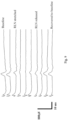
- the cR1 and cR2 responses were defined as the short and long-latency responses, respectively, elicited in the contralateral vocal fold muscles relative to the stimulating side ( Fig. 1C ).
- Signals were amplified (4000), filtered (bandwidth 1.5-1000 Hz), and stored on the computer for off-line analysis.
- the intensity of current required to elicit the LAR varied between 2mA (0.1ms duration) to 4mA (1ms duration) and the intensity required to elicit the reflex for each patient was adjusted throughout the surgery to obtain reliable cR1 responses.
- Reversible changes in the LAR manifesting as increased latency and decreased amplitude of response from baseline were noted to occur during every surgery. In every surgery, the timing of these changes correlated temporally with surgical maneuvers that would have put stretch or compression directly on the RLN. During times when the RLN was out of the operative field, the LAR remained constant in amplitude and latency. None of the patients had intraoperative total reflex loss and, postoperatively, no patient had objective vocal cord paralysis. No intra-operative or post-operative complications relating to the stimulation or recording of the LAR were noted for any patient.
- the LAR is a brainstem reflex that protects the larynx from aspiration.
- Afferent and efferent limbs of the LAR are mediated by two distinctive branches of the vagus nerve, the SLN and the RLN.
- the afferent limb carries information from sensory receptors in the supraglottic and glottic mucosa (likely mechanoreceptors and chemoreceptors) through the iSLN.
- the inferior glottis and subglottic regions of the larynx receive sensory fibers from the RLN which may also contribute to the reflex during mucosal stimulation with surface based endotracheal tube electrodes.
- the efferent limb of the LAR is mediated by motor fibers of the RLN.
- ipsilateral R1 An early ipsilateral response (relative to the stimulus) called ipsilateral R1 (iR1) has been extensively recorded in anesthetized cats, dogs, pigs and humans.
- cR1 contralateral R1 response
- a longer latency R2 response that produces bilateral vocal cord adduction have been recorded in awake humans. Latency of iR1 in awake and anesthetized humans is typically between 13-18 ms (milliseconds).
- the latency of the human cR1 response is approximately 4ms longer than the latency of the iR1 response, and proposed different models of brainstem circuitry for iR1 and cR1 responses.
- the iR1 was proposed to project from the iSLN to motor neurons of the ipsilateral nucleus ambiguus via the ipsilateral nucleus of the tractus solitarius.
- the cR1 would project from the ipsilateral nucleus of the tractus solitarius to the contralateral nucleus ambiguous via 2-3 additional interneuron synapses within the reticular formation, thus giving the contralateral adduction of the reflex.
- cranial nerve mapping of the vagus nerve and cortico-bulbar motor evoked potentials Cranial nerve mapping is one of the most utilized methodologies but depends on surgeon participation and cannot be used continuously.
- Cortico-bulbar MEPs can continuously assess the integrity of nerves, nuclei and central pathways if used frequently however they provoke movement due to transcranial electrical stimulation that interrupts the surgery and thus the frequency of application is limited.
- the LAR is simple to perform and does not evoke movement or cause any disruption to the surgical procedure.
- Positioning of the electrodes on the endotracheal tube is of crucial importance to the success of this reflex.
- the electrodes must be positioned so that they oppose the glottic mucosa for both stimulation and recording purposes.
- tube position should be checked. The tube position is optimally checked by using a laryngoscope however it can also be checked without using laryngoscopy by moving the tube in a rotational or proximal-distaldirection and testing the reflex in each new tube position. Finally, if none of the above maneuvers recovers the reflex to baseline levels, true reflex changes due to impending nerve injury can be suspected.
- Loss of the LAR is a warning criteria for the surgeon to stop the surgery and explore the surgical field to confirm nerve injury.
- Table 1 Patient Gender Age Diagnosis Surgery 1 F 35 Left thyroid goiter Left thyroidectomy 2 M 50 Thyroid carcinoma metastatic Total thyroidectomy 3 F 78 Spondylolisthesis C4 and C5.
- intra-operative application of the LAR using endotracheal tube surface based electrodes and contralateral R1 responses is a viable method of monitoring recurrent laryngeal and vagus nerve integrity during surgery.
- the results from the above study indicate that the LAR was reliably elicited in 100% of patients for the duration of each surgical procedure.
- Mean onset latency of cR1 response was 22.4 +/- 2.5 ms (right) and 22.2+/-2.4 ms (left).
- cR2 responses were noted in 10 patients (66.7%). No peri-operative complications or adverse outcomes were observed.
- the LAR is a novel neuro-monitoring technique for the vagus nerve and in particular, represents a novel method for intraoperatively monitoring laryngeal and vagus nerves.
- the LAR monitors the entire vagus nerve reflex arc and is thus applicable to all surgeries where vagal nerve integrity may be compromised.
- Advantages over current monitoring techniques including simplicity, ability to continuously monitor neural function without placement of additional neural probes and ability to assess integrity of both sensory and motor pathways.
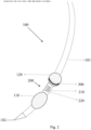
- Figs. 10-14 illustrate an alternative intubation tube 500 according to another embodiment.
- the intubation tube 500 is similar to intubation tube 100 and is in the form of an elongated structure (tubular body) that includes a proximal end (not shown) that is located and positioned outside of the patient and a distal end for insertion into the patient.
- the intubation tube 500 can be formed in any number of different sizes and can be formed to have any number of different shapes; however, a circular shape is most common.
- the intubation tube 500 can have a variable cross-sectional shape in that one or more sections of the tube can have one shape (e.g., circular), while one or more other sections can have another, different shape (e.g., triangular as described below).
- one or more sections of the tube can have one shape (e.g., circular), while one or more other sections can have another, different shape (e.g., triangular as described below).
- the intubation tube 500 includes a first inflatable member 110 (see, Fig. 2 ) and optionally includes a second inflatable member 120 (see, Fig. 2 ) that is spaced proximal to the first inflatable member 110.
- first and second inflatable members 110 120 are not shown in Fig. 10 .
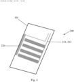
- an electrode section (electrode area) 510 shown in Figs. 10-12 is positioned between the first and second inflatable members along the elongated body of the intubation tube 500.
- the electrode section or area 510 which can be located between the first inflatable and second inflatable members 110, 120 ( Fig. 2 ) of the intubation tube 500 can be in the form of an electrode section. More specifically, the electrode area 510 is configured as a multi-functional electrode section. In particular, unlike the previous embodiment in which the stimulation electrodes were placed on the second cuff (second inflatable member 120), the electrode area 510 includes both recording and stimulation electrodes as described in detail below.
- the electrode area 510 is generally triangularly shaped like electrode section 200 of the previous embodiment.
- the intubation tube has a first portion 520 that is generally circular in shape and an adjacent second portion 530 that protrudes radially outward from the first portion 520.
- Figs. 10-12 illustrate exemplary constructions for the intubation tube 100.
- a cross-section of the intubation tube 500 at a location above the area 510 (and above the first inflatable member 110 ( Fig. 1 )) is circular in shape.
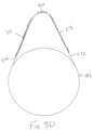
- Fig. 13 shows that a cross-section of the intubation tube 500 at a location within the area 510 is generally triangular in shape.
- a cross-section of the intubation tube 500 at a location below the area 510 (and below the second inflatable member 120 ( Fig. 1 )) is circular in shape.
- the generally triangular shape of the outer surface of the intubation tube 500 within the area 510 is configured to mate with the larynx anatomy and prevents rotation of the intubation tube 500, while also increasing the surface area of the intubation tube 500 that is contact with the larynx tissue. It will be understood that the generally triangular shape of the intubation tube 500 can be restricted to a front portion of the intubation tube as shown in Figs. 12 and 13 in that it is defined by an integral protrusion (extension) that has a triangular shape and extends radially outward from the circular shaped tube portion.
- the posterior aspect to the intubation tube is circular in shape similar to a conventional intubation tube as shown.
- the modification of the front portion allows for decreased left/right rotation, whilst not increasing the diameter of the posterior tube portion. As set forth below, this increased surface area allows for increased electrode-tissue contact.
- the intubation tube 500 has a generally triangular shaped cross-section in the area 510 (electrode section) that can generally be thought of as including a first side surface (face) 522, an opposing second side surface (face) 524, a third side surface (face) 526 which is an anterior portion, and an opposing fourth side surface (face) 528 which is a posterior portion.
- a central, circular shaped bore is also formed in area 510.
- the first and second side surfaces 522, 524 can be slightly curved or planar surfaces that are angled with respect to one another, while the third and fourth side surfaces 526, 528 can be arcuate shaped.
- the third side surface 526 has an arcuate length that is less than the fourth side surface 528.
- the electrode area 510 includes a plurality of recording electrodes and in particular, includes at least one first electrode 530 in the form of an active recording electrode and the at least one second electrode 540 in the form of a reference recording electrode.
- the electrodes 530, 540 are described in more detail below.
- the electrode area 510 preferably includes bi-lateral active electrodes that are configured to both provide stimulation and record tissue response depending upon the precise application (e.g., the location of the operative site) and therefore, there are at least two recording electrodes, with at least one electrode being on one side of the intubation tube 500 within the area 510 and at least one electrode being on the other side of the intubation tube 500 within the area 510.
- one recording electrode 530 is located on the first side 522, while one recording electrode 540 is located on the opposite side 524. As shown, there are preferably a pair of recording electrode 530 on the first side 522 and a pair of electrodes 540 on the second side 524.
- the electrodes 530 can run longitudinally along the intubation tube 500 and are parallel to one another and similarly, the electrodes 540 can run longitudinally along the intubation tube 500 and are parallel to one another.
- one electrode 530 is proximate the anterior (generally triangular shaped) protrusion, while the other electrode 530 is located along the circular shaped body closer to the posterior side.
- the pair of electrodes 540 in that one can be located proximate the anterior protrusion with the other being closer to the posterior side.
- Fig. 11 shows a side (lateral) view of the electrode area 510 and it can be seen that from the side view, one pair of recording electrodes (in this case electrodes 540) can be seen (from the other side view, the other pair of electrodes 530 can be seen).
- one pair of recording electrodes in this case electrodes 540
- the other pair of electrodes 530 can be seen.
- the electrode area 510 includes one or more stimulation electrodes 550 that are disposed along an outer surface of the intubation tube 500 within the electrode area 510 as shown in the figures.
- the illustrated embodiment includes a pair of stimulation electrodes 550 that are located along the fourth side 528 (posterior side) of the intubation tube 500.
- the stimulation electrodes 550 can run longitudinally and are spaced apart (in a parallel manner).
- the lengths of the recording electrodes 530, 540 and the stimulation electrodes 550 are shown as generally be equal and the widths are shown as generally being equal, it will be appreciated that the lengths and/or widths can be different.
- the stimulating electrodes 550 become the stimulating electrodes of the system and the first and second electrode arrays 230, 240 become the recording electrodes.
- One advantage of this type of arrangement is that it allows left and right sides to be recorded simultaneously, something not possible with the only currently available continuous monitoring technique which requires a vagus nerve electrode to be placed on the ipsilateral side to operation field prior to being able to record continuously.
- the first and second electrode arrays 530, 540 serve only as recording electrodes, thereby providing bi-lateral recording coverage.
- the electrode area 510 also has a bi-lateral electrode configuration in that there is one stimulation electrode 550 disposed along one side of the electrode area 510 and another stimulation electrode 550 is disposed along the other side of the electrode area 510.
- the design of the intubation tube 500 improves IIONM and CIONM by improving signal specificity, increasing tissue contact with electrodes, and preventing rotation and proximal/distal movement of the intubation tube 500.
- the optional second inflatable member (balloon or cuff) 120 ( Fig. 2 ) can be positioned along the intubation tube 500 at a location that will be distal to the larynx for preventing proximal/distal movement.
- the triangular outer surface of the intubation tube 500 between cuffs (first and second inflatable members of Fig. 1 ) mates with the larynx anatomy and therefore, prevents rotation and increases electrode-tissue contact.
- bi-lateral electrode arrays e.g., the bi-lateral recording electrodes 530, 540 and bi-lateral stimulation electrodes 550
- the cuffs first and second inflatable members of Fig. 1
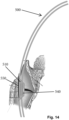
- the stimulation electrodes 550 can, in the illustrated embodiment, be thought of as being posterior arytenoid rim stimulation electrodes.
- the illustrated intubation tube 500 allows for bilateral reflex recording.
- the illustrated intubation tube 500 thus includes a total of 6 electrodes (3 pairs) with 4 electrodes (2 pairs) being recording electrodes and 2 electrodes (1 pair) being stimulation electrodes.
- the presence of strong bilateral LAR responses upon stimulation posteriorly in 100% patients implies that the stimulating electrodes for the LAR tube in a preferred embodiment would be placed posteriorly, abutting the medial surface of each arytenoid cartilage.
- the recording electrodes are best placed more anteriorly, on the lateral tube surface, in order to record responses in the lateral cricoarytenoid muscles. This topography of responses with regards to the human larynx has not been previously investigated and no data except the data generated by the present Applicant exists.
- Fig. 15 is a cross-sectional view of an exemplary electrode section of an intubation tube in accordance with the present invention.
- Fig. 15 lists exemplary dimensions and exemplary placements for the different types of electrodes that are part of the intubation tube.
- each recording electrode can have a width of about 3 mm and a length of about 30 mm.
- the inter-electrode gap between adjacent recording electrodes is about 7 mm.
- Each stimulation electrode can have a width of about 2 mm and a length of about 50 mm.
- the inter-electrode gap between adjacent recording electrodes can be about 4 mm.
- the recording electrodes in Fig. 15 can correspond to the recording electrodes 530, 540 in Fig. 13 and the stimulating electrodes can correspond to the stimulating electrodes 550 in Fig. 13 .
- Figs. 10, 11 and 14 show a vocal cord level marker (cross symbol) that assists in the positioning of the device (intubation tube) relative to the vocal cord.
- the marker can be a line (indicia) formed on the tube for visualization.
- Anesthesia was induced with Propofol and succinylcholine and maintained using total intravenous anesthesia (TIVA) with Propofol and opioids (remifentanil). Inhalational and topical laryngeal anesthetic agents were avoided. Intubation was performed with a Nerve Integrity Monitor TriVantage endotracheal tube (NIM TriVantageTM, Medtronics Xomed Inc.; Jacksonville, FL, USA). The patient's neck was extended and ET position rechecked and adjusted using video laryngoscopy (GlideScope, Verathon Inc. Seattle, WA, USA) to ensure electrodes were in direct contact with right and left laryngeal mucosa. The tube was fixed with standard tape and, in 75% of patients, an oral endotracheal tube fastener (Anchor-FastTM, Libertyville, IL, USA).
- Nerve stimulation was performed with a monopolar handheld stimulating probe (Medtronic Xomed, Jacksonville, FL, USA) with a subdermal sternal reference needle. Single stimuli of 0.1ms duration with maximum intensity 2 mA at repetition rate 4Hz were applied. Responses were stimulated and recorded on a NIM-Response 3.0 machine (Medtronic Xomed, Inc., Jacksonville, Florida, U.S.A.). Loss of signal (LOS) was defined as an EMG amplitude response below 100 ⁇ V with an absent posterior cricoarytenoid muscular twitch response on laryngeal palpation during vagal and RLN stimulation. LOS was classified into Type 1 (segmental) and Type 2 (diffuse) injury.
- LOS Loss of signal
- the LAR was elicited by electrical stimulation of laryngeal mucosa on the side contralateral to the operative field using ET electrodes.
- a single-stimulus (0.1-1 ms duration) at intensity ⁇ 15 mA using the minimal current necessary for supramaximal stimulation was applied.
- Vocal fold adduction was recorded by ET electrodes contralateral to the stimulating side.
- Responses were stimulated and recorded on an Axon Sentinel 4 EP Analyzer machine (Axon Systems Inc.; Hauppauge, NY, U.S.A.) or Medtronic Eclipse ® system (Medtronic Xomed, Inc., Jacksonville, FL, USA). Signals were filtered (bandwidth 1.5-1,000 Hz) and stored for offline analysis.
- Table 3 Patient, disease and surgical demographics Variables Values Mean age in years (StDev) 50.8 (15.5) Gender Male 18 Female 82 Pre-operative surgical indications Goiter with compressive symptoms 38 Grave's disease 4 Bethesda 3 or 4 with high-risk molecular markers 39 Carcinoma 10 Hyperparathyroidism 9 Surgery type Left thyroid lobectomy 31 Right thyroid lobectomy 33 Total thyroidectomy 27 Parathyroidectomy 9 Pathology Benign 53 Hashimoto thyroiditis / Grave's disease 29 Malignant 18 Number of nerves at risk 134 Mean LAR-CIONM duration (minutes) 105 Table 1: Patient, disease and surgical demographics
- Table 4 presents nerve injury data grouped by pre-operative nerve function.
- Patients 1 and 2 had normal pre-operative laryngeal examinations with post-operative hypomobility of the ipsilateral vocal fold to 50% of the contralateral fold. Both patients had palpable posterior cricoarytenoid muscle twitches during intraoperative vagal nerve stimulation.
- Patient 1 had a posteriorly located right 2.2cm papillary thyroid carcinoma with extrathyroidal extension. A decrement in LAR amplitude occurred during sharp dissection of the nerve off the tumor (77.6% decrement).
- Normal laryngeal function returned at 5-weeks post-operatively.
- Patient 2 had thyromegaly with a prominent tubercle of Zuckerkandl and exhibited a 67.4% LAR amplitude decrement. She had left vocal fold hypomobility at day 3 that returned to normal by day 10 postoperatively.
- Patients 3, 4 and 5 had normal pre-operative laryngeal examinations with post-operative transient vocal fold paralysis (2.2% unanticipated nerve paralysis rate). All recovered baseline laryngeal function by 6 weeks postoperatively. Patients 3 and 4 exhibited Type 2 loss of CMAP signal (LOS) presumably due to traction, and patient 5 was a Type 1 nerve injury due to heat damage from adjacent cautery. All patients had > 60% amplitude decrement between the opening and closing LAR values (Table 4) and exhibited significant decreases on their VHI-10 questionnaires (mean pre-operative 0.67, mean 1-week post-operative 10.3) that returned to baseline by 6 weeks postoperatively.
- LOS Type 2 loss of CMAP signal
- Patients 6 and 7 had pre-operative vocal fold paresis with post-operative vocal fold paralysis. Both patients had posteriorly located thyroid carcinomas with features of extrathyroidal extension (ETE).
- ETE extrathyroidal extension
- the nerve was cut off the tumor with a Type 1 LOS at this site and a > 60% amplitude decrement between the opening and closing LAR values.
- Final pathology showed microscopic ETE at the site of dissection. Although the vocal fold retains good tone in a medialized position, cord mobility has not returned 10 months post-operatively.
- Pre- and post-operative VHI-10 scores are comparable at 6.0.
- Patient 7 had complete encasement of the RLN by tumor and the nerve was sacrificed.
- the LAR represents a novel method to continuously monitor the vagus nerve during surgical procedures.
- the only commercially available vagal CIONM technique requires potentially harmful manipulation of the vagus nerve for electrode placement. Electrode dislocation intra-operatively necessitates repeat nerve manipulation and disrupts the core analysis of the Automatic Periodic Stimulation (APS ® ) system for detecting significant CMAP decrements.
- APS ® Automatic Periodic Stimulation
- LAR-CIONM uses non-invasive ET electrodes alone to both stimulate and record vagal responses. This methodological advantage makes the LAR-CIONM particularly attractive for minimally invasive neck surgeries and neurosurgical procedures.
- LAR-CIONM is extremely sensitive to changes in nerve excitability induced by RLN stretch or compression, necessitating frequent relaxation of tissues during surgical procedures to assess for reversibility of observed LAR-CIONM amplitude decrements.
- LAR-CIONM can thus provide very early warning of potential nerve injury and may prove more effective than CMAP responses in preventing type 2 LOS injuries because traction injuries are reversible when prompt corrective measures are applied.
- Increased latency of LAR responses did not predict nerve injury in this series. This suggests that the concept of the ⁇ combined event' to predict postoperative nerve paralysis for CMAP responses may not apply to the LAR.
- the devices and method disclosed herein can be adapted to monitor the LAR using the ipsilateral iR1 component of the reflex for both stimulation and recording purposes.
- Electrodes ipsilateral to the surgical field (and also ipsilateral to the stimulation side) attached to the endotracheal tube can be used to record the ipsilateral R1 (iR1) and R2 (iR2) responses of the LAR.
- the iR1 and iR2 responses were defined as the short and long-latency responses, respectively, elicited in the ipsilateral vocal fold muscles relative to the stimulating side.
- the device shown in Fig. 13 can be adapted and configured such that posterior pair of electrodes 550 act as the stimulating electrodes and due to their posterior position, these electrodes 550 will elicit an ipsilateral response that is recoded by an ipsilateral recording electrode, such as electrode(s) 530 and/or 540.
- the device of Fig. 13 can be modified such that that the stimulating electrodes 550 can be eliminated or rendered inactive and for each of the pairs of electrodes 530, 540, the posterior electrode of the pair acts as a stimulating electrode, while the anterior electrode of the pair acts as the recording electrode.
- the recording and stimulating electrodes are located on the same side of the tube. Ipsilateral iR1 recording can be achieved by separation of the stimulation electrode(s) from the recording electrode(s) with the stimulation electrode(s) being placed posterior to the recording electrode(s). It will be understood that these teachings can also be implemented in tubes having other constructions such as the other ones described herein.
Claims (12)
- Système comprenant :
un tube endotrachéen pour suivre intraopératoirement les nerfs laryngéens et vagal en obtenant une réponse d'adducteur laryngéen (Laryngeal Adductor Response, LAR) chez un patient qui est sous anesthésie générale, à savoir un type qui préserve la LAR et en suivant les réponses contre-latérales de la LAR qui sont détectées après l'application d'une stimulation électrique comprenant :un corps de tube intratrachéen (101) ayant un premier élément gonflable (110) et une zone d'électrode (200) qui comprend une pluralité d'électrodes à base de surface, les électrodes à base de surface comprenant une première électrode à base de surface (210) qui est située le long d'un premier côté du tube endotrachéen et une seconde électrode à base de surface (220) qui est située le long d'un second côté du tube endotrachéen, chacune des première et seconde électrodes à base de surface étant configurée pour émettre une stimulation électrique et enregistrer les réponse de la LAR ; etun signal générateur/receveur qui est couplé électriquement aux électrodes à base de surface de manière à délivrer une stimulation électrique à une choisie des première et secondes électrodes à base de surface et enregistrer les réponses de la LAR de l'autre des première et seconde électrodes à base de surface. - Système selon la revendication 1, dans lequel les électrodes à base de surface sont configurées pour le positionnement en contact direct avec les replis vocaux gauche et droit.
- Système selon la revendication 1, dans lequel la première électrode à base de surface comprend un premier réseau (211) d'électrodes et la seconde électrode à base de surface comprend un second réseau (213) d'électrodes.
- Système selon la revendication 3, où le premier réseau (211) d'électrodes comprend une pluralité d'électrodes espacées en parallèle qui sont interconnectées électriquement et le second réseau (213) d'électrodes comprend une pluralité d'électrodes espacées en parallèle qui sont interconnectées électriquement.
- Système selon la revendication 1, dans lequel la zone d'électrode du tube endotrachéen a une section transversale en forme généralement triangulaire configurée pour s'apparier avec une anatomie de larynx du patient.
- Système selon la revendication 5, dans lequel la section transversale généralement de forme triangulaire est définie par une première paroi latérale et une seconde paroi latérale opposée, la première paroi latérale comprenant la première électrode à base de surface qui comprend un premier réseau (211) d'électrodes à base de surface et la seconde paroi latérale comprenant la seconde électrode à base de surface qui comprend un second réseau (213) d'électrodes à base de surface.
- Système selon la revendication 5, comprenant en outre un second élément gonflable (120) pour un placement distal à un larynx du patient et les électrodes à base de surface du tube endotrachéen étant disposées entre les premier et second éléments gonflables (110, 120).
- Système selon la revendication 7, dans lequel chacun des premier et second éléments gonflables comprend une coiffe ou un ballon gonflable.
- Système selon la revendication 7, dans lequel les électrodes à base de surface disposées entre les premier et second éléments gonflables comprennent des réseaux d'électrodes bi-latéraux.
- Système selon la revendication 7, dans lequel le second élément gonflable comprend au moins une électrode de stimulation pour fournir la stimulation électrique et les électrodes à base de surface disposées entre le premier et le second éléments gonflables comprennent des électrodes qui enregistrent seulement les réponses de la LAR.
- Système selon la revendication 10, dans lequel l'au moins une électrode de stimulation permet un neurosuivi interopératoire continu (Continous Interoperative Neurominitoring, CIONM) sans utilisation d'une électrode vagale.
- Système selon la revendication 1, dans lequel les électrodes à base de surface sont connectées électriquement au générateur/receveur de signal au moyen de fils.
Priority Applications (1)
| Application Number | Priority Date | Filing Date | Title |
|---|---|---|---|
| EP24157065.4A EP4342379A2 (fr) | 2016-12-23 | 2017-12-22 | Système d'évaluation de l'intégrité du nerf laryngé et du nerf vague chez des patients sous anesthésie générale |
Applications Claiming Priority (3)
| Application Number | Priority Date | Filing Date | Title |
|---|---|---|---|
| US201662438862P | 2016-12-23 | 2016-12-23 | |
| US201762552755P | 2017-08-31 | 2017-08-31 | |
| PCT/US2017/068333 WO2018119454A1 (fr) | 2016-12-23 | 2017-12-22 | Procédé et système d'évaluation de l'intégrité du nerf laryngé et du nerf vague chez des patients sous anesthésie générale |
Related Child Applications (1)
| Application Number | Title | Priority Date | Filing Date |
|---|---|---|---|
| EP24157065.4A Division EP4342379A2 (fr) | 2016-12-23 | 2017-12-22 | Système d'évaluation de l'intégrité du nerf laryngé et du nerf vague chez des patients sous anesthésie générale |
Publications (3)
| Publication Number | Publication Date |
|---|---|
| EP3558451A1 EP3558451A1 (fr) | 2019-10-30 |
| EP3558451A4 EP3558451A4 (fr) | 2020-09-02 |
| EP3558451B1 true EP3558451B1 (fr) | 2024-02-14 |
Family
ID=62627938
Family Applications (2)
| Application Number | Title | Priority Date | Filing Date |
|---|---|---|---|
| EP17884784.4A Active EP3558451B1 (fr) | 2016-12-23 | 2017-12-22 | Système d'évaluation de l'intégrité du nerf laryngé et du nerf vague chez des patients sous anesthésie générale |
| EP24157065.4A Pending EP4342379A2 (fr) | 2016-12-23 | 2017-12-22 | Système d'évaluation de l'intégrité du nerf laryngé et du nerf vague chez des patients sous anesthésie générale |
Family Applications After (1)
| Application Number | Title | Priority Date | Filing Date |
|---|---|---|---|
| EP24157065.4A Pending EP4342379A2 (fr) | 2016-12-23 | 2017-12-22 | Système d'évaluation de l'intégrité du nerf laryngé et du nerf vague chez des patients sous anesthésie générale |
Country Status (10)
| Country | Link |
|---|---|
| US (1) | US11400279B2 (fr) |
| EP (2) | EP3558451B1 (fr) |
| JP (1) | JP7326674B2 (fr) |
| KR (1) | KR102491751B1 (fr) |
| CN (1) | CN110392592B (fr) |
| AU (1) | AU2017382441B2 (fr) |
| BR (1) | BR112019012998A2 (fr) |
| CA (1) | CA3046988C (fr) |
| RU (1) | RU2769849C2 (fr) |
| WO (1) | WO2018119454A1 (fr) |
Families Citing this family (3)
| Publication number | Priority date | Publication date | Assignee | Title |
|---|---|---|---|---|
| AU2017382441B2 (en) | 2016-12-23 | 2023-07-27 | Icahn School Of Medicine At Mount Sinai | Method and system for assessing laryngeal and vagus nerve integrity in patients under general anesthesia |
| CA3072609A1 (fr) * | 2017-08-22 | 2019-02-28 | Medtronic Xomed, Inc. | Systeme et procede pour evoquer un reflexe pour surveiller les nerfs du larynx |
| GB202109874D0 (en) | 2021-07-08 | 2021-08-25 | Technomed Eng Bv | Nerve monitoring apparatus |
Family Cites Families (31)
| Publication number | Priority date | Publication date | Assignee | Title |
|---|---|---|---|---|
| US4155353A (en) * | 1976-11-18 | 1979-05-22 | Davis William E | Electrode and method for laryngeal electromyography |
| US4907602A (en) * | 1985-10-18 | 1990-03-13 | The Mount Sinai School Of Medicine Of The City Of New York | Device for controlling the glottic opening |
| US5016647A (en) | 1985-10-18 | 1991-05-21 | Mount Sinai School Of Medicine Of The City University Of New York | Method for controlling the glottic opening |
| ATE55697T1 (de) * | 1986-05-12 | 1990-09-15 | Univ California | Elektronisches system zur nervenstimulation von beckenorganen. |
| US5024228A (en) | 1989-11-29 | 1991-06-18 | Goldstone Andrew C | Electrode endotracheal tube |
| US5125406A (en) * | 1989-11-29 | 1992-06-30 | Eet Limited Partnership (Del) | Electrode endotracheal tube |
| JP3182230B2 (ja) | 1992-10-14 | 2001-07-03 | 三洋電機株式会社 | 太陽光発電装置 |
| GB9422224D0 (en) * | 1994-11-03 | 1994-12-21 | Brain Archibald Ian Jeremy | A laryngeal mask airway device modified to detect and/or stimulate mescle or nerve activity |
| US6213960B1 (en) * | 1998-06-19 | 2001-04-10 | Revivant Corporation | Chest compression device with electro-stimulation |
| WO2003000338A2 (fr) * | 2001-06-21 | 2003-01-03 | Vanderbilt University | Technique favorisant la re-innervation de tissu denerve |
| EP1809369A4 (fr) * | 2004-10-18 | 2010-06-09 | Univ Louisiana Tech Foundation | Dispositif medicaux pour la detection, la prevention et/ou le traitement de troubles neurologiques, et procedes associes |
| WO2006102591A2 (fr) | 2005-03-24 | 2006-09-28 | Vanderbilt University | Stimulateur larynge bilateral declenche par la respiration servant a restaurer une ventilation normale en cas de paralysie des cordes vocales |
| US20060254595A1 (en) * | 2005-05-13 | 2006-11-16 | Rea James L | Endotracheal positioning device |
| US8886280B2 (en) * | 2007-01-23 | 2014-11-11 | The Magstim Company Limited | Nerve monitoring device |
| EP2120693A4 (fr) | 2007-01-23 | 2011-04-27 | Jack M Kartush | Dispositif d'examen d'un nerf |
| WO2010091440A2 (fr) * | 2009-01-20 | 2010-08-12 | Samir Bhatt | Dispositifs de gestion des voies aériennes, conduits endoscopiques, trousses chirurgicales et leurs procédés d'utilisation |
| US9254383B2 (en) * | 2009-03-20 | 2016-02-09 | ElectroCore, LLC | Devices and methods for monitoring non-invasive vagus nerve stimulation |
| US20110093032A1 (en) * | 2009-08-05 | 2011-04-21 | Ndi Medical, Llc | Systems and methods for maintaining airway patency |
| AU2010300373B2 (en) * | 2009-10-02 | 2014-04-24 | Medtronic-Xomed, Inc. | Endotracheal tube apparatus |
| US8983610B2 (en) * | 2009-11-18 | 2015-03-17 | Case Western Reserve University | Hybrid method for modulating upper airway function in a subject |
| US8423134B2 (en) * | 2010-04-29 | 2013-04-16 | Medtronic, Inc. | Therapy using perturbation and effect of physiological systems |
| WO2014105759A1 (fr) * | 2012-12-24 | 2014-07-03 | E-Motion Medical, Ltd. | Dispositifs et procédés de stimulation de tractus gastro-intestinal |
| US9345885B2 (en) * | 2011-12-07 | 2016-05-24 | Med-El Elektromedizinische Geraete Gmbh | Pacemaker for unilateral vocal cord autoparalysis |
| US9931079B2 (en) * | 2012-01-04 | 2018-04-03 | Medtronic Xomed, Inc. | Clamp for securing a terminal end of a wire to a surface electrode |
| EP2830703B1 (fr) * | 2012-03-29 | 2019-06-19 | MED-EL Elektromedizinische Geräte GmbH | Appareil pour le traitement de la dysphonie |
| US9060744B2 (en) * | 2012-11-29 | 2015-06-23 | Medtronic Xomed, Inc. | Endobronchial tube apparatus |
| US9913594B2 (en) * | 2013-03-14 | 2018-03-13 | Medtronic Xomed, Inc. | Compliant electrode for EMG endotracheal tube |
| US10542911B2 (en) | 2014-09-23 | 2020-01-28 | The Curators Of The University Of Missouri | System and method for laryngeal reflex examination |
| US10799152B2 (en) * | 2016-08-11 | 2020-10-13 | Medtronic Xomed, Inc. | System and method for motion detection and accounting |
| AU2017382441B2 (en) | 2016-12-23 | 2023-07-27 | Icahn School Of Medicine At Mount Sinai | Method and system for assessing laryngeal and vagus nerve integrity in patients under general anesthesia |
| US20190059812A1 (en) * | 2017-08-22 | 2019-02-28 | Medtronic Xomed, Inc. | System and method for evoking a reflex to monitor the nerves of the larynx |
-
2017
- 2017-12-22 AU AU2017382441A patent/AU2017382441B2/en active Active
- 2017-12-22 JP JP2019534298A patent/JP7326674B2/ja active Active
- 2017-12-22 BR BR112019012998A patent/BR112019012998A2/pt unknown
- 2017-12-22 WO PCT/US2017/068333 patent/WO2018119454A1/fr unknown
- 2017-12-22 KR KR1020197020646A patent/KR102491751B1/ko active IP Right Grant
- 2017-12-22 CA CA3046988A patent/CA3046988C/fr active Active
- 2017-12-22 EP EP17884784.4A patent/EP3558451B1/fr active Active
- 2017-12-22 US US16/472,720 patent/US11400279B2/en active Active
- 2017-12-22 RU RU2019123190A patent/RU2769849C2/ru active
- 2017-12-22 EP EP24157065.4A patent/EP4342379A2/fr active Pending
- 2017-12-22 CN CN201780087006.9A patent/CN110392592B/zh active Active
Also Published As
| Publication number | Publication date |
|---|---|
| CN110392592A (zh) | 2019-10-29 |
| AU2017382441A1 (en) | 2019-07-04 |
| AU2017382441B2 (en) | 2023-07-27 |
| EP4342379A2 (fr) | 2024-03-27 |
| CA3046988A1 (fr) | 2018-06-28 |
| JP7326674B2 (ja) | 2023-08-16 |
| US11400279B2 (en) | 2022-08-02 |
| RU2019123190A3 (fr) | 2021-04-26 |
| CN110392592B (zh) | 2023-04-21 |
| KR20190099241A (ko) | 2019-08-26 |
| RU2769849C2 (ru) | 2022-04-07 |
| EP3558451A4 (fr) | 2020-09-02 |
| EP3558451A1 (fr) | 2019-10-30 |
| US20200179676A1 (en) | 2020-06-11 |
| BR112019012998A2 (pt) | 2019-12-10 |
| KR102491751B1 (ko) | 2023-01-25 |
| JP2020513901A (ja) | 2020-05-21 |
| CA3046988C (fr) | 2024-03-12 |
| WO2018119454A1 (fr) | 2018-06-28 |
| RU2019123190A (ru) | 2021-01-25 |
Similar Documents
| Publication | Publication Date | Title |
|---|---|---|
| US8788036B2 (en) | Method for facilitating interface with laryngeal structures | |
| US11081222B2 (en) | Obstructive sleep apnea treatment screening methods | |
| US20200316377A1 (en) | Methods for prevention, moderation, and/or treatment of cognitive injury | |
| US11944810B2 (en) | Systems and methods for trans-esophageal sympathetic ganglion recruitment | |
| US20110093032A1 (en) | Systems and methods for maintaining airway patency | |
| JP2020518300A (ja) | 呼吸機能を可能にするための、脊髄ネットワークへのアクセス | |
| EP3558451B1 (fr) | Système d'évaluation de l'intégrité du nerf laryngé et du nerf vague chez des patients sous anesthésie générale | |
| US20220054825A1 (en) | Peripheral Nerve Electrode Array | |
| Téllez et al. | Unearthing a consistent bilateral R1 component of the laryngeal adductor reflex in awake humans | |
| Aygun et al. | Recent developments of intraoperative neuromonitoring in thyroidectomy | |
| Hadley et al. | Targeted transtracheal stimulation for vocal fold closure | |
| Murphy et al. | Chronically implanted epineural electrodes for repeated assessment of nerve conduction velocity and compound action potential amplitude in rodents | |
| Strain et al. | Electrodiagnostic evaluation of the nervous system | |
| Volk et al. | Electrophysiological Assessment | |
| BOOK | SREE CHITRA TIRUNAL INSTITUTE FOR MEDICAL SCIENCES &TECHNOLOGY (SCTIMST) |
Legal Events
| Date | Code | Title | Description |
|---|---|---|---|
| STAA | Information on the status of an ep patent application or granted ep patent |
Free format text: STATUS: THE INTERNATIONAL PUBLICATION HAS BEEN MADE |
|
| PUAI | Public reference made under article 153(3) epc to a published international application that has entered the european phase |
Free format text: ORIGINAL CODE: 0009012 |
|
| STAA | Information on the status of an ep patent application or granted ep patent |
Free format text: STATUS: REQUEST FOR EXAMINATION WAS MADE |
|
| 17P | Request for examination filed |
Effective date: 20190719 |
|
| AK | Designated contracting states |
Kind code of ref document: A1 Designated state(s): AL AT BE BG CH CY CZ DE DK EE ES FI FR GB GR HR HU IE IS IT LI LT LU LV MC MK MT NL NO PL PT RO RS SE SI SK SM TR |
|
| AX | Request for extension of the european patent |
Extension state: BA ME |
|
| RIN1 | Information on inventor provided before grant (corrected) |
Inventor name: ULKATAN, SEDAT Inventor name: SINCLAIR, CATHERINE, F. Inventor name: TELLEZ, MARIA |
|
| RIN1 | Information on inventor provided before grant (corrected) |
Inventor name: SINCLAIR, CATHERINE, F. Inventor name: ULKATAN, SEDAT Inventor name: TELLEZ GARBAYO, MARIA |
|
| DAV | Request for validation of the european patent (deleted) | ||
| DAX | Request for extension of the european patent (deleted) | ||
| A4 | Supplementary search report drawn up and despatched |
Effective date: 20200731 |
|
| RIC1 | Information provided on ipc code assigned before grant |
Ipc: A61N 1/36 20060101AFI20200727BHEP Ipc: A61N 1/05 20060101ALI20200727BHEP Ipc: A61B 5/04 20060101ALI20200727BHEP |
|
| STAA | Information on the status of an ep patent application or granted ep patent |
Free format text: STATUS: EXAMINATION IS IN PROGRESS |
|
| 17Q | First examination report despatched |
Effective date: 20221011 |
|
| P01 | Opt-out of the competence of the unified patent court (upc) registered |
Effective date: 20230425 |
|
| REG | Reference to a national code |
Ref document number: 602017079240 Country of ref document: DE Ref country code: DE Ref legal event code: R079 Free format text: PREVIOUS MAIN CLASS: A61N0001360000 Ipc: A61N0001050000 |
|
| GRAP | Despatch of communication of intention to grant a patent |
Free format text: ORIGINAL CODE: EPIDOSNIGR1 |
|
| STAA | Information on the status of an ep patent application or granted ep patent |
Free format text: STATUS: GRANT OF PATENT IS INTENDED |
|
| RIC1 | Information provided on ipc code assigned before grant |
Ipc: A61B 5/00 20060101ALN20230829BHEP Ipc: A61B 5/24 20210101ALI20230829BHEP Ipc: A61B 5/08 20060101ALI20230829BHEP Ipc: A61N 1/36 20060101ALI20230829BHEP Ipc: A61N 1/05 20060101AFI20230829BHEP |
|
| INTG | Intention to grant announced |
Effective date: 20230915 |
|
| RIN1 | Information on inventor provided before grant (corrected) |
Inventor name: TELLEZ GARBAYO, MARIA JOSE Inventor name: ULKATAN, SEDAT Inventor name: SINCLAIR, CATHERINE, F. |
|
| P04 | Withdrawal of opt-out of the competence of the unified patent court (upc) registered |
Effective date: 20231115 |
|
| GRAS | Grant fee paid |
Free format text: ORIGINAL CODE: EPIDOSNIGR3 |
|
| GRAA | (expected) grant |
Free format text: ORIGINAL CODE: 0009210 |
|
| STAA | Information on the status of an ep patent application or granted ep patent |
Free format text: STATUS: THE PATENT HAS BEEN GRANTED |
|
| AK | Designated contracting states |
Kind code of ref document: B1 Designated state(s): AL AT BE BG CH CY CZ DE DK EE ES FI FR GB GR HR HU IE IS IT LI LT LU LV MC MK MT NL NO PL PT RO RS SE SI SK SM TR |
|
| REG | Reference to a national code |
Ref country code: GB Ref legal event code: FG4D |
|
| REG | Reference to a national code |
Ref country code: CH Ref legal event code: EP |
|
| REG | Reference to a national code |
Ref country code: DE Ref legal event code: R096 Ref document number: 602017079240 Country of ref document: DE |
|
| REG | Reference to a national code |
Ref country code: IE Ref legal event code: FG4D |
|
| U01 | Request for unitary effect filed |
Effective date: 20240220 |
|
| U07 | Unitary effect registered |
Designated state(s): AT BE BG DE DK EE FI FR IT LT LU LV MT NL PT SE SI Effective date: 20240229 |