EP3558098B1 - Systèmes et procédés pour un capteur respiratoire - Google Patents
Systèmes et procédés pour un capteur respiratoire Download PDFInfo
- Publication number
- EP3558098B1 EP3558098B1 EP17832634.4A EP17832634A EP3558098B1 EP 3558098 B1 EP3558098 B1 EP 3558098B1 EP 17832634 A EP17832634 A EP 17832634A EP 3558098 B1 EP3558098 B1 EP 3558098B1
- Authority
- EP
- European Patent Office
- Prior art keywords
- respiratory sensor
- respiratory
- excitation signal
- circuit
- sensor
- Prior art date
- Legal status (The legal status is an assumption and is not a legal conclusion. Google has not performed a legal analysis and makes no representation as to the accuracy of the status listed.)
- Active
Links
Images


Classifications
-
- A—HUMAN NECESSITIES
- A61—MEDICAL OR VETERINARY SCIENCE; HYGIENE
- A61B—DIAGNOSIS; SURGERY; IDENTIFICATION
- A61B5/00—Measuring for diagnostic purposes; Identification of persons
- A61B5/08—Measuring devices for evaluating the respiratory organs
- A61B5/087—Measuring breath flow
- A61B5/0878—Measuring breath flow using temperature sensing means
-
- A—HUMAN NECESSITIES
- A61—MEDICAL OR VETERINARY SCIENCE; HYGIENE
- A61B—DIAGNOSIS; SURGERY; IDENTIFICATION
- A61B5/00—Measuring for diagnostic purposes; Identification of persons
- A61B5/0002—Remote monitoring of patients using telemetry, e.g. transmission of vital signals via a communication network
- A61B5/0026—Remote monitoring of patients using telemetry, e.g. transmission of vital signals via a communication network characterised by the transmission medium
- A61B5/0028—Body tissue as transmission medium, i.e. transmission systems where the medium is the human body
-
- A—HUMAN NECESSITIES
- A61—MEDICAL OR VETERINARY SCIENCE; HYGIENE
- A61B—DIAGNOSIS; SURGERY; IDENTIFICATION
- A61B5/00—Measuring for diagnostic purposes; Identification of persons
- A61B5/08—Measuring devices for evaluating the respiratory organs
- A61B5/0803—Recording apparatus specially adapted therefor
-
- A—HUMAN NECESSITIES
- A61—MEDICAL OR VETERINARY SCIENCE; HYGIENE
- A61B—DIAGNOSIS; SURGERY; IDENTIFICATION
- A61B5/00—Measuring for diagnostic purposes; Identification of persons
- A61B5/68—Arrangements of detecting, measuring or recording means, e.g. sensors, in relation to patient
- A61B5/6801—Arrangements of detecting, measuring or recording means, e.g. sensors, in relation to patient specially adapted to be attached to or worn on the body surface
- A61B5/6813—Specially adapted to be attached to a specific body part
- A61B5/6814—Head
- A61B5/6819—Nose
-
- A—HUMAN NECESSITIES
- A61—MEDICAL OR VETERINARY SCIENCE; HYGIENE
- A61B—DIAGNOSIS; SURGERY; IDENTIFICATION
- A61B5/00—Measuring for diagnostic purposes; Identification of persons
- A61B5/72—Signal processing specially adapted for physiological signals or for diagnostic purposes
- A61B5/7228—Signal modulation applied to the input signal sent to patient or subject; Demodulation to recover the physiological signal
-
- A—HUMAN NECESSITIES
- A61—MEDICAL OR VETERINARY SCIENCE; HYGIENE
- A61B—DIAGNOSIS; SURGERY; IDENTIFICATION
- A61B5/00—Measuring for diagnostic purposes; Identification of persons
- A61B5/74—Details of notification to user or communication with user or patient; User input means
- A61B5/742—Details of notification to user or communication with user or patient; User input means using visual displays
-
- A—HUMAN NECESSITIES
- A61—MEDICAL OR VETERINARY SCIENCE; HYGIENE
- A61B—DIAGNOSIS; SURGERY; IDENTIFICATION
- A61B5/00—Measuring for diagnostic purposes; Identification of persons
- A61B5/74—Details of notification to user or communication with user or patient; User input means
- A61B5/7475—User input or interface means, e.g. keyboard, pointing device, joystick
Definitions
- the respiratory sensor is configured to detect a respiratory rate (e.g., breath rate) of the patient, which is monitored by a clinician.
- the conventional respiratory sensor may be bands positioned around a rib cage and abdomen of a patient having sinusoid coils. The respiratory rate is determined based on changes in impedance of the sinusoid coils based on movement by the patient while breathing.
- the conventional respiratory sensors are noisy and susceptible to motion artifacts based on movement not related to breathing of the patient.
- Lorenzo Javier ET AL “Modulated Frequency Selective Surfaces for Wearable RFID and Senor Applications”
- XP011624917 describes a transponder based on a modulated frequency selective surface (FSS) as an alternative based on backscattering communication for wearable applications.
- File transponder is composed of an array of dipoles loaded with varactor diodes to modulate the backscatter response. The information is obtained by changing the cross section of the FSS. The detuning and the power loss of the transponder when in contact with the body are studied
- WO 2016/065180 describes a method of and system for detecting a gas or vapor which includes providing a sensor comprising an electrode pair in electrical contact with a layer of porous material, the porous material layer having water adsorbed on its surface; contacting the sensor with a gas or vapor sample to be analysed; applying a voltage across the electrode pair of the sensor; and measuring a response, the response correlating to the presence of a target gas or vapor.
- a method (e.g., for respiratory monitoring of a patient) is provided.
- the method includes adjusting an electrical characteristic of a respiratory sensor based on a property of interest of the airflow path, receiving an excitation signal, and generating a response based on the excitation signal and the electrical characteristic.
- a system e.g., a respiratory monitoring system
- the system includes a respiratory sensor positioned within an airflow path of a patient and in contact with a body of the patient.
- the respiratory sensor having an electrical characteristic that varies based on a property of interest of the airflow path.
- the system further includes a transmission circuit communicatively coupled to the respiratory sensor using a communication channel within the body.
- the transmission circuit is configured to transmit an excitation signal to the respiratory sensor.
- the respiratory sensor is configured to generate a response based on the excitation signal and the electrical characteristic.
- the system also includes a controller circuit operably coupled to the transmission circuit.
- the controller circuit is configured to determine at least one of a temperature or flow rate of the airflow path based on the electrical characteristic.
- the functional blocks are not necessarily indicative of the division between hardware circuitry.
- one or more of the functional blocks e.g., processors or memories
- the programs may be stand-alone programs, may be incorporated as subroutines in an operating system, may be functions in an installed software package, and the like. It should be understood that the various embodiments are not limited to the arrangements and instrumentality shown in the drawings.
- Various embodiments described herein include systems and methods for a respiratory sensor for a medical monitoring system that does not require an internal power source.
- the respiratory sensor is positioned within an airflow of the nose wirelessly and without a separate battery for the respiration sensor.
- the medical monitoring system is formed by separate transceivers, the respiratory sensor and a transmission circuit, which will provide wireless or on body excitation signal and then a sensor part that will reflect that signal back.
- the electrical characteristics (e.g., frequency, amplitude) of the excitation signal is received by the respiratory sensor and may be adjusted as a reflected signal modulated at proportional to an airflow of gas or change in temperature.
- the respiratory sensor may be communicatively coupled to the transmission circuit utilizing on/in body transceiver configured to transmit the excitation signal and listen the reflected signal from the respirator sensor.
- the transmission circuit may be external from the body and located for example in the hub or hospital infrastructure.
- the respiratory sensor of the nose may be modulated by the excitation signal utilizing radio frequency (RF) or acoustic (for example Sonar pulses).
- the respiratory sensor may include, for example, a resonator loop (e.g., inductor, metal spiral), and a capacitor. Additionally or alternatively, the resonator loop may be configured to attached the respiratory sensor to the patient.
- the one or more electrical characteristics of the capacitor are adjusted based on the ambient temperature of the respiratory sensor.
- the respiratory sensor receives the excitation pulse and is configured to generate a response based on the excitation pulse and the electrical characteristics of the respiratory sensor. For example, the electrical characteristics of the capacitor adjusts the resonance frequency of the respiratory sensor, which in turn modifies and/or adjusts the received excitation pulse that is reflected to the transmission circuit having a different frequency.
- the respiratory sensor may include a resistor. The one or more electrical characteristics of the resistor (e.g., based on the temperature coefficients) adjusts based on the ambient temperature an amplitude of the excited signal of the generated response by the respiratory sensor.
- a technical effect of the various embodiments allows an extremely small respiratory sensor to the nose without the need of cable or power.
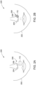
- Figures 2A-B are positions 200, 220 of various embodiments of the respiratory sensor 110 with respect to a patient 202.
- the positions 200, 220 of the respiratory sensor 110 are shown having the respiratory sensor 110 within the airflow path of the patient 202.
- the airflow path may be aligned and/or proximate to the nostrils 204, 206 of a nose 208 of the patient 202.
- ambient air is inhaled through the nostrils 204, 206 and subsequently exhaled through the nostrils 204, 206.
- Figure 2A illustrates the respiratory sensor 110 positioned below one of the nostrils 206. As ambient air is inhaled and/or exhaled through the nostrils 206, the respiratory sensor 110 is exposed to the flow of the ambient air traversing the nostril 206.
- Figure 2B illustrates the respiratory sensor 110 coupled to one of the nostrils 206.
- the respiratory sensor 110 may include a coil (e.g., inductor) configured to mechanically couple the respiratory sensor 110 to the nostril 206.
- a coil e.g., inductor
- the respiratory sensor 110 is exposed to the flow of the ambient air traversing the nostril 206.
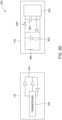
- the transmission circuit 112 may be configured to transmit an excitation signal and/or receive the response generated by the respiratory sensor 110 utilizing body-coupled communication (BBC).
- BBC body-coupled communication
- the transmission circuit 112 may represent a capacitor having each terminal of the capacitor in contact with the body.
- this body-coupled communication is referred to as "near-field intra-body communication”.
- the BBC communication is described in U.S. Patent Nos. 6,992,565, 6,777,992 , 6,223,018, 5,914,701 , and 8,633,809 , which are incorporated herein by reference in their entireties.
- the BCC enables the transmission circuit 112 and the respirator sensor 110 to exchange information through capacitive or galvanic coupling.
- the transmission circuit 112 may be positioned proximate to the respirator sensor 110 such that an RF circuit of the respiratory sensor 110 is positioned within the magnetic field.
- the RF circuit may include an antenna (e.g., inductor, coil) configured to generate a current when positioned within the magnetic field of the transmission circuit 112. The current generated by the RF circuit may supply power to the other components of the respiratory sensor 110.
- the transmission circuit 112 and the respiratory sensor 110 are communicatively coupled with each other.
- the controller circuit 102 may be configured to generate the excitation signal, which is transmitted by the transmission circuit 110.
- the excitation signal may represent a sinusoidal and/or digital signal having a set of predetermined electrical characteristics.
- the predetermined electrical characteristics may represent an amplitude, frequency, and/or the like of the excitation pulse.
- FIGS 3A-D are schematic diagrams 300, 330, 360, 370 of various embodiments of the respiratory sensor 110.
- each schematic diagram 300, 330, 360, 370 may include at least one of a capacitor 302, an inductor 304, and/or a resistor 306.
- the temperature coefficient may be ⁇ 100 parts per million (ppm) having a reference temperature of 25 degrees Celsius.
- the temperature of the capacitor 302 increases to approximately 36 degrees Celsius (e.g., temperature change of 11 degrees Celsius), which shifts the capacitance of the capacitor 302 based on the temperature coefficient.
- the capacitor 302 may be 2 pF based on the temperature change of 11 degrees and the temperature coefficient of ⁇ 1000 ppm the capacitance of the capacitor 302 may be adjusted by ⁇ 0.022 pF (e.g., 2.022 pF, 1.978 pF).
- the adjustment in the capacitance of the capacitor 302 adjusts the resonance frequency of the respiratory sensor 110 based on the inductor 304 and the capacitor 302.
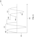
- Figure 4 is a graphical illustration 400 of the excitation signal 406 and the response 408, in accordance with an embodiment.
- the excitation signal 406 and the response 408 are shown along a horizontal axis 402 representing time.
- a vertical axis 404 may represent an amplitude (e.g., voltage, current).
- the excitation signal 406 is configured by the controller circuit 102 and transmitted by the transmission circuit 112.
- the excitation signal 406 is shown as a sinusoidal waveform in the graphical illustration 400, however in various embodiments the excitation signal 406 may be a digital and/or binary signal.
- the excitation signal 406 may have a set of predetermined electrical characteristics.
- the controller circuit 102 may configure the excitation signal 406 to have a frequency of 10 MHz having a period 410. It may noted that the excitation signal 406 may have a different frequency than 10 MHz such as greater than 1 MHz (e.g., 100 MHz, 400 MHz, 1 GHz).
- the transmission circuit 112 receives the response 408 generated by the respiratory sensor 110.
- the response 408 represents a modified reflection of the excitation signal 406 based on the electrical characteristics of the respiratory sensor 110, such as the capacitor 302.
- the controller circuit 102 is configured to analyze the response 408 to determine the at least one of the temperature or flow rate of the airflow path based on the temperature coefficient of the capacitor 302.
- the change in amplitude 502 is based on the resistance of the resistor 306. Based on the change in amplitude the controller circuit 102 may calculate the change in resistance of the resistor 306 relative to the resistance value stored in the memory 108.
- the memory 108 may store the electrical characteristics of the inductor 304, the capacitor 302, the resistor 306, and the temperature coefficients of the resistor and capacitor.
- the controller circuit 102 utilizing the adjusted resistance may determine the temperature of the respiratory sensor 110 representing a temperature of the airflow path based on the temperature coefficient and the electrical characteristics of the respiratory sensor 110. Additionally alternatively, the controller circuit 102 may compare the temperature value determined from the capacitance (e.g., change in frequency) and the resistance (e.g., change in amplitude). For example, the controller circuit 102 may calculate an average temperature value of the respiratory sensor 110 based on the temperature determinations from the change in frequency and change in amplitude.
- the respiratory sensor 110 may have at least one of the capacitor 302, the inductor 304, and the resistor 306.
- the schematic diagram 360 illustrates the respiratory sensor 110 having the inductor 304 and the resistor 306.
- the controller circuit 102 may determine the temperature and/or flow rate based on changes in the electrical characteristics, such as the change in amplitude of the response relative to the excitation signal.
- the controller circuit 102 may calculate a respiratory rate based on the temperature changes.
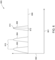
- Figure 6 is a graphical illustration 600 of temperature changes of the respiratory sensor 110, in accordance with an embodiment.
- the temperature changes are plotted along a horizontal axis 601 representing time and a vertical axis 602 representing temperature.
- the temperature changes are illustrated as temperature peaks 603-606.
- the peaks 603-606 may correspond to a series of temperature values determined by the controller circuit 102 based on the electrical characteristics of the respiratory sensor 110.
- the excitation signal 406 may be continually and/or repeatedly transmitted by the transmission circuit 112 at a sample rate and/or set period of time.
- the controller circuit 102 may generate the excitation signal 406, which is transmitted by the transmission circuit 112, every 50 ms.
- the controller circuit 102 may determine a flow rate based on the electrical characteristics of the respiratory sensor 110.
- the flow rate of the ambient air along the airflow path corresponds to a rate of temperature change of the respiratory sensor 110.
- the rate of temperature change may be based on a peak time 612.
- the peak time 612 may represent a length of time for the temperature of the respiratory sensor 110 to transition from a first temperature (e.g., the room temperature 608) to a second temperate (e.g., a peak temperature 614).
- a surface area of the respiratory sensor 110 within the airflow path may be stored in the memory 108.
- the surface area may represent a surface area of the capacitor 302 and/or the resistor 306. Based on a rate of temperature change and the surface area, the controller circuit 102 may determine a flowrate.
Landscapes
- Health & Medical Sciences (AREA)
- Life Sciences & Earth Sciences (AREA)
- Engineering & Computer Science (AREA)
- Animal Behavior & Ethology (AREA)
- Public Health (AREA)
- Pathology (AREA)
- Physics & Mathematics (AREA)
- Biomedical Technology (AREA)
- Heart & Thoracic Surgery (AREA)
- Medical Informatics (AREA)
- Molecular Biology (AREA)
- Surgery (AREA)
- Veterinary Medicine (AREA)
- General Health & Medical Sciences (AREA)
- Biophysics (AREA)
- Physiology (AREA)
- Pulmonology (AREA)
- Otolaryngology (AREA)
- Computer Networks & Wireless Communication (AREA)
- Artificial Intelligence (AREA)
- Computer Vision & Pattern Recognition (AREA)
- Psychiatry (AREA)
- Signal Processing (AREA)
- Measurement Of The Respiration, Hearing Ability, Form, And Blood Characteristics Of Living Organisms (AREA)
- Measuring And Recording Apparatus For Diagnosis (AREA)
Claims (14)
- Système de surveillance respiratoire (100) comprenant :un capteur respiratoire (110) configuré pour être positionné dans une voie d'écoulement d'air d'un patient (202), le capteur respiratoire (110) ayant une caractéristique électrique qui varie sur la base d'une propriété d'intérêt de la voie d'écoulement d'air, le capteur respiratoire (110) comprenant un circuit de communication couplé de manière communicative au circuit de transmission (112) en utilisant un canal de communication à l'intérieur d'un corps du patient (202), le circuit de communication et le circuit de transmission (112) étant en contact avec le corps ; etun circuit de transmission (112) configuré pour être couplé de manière communicative au capteur respiratoire (110), le circuit de transmission (112) étant configuré pour transmettre un signal d'excitation sans fil ou sur le corps (406) au capteur respiratoire (110), le capteur respiratoire (110) étant configuré pour générer une réponse basée sur le signal d'excitation (406) et la caractéristique électrique.
- Système de surveillance respiratoire (100) selon la revendication 1, la réponse correspondant au signal d'excitation (406) modifié par la caractéristique électrique.
- Système de surveillance respiratoire (100) selon la revendication 1, comprenant en outre un circuit de dispositif de commande (102) couplé de manière opérationnelle au circuit de transmission (112), le circuit de dispositif de commande (102) étant configuré pour déterminer au moins une température ou un débit de la voie d'écoulement de l'air sur la base de la caractéristique électrique.
- Système de surveillance respiratoire (100) selon la revendication 3, le capteur respiratoire (110) comprenant au moins un élément parmi un condensateur (302), une résistance (306) ou un inducteur (304) ayant un coefficient de température prédéterminé qui représente la caractéristique électrique, le circuit de dispositif de commande (102) étant configuré pour analyser la réponse afin de déterminer l'au moins un parmi la température ou le débit de la voie d'écoulement de l'air sur la base du coefficient de température prédéterminé.
- Système de surveillance respiratoire (100) selon la revendication 4, le circuit de dispositif de commande (102) étant configuré pour identifier une différence entre le signal d'excitation (406) et la réponse afin de déterminer au moins l'un parmi la température ou le débit sur la base de la différence.
- Système de surveillance respiratoire (100) selon la revendication 1, le capteur respiratoire (110) et le circuit de transmission (112) comprenant des circuits RF, le circuit RF du capteur respiratoire (110) étant configuré pour recevoir le signal d'excitation (406).
- Système de surveillance respiratoire (100) selon la revendication 1, la caractéristique électrique représentant une fréquence ou une amplitude ajustée du signal d'excitation.
- Procédé de surveillance respiratoire d'un patient, utilisant le système selon n'importe quelle revendication précédente, le procédé comprenant :le positionnement du circuit de transmission et du capteur respiratoire en contact avec le corps du patient, le capteur respiratoire comprenant un circuit de communication couplé au circuit de transmission par l'intermédiaire d'un canal de communication à l'intérieur du corps du patient ;l'ajustement d'une caractéristique électrique d'un capteur respiratoire sur la base d'une propriété d'intérêt d'une voie d'écoulement d'air ;la transmission, à partir du circuit de transmission, d'un signal d'excitation sans fil ou sur le corps au capteur respiratoire ;la réception, au niveau du capteur respiratoire, du signal d'excitation ;la génération d'une réponse basée sur le signal d'excitation et la caractéristique électrique.
- Procédé selon la revendication 8, comprenant en outre la détermination d'au moins un parmi une température ou un débit de la voie d'écoulement d'air sur la base de la caractéristique électrique et l'identification d'une différence entre le signal d'excitation et la réponse, l'opération de détermination étant basée sur la différence.
- Procédé selon la revendication 8, l'opération de génération comprenant la modification du signal d'excitation sur la base de la caractéristique électrique.
- Procédé selon la revendication 8, comprenant en outre le positionnement du capteur respiratoire dans une voie d'écoulement d'air d'un patient.
- Procédé selon la revendication 8, le capteur respiratoire comprenant au moins l'un parmi un condensateur, une résistance ou un inducteur ayant un coefficient de température prédéterminé qui représente la caractéristique électrique.
- Procédé selon la revendication 8,
le capteur respiratoire et le circuit de transmission comprenant des circuits RF, l'opération de réception comprenant la réception du signal d'excitation provenant du circuit RF du capteur respiratoire. - Procédé selon la revendication 8, la caractéristique électrique représentant une fréquence ou une amplitude ajustée du signal d'excitation.
Applications Claiming Priority (2)
| Application Number | Priority Date | Filing Date | Title |
|---|---|---|---|
| US15/385,259 US10987025B2 (en) | 2016-12-20 | 2016-12-20 | Systems and methods for a respiratory sensor |
| PCT/US2017/066402 WO2018118643A1 (fr) | 2016-12-20 | 2017-12-14 | Systèmes et procédés pour un capteur respiratoire |
Publications (2)
| Publication Number | Publication Date |
|---|---|
| EP3558098A1 EP3558098A1 (fr) | 2019-10-30 |
| EP3558098B1 true EP3558098B1 (fr) | 2024-07-10 |
Family
ID=61007790
Family Applications (1)
| Application Number | Title | Priority Date | Filing Date |
|---|---|---|---|
| EP17832634.4A Active EP3558098B1 (fr) | 2016-12-20 | 2017-12-14 | Systèmes et procédés pour un capteur respiratoire |
Country Status (4)
| Country | Link |
|---|---|
| US (1) | US10987025B2 (fr) |
| EP (1) | EP3558098B1 (fr) |
| CN (1) | CN110300544B (fr) |
| WO (1) | WO2018118643A1 (fr) |
Families Citing this family (1)
| Publication number | Priority date | Publication date | Assignee | Title |
|---|---|---|---|---|
| CN111839461B (zh) * | 2020-07-27 | 2022-11-22 | 歌尔科技有限公司 | 一种传感器和智能穿戴设备 |
Citations (3)
| Publication number | Priority date | Publication date | Assignee | Title |
|---|---|---|---|---|
| US20100069769A1 (en) * | 2008-09-12 | 2010-03-18 | Dymedix Corporation | Wireless pyro/piezo sensor base station |
| WO2016065180A1 (fr) * | 2014-10-22 | 2016-04-28 | President And Fellows Of Harvard College | Détection de gaz et de respiration par la conductivité d'eau dans un capteur de substrat poreux |
| US20160338624A1 (en) * | 2015-05-18 | 2016-11-24 | Pacesetter, Inc. | Device and Method for Sensing Blood Glucose |
Family Cites Families (17)
| Publication number | Priority date | Publication date | Assignee | Title |
|---|---|---|---|---|
| EP0824799B1 (fr) | 1995-05-08 | 2002-08-21 | Massachusetts Institute Of Technology | Dispositif de detection sans contact et de signalisation par courants intra-corporels induits par une source exterieure |
| US6223018B1 (en) | 1996-12-12 | 2001-04-24 | Nippon Telegraph And Telephone Corporation | Intra-body information transfer device |
| EP1045947B1 (fr) | 1998-09-14 | 2005-01-26 | Koninklijke Philips Electronics N.V. | Systeme de communication electronique |
| DE60102331T2 (de) | 2000-09-08 | 2005-03-17 | Matsushita Electric Works, Ltd., Kadoma | Datenübertragungssystem unter Verwendung eines menschlichen Körpers als Signalübertragungsweg |
| US6777992B2 (en) | 2002-04-04 | 2004-08-17 | The Regents Of The University Of Michigan | Low-power CMOS flip-flop |
| JP2007209597A (ja) * | 2006-02-10 | 2007-08-23 | Ngk Spark Plug Co Ltd | 呼吸状態監視装置、呼吸センサ、及び呼吸状態監視システム |
| US8308641B2 (en) * | 2006-02-28 | 2012-11-13 | Koninklijke Philips Electronics N.V. | Biometric monitor with electronics disposed on or in a neck collar |
| US20090112115A1 (en) * | 2007-10-29 | 2009-04-30 | Jung-Tang Huang | Apparatus for detecting human's breathing |
| EP2241033B1 (fr) * | 2007-12-20 | 2017-06-14 | Koninklijke Philips N.V. | Diversité d'électrode pour des systèmes de communication couplés au corps |
| WO2009149336A2 (fr) * | 2008-06-06 | 2009-12-10 | Salter Labs | Capteur de température adaptatif pour dispositif de surveillance de la respiration |
| US20090306528A1 (en) * | 2008-06-06 | 2009-12-10 | Salter Labs | Adaptive temperature sensor for breath monitoring device |
| WO2009158421A1 (fr) * | 2008-06-24 | 2009-12-30 | Dymedix Corporation | Adaptateur d’informations de pression et de température d’air respiratoire |
| US8434479B2 (en) * | 2009-02-27 | 2013-05-07 | Covidien Lp | Flow rate compensation for transient thermal response of hot-wire anemometers |
| WO2011019091A1 (fr) * | 2009-08-13 | 2011-02-17 | 帝人ファーマ株式会社 | Dispositif de calcul d'informations de forme d'onde respiratoire et dispositif médical utilisant des informations de forme d'onde respiratoire |
| US8907287B2 (en) * | 2010-12-01 | 2014-12-09 | Hill-Rom Services, Inc. | Patient monitoring system |
| CN103424133B (zh) * | 2012-05-10 | 2018-07-17 | 飞利浦知识产权企业有限公司 | 用于测量无线传感器中的可变阻抗元件的系统和方法 |
| US20150295562A1 (en) * | 2014-04-11 | 2015-10-15 | Mangilal Agarwal | Low Power Wireless Sensor System with Ring Oscillator And Sensors for Use in Monitoring of Physiological Data |
-
2016
- 2016-12-20 US US15/385,259 patent/US10987025B2/en active Active
-
2017
- 2017-12-14 EP EP17832634.4A patent/EP3558098B1/fr active Active
- 2017-12-14 WO PCT/US2017/066402 patent/WO2018118643A1/fr not_active Ceased
- 2017-12-14 CN CN201780085620.1A patent/CN110300544B/zh active Active
Patent Citations (3)
| Publication number | Priority date | Publication date | Assignee | Title |
|---|---|---|---|---|
| US20100069769A1 (en) * | 2008-09-12 | 2010-03-18 | Dymedix Corporation | Wireless pyro/piezo sensor base station |
| WO2016065180A1 (fr) * | 2014-10-22 | 2016-04-28 | President And Fellows Of Harvard College | Détection de gaz et de respiration par la conductivité d'eau dans un capteur de substrat poreux |
| US20160338624A1 (en) * | 2015-05-18 | 2016-11-24 | Pacesetter, Inc. | Device and Method for Sensing Blood Glucose |
Also Published As
| Publication number | Publication date |
|---|---|
| CN110300544B (zh) | 2022-07-26 |
| CN110300544A (zh) | 2019-10-01 |
| US20180168483A1 (en) | 2018-06-21 |
| WO2018118643A1 (fr) | 2018-06-28 |
| EP3558098A1 (fr) | 2019-10-30 |
| US10987025B2 (en) | 2021-04-27 |
Similar Documents
| Publication | Publication Date | Title |
|---|---|---|
| Wang et al. | Rf-ecg: Heart rate variability assessment based on cots rfid tag array | |
| CN111264015B (zh) | 无线电力传输装置及其控制方法 | |
| CN106999090B (zh) | 用于估计生理特性的值的装置和方法 | |
| US20200386879A1 (en) | Detection and identification of a human from characteristic signals | |
| US11259715B2 (en) | Monitoring and diagnostics systems and methods | |
| EP3565476B1 (fr) | Système et procédé de focalisation dynamique sur le coeur et/ou les poumons par accord de fréquence et analyse de phase d'impédance et/ou variations de magnitude | |
| EP3384843B1 (fr) | Détermination des attributs respiratoires par un dispositif de détection | |
| JP2019512304A (ja) | バイタルサインを検出及び監視する方法、装置、サーバ及びシステム | |
| CN101578064A (zh) | 用于确定医疗器械的位置的系统 | |
| US9882610B1 (en) | Near field communication sensor system | |
| KR20180088156A (ko) | 체내 이식형 혈당 측정 장치 및 방법 | |
| EP4099897A1 (fr) | Système, procédé et produit-programme informatique pour la mesure à distance de signes vitaux | |
| EP3488778B1 (fr) | Dispositif de caractérisation structurale électromagnétique | |
| EP3558098B1 (fr) | Systèmes et procédés pour un capteur respiratoire | |
| EP3214409B1 (fr) | Capteur inductif pour la mesure de position/ orientation | |
| Konings et al. | Improved distance metrics for histogram-based device-free localization | |
| US20120101773A1 (en) | Method and device for measuring conductivity information and corresponding markers | |
| WO2017157989A1 (fr) | Procédé, système et appareil pour mesurer une caractéristique physiologique d'un sujet | |
| US20230404418A1 (en) | System and method for cardiovascular health monitoring | |
| EP4287664A1 (fr) | Procédé et appareil de communication sans fil | |
| KR20220156198A (ko) | 생체 정보 측정 시스템 및 방법 | |
| AU2022319629B2 (en) | Livestock heart rate measurement with bolus sensor | |
| EP3811863A1 (fr) | Utilisation de la modulation d'amplitude (ma) de signal d'électrocardiogramme (ecg) enregistré par un implant pour surveiller la respiration | |
| KR20250121750A (ko) | 비접촉 수면 무호흡 감지 시스템 | |
| Caldara et al. | Development of a potentially implantable pressure sensing platform with RFID interface |
Legal Events
| Date | Code | Title | Description |
|---|---|---|---|
| STAA | Information on the status of an ep patent application or granted ep patent |
Free format text: STATUS: UNKNOWN |
|
| STAA | Information on the status of an ep patent application or granted ep patent |
Free format text: STATUS: THE INTERNATIONAL PUBLICATION HAS BEEN MADE |
|
| PUAI | Public reference made under article 153(3) epc to a published international application that has entered the european phase |
Free format text: ORIGINAL CODE: 0009012 |
|
| STAA | Information on the status of an ep patent application or granted ep patent |
Free format text: STATUS: REQUEST FOR EXAMINATION WAS MADE |
|
| 17P | Request for examination filed |
Effective date: 20190716 |
|
| AK | Designated contracting states |
Kind code of ref document: A1 Designated state(s): AL AT BE BG CH CY CZ DE DK EE ES FI FR GB GR HR HU IE IS IT LI LT LU LV MC MK MT NL NO PL PT RO RS SE SI SK SM TR |
|
| AX | Request for extension of the european patent |
Extension state: BA ME |
|
| DAV | Request for validation of the european patent (deleted) | ||
| DAX | Request for extension of the european patent (deleted) | ||
| STAA | Information on the status of an ep patent application or granted ep patent |
Free format text: STATUS: EXAMINATION IS IN PROGRESS |
|
| P01 | Opt-out of the competence of the unified patent court (upc) registered |
Effective date: 20230528 |
|
| 17Q | First examination report despatched |
Effective date: 20230710 |
|
| GRAP | Despatch of communication of intention to grant a patent |
Free format text: ORIGINAL CODE: EPIDOSNIGR1 |
|
| STAA | Information on the status of an ep patent application or granted ep patent |
Free format text: STATUS: GRANT OF PATENT IS INTENDED |
|
| INTG | Intention to grant announced |
Effective date: 20240313 |
|
| GRAS | Grant fee paid |
Free format text: ORIGINAL CODE: EPIDOSNIGR3 |
|
| GRAA | (expected) grant |
Free format text: ORIGINAL CODE: 0009210 |
|
| STAA | Information on the status of an ep patent application or granted ep patent |
Free format text: STATUS: THE PATENT HAS BEEN GRANTED |
|
| AK | Designated contracting states |
Kind code of ref document: B1 Designated state(s): AL AT BE BG CH CY CZ DE DK EE ES FI FR GB GR HR HU IE IS IT LI LT LU LV MC MK MT NL NO PL PT RO RS SE SI SK SM TR |
|
| REG | Reference to a national code |
Ref country code: CH Ref legal event code: EP |
|
| REG | Reference to a national code |
Ref country code: DE Ref legal event code: R096 Ref document number: 602017083234 Country of ref document: DE |
|
| REG | Reference to a national code |
Ref country code: LT Ref legal event code: MG9D |
|
| REG | Reference to a national code |
Ref country code: NL Ref legal event code: MP Effective date: 20240710 |
|
| PG25 | Lapsed in a contracting state [announced via postgrant information from national office to epo] |
Ref country code: PT Free format text: LAPSE BECAUSE OF FAILURE TO SUBMIT A TRANSLATION OF THE DESCRIPTION OR TO PAY THE FEE WITHIN THE PRESCRIBED TIME-LIMIT Effective date: 20241111 |
|
| REG | Reference to a national code |
Ref country code: AT Ref legal event code: MK05 Ref document number: 1701269 Country of ref document: AT Kind code of ref document: T Effective date: 20240710 |
|
| PG25 | Lapsed in a contracting state [announced via postgrant information from national office to epo] |
Ref country code: NL Free format text: LAPSE BECAUSE OF FAILURE TO SUBMIT A TRANSLATION OF THE DESCRIPTION OR TO PAY THE FEE WITHIN THE PRESCRIBED TIME-LIMIT Effective date: 20240710 |
|
| PG25 | Lapsed in a contracting state [announced via postgrant information from national office to epo] |
Ref country code: PT Free format text: LAPSE BECAUSE OF FAILURE TO SUBMIT A TRANSLATION OF THE DESCRIPTION OR TO PAY THE FEE WITHIN THE PRESCRIBED TIME-LIMIT Effective date: 20241111 Ref country code: NL Free format text: LAPSE BECAUSE OF FAILURE TO SUBMIT A TRANSLATION OF THE DESCRIPTION OR TO PAY THE FEE WITHIN THE PRESCRIBED TIME-LIMIT Effective date: 20240710 |
|
| PGFP | Annual fee paid to national office [announced via postgrant information from national office to epo] |
Ref country code: DE Payment date: 20241121 Year of fee payment: 8 |
|
| PG25 | Lapsed in a contracting state [announced via postgrant information from national office to epo] |
Ref country code: NO Free format text: LAPSE BECAUSE OF FAILURE TO SUBMIT A TRANSLATION OF THE DESCRIPTION OR TO PAY THE FEE WITHIN THE PRESCRIBED TIME-LIMIT Effective date: 20241010 |
|
| PG25 | Lapsed in a contracting state [announced via postgrant information from national office to epo] |
Ref country code: GR Free format text: LAPSE BECAUSE OF FAILURE TO SUBMIT A TRANSLATION OF THE DESCRIPTION OR TO PAY THE FEE WITHIN THE PRESCRIBED TIME-LIMIT Effective date: 20241011 Ref country code: FI Free format text: LAPSE BECAUSE OF FAILURE TO SUBMIT A TRANSLATION OF THE DESCRIPTION OR TO PAY THE FEE WITHIN THE PRESCRIBED TIME-LIMIT Effective date: 20240710 Ref country code: PL Free format text: LAPSE BECAUSE OF FAILURE TO SUBMIT A TRANSLATION OF THE DESCRIPTION OR TO PAY THE FEE WITHIN THE PRESCRIBED TIME-LIMIT Effective date: 20240710 |
|
| PGFP | Annual fee paid to national office [announced via postgrant information from national office to epo] |
Ref country code: GB Payment date: 20241122 Year of fee payment: 8 |
|
| PG25 | Lapsed in a contracting state [announced via postgrant information from national office to epo] |
Ref country code: BG Free format text: LAPSE BECAUSE OF FAILURE TO SUBMIT A TRANSLATION OF THE DESCRIPTION OR TO PAY THE FEE WITHIN THE PRESCRIBED TIME-LIMIT Effective date: 20240710 |
|
| PGFP | Annual fee paid to national office [announced via postgrant information from national office to epo] |
Ref country code: FR Payment date: 20241121 Year of fee payment: 8 |
|
| PG25 | Lapsed in a contracting state [announced via postgrant information from national office to epo] |
Ref country code: LV Free format text: LAPSE BECAUSE OF FAILURE TO SUBMIT A TRANSLATION OF THE DESCRIPTION OR TO PAY THE FEE WITHIN THE PRESCRIBED TIME-LIMIT Effective date: 20240710 |
|
| PG25 | Lapsed in a contracting state [announced via postgrant information from national office to epo] |
Ref country code: IS Free format text: LAPSE BECAUSE OF FAILURE TO SUBMIT A TRANSLATION OF THE DESCRIPTION OR TO PAY THE FEE WITHIN THE PRESCRIBED TIME-LIMIT Effective date: 20241110 Ref country code: AT Free format text: LAPSE BECAUSE OF FAILURE TO SUBMIT A TRANSLATION OF THE DESCRIPTION OR TO PAY THE FEE WITHIN THE PRESCRIBED TIME-LIMIT Effective date: 20240710 |
|
| PG25 | Lapsed in a contracting state [announced via postgrant information from national office to epo] |
Ref country code: HR Free format text: LAPSE BECAUSE OF FAILURE TO SUBMIT A TRANSLATION OF THE DESCRIPTION OR TO PAY THE FEE WITHIN THE PRESCRIBED TIME-LIMIT Effective date: 20240710 |
|
| PG25 | Lapsed in a contracting state [announced via postgrant information from national office to epo] |
Ref country code: ES Free format text: LAPSE BECAUSE OF FAILURE TO SUBMIT A TRANSLATION OF THE DESCRIPTION OR TO PAY THE FEE WITHIN THE PRESCRIBED TIME-LIMIT Effective date: 20240710 Ref country code: RS Free format text: LAPSE BECAUSE OF FAILURE TO SUBMIT A TRANSLATION OF THE DESCRIPTION OR TO PAY THE FEE WITHIN THE PRESCRIBED TIME-LIMIT Effective date: 20241010 |
|
| PG25 | Lapsed in a contracting state [announced via postgrant information from national office to epo] |
Ref country code: RS Free format text: LAPSE BECAUSE OF FAILURE TO SUBMIT A TRANSLATION OF THE DESCRIPTION OR TO PAY THE FEE WITHIN THE PRESCRIBED TIME-LIMIT Effective date: 20241010 Ref country code: PL Free format text: LAPSE BECAUSE OF FAILURE TO SUBMIT A TRANSLATION OF THE DESCRIPTION OR TO PAY THE FEE WITHIN THE PRESCRIBED TIME-LIMIT Effective date: 20240710 Ref country code: NO Free format text: LAPSE BECAUSE OF FAILURE TO SUBMIT A TRANSLATION OF THE DESCRIPTION OR TO PAY THE FEE WITHIN THE PRESCRIBED TIME-LIMIT Effective date: 20241010 Ref country code: LV Free format text: LAPSE BECAUSE OF FAILURE TO SUBMIT A TRANSLATION OF THE DESCRIPTION OR TO PAY THE FEE WITHIN THE PRESCRIBED TIME-LIMIT Effective date: 20240710 Ref country code: IS Free format text: LAPSE BECAUSE OF FAILURE TO SUBMIT A TRANSLATION OF THE DESCRIPTION OR TO PAY THE FEE WITHIN THE PRESCRIBED TIME-LIMIT Effective date: 20241110 Ref country code: HR Free format text: LAPSE BECAUSE OF FAILURE TO SUBMIT A TRANSLATION OF THE DESCRIPTION OR TO PAY THE FEE WITHIN THE PRESCRIBED TIME-LIMIT Effective date: 20240710 Ref country code: GR Free format text: LAPSE BECAUSE OF FAILURE TO SUBMIT A TRANSLATION OF THE DESCRIPTION OR TO PAY THE FEE WITHIN THE PRESCRIBED TIME-LIMIT Effective date: 20241011 Ref country code: FI Free format text: LAPSE BECAUSE OF FAILURE TO SUBMIT A TRANSLATION OF THE DESCRIPTION OR TO PAY THE FEE WITHIN THE PRESCRIBED TIME-LIMIT Effective date: 20240710 Ref country code: ES Free format text: LAPSE BECAUSE OF FAILURE TO SUBMIT A TRANSLATION OF THE DESCRIPTION OR TO PAY THE FEE WITHIN THE PRESCRIBED TIME-LIMIT Effective date: 20240710 Ref country code: BG Free format text: LAPSE BECAUSE OF FAILURE TO SUBMIT A TRANSLATION OF THE DESCRIPTION OR TO PAY THE FEE WITHIN THE PRESCRIBED TIME-LIMIT Effective date: 20240710 Ref country code: AT Free format text: LAPSE BECAUSE OF FAILURE TO SUBMIT A TRANSLATION OF THE DESCRIPTION OR TO PAY THE FEE WITHIN THE PRESCRIBED TIME-LIMIT Effective date: 20240710 |
|
| REG | Reference to a national code |
Ref country code: DE Ref legal event code: R097 Ref document number: 602017083234 Country of ref document: DE |
|
| PG25 | Lapsed in a contracting state [announced via postgrant information from national office to epo] |
Ref country code: SM Free format text: LAPSE BECAUSE OF FAILURE TO SUBMIT A TRANSLATION OF THE DESCRIPTION OR TO PAY THE FEE WITHIN THE PRESCRIBED TIME-LIMIT Effective date: 20240710 Ref country code: RO Free format text: LAPSE BECAUSE OF FAILURE TO SUBMIT A TRANSLATION OF THE DESCRIPTION OR TO PAY THE FEE WITHIN THE PRESCRIBED TIME-LIMIT Effective date: 20240710 Ref country code: DK Free format text: LAPSE BECAUSE OF FAILURE TO SUBMIT A TRANSLATION OF THE DESCRIPTION OR TO PAY THE FEE WITHIN THE PRESCRIBED TIME-LIMIT Effective date: 20240710 |
|
| PG25 | Lapsed in a contracting state [announced via postgrant information from national office to epo] |
Ref country code: EE Free format text: LAPSE BECAUSE OF FAILURE TO SUBMIT A TRANSLATION OF THE DESCRIPTION OR TO PAY THE FEE WITHIN THE PRESCRIBED TIME-LIMIT Effective date: 20240710 |
|
| PG25 | Lapsed in a contracting state [announced via postgrant information from national office to epo] |
Ref country code: CZ Free format text: LAPSE BECAUSE OF FAILURE TO SUBMIT A TRANSLATION OF THE DESCRIPTION OR TO PAY THE FEE WITHIN THE PRESCRIBED TIME-LIMIT Effective date: 20240710 |
|
| PG25 | Lapsed in a contracting state [announced via postgrant information from national office to epo] |
Ref country code: SK Free format text: LAPSE BECAUSE OF FAILURE TO SUBMIT A TRANSLATION OF THE DESCRIPTION OR TO PAY THE FEE WITHIN THE PRESCRIBED TIME-LIMIT Effective date: 20240710 Ref country code: IT Free format text: LAPSE BECAUSE OF FAILURE TO SUBMIT A TRANSLATION OF THE DESCRIPTION OR TO PAY THE FEE WITHIN THE PRESCRIBED TIME-LIMIT Effective date: 20240710 |
|
| PLBE | No opposition filed within time limit |
Free format text: ORIGINAL CODE: 0009261 |
|
| STAA | Information on the status of an ep patent application or granted ep patent |
Free format text: STATUS: NO OPPOSITION FILED WITHIN TIME LIMIT |
|
| 26N | No opposition filed |
Effective date: 20250411 |
|
| PG25 | Lapsed in a contracting state [announced via postgrant information from national office to epo] |
Ref country code: MC Free format text: LAPSE BECAUSE OF FAILURE TO SUBMIT A TRANSLATION OF THE DESCRIPTION OR TO PAY THE FEE WITHIN THE PRESCRIBED TIME-LIMIT Effective date: 20240710 |
|
| REG | Reference to a national code |
Ref country code: DE Ref legal event code: R081 Ref document number: 602017083234 Country of ref document: DE Owner name: GE PRECISION HEALTHCARE LLC, WAUKESHA, US Free format text: FORMER OWNER: GENERAL ELECTRIC COMPANY, SCHENECTADY, NY, US |
|
| REG | Reference to a national code |
Ref country code: CH Ref legal event code: PL |
|
| PG25 | Lapsed in a contracting state [announced via postgrant information from national office to epo] |
Ref country code: LU Free format text: LAPSE BECAUSE OF NON-PAYMENT OF DUE FEES Effective date: 20241214 |
|
| REG | Reference to a national code |
Ref country code: GB Ref legal event code: 732E Free format text: REGISTERED BETWEEN 20250807 AND 20250813 |
|
| PG25 | Lapsed in a contracting state [announced via postgrant information from national office to epo] |
Ref country code: SE Free format text: LAPSE BECAUSE OF FAILURE TO SUBMIT A TRANSLATION OF THE DESCRIPTION OR TO PAY THE FEE WITHIN THE PRESCRIBED TIME-LIMIT Effective date: 20240710 |
|
| REG | Reference to a national code |
Ref country code: BE Ref legal event code: MM Effective date: 20241231 |
|
| PG25 | Lapsed in a contracting state [announced via postgrant information from national office to epo] |
Ref country code: BE Free format text: LAPSE BECAUSE OF NON-PAYMENT OF DUE FEES Effective date: 20241231 |
|
| PG25 | Lapsed in a contracting state [announced via postgrant information from national office to epo] |
Ref country code: CH Free format text: LAPSE BECAUSE OF NON-PAYMENT OF DUE FEES Effective date: 20241231 |
|
| PG25 | Lapsed in a contracting state [announced via postgrant information from national office to epo] |
Ref country code: IE Free format text: LAPSE BECAUSE OF NON-PAYMENT OF DUE FEES Effective date: 20241214 |