EP3558096B1 - Dispositif d'oxymétrie de pouls à capteur de poignet - Google Patents
Dispositif d'oxymétrie de pouls à capteur de poignet Download PDFInfo
- Publication number
- EP3558096B1 EP3558096B1 EP17829296.7A EP17829296A EP3558096B1 EP 3558096 B1 EP3558096 B1 EP 3558096B1 EP 17829296 A EP17829296 A EP 17829296A EP 3558096 B1 EP3558096 B1 EP 3558096B1
- Authority
- EP
- European Patent Office
- Prior art keywords
- detector
- light
- wearer
- wrist
- pulse oximetry
- Prior art date
- Legal status (The legal status is an assumption and is not a legal conclusion. Google has not performed a legal analysis and makes no representation as to the accuracy of the status listed.)
- Active
Links
Images


Classifications
-
- A—HUMAN NECESSITIES
- A61—MEDICAL OR VETERINARY SCIENCE; HYGIENE
- A61B—DIAGNOSIS; SURGERY; IDENTIFICATION
- A61B5/00—Measuring for diagnostic purposes; Identification of persons
- A61B5/145—Measuring characteristics of blood in vivo, e.g. gas concentration or pH-value ; Measuring characteristics of body fluids or tissues, e.g. interstitial fluid or cerebral tissue
- A61B5/1455—Measuring characteristics of blood in vivo, e.g. gas concentration or pH-value ; Measuring characteristics of body fluids or tissues, e.g. interstitial fluid or cerebral tissue using optical sensors, e.g. spectral photometrical oximeters
- A61B5/14551—Measuring characteristics of blood in vivo, e.g. gas concentration or pH-value ; Measuring characteristics of body fluids or tissues, e.g. interstitial fluid or cerebral tissue using optical sensors, e.g. spectral photometrical oximeters for measuring blood gases
- A61B5/14552—Details of sensors specially adapted therefor
-
- A—HUMAN NECESSITIES
- A61—MEDICAL OR VETERINARY SCIENCE; HYGIENE
- A61B—DIAGNOSIS; SURGERY; IDENTIFICATION
- A61B5/00—Measuring for diagnostic purposes; Identification of persons
- A61B5/68—Arrangements of detecting, measuring or recording means, e.g. sensors, in relation to patient
- A61B5/6801—Arrangements of detecting, measuring or recording means, e.g. sensors, in relation to patient specially adapted to be attached to or worn on the body surface
- A61B5/6802—Sensor mounted on worn items
- A61B5/681—Wristwatch-type devices
-
- A—HUMAN NECESSITIES
- A61—MEDICAL OR VETERINARY SCIENCE; HYGIENE
- A61B—DIAGNOSIS; SURGERY; IDENTIFICATION
- A61B5/00—Measuring for diagnostic purposes; Identification of persons
- A61B5/68—Arrangements of detecting, measuring or recording means, e.g. sensors, in relation to patient
- A61B5/6801—Arrangements of detecting, measuring or recording means, e.g. sensors, in relation to patient specially adapted to be attached to or worn on the body surface
- A61B5/683—Means for maintaining contact with the body
- A61B5/6831—Straps, bands or harnesses
-
- A—HUMAN NECESSITIES
- A61—MEDICAL OR VETERINARY SCIENCE; HYGIENE
- A61B—DIAGNOSIS; SURGERY; IDENTIFICATION
- A61B5/00—Measuring for diagnostic purposes; Identification of persons
- A61B5/68—Arrangements of detecting, measuring or recording means, e.g. sensors, in relation to patient
- A61B5/6801—Arrangements of detecting, measuring or recording means, e.g. sensors, in relation to patient specially adapted to be attached to or worn on the body surface
- A61B5/683—Means for maintaining contact with the body
- A61B5/6834—Means for maintaining contact with the body using vacuum
-
- A—HUMAN NECESSITIES
- A61—MEDICAL OR VETERINARY SCIENCE; HYGIENE
- A61B—DIAGNOSIS; SURGERY; IDENTIFICATION
- A61B2562/00—Details of sensors; Constructional details of sensor housings or probes; Accessories for sensors
- A61B2562/18—Shielding or protection of sensors from environmental influences, e.g. protection from mechanical damage
- A61B2562/185—Optical shielding, e.g. baffles
-
- A—HUMAN NECESSITIES
- A61—MEDICAL OR VETERINARY SCIENCE; HYGIENE
- A61B—DIAGNOSIS; SURGERY; IDENTIFICATION
- A61B5/00—Measuring for diagnostic purposes; Identification of persons
- A61B5/02—Detecting, measuring or recording for evaluating the cardiovascular system, e.g. pulse, heart rate, blood pressure or blood flow
- A61B5/024—Measuring pulse rate or heart rate
- A61B5/02416—Measuring pulse rate or heart rate using photoplethysmograph signals, e.g. generated by infrared radiation
- A61B5/02427—Details of sensor
-
- A—HUMAN NECESSITIES
- A61—MEDICAL OR VETERINARY SCIENCE; HYGIENE
- A61B—DIAGNOSIS; SURGERY; IDENTIFICATION
- A61B5/00—Measuring for diagnostic purposes; Identification of persons
- A61B5/68—Arrangements of detecting, measuring or recording means, e.g. sensors, in relation to patient
- A61B5/6801—Arrangements of detecting, measuring or recording means, e.g. sensors, in relation to patient specially adapted to be attached to or worn on the body surface
- A61B5/6813—Specially adapted to be attached to a specific body part
- A61B5/6824—Arm or wrist
Definitions
- Embodiments of the present invention relate to a device (e.g., pulse oximetry device) that can be worn on a wrist and associated methods.
- a device e.g., pulse oximetry device
- Pulse oximetry may be used to measure various blood characteristics, such as the arterial blood oxygen saturation of hemoglobin (SPO2), and the rate of blood pulsations corresponding to each heartbeat of a patient.
- SPO2 arterial blood oxygen saturation of hemoglobin
- the pulse oximetry refers to the time varying amount of arterial blood at the measurement site during each cardiac cycle.
- Pulse oximeters typically utilize a non-invasive optical sensor that detects the light response from within a patient's tissue indicative of the amount of light absorbed within the tissue at the illuminated site. One or more of the above physiological characteristics may then be calculated based upon the amount of the absorbed light. More specifically, the light passed through the tissue is typically selected to be of one or more light wavelengths that may be absorbed by the blood in an amount correlative to the amount of the hemoglobin constituent present in the blood. The amount of light absorbed at different light wavelengths may then be used to estimate the arterial blood hemoglobin related parameters using various algorithms. Pulsatile changes in the volume of the arterial blood at the illuminated site during blood pressure wave propagation alter the intensity of the light response detected by the sensor's photodetector.
- Pulse oximetry techniques typically utilize a tissue site that is well perfused with blood, such as a patient's finger, toe, or earlobe, on which to place the sensor.
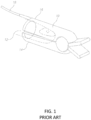
- Figure 1 illustrates a sensor 10 adapted to be placed on a finger 12 of a user, such as a patient, according to the prior art.
- the sensor 10 includes a clip formed of two portions 14 and 16 adapted to clip and constrain the sensor 10 to finger 12 while pulse oximetry measurements are taken.
- Sensors of a type similar to the sensor 10 are typically coupled to cables 18 that couple the sensor 10 to monitoring systems adapted to receive and process the signals from the sensor 10. Accordingly, such sensor using in continuous monitoring mode typically requires the patient (or user) to be confined to a certain area, in close vicinity of the monitoring system, thereby limiting patient mobility.
- pinch pressure applied by clip portions 14 and 16 on the finger 12 of the patient may overtime feel uncomfortable or become overbearing to the patient to the extent the patient may want to remove the sensor 10 and cease otherwise required monitoring.
- such sensors are not suitable for prolonged and continuous pulse oximetry measurements.
- pulse oximetry devices are no exception, as such devices may generally be prone to artifacts arising, for example, from patient motion, which may be random, voluntary or involuntary. Consequently, artifacts arising out of such circumstances can distort and skew obtained data, ultimately adversely affecting the quality of the pulse oximetry measurements.
- US 2014/200423 A1 discloses a wearable pulse oximetry device.
- a pulse oximetry device includes at least two light sources having different wavelengths, at least one detector responsive to said different wavelengths, a wrist strap, and a casing coupled to the wrist strap for housing the at least two light sources and the at least one detector.
- the wrist strap includes a projection (a generally concave projection) adapted to fit snugly against a wearer's wrist and remain in place even when the wearer is moving.
- the generally concave projection further comprises one or more ridges.
- the generally concave projection includes an elastomer material (e.g., silicon) having a softness (durometer) of between 30 to 75 Shore A (e.g., approximately 50 Shore A).
- the generally concave projection may include a hollow interior portion for receipt of medication.
- the wrist strap of a pulse oximetry device includes a first portion and a second portion adapted for attachment to the first portion (e.g., via a clasp) to fixate the wrist strap around a user's wrist.
- the first portion of the wrist strap includes the generally concave projection.
- the second portion of the wrist strap includes a second projection that assists to fixate the device at a fixated area corresponding to a distal end of the wearer's ulna bone.
- the second projection is a curved projection that generally follows a contour of the wearer's ulna bone.
- the second projection is formed generally in the shape of part of a dome or sphere.
- each of the at least two light sources and the at least one detector is positioned within the casing such that when the wrist strap is affixed around the wearer's wrist the least two light sources and the at least one detector are positioned adjacent to the distal end of the ulna and closer to the ulna than the radius, and the at least one detector is positioned to detect light emitted from the at least two light sources.
- Each of the at least two light sources and the at least one detector is angled generally toward a virtual center point of the distal end of a wearer's ulna bone and each of the at least two light sources and the at least one detector has a different axis.
- each of the at least two light sources and the at least one detector is positioned within the casing such that when the wrist strap is affixed around the wearer's wrist the least two light sources and the at least one detector are positioned adjacent to the distal end of the ulna and closer to the ulna than the radius, and the at least one detector is positioned to detect light emitted from the at least two light sources.
- At least one of the at least two light sources and the at least one detector of a pulse oximetry device includes a generally dome-shaped or conical-shaped structure that assists to fixate the pulse oximetry device, and its corresponding at least two light source(s) and at least one detector, at a fixated area at, adjacent to, or at a periphery of, a distal end of a wearer's ulna bone.
- a pulse oximetry device in some embodiments of the present invention, includes at least two light sources having different wavelengths, at least one detector responsive to said different wavelengths, a wrist strap, and a casing coupled to the wrist strap for housing the at least two light sources and the at least one detector, wherein the casing comprises a first portion and a second portion that extend at an angle relative to each other.
- a display may be fixed to the first portion of the casing, and the at least two light sources and the at least one detector may be fixed to the second portion of the casing.
- the first portion of the casing and the second portion of the casing together generally resemble the shape of the letter "L."
- the casing is strong enough to maintain the positioning of the at least two light sources and the at least one detector when the device is worn by a wearer, while simultaneously having slight pliability or elasticity to act as a movement dampening cushion that reduces measurement artifacts of the pulse oximetry device resulting from movement of the wearer.
- the casing includes a third portion that joins the first portion and the second portion of the casing, where the third portion allows for slight angular movement between the first portion and the second portion of the casing in response to normal forces while the pulse oximetry device is being worn by a user.
- the casing of the pulse oximetry device includes aluminum or thermoplastic urethane (TPU). In some embodiments, the casing has a durometer of between 25 Shore A and 35 Shore A.
- each of the at least two light sources and the at least one detector is positioned within the casing such that when the wrist strap is affixed around the wearer's wrist the least two light sources and the at least one detector are positioned adjacent to the distal end of the ulna and closer to the ulna than the radius, and the at least one detector is positioned to detect light emitted from the at least two light sources.
- the pulse oximetry device may include a pad that is mounted or otherwise fixed generally to an inner side of the casing, wherein the pad includes one or more barriers that function to fit snugly against a wearer's wrist and prevent stray light from entering a measuring area of the at least two light sources and the at least one detector when the pulse oximetry device is worn by a wearer.
- the at least two light sources and said at least one light detector of a pulse oximetry device may be disposed relative to one another such that emitted light is adapted to trans-illuminate via a wearer's ulna before reaching the at least one light detector.
- the at least two light sources and the at least one light detector may be disposed relative to one another such that the emitted light is adapted to reach the at least one light detector in a reflective mode.
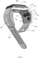
- FIG. 2 is a perspective view of a device 200 in accordance with an exemplary embodiment of the present invention.
- Device 200 may be a wrist-type oximeter device adapted to be worn on a wrist of a user, as further shown in Figure 2 .
- device 200 is adapted to obtain data including, for example, pulse data, oxygen saturation (SPO2) data, and/or other data from a user while the user wears device 200 on the wrist.
- SPO2 oxygen saturation
- a user can wear the device 200 in manner similar to that of wearing a watch, a wrist band or any article of clothing, ornament, or garment adapted to be worn on the wrist of the user.
- device 200 can be conveniently worn at any time or place by those users required to or wishing to obtain, for example, pulse oximetry and pulse rate data without being attached to elaborate monitoring device or being confined to certain monitoring areas.
- the device 200 is a self-contained, self-powered device adapted to obtain, analyze and process, for example, various light electromagnetic signals from which pulse oximetry data is ultimately obtained.
- Device 200 may further include wired or wireless interfaces whereby the device 200 can communicate and/or relay data signals to external and/or remote devices.
- device 200 can collect and provide the oximetry data to any remote users, institutions such as hospitals or clinics, or anyone who requires or has interest in such pulse oximetry data of the user.
- device 200 may include a display 202 that displays, for example, data measured by device 200. Such data may include pulse rate data (e.g., "PULSE 76"), and data regarding the wearer's blood oxygen saturation of hemoglobin (e.g., "SPO 2 97%").
- display 202 may be an LED display, such as, for example, an organic light-emitting diode (“OLED”) display, liquid crystal display (“LCD”), or any other suitable display.
- device 200 may include one or more physical buttons or user input interfaces (e.g., alphanumerical buttons or user interface where by the user can enter any combination of numbers and/or letters as desired or needed while the device is in use).
- buttons or user interface inputs may be placed at any side, or sides, of device 200 or any other area of device 200 that is accessible to the user.
- device 200 may alternatively or additionally measure and/or display other data, including, for example, data regarding one or more vital signs, data regarding one or more blood analytes, blood pressure data (e.g., "BP 117/76"), and/or data regarding stroke volume (e.g., "SV 73").
- device 200 includes a wrist strap or band (204a, 204b) that is adapted to extend around a wearer's wrist.
- the wrist band may be made up of any flexible and/or stretchable material, such as rubber, silicon, soft plastic, or cloth or any combination thereof for providing the user a comfortable fit and feeling while wearing the device 200.
- the wrist band may include first side 204a adapted to join with a second side 204b via a clasp 206, which may include, for example, a male attachment member for pairing with one or more suitable adjustment holes formed in wrist band 204a (as shown) based on the wearer's wrist size, a friction-fit clasp, or any other suitable attachment mechanism (e.g., hook and loop or velcro).
- a male attachment member for pairing with one or more suitable adjustment holes formed in wrist band 204a (as shown) based on the wearer's wrist size, a friction-fit clasp, or any other suitable attachment mechanism (e.g., hook and loop or velcro).
- wrist band 204a includes projection 208.
- Projection 208 may be adapted to dampen the effects of a wearer's movement on sensor measurements of device 200 and to fixate the device to a wearer's wrist when the two sides 204a and 204b of the wrist band are joined.
- projection 208 has an outer surface that is generally concave (see also e.g., Figure 4A , 12 , and 14 ). Such a contour may enable projection 208, and thus device 200, to fit snugly against the wearer's wrist and remain in place even when the wearer is moving.
- projection 208 includes one or more ridges 224 to further enable device 200 to fit snugly against the wearer's wrist and remain in place irrespective of whether the wearer is moving (see also e.g., Figures 4A , 12 and 14 ).
- Projection 208 may be made up of any flexible and/or stretchable material, such as rubber, silicon, soft plastic, or cloth or any combination thereof for providing the user a comfortable fit and feeling while wearing the device 200.
- projection 208 may be formed entirely from or otherwise include, at least in part (e.g., a coating), an elastomer material (e.g., silicon) having a softness (durometer) of between 30 to 75 Shore A (e.g., approximately 50 Shore A).
- projection 208 may be at least partially hollow and may contain a space, for example, for storage of emergency medicine such as one or more pills for emergency intervention.
- projection 208 may be integrally formed with or otherwise attached to wrist strap 204a.
- wrist strap 204a may contain an opening or seal 226 through which the emergency medicine may be inserted and accessed (see also e.g., Figure 5 ).
- the opening or seal 226 may open and close via any suitable mechanism, including, for example, a friction fit, a snap fit, a resealable membrane, or velcro.
- wrist straps 204a and 204b may couple to a casing (210a, 210b), which may house components including, for example, various electrical, mechanical, optical and other devices, such as batteries, processors, integrated circuit boards, one or more sensors, one or more light sources such as light emitting diodes, shunts, and/or other devices contributing to the functionality and integrity of the device 200.
- display 202 ( Figure 2 ) may be mounted or otherwise fixed to a first, top portion 210a of the casing.
- top portion 210a of the casing may house or otherwise include one or more (e.g., all) of the components in the block circuit diagram of Figure 15 , described below.
- one or more light sources e.g., 212
- one or more sensors e.g., 214 and/or 216
- the casing when viewed from the side may be generally L-shaped in that second portion 210b may extend at an angle relative to first portion 210a of the casing generally around or at the side of a wearer's wrist (see also e.g., Figures 4a and 14 ).
- the casing (210a, 210b) may be made up of any suitably strong and durable material, for example, metal or hard plastic, that is adapted for housing and protecting components of device 200 from external elements and forces. Casing (210a, 210b) may be suitably strong to maintain the positioning of light source(s) 212 and/or sensor(s) 214 and 216 of device 200. In some embodiments, the casing (210a, 210b) simultaneously may have slight pliability or elasticity to act as a movement dampening cushion that reduces measurement artifacts of device 200 resulting from movement of the wearer.
- a joining interface (e.g., elbow) 210c between first portion 210a and second portion 210b of the casing may allow for slight angular movement between first portion 210a and second portion 210b in response to normal forces while device 200 is being worn by a user.
- casing 210a, 210b, 210c
- casing may be formed entirely from or otherwise include aluminum and/or thermoplastic urethane (TPU) having a durometer of, for example, between 25 Shore A and 35 Shore A (e.g., approximately 30 Shore A).
- TPU thermoplastic urethane
- all of portions 210a, 210b, and 210c may be integrally formed together, for example, as shown and described further below in connection with Figure 14 .
- device 200 includes structure 218 that assists to fixate device 200 at a fixated area corresponding to a distal end of the wearer's ulna bone, where the fixated area is used as a measuring area.
- Structure 218 may be a curved projection that is formed generally in the shape of part of a dome or sphere.
- the measurement is carried out by a one or more sensors or detectors 214 and/or 216 positioned above or adjacent to the fixated area to detect light emitted by one or more light sources 212.
- the light sources 212 may be two light sources having different wave lengths that are located at, above or adjacent to (e.g., at a periphery of) the fixated area.
- light sources 212 may include a red light emitting diode (LED) for emitting light of wavelength 660 nm and an infrared LED for mitting light of wavelength 940 nm.
- LED red light emitting diode
- one or more of light source(s) 212, detector 214, and detector 216 may include a generally dome-shaped or conical-shaped structure that assists to fixate device 200, and its corresponding light source(s) and sensors, at a fixated area corresponding to a distal end of the wearer's ulna bone (see also e.g., Figures 4B and 20A , 20B , 21A, and 21B ).
- device 200 may include only one sensor (e.g., 214 or 216).
- structure 218 may be part of or integral to a pad that is mounted or otherwise fixed generally to an inner side of casing portion 210b.
- some or all of the pad e.g., including structure 218) may be formed entirely from or otherwise include a flexible and/or stretchable material, such as rubber, silicon, soft plastic, or cloth or any combination thereof for providing the user a comfortable fit and feeling while wearing the device 200.
- the pad e.g., including structure 218) may be formed entirely from or otherwise include an elastomer material (e.g., silicon) having a softness (durometer) of between 30 to 75 Shore A (e.g., approximately 50 Shore A), which may be the same material that is used for projection 208.
- the pad may include one or more barriers (e.g., fins) 220 that function to, for example, fit snugly against a wearer's wrist and/or to prevent ambient or stray light from entering the measuring area when device 200 is worn by a user.
- the pad may include, for example, a first barrier 220 on one side of the pad and a second barrier on a second, generally opposite side of the pad.
- each barrier 220 may be approximately 1 to 5 millimeters wide and extend approximately 1 to 5 millimeters mm outward from the user-facing surface of the pad.
- the barriers 220 may extend along the entire, or any part(s) of, the sides of the pad.
- each of light source(s) 212 and sensor(s) 214 and/or 216 generally face generally towards the distal end of the wearer's ulna bone when the device is worn by a user.
- each of light source(s) 212 and sensor(s) 214 and/or 216 may have its own different and independent axis, for example, as reflected by unique x, unique y, and unique z coordinates and angular orientation relative to a virtual center point 222 of the distal end of a wearer's ulna bone (see also e.g., Figures 4A and 4B ).
- the line of sight or axis relative to the virtual center point 222 of the distal end of a wearer's ulna bone is asymmetrical for each of light source(s) 212 and sensor(s) 214 and/or 216.
- each has a different axis resulting from the manner in which each of 212 and 214 is angled generally toward the virtual center point 222 of the distal end of a wearer's ulna bone.
- each has a different axis resulting from the manner in which each of 212 and 214 is angled generally toward the virtual center point 222 of the distal end of a wearer's ulna bone.
- reflections of light from light source(s) 212 are measured by sensor(s) 214 and/or 216 at neither a reflection mode nor a transmission mode, but rather at an angle between, for example, 20° and 160° from the emitted light.
- This mode termed trans-illumination, allows achieving an excellent signal to noise ratio that for the first time enables continuous and reliable measurement of oximetry data on the wrist.
- trans-illumination is a mode of optical measurement, in which the measured light is reflected off a surface at an angle larger than 0° (which correspond to simple reflection) and smaller than 180° (which correspond to simple transmission).
- the reflection angles in trans-illumination mode are between approximately 20° and approximately 160°.
- the measured light is emitted from the light source, hits the reflective surface, which may be curved, at an angle, and is reflected at an angle to the detector.
- trans-illumination includes light going over various light paths, having in common an origin in the light source and a measurement in the detector.
- reflections of light from light source(s) 212 are measured by sensor(s) 214 and/or 216 in a reflection mode.
- reflections of light from light source(s) 212 are measured by one of sensor(s) 214 and/or 216 in a transillumination mode, and by the other of sensor(s) 214 and/or 216 in a reflection mode.
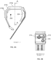
- Figures 4A and 4B are side and perspective views, respectively, of the device of Figure 2 in accordance with some embodiments of the present invention.
- the portions 210a, 210b, and 210c of the casing of device 200 are illustrated from the side.
- the virtual center point of the distal end of a wearer's ulna bone is illustrated schematically as point 222.
- Viewing device 200 in the direction indicated by section A-A in Figure 4A produces the view illustrated in Figure 4B .
- the light source(s) 212 and sensor(s) 214 and/or 216 are shown generally from the point of view of a wearer's wrist.
- each of 212, 214, and 216 has a different axis resulting from the manner in which each of them is angled generally toward the virtual center point 222 of the distal end of a wearer's ulna bone.
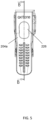
- Figure 5 is another side view of the device of Figure 2 in accordance with some embodiments of the present invention.
- Figure 5 shows, for example, wrist strap 204a of device 200 and opening 226 through which emergency medicine (e.g., one or more pills) may be inserted to and accessed from an at least partially hollow portion of projection 208.
- Emergency medicine e.g., one or more pills
- Viewing device 200 in the direction indicated by section B-B in Figure 5 produces the view illustrated in Figure 4A .
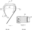
- Figures 6A, 6B , and 6C are an additional side view, and two perspective views, respectively, of the device of Figure 2 in accordance with some embodiments of the present invention.
- Viewing device 200 in the direction indicated by section C-C in Figure 6A produces the view illustrated in Figure 6B .
- device 200 may include one or more projections 602 (e.g., rounded projections) that function, for example, to increase the wearer's comfort and fit of the device to the wearer's wrist.
- Projections 602 may be formed entirely from or otherwise include a flexible and/or stretchable material, such as rubber, silicon, soft plastic, or cloth or any combination thereof for providing the user a comfortable fit and feeling while wearing the device 200.
- projections 602 may be formed entirely from or otherwise include an elastomer material (e.g., silicon) having a softness (durometer) of between 30 to 75 Shore A (e.g., approximately 50 Shore A), which may be the same material that is used for projection 208 and/or pad 220.
- elastomer material e.g., silicon
- durometer softness
- projections 602 may be formed entirely from or otherwise include aluminum and/or thermoplastic urethane (TPU) having a durometer of, for example, between 25 Shore A and 35 Shore A (e.g., approximately 30 Shore A), which may be the same material as the casing (210a, 210b, 210c).
- TPU thermoplastic urethane
- projections 602 may be formed integrally with the casing (210a, 210b, 210c).
- Figure 6C illustrates additional details regarding light source(s) 212 and sensor(s) 214 and/or 216 according to some embodiments of the present invention.
- Viewing device 200 in the direction indicated by section D-D in Figure 6A produces the view illustrated in Figure 6C .
- the center points between light source(s) 212 and detector 216 may be approximately 11.3 millimeters (mm) apart. In other embodiments, they may be between about 7 to 15 mm apart, or about 8 to 13 mm apart.
- a distance between a center point of light source(s) 212 and an outer ring of light source(s) 212 may be between 1 and 8 mm, or between 1 and 4 mm (e.g., approximately 3.1 mm apart).
- the center points between light source(s) 212 and detector 214 may be approximately 13.6 millimeters (mm) apart. In other embodiments, they may be between about 9 to 17 mm apart, or about 10 to 14 mm apart.
- projection 218 may have a virtual circumference equal to about 19 mm, which may be generally sufficient to encompass at least parts of light source(s) 12 and/or detector 214. In other embodiments, a virtual circumference of projection 218 may be about 15 to 24 mm and may depend (e.g., be selected based on), for example, on the size of the distal end of the ulna bone of the wearer.
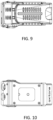
- FIGS 7 and 8 are additional perspective views of the device of Figure 2 in accordance with some embodiments of the present invention.
- Figure 9 is a bottom view of the pulse oximeter of Figure 2 in accordance with some embodiments of the present invention.
- Figure 10 is a top view of the pulse oximeter of Figure 2 in accordance with some embodiments of the present invention.
- Figure 11 is another side view of the pulse oximeter of Figure 2 in accordance with some embodiments of the present invention.
- the outermost part of the device casing is in phantom view to further illustrate the positioning of light source(s) 212, detector 214, and detector 216.
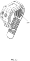
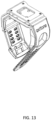
- Figures 12 and 13 are additional perspective views of the pulse oximeter of Figure 2 in accordance with some embodiments of the present invention.
- the outermost part of the device casing and the display 202 are in phantom view to further illustrate the positioning of light source(s) 212, detector 214, and detector 216.
- Figure 14 is an exploded view showing various components of the pulse oximeter of Figure 2 in accordance with some embodiments of the present invention.
- the casing (referenced above as 210a, 210b, and 210c) may include a first component 1402, second component 1404, and third component 1406.
- First component 1402 may be fixed to second component 1404 using one or more screws 1408 or other fixating devices.
- third component 1406 e.g., formed from an elastomer, for example, the same material as projection 208 may be glued or otherwise affixed to second component 1406.
- Component 1410 may include various elements for housing light source(s) 212, detector 214, and detector 216, where these elements of component 1410 that fit through corresponding openings in at least components 1404 and 1406.
- Component 1410 may be encased on its other side by component 1402.
- Figure 15 is a block circuit diagram illustrating hardware functionality of the pulse oximeter of Figure 2 in accordance with some embodiments of the present invention.
- device 200 operates to generate red and infrared optic signals, which are used for heart rate and SPO2 measurements.
- device 200 is capable of detection and measuring of incoming optic signals, movements detection, temperature sensing, signal processing, wireless transmission and receipt of data, visual display of at least heart rate, SPO2 and battery charge status, haptic alerts, battery operation, and power and battery management.
- Figure 15 includes the following nine building blocks: analog front end (AFE) 1502, microcontroller unit (MCU) 1504, alerts transducers (haptic) 1506, sensors (e.g., accelerometer, skin temperature and touch) 1508, PPG sensors (e.g., LEDs and photo-diodes) 1510, display panel 1512, and wireless radio 1514 (e.g., Bluetooth), and power management circuit 1516.
- AFE analog front end
- MCU microcontroller unit
- haptic haptic
- sensors e.g., accelerometer, skin temperature and touch
- PPG sensors e.g., LEDs and photo-diodes
- display panel 1512 e.g., and wireless radio 1514
- wireless radio 1514 e.g., Bluetooth
- AFE block 1502 may be a fully-integrated analog front-end (AFE) suited for pulse oximeter applications. It may include a low-noise receiver channel with an integrated analog-to-digital converter (ADC), an LED transmit section, and diagnostics for sensor and LED fault detection. AFE block 1502 may be a configurable timing controller. This flexibility may enable the user to control the device timing characteristics. To ease clocking requirements and provide a low-jitter clock, an oscillator may also be integrated that functions from an external crystal. The AFE block 1502 may communicate to an external microcontroller or host processor using a suitable interface, such as, for example, an SPI TM interface.
- AFE analog front-end
- the MCU block 1504 may be in charge of all the control and housekeeping tasks of device 200 as well as the SPO2 and heart rate signal processing and calculations.
- the MCU block 1504 may store and be configured to run one or more computer programs and/or applications.
- the computer instructions for such programs and/or applications may be stored in one or more non-transitory computer readable media of MCU block 1504.
- the alerts transducers 1506 may contain one or more haptic transducers that provide haptic alerts whenever a fault is encountered or the wearer's SPO2 level goes below a certain level.
- Sensors 1508 may include some or all of the following sensors: (i) accelerometer and gyroscope to provides movements and position data; (ii) skin temperature sensor to provide skin temperature data; and (iii) a touch sensor to detect if the device is attached to a wearer's wrist or not.
- Display 1512 may be an OLED display (e.g., 96 x 96 pixels), and may display the calculated SPO2 and heart-rate as well as one or more status symbols and error messages.
- OLED display e.g., 96 x 96 pixels
- Wireless radio 1514 may implement one or more suitable wireless communication functionalit(ies) (e.g., Bluetooth 4 (BLE) standard) and may be used to establish one or more communication channels between device 200 and, for example, a dedicated control and monitoring application (e.g., running on the wearer's mobile device such as a mobile phone) and/or a remote monitoring facility accessed via the internet or a cellular communications network.
- suitable wireless communication functionalit(ies) e.g., Bluetooth 4 (BLE) standard
- BLE Bluetooth 4
- a dedicated control and monitoring application e.g., running on the wearer's mobile device such as a mobile phone
- a remote monitoring facility accessed via the internet or a cellular communications network.
- Power and battery management block 1516 may accept a suitable battery (e.g., lithium-ion polymer battery), produce all necessary voltages, charge the battery, and monitor the battery condition.
- a suitable battery e.g., lithium-ion polymer battery
- SPO2 pulse oximetry data
- Sa02 reference functional arterial oxygen saturation
- PR pulse rate
- HR reference heart rate
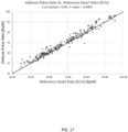
- Figure 18 is a graph of PPG signal quality by a pulse oximeter, for each of red and infrared light sources, in accordance with a device according to Figure 2 in some embodiments of the present invention.
- the y-axis reflects the ratio of the alternating current (AC) to direct current (DC) portion of the signal, and the x-axis is time in seconds.
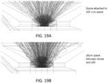
- Figures 19A, 19B , 20A, 20B , 21A, and 21B illustrate embodiments of light source configurations for a wrist-worn pulse oximeter (e.g., configurations for light source(s) 212 of device 200 in Figure 2 ) according to some embodiments of the present invention.
- Figures 19A and 19B illustrate the light that passes through a dome-shaped lens (e.g., 4 or 5 mm dome-shaped lens) that is attached to a light emitting diode (LED) without space ( Figure 19A ) or with a 10 micrometer space between them ( Figure 19B ).
- the light rays are more concentrated when there is a space between the lens and the LED. Stray light is more prevalent when there is no space between the lens and LED.
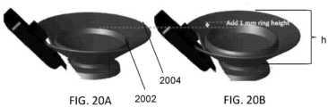
- Figures 20A and 20B illustrate configurations for a housing for light source(s) according to some embodiments of the present invention.
- the housing includes a raised inner ring 2002 and an outer ring 2004.
- the light source(s) e.g., one or more LEDs housed by the structure shown in Figures 20A and 20B may be placed generally within the area encompassed by inner ring 2002.
- the light source(s) may be positioned below, equal to, or above the height of inner ring 2002.
- inner ring 2002 may have a height that is greater than zero but less than or equal to the height (h) of outer ring 2004.
- the height of the outer ring 2004 may be between about 1 millimeter (mm) (or less), to about 15 mm (e.g., approximately 4 mm).
- the height of the inner ring 2002 may be between about 1 millimeter (mm) (or less) to about 15 mm (e.g., approximately 2 mm).
- locating the base of inner ring 2002 at half the height of outer ring 2004 may reduce stray light by approximately 40%.
- the housing contains an inner ring 2002 but no outer ring 2004.
- inner ring 2002 may have a height of zero (i.e., no inner ring), in which case the light source(s) housed by the structure may be placed generally within the area encompassed by outer ring 2004, and may be positioned in various embodiments below, equal to, or above the height of outer ring 2004.
- a housing is provided that does not contain inner ring 2002 nor outer ring 2004.
- Figures 21A and 21B each illustrate a configuration for a housing for light source(s) according to some embodiments of the present invention. They may be the same as or similar to the housing(s) shown in Figures 20A and 20B , respectively, albeit in side view. As shown, in both the Figure 21A and 21B embodiments the housing is generally conically-shaped and extends at an angle. When the angle was increased from about 56.5 degrees to about 59 degrees (an increase of about 2.5 degrees), stray light from the light source decreased by about 80%. In other embodiments, the housing may be at least partially cylindrically-shaped.
- a maximal diameter of the housing (measured at the top of the housing at the outer ring) may be in a range of about 1 mm (or less) to about 30 mm, or from about 5 mm to about 20 mm (e.g., about 14 mm and making an angle of about 60 degrees).
- the housing may cover adjacent detector(s) as well (e.g., but leaving an opening over the detector(s) as partially shown in Figures 21A and 21B ).
- a diameter of the inner ring may be about 1 mm (or less) to about 25 mm, or from about 5 mm to about 20 mm (e.g., about 8 mm).
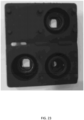
- FIGs 22 and 23 illustrate housings for light source(s) and detector(s) according to some embodiments of the present invention.
- These housings may be embodiments of component 1410 ( Figure 14 ), where the housings for the light source(s) and detector(s) are at least partially cylindrically-shaped.
- a front side of this component which may be an insert for inclusion within a device (e.g., device 200), where light is emitted from is shown in Figure 22 .
- a rear side of this component is shown in Figure 23 .
- such housings may have the general dimensions (e.g., in terms of height(s) and diameter(s)) described above in connection with Figures 20A, 20B , 21A, and 21B .
- the inner and outer rings of the housings form a spring-like configuration (e.g., resulting from their collective configuration like a garmoshka and/or in other embodiments based on the inclusion of one or more springs).
- the housings may be elastic, flexible, and spring-like for fixation to a wearer and/or to function as a damper to movement (artifacts) and to direct an optical axis of corresponding optical elements towards point 222 to maintain a transillumination and/or reflection configuration.
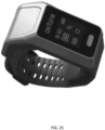
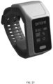
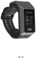
- Figures 24 through 29 illustrate multiple views of a device (e.g., wrist-type pulse oximeter) in accordance with another embodiment of the present invention.
- the device may measure and/or display data regarding SPO2, pulse rate, Bluetooth status, notification (envelope icon) and battery charge level.
- an opening 2602 e.g., the same as or similar to opening 226) for receipt or access of emergency medication (e.g., one or more pills) may be provided.
- the device shown in Figures 24 through 29 may be the same as or similar to device 200 ( Figure 2 ) in all other respects.
- a method of oximetry measurement includes fixating a device at an area above a distal end of the ulna. This may be carried out, for example, through the use of projection 218, projection 208, and/or one or more dome-shaped projections of light source(s) 212, detector 214, and/or detector 216. Thereafter, one or more detectors at, adjacent to, or at a periphery of the fixated area may detect reflections of light by the distal end of the ulna, wherein the light was emitted by one or more (e.g., at least two) light sources having different wave lengths at, adjacent to, or at a periphery of the fixated area.
- one or more (e.g., at least two) light sources having different wave lengths at, adjacent to, or at a periphery of the fixated area.
- the detecting and emitting may be performed by detector(s) 214 and/or 216, and one or more emitter(s) 212, each having a different axis resulting from the manner in which each of them is angled generally toward a virtual center point 222 of the distal end of a wearer's ulna bone.
- the method may further include blocking stray light from entering the fixated area, for example, by one or more projections 220.
- the method may further comprise measuring a pulse by reflecting a coherent light source off a bone.
Landscapes
- Health & Medical Sciences (AREA)
- Life Sciences & Earth Sciences (AREA)
- Physics & Mathematics (AREA)
- Surgery (AREA)
- General Health & Medical Sciences (AREA)
- Engineering & Computer Science (AREA)
- Biomedical Technology (AREA)
- Heart & Thoracic Surgery (AREA)
- Medical Informatics (AREA)
- Molecular Biology (AREA)
- Biophysics (AREA)
- Animal Behavior & Ethology (AREA)
- Pathology (AREA)
- Public Health (AREA)
- Veterinary Medicine (AREA)
- Cardiology (AREA)
- Spectroscopy & Molecular Physics (AREA)
- Optics & Photonics (AREA)
- Physiology (AREA)
- Measuring Pulse, Heart Rate, Blood Pressure Or Blood Flow (AREA)
- Measurement Of The Respiration, Hearing Ability, Form, And Blood Characteristics Of Living Organisms (AREA)
Claims (9)
- Dispositif d'oxymétrie de pouls (200), le dispositif comprenant :au moins deux sources de lumière (212) présentant des longueurs d'onde différentes ;au moins un détecteur (214, 216) sensible auxdites différentes longueurs d'onde ;un bracelet (204) ; etun boîtier (210) couplé au bracelet pour loger les au moins deux sources de lumière et le au moins un détecteur ;dans lequel chacun des au moins deux sources de lumière (212) et du au moins un détecteur (214, 216) est incliné généralement vers un point central virtuel (222) de l'extrémité distale de l'os cubitus d'un porteur et chacun des au moins deux sources de lumière (212) et du au moins un détecteur (214, 216) présente un axe différent,dans lequel le bracelet (204) comprend :une première partie comprenant une saillie généralement concave (208) adaptée pour s'ajuster parfaitement contre le poignet ru porteur, dans lequel la saillie généralement concave (208) comprend en outre une partie adaptée pour faire face au poignet du porteur, et dans lequel la partie adaptée pour faire face au poignet du porteur comprend en outre une ou plusieurs crêtes (224) ; etune seconde partie adaptée pour la fixation à la première partie pour fixer le bracelet (204) autour du poignet d'un porteur, dans lequel la seconde partie comprend une seconde saillie (218) qui aide à fixer le dispositif au niveau d'une zone fixée correspondant à une extrémité distale de l'os cubitus du porteur.
- Dispositif d'oxymétrie de pouls (200) selon la revendication 1, dans lequel chacun des au moins deux sources de lumière (212) et du au moins un détecteur (214, 216) est positionné à l'intérieur du boîtier (210) de telle sorte que, lorsque le bracelet (204) est fixé autour du poignet du porteur, les au moins deux sources de lumière (212) et le au moins un détecteur (214, 216) soient positionnés adjacents à l'extrémité distale du cubitus et plus près du cubitus que du radius, et le au moins un détecteur (214, 216) soit positionné pour détecter de la lumière émise par les au moins deux sources de lumière (212).
- Dispositif d'oxymétrie de pouls (200) selon une quelconque revendication précédente, dans lequel au moins l'un des au moins deux sources de lumière (212) et du au moins un détecteur (214, 216) comprend une structure généralement en forme de dôme ou de forme conique qui aide à fixer le dispositif d'oxymétrie de pouls, et ses au moins deux sources de lumière correspondantes (212) et son au moins un détecteur (214, 216), au niveau de la zone fixée correspondant à l'extrémité distale de l'os cubitus du porteur.
- Dispositif d'oxymétrie de pouls (200) selon l'une quelconque des revendications précédentes, comprenant en outre un coussinet qui est monté ou, sinon, généralement sur un côté intérieur du boîtier (210), dans lequel ledit coussinet comprend une ou plusieurs barrières qui fonctionnent pour s'ajuster parfaitement contre le poignet d'un porteur et empêcher une lumière parasite de pénétrer dans une zone de mesure des au moins deux sources de lumière (212) et du au moins un détecteur (214, 216) lorsque le dispositif d'oxymétrie de pouls est porté par un porteur.
- Dispositif d'oxymétrie de pouls (200) selon l'une quelconque des revendications précédentes, dans lequel lesdites au moins deux sources de lumière (212) et ledit au moins un détecteur de lumière sont disposés les uns par rapport aux autres de telle sorte que ladite lumière émise soit adaptée pour trans-illuminer via le cubitus avant d'atteindre ledit au moins un détecteur de lumière.
- Dispositif d'oxymétrie de pouls (200) selon l'une quelconque des revendications précédentes, dans lequel ledit au moins un détecteur (214, 216) est adapté pour mesurer une trans-illumination à un angle compris entre environ 20° et 160° par rapport à un trajet incident de ladite lumière émise.
- Dispositif d'oxymétrie de pouls (200) selon l'une quelconque des revendications précédentes, dans lequel ledit au moins un détecteur (214, 216) est adapté pour mesurer une trans-illumination à un angle compris entre environ 70° et 110° par rapport à un trajet incident de ladite lumière émise.
- Dispositif d'oxymétrie de pouls (200) selon l'une quelconque des revendications précédentes, dans lequel les au moins deux sources de lumière (212) sont des composants sélectionnés dans le groupe constitué par : des DEL présentant différentes plages de longueurs d'onde, des diodes laser présentant différentes longueurs d'onde, et une combinaison de DEL et de diodes laser présentant des longueurs d'onde en dehors de la plage desdites DEL.
- Dispositif d'oxymétrie de pouls (200) selon l'une quelconque des revendications précédentes, comprenant en outre au moins un processeur configuré pour calculer des données d'oxymétrie à partir d'une lumière détectée par ledit au moins un détecteur (214, 216).
Applications Claiming Priority (2)
| Application Number | Priority Date | Filing Date | Title |
|---|---|---|---|
| US201662438501P | 2016-12-23 | 2016-12-23 | |
| PCT/IB2017/058022 WO2018116110A1 (fr) | 2016-12-23 | 2017-12-15 | Dispositif et procédé d'oxymétrie de pouls à capteur de poignet |
Publications (2)
| Publication Number | Publication Date |
|---|---|
| EP3558096A1 EP3558096A1 (fr) | 2019-10-30 |
| EP3558096B1 true EP3558096B1 (fr) | 2025-01-22 |
Family
ID=60972265
Family Applications (1)
| Application Number | Title | Priority Date | Filing Date |
|---|---|---|---|
| EP17829296.7A Active EP3558096B1 (fr) | 2016-12-23 | 2017-12-15 | Dispositif d'oxymétrie de pouls à capteur de poignet |
Country Status (6)
| Country | Link |
|---|---|
| US (1) | US11241177B2 (fr) |
| EP (1) | EP3558096B1 (fr) |
| CN (1) | CN110300545B (fr) |
| CA (1) | CA3047929A1 (fr) |
| IL (1) | IL267467B2 (fr) |
| WO (1) | WO2018116110A1 (fr) |
Families Citing this family (10)
| Publication number | Priority date | Publication date | Assignee | Title |
|---|---|---|---|---|
| GB2572626B (en) * | 2018-04-05 | 2021-04-07 | Life Meter Srl | Pulse oximetry device, system and method |
| USD912830S1 (en) * | 2018-06-18 | 2021-03-09 | Oxitone Medical Ltd. | Sensors case for watch |
| KR102062259B1 (ko) * | 2018-12-18 | 2020-01-03 | 에이아이몬 주식회사 | 신체 부착형 생체신호 획득 장치 |
| JP7237574B2 (ja) * | 2018-12-27 | 2023-03-13 | オムロンヘルスケア株式会社 | 血圧測定装置 |
| EP4167830A4 (fr) * | 2019-05-05 | 2024-10-23 | Rehn, Annabelle | Bande intelligente pour alerter en cas d'urgence |
| US10813578B1 (en) | 2019-12-26 | 2020-10-27 | Biobeat Technologies Ltd. | Sensor device for optical measurement of biological properties |
| CN111642867A (zh) * | 2020-06-08 | 2020-09-11 | 深圳迈拓数码科技有限公司 | 一种具有生命体征监测的智能手表 |
| CN114468989B (zh) * | 2021-02-11 | 2022-11-25 | 先阳科技有限公司 | 组织成分测量方法、装置及可穿戴设备 |
| CN114468992B (zh) * | 2021-02-11 | 2023-02-24 | 先阳科技有限公司 | 组织成分测量方法、装置及可穿戴设备 |
| KR20240052769A (ko) | 2021-08-09 | 2024-04-23 | 제이매드 크리에이션즈 엘엘씨 | 비-멜라닌-편향된 펄스 옥시미터 및 동반된 환자 모니터링 기술 |
Citations (3)
| Publication number | Priority date | Publication date | Assignee | Title |
|---|---|---|---|---|
| US6443906B1 (en) * | 2000-10-09 | 2002-09-03 | Healthstats International Pte Ltd. | Method and device for monitoring blood pressure |
| US20140200423A1 (en) * | 2011-08-30 | 2014-07-17 | Oxitone Medical Ltd. | Wearable pulse oximetry device |
| US20140275852A1 (en) * | 2012-06-22 | 2014-09-18 | Fitbit, Inc. | Wearable heart rate monitor |
Family Cites Families (13)
| Publication number | Priority date | Publication date | Assignee | Title |
|---|---|---|---|---|
| EP2285275B1 (fr) * | 2008-05-14 | 2019-04-24 | HeartMiles, LLC | Dispositif de surveillance d'activité physique et unité de collecte de données |
| US20100168531A1 (en) * | 2008-10-22 | 2010-07-01 | Dr. Phillip Andrew Shaltis | Rapidly deployable sensor design for enhanced noninvasive vital sign monitoring |
| US8515515B2 (en) | 2009-03-25 | 2013-08-20 | Covidien Lp | Medical sensor with compressible light barrier and technique for using the same |
| US8868149B2 (en) | 2009-07-30 | 2014-10-21 | Oxitone Medical Ltd. | Photoplethysmography device and method |
| JP5454147B2 (ja) | 2010-01-05 | 2014-03-26 | セイコーエプソン株式会社 | 生体情報検出器及び生体情報測定装置 |
| US20130206801A1 (en) * | 2012-02-09 | 2013-08-15 | Grant Delgatty | Portable elastic pill container |
| US20140117060A1 (en) * | 2012-10-25 | 2014-05-01 | Michael Colone | Wearable medical storage device |
| US20140171766A1 (en) | 2012-12-13 | 2014-06-19 | Spot Check Medical Ltd. Co., A New Mexico Llc | Oximetry sensor adjunct for routine diagnostic screening and monitoring |
| GB2517178B (en) * | 2013-08-14 | 2015-12-09 | Vallipuram Balendran Partheban | Ergonomic wristband with device support means |
| CN204306810U (zh) * | 2014-12-05 | 2015-05-06 | 四川省人民医院 | 一种腕戴式脉搏与血压监测装置 |
| US10076254B2 (en) * | 2014-12-16 | 2018-09-18 | Microsoft Technology Licensing, Llc | Optical communication with optical sensors |
| DE102015106869A1 (de) * | 2015-05-04 | 2016-11-10 | Alexander Hirt | Uhr mit Container und Verfahren zu ihrer Verwendung |
| CN105919602B (zh) | 2016-05-26 | 2018-08-24 | 成都云卫康医疗科技有限公司 | 能自动贴附皮肤的腕式无附件血氧测量设备及其制造方法 |
-
2017
- 2017-12-15 WO PCT/IB2017/058022 patent/WO2018116110A1/fr not_active Ceased
- 2017-12-15 EP EP17829296.7A patent/EP3558096B1/fr active Active
- 2017-12-15 IL IL267467A patent/IL267467B2/en unknown
- 2017-12-15 CN CN201780087332.XA patent/CN110300545B/zh active Active
- 2017-12-15 US US16/468,045 patent/US11241177B2/en active Active
- 2017-12-15 CA CA3047929A patent/CA3047929A1/fr active Pending
Patent Citations (3)
| Publication number | Priority date | Publication date | Assignee | Title |
|---|---|---|---|---|
| US6443906B1 (en) * | 2000-10-09 | 2002-09-03 | Healthstats International Pte Ltd. | Method and device for monitoring blood pressure |
| US20140200423A1 (en) * | 2011-08-30 | 2014-07-17 | Oxitone Medical Ltd. | Wearable pulse oximetry device |
| US20140275852A1 (en) * | 2012-06-22 | 2014-09-18 | Fitbit, Inc. | Wearable heart rate monitor |
Also Published As
| Publication number | Publication date |
|---|---|
| IL267467B2 (en) | 2024-01-01 |
| IL267467B1 (en) | 2023-09-01 |
| IL267467A (en) | 2019-08-29 |
| CN110300545A (zh) | 2019-10-01 |
| CN110300545B (zh) | 2023-10-27 |
| WO2018116110A1 (fr) | 2018-06-28 |
| US11241177B2 (en) | 2022-02-08 |
| US20200015723A1 (en) | 2020-01-16 |
| CA3047929A1 (fr) | 2018-06-28 |
| EP3558096A1 (fr) | 2019-10-30 |
Similar Documents
| Publication | Publication Date | Title |
|---|---|---|
| EP3558096B1 (fr) | Dispositif d'oxymétrie de pouls à capteur de poignet | |
| US12336796B2 (en) | Wearable device with physiological parameters monitoring | |
| EP4248847B1 (fr) | Dispositif portatif avec surveillance de paramètre physiologique | |
| US11998304B2 (en) | Ring for optically measuring biometric data | |
| US12495999B2 (en) | Wearable band for health monitoring device | |
| EP3148363B1 (fr) | Sangle de moniteur biométrique | |
| WO2007011423A1 (fr) | Capteur de timbre transdermique permettant de mesurer la pression sanguine sans ballonnet | |
| US12478293B1 (en) | Systems and methods for assessment of placement of a detector of a physiological monitoring device | |
| HK40058446A (en) | Wearable device with physiological parameters monitoring | |
| HK40058446B (en) | Wearable device with physiological parameters monitoring | |
| US20220378308A1 (en) | Method And Device That Monitors A Fetal Heart Rate | |
| CN118019489A (zh) | 具有生理参数监视的可穿戴设备 | |
| HK1234616B (en) | Biometric monitor strap | |
| HK1234616A1 (en) | Biometric monitor strap |
Legal Events
| Date | Code | Title | Description |
|---|---|---|---|
| STAA | Information on the status of an ep patent application or granted ep patent |
Free format text: STATUS: UNKNOWN |
|
| STAA | Information on the status of an ep patent application or granted ep patent |
Free format text: STATUS: THE INTERNATIONAL PUBLICATION HAS BEEN MADE |
|
| PUAI | Public reference made under article 153(3) epc to a published international application that has entered the european phase |
Free format text: ORIGINAL CODE: 0009012 |
|
| STAA | Information on the status of an ep patent application or granted ep patent |
Free format text: STATUS: REQUEST FOR EXAMINATION WAS MADE |
|
| 17P | Request for examination filed |
Effective date: 20190715 |
|
| AK | Designated contracting states |
Kind code of ref document: A1 Designated state(s): AL AT BE BG CH CY CZ DE DK EE ES FI FR GB GR HR HU IE IS IT LI LT LU LV MC MK MT NL NO PL PT RO RS SE SI SK SM TR |
|
| AX | Request for extension of the european patent |
Extension state: BA ME |
|
| DAV | Request for validation of the european patent (deleted) | ||
| DAX | Request for extension of the european patent (deleted) | ||
| PUAG | Search results despatched under rule 164(2) epc together with communication from examining division |
Free format text: ORIGINAL CODE: 0009017 |
|
| STAA | Information on the status of an ep patent application or granted ep patent |
Free format text: STATUS: EXAMINATION IS IN PROGRESS |
|
| 17Q | First examination report despatched |
Effective date: 20210607 |
|
| B565 | Issuance of search results under rule 164(2) epc |
Effective date: 20210607 |
|
| RIC1 | Information provided on ipc code assigned before grant |
Ipc: A61B 5/00 20060101AFI20210601BHEP Ipc: A61B 5/024 20060101ALI20210601BHEP Ipc: A61B 5/1455 20060101ALI20210601BHEP |
|
| GRAP | Despatch of communication of intention to grant a patent |
Free format text: ORIGINAL CODE: EPIDOSNIGR1 |
|
| STAA | Information on the status of an ep patent application or granted ep patent |
Free format text: STATUS: GRANT OF PATENT IS INTENDED |
|
| INTG | Intention to grant announced |
Effective date: 20240821 |
|
| GRAS | Grant fee paid |
Free format text: ORIGINAL CODE: EPIDOSNIGR3 |
|
| GRAA | (expected) grant |
Free format text: ORIGINAL CODE: 0009210 |
|
| STAA | Information on the status of an ep patent application or granted ep patent |
Free format text: STATUS: THE PATENT HAS BEEN GRANTED |
|
| RIN1 | Information on inventor provided before grant (corrected) |
Inventor name: SHAHAM, AVI Inventor name: HARPAK, OFER Inventor name: GIL, KOBY REFAEL Inventor name: BEN-ZION, UZI Inventor name: EISEN, LEON |
|
| AK | Designated contracting states |
Kind code of ref document: B1 Designated state(s): AL AT BE BG CH CY CZ DE DK EE ES FI FR GB GR HR HU IE IS IT LI LT LU LV MC MK MT NL NO PL PT RO RS SE SI SK SM TR |
|
| REG | Reference to a national code |
Ref country code: GB Ref legal event code: FG4D |
|
| REG | Reference to a national code |
Ref country code: CH Ref legal event code: EP |
|
| REG | Reference to a national code |
Ref country code: IE Ref legal event code: FG4D |
|
| REG | Reference to a national code |
Ref country code: DE Ref legal event code: R096 Ref document number: 602017087466 Country of ref document: DE |
|
| REG | Reference to a national code |
Ref country code: NL Ref legal event code: FP |
|
| PG25 | Lapsed in a contracting state [announced via postgrant information from national office to epo] |
Ref country code: RS Free format text: LAPSE BECAUSE OF FAILURE TO SUBMIT A TRANSLATION OF THE DESCRIPTION OR TO PAY THE FEE WITHIN THE PRESCRIBED TIME-LIMIT Effective date: 20250422 |
|
| PG25 | Lapsed in a contracting state [announced via postgrant information from national office to epo] |
Ref country code: FI Free format text: LAPSE BECAUSE OF FAILURE TO SUBMIT A TRANSLATION OF THE DESCRIPTION OR TO PAY THE FEE WITHIN THE PRESCRIBED TIME-LIMIT Effective date: 20250122 |
|
| PG25 | Lapsed in a contracting state [announced via postgrant information from national office to epo] |
Ref country code: PL Free format text: LAPSE BECAUSE OF FAILURE TO SUBMIT A TRANSLATION OF THE DESCRIPTION OR TO PAY THE FEE WITHIN THE PRESCRIBED TIME-LIMIT Effective date: 20250122 |
|
| PG25 | Lapsed in a contracting state [announced via postgrant information from national office to epo] |
Ref country code: ES Free format text: LAPSE BECAUSE OF FAILURE TO SUBMIT A TRANSLATION OF THE DESCRIPTION OR TO PAY THE FEE WITHIN THE PRESCRIBED TIME-LIMIT Effective date: 20250122 |
|
| REG | Reference to a national code |
Ref country code: LT Ref legal event code: MG9D |
|
| PG25 | Lapsed in a contracting state [announced via postgrant information from national office to epo] |
Ref country code: IS Free format text: LAPSE BECAUSE OF FAILURE TO SUBMIT A TRANSLATION OF THE DESCRIPTION OR TO PAY THE FEE WITHIN THE PRESCRIBED TIME-LIMIT Effective date: 20250522 Ref country code: NO Free format text: LAPSE BECAUSE OF FAILURE TO SUBMIT A TRANSLATION OF THE DESCRIPTION OR TO PAY THE FEE WITHIN THE PRESCRIBED TIME-LIMIT Effective date: 20250422 |
|
| REG | Reference to a national code |
Ref country code: AT Ref legal event code: MK05 Ref document number: 1760800 Country of ref document: AT Kind code of ref document: T Effective date: 20250122 |
|
| PG25 | Lapsed in a contracting state [announced via postgrant information from national office to epo] |
Ref country code: HR Free format text: LAPSE BECAUSE OF FAILURE TO SUBMIT A TRANSLATION OF THE DESCRIPTION OR TO PAY THE FEE WITHIN THE PRESCRIBED TIME-LIMIT Effective date: 20250122 |
|
| PG25 | Lapsed in a contracting state [announced via postgrant information from national office to epo] |
Ref country code: LV Free format text: LAPSE BECAUSE OF FAILURE TO SUBMIT A TRANSLATION OF THE DESCRIPTION OR TO PAY THE FEE WITHIN THE PRESCRIBED TIME-LIMIT Effective date: 20250122 Ref country code: PT Free format text: LAPSE BECAUSE OF FAILURE TO SUBMIT A TRANSLATION OF THE DESCRIPTION OR TO PAY THE FEE WITHIN THE PRESCRIBED TIME-LIMIT Effective date: 20250522 |
|
| PG25 | Lapsed in a contracting state [announced via postgrant information from national office to epo] |
Ref country code: GR Free format text: LAPSE BECAUSE OF FAILURE TO SUBMIT A TRANSLATION OF THE DESCRIPTION OR TO PAY THE FEE WITHIN THE PRESCRIBED TIME-LIMIT Effective date: 20250423 Ref country code: BG Free format text: LAPSE BECAUSE OF FAILURE TO SUBMIT A TRANSLATION OF THE DESCRIPTION OR TO PAY THE FEE WITHIN THE PRESCRIBED TIME-LIMIT Effective date: 20250122 |
|
| PG25 | Lapsed in a contracting state [announced via postgrant information from national office to epo] |
Ref country code: AT Free format text: LAPSE BECAUSE OF FAILURE TO SUBMIT A TRANSLATION OF THE DESCRIPTION OR TO PAY THE FEE WITHIN THE PRESCRIBED TIME-LIMIT Effective date: 20250122 |
|
| PG25 | Lapsed in a contracting state [announced via postgrant information from national office to epo] |
Ref country code: SE Free format text: LAPSE BECAUSE OF FAILURE TO SUBMIT A TRANSLATION OF THE DESCRIPTION OR TO PAY THE FEE WITHIN THE PRESCRIBED TIME-LIMIT Effective date: 20250122 |
|
| PG25 | Lapsed in a contracting state [announced via postgrant information from national office to epo] |
Ref country code: SM Free format text: LAPSE BECAUSE OF FAILURE TO SUBMIT A TRANSLATION OF THE DESCRIPTION OR TO PAY THE FEE WITHIN THE PRESCRIBED TIME-LIMIT Effective date: 20250122 |
|
| PG25 | Lapsed in a contracting state [announced via postgrant information from national office to epo] |
Ref country code: DK Free format text: LAPSE BECAUSE OF FAILURE TO SUBMIT A TRANSLATION OF THE DESCRIPTION OR TO PAY THE FEE WITHIN THE PRESCRIBED TIME-LIMIT Effective date: 20250122 |
|
| PG25 | Lapsed in a contracting state [announced via postgrant information from national office to epo] |
Ref country code: IT Free format text: LAPSE BECAUSE OF FAILURE TO SUBMIT A TRANSLATION OF THE DESCRIPTION OR TO PAY THE FEE WITHIN THE PRESCRIBED TIME-LIMIT Effective date: 20250122 |
|
| P01 | Opt-out of the competence of the unified patent court (upc) registered |
Free format text: CASE NUMBER: UPC_APP_7406_3558096/2025 Effective date: 20250917 |
|
| PG25 | Lapsed in a contracting state [announced via postgrant information from national office to epo] |
Ref country code: EE Free format text: LAPSE BECAUSE OF FAILURE TO SUBMIT A TRANSLATION OF THE DESCRIPTION OR TO PAY THE FEE WITHIN THE PRESCRIBED TIME-LIMIT Effective date: 20250122 Ref country code: CZ Free format text: LAPSE BECAUSE OF FAILURE TO SUBMIT A TRANSLATION OF THE DESCRIPTION OR TO PAY THE FEE WITHIN THE PRESCRIBED TIME-LIMIT Effective date: 20250122 |
|
| REG | Reference to a national code |
Ref country code: DE Ref legal event code: R097 Ref document number: 602017087466 Country of ref document: DE |
|
| PG25 | Lapsed in a contracting state [announced via postgrant information from national office to epo] |
Ref country code: RO Free format text: LAPSE BECAUSE OF FAILURE TO SUBMIT A TRANSLATION OF THE DESCRIPTION OR TO PAY THE FEE WITHIN THE PRESCRIBED TIME-LIMIT Effective date: 20250122 |
|
| PG25 | Lapsed in a contracting state [announced via postgrant information from national office to epo] |
Ref country code: SK Free format text: LAPSE BECAUSE OF FAILURE TO SUBMIT A TRANSLATION OF THE DESCRIPTION OR TO PAY THE FEE WITHIN THE PRESCRIBED TIME-LIMIT Effective date: 20250122 |
|
| PLBE | No opposition filed within time limit |
Free format text: ORIGINAL CODE: 0009261 |
|
| STAA | Information on the status of an ep patent application or granted ep patent |
Free format text: STATUS: NO OPPOSITION FILED WITHIN TIME LIMIT |
|
| 26N | No opposition filed |
Effective date: 20251023 |