EP3557716A1 - Communication-during-discharge-type portable multi-use power storage device - Google Patents
Communication-during-discharge-type portable multi-use power storage device Download PDFInfo
- Publication number
- EP3557716A1 EP3557716A1 EP18742164.9A EP18742164A EP3557716A1 EP 3557716 A1 EP3557716 A1 EP 3557716A1 EP 18742164 A EP18742164 A EP 18742164A EP 3557716 A1 EP3557716 A1 EP 3557716A1
- Authority
- EP
- European Patent Office
- Prior art keywords
- storage device
- power storage
- main body
- device main
- communication
- Prior art date
- Legal status (The legal status is an assumption and is not a legal conclusion. Google has not performed a legal analysis and makes no representation as to the accuracy of the status listed.)
- Granted
Links
- 238000004891 communication Methods 0.000 claims abstract description 329
- 238000012544 monitoring process Methods 0.000 claims abstract description 172
- 238000007599 discharging Methods 0.000 claims abstract description 50
- 230000001133 acceleration Effects 0.000 claims description 13
- 238000007726 management method Methods 0.000 description 155
- 238000000034 method Methods 0.000 description 34
- 230000008569 process Effects 0.000 description 34
- 238000012545 processing Methods 0.000 description 24
- 230000006870 function Effects 0.000 description 18
- 230000008859 change Effects 0.000 description 12
- 238000012986 modification Methods 0.000 description 12
- 230000004048 modification Effects 0.000 description 12
- 238000004146 energy storage Methods 0.000 description 9
- 239000000470 constituent Substances 0.000 description 7
- 238000013500 data storage Methods 0.000 description 7
- 230000000694 effects Effects 0.000 description 6
- XLYOFNOQVPJJNP-UHFFFAOYSA-N water Substances O XLYOFNOQVPJJNP-UHFFFAOYSA-N 0.000 description 6
- 239000003990 capacitor Substances 0.000 description 4
- 230000008878 coupling Effects 0.000 description 4
- 238000010168 coupling process Methods 0.000 description 4
- 238000005859 coupling reaction Methods 0.000 description 4
- 238000010586 diagram Methods 0.000 description 4
- 238000003384 imaging method Methods 0.000 description 3
- 230000001186 cumulative effect Effects 0.000 description 2
- 238000001514 detection method Methods 0.000 description 2
- 238000007689 inspection Methods 0.000 description 2
- 238000005259 measurement Methods 0.000 description 2
- 241000251468 Actinopterygii Species 0.000 description 1
- 238000007664 blowing Methods 0.000 description 1
- 230000001413 cellular effect Effects 0.000 description 1
- 238000002485 combustion reaction Methods 0.000 description 1
- 238000010276 construction Methods 0.000 description 1
- 238000010411 cooking Methods 0.000 description 1
- 230000006866 deterioration Effects 0.000 description 1
- 238000003745 diagnosis Methods 0.000 description 1
- 238000005516 engineering process Methods 0.000 description 1
- 239000004973 liquid crystal related substance Substances 0.000 description 1
- 230000007774 longterm Effects 0.000 description 1
- 230000007246 mechanism Effects 0.000 description 1
- 238000010295 mobile communication Methods 0.000 description 1
- 230000002123 temporal effect Effects 0.000 description 1
- 238000005406 washing Methods 0.000 description 1
- 238000003466 welding Methods 0.000 description 1
Images


Classifications
-
- B—PERFORMING OPERATIONS; TRANSPORTING
- B60—VEHICLES IN GENERAL
- B60L—PROPULSION OF ELECTRICALLY-PROPELLED VEHICLES; SUPPLYING ELECTRIC POWER FOR AUXILIARY EQUIPMENT OF ELECTRICALLY-PROPELLED VEHICLES; ELECTRODYNAMIC BRAKE SYSTEMS FOR VEHICLES IN GENERAL; MAGNETIC SUSPENSION OR LEVITATION FOR VEHICLES; MONITORING OPERATING VARIABLES OF ELECTRICALLY-PROPELLED VEHICLES; ELECTRIC SAFETY DEVICES FOR ELECTRICALLY-PROPELLED VEHICLES
- B60L53/00—Methods of charging batteries, specially adapted for electric vehicles; Charging stations or on-board charging equipment therefor; Exchange of energy storage elements in electric vehicles
- B60L53/80—Exchanging energy storage elements, e.g. removable batteries
-
- B—PERFORMING OPERATIONS; TRANSPORTING
- B60—VEHICLES IN GENERAL
- B60L—PROPULSION OF ELECTRICALLY-PROPELLED VEHICLES; SUPPLYING ELECTRIC POWER FOR AUXILIARY EQUIPMENT OF ELECTRICALLY-PROPELLED VEHICLES; ELECTRODYNAMIC BRAKE SYSTEMS FOR VEHICLES IN GENERAL; MAGNETIC SUSPENSION OR LEVITATION FOR VEHICLES; MONITORING OPERATING VARIABLES OF ELECTRICALLY-PROPELLED VEHICLES; ELECTRIC SAFETY DEVICES FOR ELECTRICALLY-PROPELLED VEHICLES
- B60L50/00—Electric propulsion with power supplied within the vehicle
- B60L50/50—Electric propulsion with power supplied within the vehicle using propulsion power supplied by batteries or fuel cells
- B60L50/60—Electric propulsion with power supplied within the vehicle using propulsion power supplied by batteries or fuel cells using power supplied by batteries
-
- H—ELECTRICITY
- H01—ELECTRIC ELEMENTS
- H01M—PROCESSES OR MEANS, e.g. BATTERIES, FOR THE DIRECT CONVERSION OF CHEMICAL ENERGY INTO ELECTRICAL ENERGY
- H01M10/00—Secondary cells; Manufacture thereof
- H01M10/42—Methods or arrangements for servicing or maintenance of secondary cells or secondary half-cells
-
- H—ELECTRICITY
- H02—GENERATION; CONVERSION OR DISTRIBUTION OF ELECTRIC POWER
- H02J—CIRCUIT ARRANGEMENTS OR SYSTEMS FOR SUPPLYING OR DISTRIBUTING ELECTRIC POWER; SYSTEMS FOR STORING ELECTRIC ENERGY
- H02J7/00—Circuit arrangements for charging or depolarising batteries or for supplying loads from batteries
-
- Y—GENERAL TAGGING OF NEW TECHNOLOGICAL DEVELOPMENTS; GENERAL TAGGING OF CROSS-SECTIONAL TECHNOLOGIES SPANNING OVER SEVERAL SECTIONS OF THE IPC; TECHNICAL SUBJECTS COVERED BY FORMER USPC CROSS-REFERENCE ART COLLECTIONS [XRACs] AND DIGESTS
- Y02—TECHNOLOGIES OR APPLICATIONS FOR MITIGATION OR ADAPTATION AGAINST CLIMATE CHANGE
- Y02E—REDUCTION OF GREENHOUSE GAS [GHG] EMISSIONS, RELATED TO ENERGY GENERATION, TRANSMISSION OR DISTRIBUTION
- Y02E60/00—Enabling technologies; Technologies with a potential or indirect contribution to GHG emissions mitigation
- Y02E60/10—Energy storage using batteries
-
- Y—GENERAL TAGGING OF NEW TECHNOLOGICAL DEVELOPMENTS; GENERAL TAGGING OF CROSS-SECTIONAL TECHNOLOGIES SPANNING OVER SEVERAL SECTIONS OF THE IPC; TECHNICAL SUBJECTS COVERED BY FORMER USPC CROSS-REFERENCE ART COLLECTIONS [XRACs] AND DIGESTS
- Y02—TECHNOLOGIES OR APPLICATIONS FOR MITIGATION OR ADAPTATION AGAINST CLIMATE CHANGE
- Y02T—CLIMATE CHANGE MITIGATION TECHNOLOGIES RELATED TO TRANSPORTATION
- Y02T10/00—Road transport of goods or passengers
- Y02T10/60—Other road transportation technologies with climate change mitigation effect
- Y02T10/70—Energy storage systems for electromobility, e.g. batteries
-
- Y—GENERAL TAGGING OF NEW TECHNOLOGICAL DEVELOPMENTS; GENERAL TAGGING OF CROSS-SECTIONAL TECHNOLOGIES SPANNING OVER SEVERAL SECTIONS OF THE IPC; TECHNICAL SUBJECTS COVERED BY FORMER USPC CROSS-REFERENCE ART COLLECTIONS [XRACs] AND DIGESTS
- Y02—TECHNOLOGIES OR APPLICATIONS FOR MITIGATION OR ADAPTATION AGAINST CLIMATE CHANGE
- Y02T—CLIMATE CHANGE MITIGATION TECHNOLOGIES RELATED TO TRANSPORTATION
- Y02T10/00—Road transport of goods or passengers
- Y02T10/60—Other road transportation technologies with climate change mitigation effect
- Y02T10/7072—Electromobility specific charging systems or methods for batteries, ultracapacitors, supercapacitors or double-layer capacitors
-
- Y—GENERAL TAGGING OF NEW TECHNOLOGICAL DEVELOPMENTS; GENERAL TAGGING OF CROSS-SECTIONAL TECHNOLOGIES SPANNING OVER SEVERAL SECTIONS OF THE IPC; TECHNICAL SUBJECTS COVERED BY FORMER USPC CROSS-REFERENCE ART COLLECTIONS [XRACs] AND DIGESTS
- Y02—TECHNOLOGIES OR APPLICATIONS FOR MITIGATION OR ADAPTATION AGAINST CLIMATE CHANGE
- Y02T—CLIMATE CHANGE MITIGATION TECHNOLOGIES RELATED TO TRANSPORTATION
- Y02T90/00—Enabling technologies or technologies with a potential or indirect contribution to GHG emissions mitigation
- Y02T90/10—Technologies relating to charging of electric vehicles
- Y02T90/16—Information or communication technologies improving the operation of electric vehicles
Definitions
- the present invention relates to a portable power storage device which is portable.
- a portable power storage device arranged to be attachable and detachable to and from a vehicle is known.
- This portable power storage device is configured to output stored electric power to the vehicle.
- the vehicle consumes the electric power output from the portable power storage device.
- International Publication No. 2013/016545 discloses a portable electric energy storage device.
- the portable electric energy storage device disclosed in this publication includes, for example, a secondary battery, a super capacitor, or an ultracapacitor.
- the portable electric energy storage device includes a battery cell (power storage device main body), a diagnostic data storage system, and a housing.
- the diagnostic data storage system is configured to be able to send and receive information wirelessly.
- the diagnostic data storage system receives diagnostic data sent from the vehicle wirelessly and stores the data.
- the diagnostic data includes information of a state of the portable electric energy storage device.
- the diagnostic data storage system sends stored diagnostic data to this machine.
- the diagnostic data storage system sends stored diagnostic data to the mobile device wirelessly.
- Patent Literature 1 International Publication No. 2013/016545
- the inventors of the subject application tried to find applications of the portable electric energy storage device of the publication above, other than vehicles. As a result of this, it was found that the applications of the portable electric energy storage device of the publication above were limited.
- An object of the present invention is to provide a portable multi-use power storage device which is attachable and detachable to and from an external power consuming device consuming electric power and is applicable to various types of external power consuming devices.
- a portable power storage device When a portable power storage device has a power storage device main body with large electrical capacity such as a secondary battery, a super capacitor, and an ultracapacitor, functions of the portable power storage device can be improved by managing the charge (electric power supply) to the power storage device main body, the discharge (electric power release) from the power storage device main body, the amount of electric power stored in the power storage device main body.
- the inventors of the subject application studied the applications of the portable power storage device recited in, for example, International Publication No. 2013/016545 .
- the functions of the portable power storage device could be improved by changing the management of the power storage device main body in accordance with the application of the portable power storage device.
- the power storage device main body of the same type can be used for different applications. It is instead necessary to set the management of the power storage device main body to be suitable for each application. On this account, the applications of the portable power storage device are limited.
- the inventors of the subject application scrutinized the management of the power storage device main body.
- the inventors have found in regard to the management of the power storage device main body that, while the overall specification of the management is different between applications of the portable power storage device, the viewpoint for the management is more or less the same.
- the inventors of the subject application found that the versatility regarding the management of the power storage device main body could be improved by applying the following technical idea to the portable power storage device.
- the technical idea is such that, while the power storage device main body is discharging to an external power consuming device, a management device integrated with the power storage device main body is configured to be able to send information related to the use environment of the power storage device main body in accordance with the external power consuming device to an external communication device wirelessly and to receive information from the external communication device wirelessly.
- the information from the external communication device may be information generated based on information received by the external communication device.
- the outside information may be information for managing the power storage device main body.
- the portable power storage device is able to acquire, from the external communication device, information for managing the power storage device main body in accordance with the use environment of the power storage device main body.
- the use environment of the power storage device main body may be different depending on the type of the external power consuming device.
- the external communication device and the portable power storage device communicate with each other, communications between the external power consuming device and the portable power storage device are unnecessary.
- the external power consuming device may not include communication means, for this reason.
- the applications of the portable power storage device can therefore be further extended.
- the power storage device main body transmits information related to the use environment of the power storage device main body to the external communication device wirelessly while the power storage device main body is discharging
- the external communication device is able to acquire information of the use environment from each of the portable power storage devices while they are discharging. It is therefore possible to grasp the state and tendency of each of the portable power storage devices. By utilizing the grasped information, for example, the utilization efficiency of the power storage device main body can be improved. The applications of the portable power storage device can therefore be further extended.
- the management device further includes:
- the communication-during-discharge type portable multi-use power storage device includes the power storage device main body, the management device, the detachable casing, and the terminal portion.
- the power storage device main body is configured to be able to store electric power.
- the detachable casing houses the power storage device main body and the management device.
- the detachable casing is attachable and detachable to and from plural types of external power consuming devices.
- the detachable casing causes the power storage device main body and the management device to be integrally attachable and detachable to and from the external power consuming device.
- the detachable casing has a handle which allows the detachable casing to be hand-carried.
- the terminal portion is provided on the detachable casing to be accessible from the outside of the detachable casing.
- the terminal portion is electrically connected to the power storage device main body.
- the terminal portion is arranged to be able to transmit electric power between the outside of the detachable casing and the power storage device main body.
- the terminal portion is capable of supplying the electric power stored in the power storage device main body to the external power consuming device attached to the detachable casing, no matter to which one of the external power consuming devices of plural types the detachable casing is attached.
- the management device includes a power management unit, a monitoring unit, a wireless communication unit, a use environment information acquisition unit, and a communication-during-discharge control unit.
- the power management unit is configured to manage the power storage device main body.
- the monitoring unit monitors discharge from the power storage device main body to the external power consuming device attached to the detachable casing, no matter to which one of the external power consuming devices of plural types the detachable casing is attached.
- the wireless communication unit is able to send and receive information wirelessly while the power storage device main body is discharging to the external power consuming device attached to the detachable casing, no matter to which one of the external power consuming devices of plural types the detachable casing is attached.
- the use environment information acquisition unit acquires use environment information which is related to the use environment of the power storage device main body discharging to the external power consuming device attached to the detachable casing and corresponds to the external power consuming device attached to the detachable casing, no matter to which one of the external power consuming devices of plural types the detachable casing is attached.
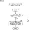
- the communication-during-discharge control unit causes the wireless communication unit to send, wirelessly, at least part of the use environment information acquired by the use environment information acquisition unit to an external communication device which is more distant from the wireless communication unit than the external power consuming device attached to the detachable casing, while the power storage device main body is discharging to the external power consuming device attached to the detachable casing and the monitoring unit indicates that the power storage device main body is discharging.
- the monitoring unit indicates that the power storage device main body outputs electric power to the external power consuming device attached to the detachable casing
- the power storage device main body is used by the external power consuming device attached to the detachable casing.
- the communication-during-discharge control unit acquires outside information transmitted from the external communication device and received by the wireless communication unit wirelessly, while the power storage device main body is discharging to the external power consuming device attached to the detachable casing and the monitoring unit indicates that the power storage device main body is discharging.
- the outside information may include information generated based on use environment information received by the external communication device.
- the outside information may include information for managing the power storage device main body.
- the communication-during-discharge type portable multi-use power storage device is able to acquire, from the external communication device, information for managing the power storage device main body in accordance with the use environment information of the power storage device main body corresponding to the external communication device.
- the versatility regarding the management of the power storage device main body can be improved.
- the applications of the communication-during-discharge type portable multi-use power storage device can therefore be extended as compared to known portable power storage devices.
- the external communication device and the communication-during-discharge type portable multi-use power storage device communicate with each other, communications between the external power consuming device and the communication-during-discharge type portable multi-use power storage device are unnecessary.
- the external power consuming device may not include communication means, for this reason.
- the applications of the communication-during-discharge type portable multi-use power storage device can therefore be further extended.
- the communication-during-discharge type portable multi-use power storage device sends information of use environment of the power storage device main body to the external communication device wirelessly, the external communication device is able to acquire the use environment from each communication-during-discharge type portable multi-use power storage device. It is therefore possible to grasp the state and tendency of each of the communication-during-discharge type portable multi-use power storage devices. By utilizing the grasped information, for example, the utilization efficiency of the power storage device main body can be improved. As a result, the applications of the communication-during-discharge type portable multi-use power storage device can be further extended.
- the power management unit manages the power storage device main body based on a monitoring result of the charge of the power storage device main body.
- the versatility regarding the management of the power storage device main body is therefore improved.
- the applications of the communication-during-discharge type portable multi-use power storage device can be further extended.
- electric power indicates electric energy unless otherwise specified, and is not electric energy per unit time.
- the power storage device main body and the management device when the detachable casing houses the power storage device main body and the management device, the power storage device main body and the management device may not be exposed to the outside at all, or part of at least one of the power storage device main body or the management device may be exposed to the outside.
- a handle which allows the detachable casing to be hand-carried may be a grip gripped by a hand, a concave into which a finger is inserted, or another type.
- the term "portable" in the communication-during-discharge type portable multi-use power storage device of the present teaching indicates that the detachable casing (power storage device) can be carried by a hand by using the handle of the detachable casing.
- the detachable casing may be carried by a hand in such a way that, for example, the power storage device is suspended, is pushed, or pulled.
- the power storage device may be detached from the floor or ground, or may be at least partially in contact with the floor or ground.
- multi-use in the communication-during-discharge type portable multi-use power storage device of the present teaching indicates that the power storage device is attachable and detachable to and from plural types of external power consuming devices, and the power storage device is usable for plural types of external power consuming devices.
- the plural types of the external power consuming devices may be plural types of external power consuming devices which are manufactured by the same manufacturer, have the same functions, and are different models (with different product numbers). Having the same functions indicate having the same major functions, and do not indicate that the external power consuming devices have completely identical functions.
- the plural types of the external power consuming devices may be plural types of external power consuming devices which are manufactured by the same manufacturer and have the same functions.
- the plural types of the external power consuming devices may be plural types of external power consuming devices which have different functions.
- a state in which a terminal portion is accessible from the outside indicates a state in which the terminal portion is electrically connectable to the external power consuming device when the detachable casing is attached to the external power consuming device.
- a state in which a terminal portion is accessible from the outside indicates a state in which the terminal portion is electrically connectable to a power supply device when the detachable casing is attached to the power supply device which is configured to supply electric power to the power storage device main body.
- the terminal portion when the terminal portion is electrically connected to the power storage device main body, the terminal portion may be directly connected to the power storage device main body, or the terminal portion may be connected to the power storage device main body via a conductive member such as a bus bar.
- the sentence that the wireless communication unit is able to send and receive information wirelessly while the power storage device main body is discharging to the external power consuming device does not indicate that the wireless communication unit is able to send and receive information wirelessly only while the power storage device main body is discharging to the external power consuming device.
- the wireless communication unit may be able to send and receive information wirelessly while the power storage device main body is not discharging to the external power consuming device.
- the use environment of the power storage device indicates the environment in which the power storage device main body is used for the external power consuming device.
- the state in which the power storage device main body is used for the external power consuming device encompasses a state in which the detachable casing is attached to the external power consuming device.
- the state in which the power storage device main body is used for the external power consuming device disregards whether the power storage device main body is discharging to the external power consuming device.
- the state in which the power storage device main body is used for the external power consuming device may encompass a state in which the detachable casing is attached to the power supply device.
- the use environment information related to the use environment of the power storage device main body may include information of the environment around the power storage device main body, may include information of the power storage device main body related to the use environment of the power storage device main body, or may include both of these sets of information.
- the information of the environment around the power storage device main body is, for example, the temperature, moisture, etc. around the power storage device main body.
- the information of the power storage device main body related to the use environment is, for example, the location of the power storage device main body, the posture (e.g., inclination) of the power storage device main body, the acceleration of the movement of the power storage device main body, the pressure on the power storage device main body, etc.
- the use environment information related to the use environment of the power storage device main body may be identification information which is set in advance for each external power consuming device.
- the use environment information does not include information directly related to discharge and charge of the power storage device main body.
- the use environment information of the power storage device main body which is discharges to the external power consuming device does not include information directly related to the discharge of the power storage device main body.
- Examples of the information directly related to the discharge and charge of the power storage device main body includes a current, a voltage, an amount of electric power stored in the power storage device main body, the state of charge (SOC) of the power storage device main body, the internal resistance of the power storage device main body, etc.
- the information directly related to the discharge and charge of the power storage device main body includes a current, a voltage, and at least one of a current or a voltage.
- the sentence that the use environment information acquisition unit acquires use environment information may indicate that use environment information sent from a sensor, a processor, etc. of the communication-during-discharge type portable multi-use power storage device is acquired (received) by the use environment information acquisition unit.
- the sentence that the use environment information acquisition unit acquires use environment information may indicate that use environment information sent from a sensor, a processor, etc. of the external power consuming device is acquired (received) by the use environment information acquisition unit.
- the sentence that the use environment information acquisition unit acquires use environment information does not indicate that the use environment information acquisition unit detects or generates use environment information.
- the sentence that the use environment information related to the use environment of the power storage device main body which is discharging to the external power consuming device is acquired does not always indicate that the acquisition is carried out while the power storage device main body is discharging to the external power consuming device.
- the use environment information may be information related to the use environment of the power storage device main body which is discharging to the external power consuming device.
- the distance between the external communication device and the wireless communication unit is longer than the distance between the external power consuming device and the wireless communication unit. If the external communication device is more distant from the communication-during-discharge type portable multi-use power storage device than the external power consuming device, the distance between the external communication device and the communication-during-discharge type portable multi-use power storage device is longer than the distance between the external power consuming device and the communication-during-discharge type portable multi-use power storage device.
- the external communication device may be closer to the communication-during-discharge type portable multi-use power storage device than the external power consuming device.
- At least one of plural options encompasses all conceivable combinations of the options. At least one of plural options may be one of the options, or all of the options. In the present teaching, at least part of a constituent feature may be part of the constituent feature or the entirety of the constituent feature.
- the number of the constituent features when the number of constituent features is not clearly specified and the constituent feature is expressed in a singular form in English, the number of the constituent features may be more than one in the present teaching. In the present teaching, the number of the constituent features may be only one.
- the term “preferable” is non-exclusive.
- the term “preferable” means “preferable but not limited to”.
- an arrangement which is “preferable” exerts at least the above-described effects of the arrangement (1) above.
- the term “may” is non-exclusive.
- the term “may” indicate “may but not must”.
- an arrangement which is explained by using the term “may” exerts at least the above-described effects of the arrangement (1) above.
- the present teaching is not limited to the configurations and layout of elements described below and/or shown in drawings.
- the present teaching may be implemented as an embodiment other than the below-described embodiment.
- the present teaching may be implemented as an embodiment other than the below-described embodiment.
- the present teaching may be implemented by suitably combining below-described modifications.
- a portable power storage device attachable and detachable to and from an external power consuming device consuming electric power can be used for various types of external power consuming devices.
- a communication-during-discharge type portable multi-use power storage device 1 of the present embodiment includes a power storage device main body 2, a management device 3, a detachable casing 4, and a terminal portion 5.
- the power storage device main body 2 is arranged to be able to store electric power.
- the detachable casing 4 houses the power storage device main body 2 and the management device 3.
- the detachable casing 4 is attachable and detachable to and from plural types of external power consuming devices 100A, 100B, 100C, and 100D.
- the external power consuming devices 100A, 100B, 100C, and 100D will be collectively termed external power consuming devices 100.
- FIG. 1 schematically shows the internal structure of the communication-during-discharge type portable multi-use power storage device 1.
- the ratio in size of the power storage device main body 2 to the management device 3 shown in FIG. 1 is different from the actual ratio.
- the power storage device main body 2 is larger in size than the management device 3.
- the detachable casing 4 causes the power storage device main body 2 and the management device 3 to be integrally attachable and detachable to and from the external power consuming device 100.
- the detachable casing 4 has a handle 4a by which the detachable casing 4 is carried by a hand H. It is therefore possible to carry the power storage device main body 2 and the management device 3 together by using the handle 4a. Furthermore, it is possible to attach the power storage device main body 2 and the management device 3 together to each of the external power consuming device 100 by using the handle 4a. Furthermore, it is possible to detach the power storage device main body 2 and the management device 3 together from each of the external power consuming device 100 by using the handle 4a.
- the terminal portion 5 is provided on the detachable casing 4 to be accessible from the outside of the detachable casing 4.
- the terminal portion 5 is electrically connected to the power storage device main body 2.
- the terminal portion 5 is arranged to be able to transmit electric power between the outside of the detachable casing 4 and the power storage device main body 2.
- the terminal portion 5 is able to supply electric power stored in the power storage device main body 2 to the external power consuming device 100 attached to the detachable casing 4, irrespective of the type of the external power consuming device 100 attached to the detachable casing 4.
- the management device 3 includes a power management unit 10, a monitoring unit 11, a wireless communication unit 12, a use environment information acquisition unit 13, and a communication-during-discharge control unit 14.
- the power management unit 10 is configured to manage the power storage device main body 2.
- the monitoring unit 11 monitors discharge from the power storage device main body 2 to the external power consuming device 100 attached to the detachable casing 4 no matter to which one of the external power consuming devices 100 of plural types the detachable casing 4 is attached.
- the wireless communication unit 12 is able to send and receive information wirelessly while the power storage device main body 2 is discharging to the external power consuming device 100 attached to the detachable casing 4, no matter to which one of the external power consuming devices 100 of plural types the detachable casing 4 is attached.
- the use environment information acquisition unit 13 acquires use environment information which is related to the use environment of the power storage device main body 2 discharging to the external power consuming device 100 attached to the detachable casing 4 and corresponds to the external power consuming device 100 attached to the detachable casing 4, no matter to which one of the external power consuming devices 100 of plural types the detachable casing 4 is attached.
- the communication-during-discharge control unit 14 causes the wireless communication unit 12 to send, wirelessly, at least part of the use environment information acquired by the use environment information acquisition unit 13 to an external communication device 200 which is more distant from the wireless communication unit 12 than the external power consuming device 100 attached to the detachable casing 4, while the power storage device main body 2 is discharging to the external power consuming device 100 attached to the detachable casing 4 and the monitoring unit 11 indicates that the power storage device main body 2 is discharging.
- the monitoring unit 11 When the monitoring unit 11 indicates that the power storage device main body 2 outputs electric power to the external power consuming device 100 attached to the detachable casing 4, the power storage device main body 2 is used by the external power consuming device 100.
- the communication-during-discharge control unit 14 acquires outside information transmitted from the external communication device 200 and received by the wireless communication unit 12 wirelessly, while the power storage device main body 2 is discharging to the external power consuming device 100 attached to the detachable casing 4 and the monitoring unit 11 indicates that the power storage device main body 2 is discharging.
- the outside information may include information generated based on use environment information received by the external communication device 200.
- the outside information may include information for managing the power storage device main body 2.
- the communication-during-discharge type portable multi-use power storage device 1 is able to acquire, from the external communication device 200, information for managing the power storage device main body 2 in accordance with the use environment information of the power storage device main body 2 corresponding to the external communication device 200.
- the versatility regarding the management of the power storage device main body 2 can be improved.
- the applications of the communication-during-discharge type portable multi-use power storage device 1 can therefore be extended as compared to known portable power storage devices.
- the external communication device 200 and the communication-during-discharge type portable multi-use power storage device 1 communicate with each other, communications between the external power consuming device 100 and the communication-during-discharge type portable multi-use power storage device 1 are unnecessary.
- the external power consuming device 100 may not include communication means, for this reason.
- the applications of the communication-during-discharge type portable multi-use power storage device 1 can therefore be further extended.
- the communication-during-discharge type portable multi-use power storage device 1 sends information of use environment of the power storage device main body 2 to the external communication device 200 wirelessly, the external communication device 200 is able to acquire the use environment from each communication-during-discharge type portable multi-use power storage device 1. It is therefore possible to grasp the state and tendency of each of the communication-during-discharge type portable multi-use power storage devices 1. By utilizing the grasped information, for example, the utilization efficiency of the power storage device main body 2 can be improved. As a result, the applications of the communication-during-discharge type portable multi-use power storage device 1 can be further extended.
- Specific Example 1 of the embodiment of the present teaching will be described with reference to FIG. 1 to FIG. 7 .
- Specific Example 1 of the embodiment of the present teaching encompasses all features of the embodiment of the present teaching described above. Members identical with those in the above-described embodiment of the present teaching are not explained again. The following will describe arrangements which are different from those of the above-described embodiments of the present teaching.
- FIG. 1 shows an example in which the communication-during-discharge type portable multi-use power storage device 1 is used for four external power consuming devices 100A, 100B, 100C, and 100D.
- the communication-during-discharge type portable multi-use power storage device 1 is arranged to be attachable and detachable to and from plural types of external power consuming devices 100 (see FIG. 2 ).
- the external power consuming devices 100 are any types of devices as long as they consume electric power.
- the external power consuming devices 100 are devices which are driven by supplied electric power.
- the communication-during-discharge type portable multi-use power storage device 1 discharges to (supplies electric power to) the external power consuming device 100 no matter to which one of the external power consuming devices 100 of plural types the apparatus 1 is attached,
- the external power consuming devices 100 may be consumer apparatuses or industrial apparatuses.
- the consumer apparatuses are used by general consumers or used in home, whereas the industrial apparatuses are used in industrial fields.
- a consumer apparatus is, for example, a home electric appliance. Examples of the home electric appliance include an air conditioner, a refrigerator, a washing machine, a dryer, a television, and a gaming machine, etc.
- Examples of the industrial apparatus include a construction machine, a civil engineering machine, an electric tool (e.g., a welding device), a transporting machine (e.g., carriage) used in a warehouse or a factory, a portable air conditioner (e.g., a spot cooler or a spot heater), an inboard machine (e.g., a fish finder and a wireless communications apparatus), a broadcasting device (e.g., a data storage, a broadcasting device used for relay broadcasting, or emergency broadcasting equipment), an audio device (e.g., a power amplifier), an emergency device (e.g., a cooking device or a water purifier), an amusement device for an amusement facility, etc.
- a construction machine e.g., a civil engineering machine, an electric tool (e.g., a welding device), a transporting machine (e.g., carriage) used in a warehouse or a factory, a portable air conditioner (e.g., a spot cooler or a spot heater), an in
- the external power consuming device 100A shown in FIG. 1 is an example of a spot cooler.
- the spot cooler is provided in a factory, etc.
- the spot cooler 100A includes a blowing pipe 110 through which cool air (cool wind) is blown out.
- the spot cooler 100A has wheels to facilitate a user to manually move the spot cooler 100A.
- the external power consuming device 100B shown in FIG. 1 is an example of a rack transporter used in a warehouse or a factory.
- the rack transporter 100B is a device for transporting a rack S (indicated by two-dot chain lines in FIG. 2 ) on which an object is placed.
- the rack transporter 100B is configured to be able to run on the floor.
- the rack transporter 100B is configured to be able to automatically run based on information received wirelessly.
- the rack transporter 100B includes a rack supporter 120 which is movable in the up-down direction. With the lowered rack supporter 120, the rack transporter 100B runs to a space under the lowest shelf of the rack S (indicated by two-dot chain lines in FIG. 2 ). As the rack supporter 120 moves up in this state, the rack S is moved up. As the rack transporter 100B runs in this state, the rack S is transported.
- the external power consuming device 100 may be an electric vehicle (electric mobile body).
- the electric vehicle may be a consumer apparatus or an industrial apparatus.
- the electric vehicle may have a motor as the only power source, or may have a motor and an internal combustion engine as power sources.
- the electric vehicle may be manned or unmanned.
- a manned electric vehicle may be driven by a driver or may be automatically driven.
- the electric vehicle may be able to run on any route or may be able to run only on a predetermined route.
- the electric vehicle may run on the land, on the water, in the water, or in the air.
- the electric vehicle running on the land is, for example, a four-wheeled vehicle, a bicycle, a tricycle, or a snowmobile, etc.
- the electric vehicle running on the land may be a vehicle having more than four wheels.
- the four-wheeled vehicle is, for example, a passenger vehicle, an ATV (All Terrain Vehicle), an ROV (Recreational Off-highway Vehicle), a golf cart, or a forklift, etc.
- the electric vehicle running on the water is, for example, a ship or a personal water craft, etc.
- the electric vehicle running in the water is, for example, a submarine, etc.
- the electric vehicle running in the air is, for example, an airplane, a helicopter, or a drone, etc.
- the external power consuming device 100C shown in FIG. 1 is an example of a motorcycle (to be more specific, a scooter).
- the detachable casing 4 is entirely covered with a vehicle body cover or a seat of the motorcycle 100C.
- the motorcycle 100C may be arranged so that the detachable casing 4 is partially exposed to the outside.
- the external power consuming device 100 may be a typical external power consuming device which receives electric power from an engine generator.
- a known engine generator has various output voltages and generation capacities, but its operation voltage or generation capacity is relatively high or large.
- the external power consuming device 100 may be a distribution device.
- the external power consuming device 100D shown in FIG. 1 is an example of the distribution device.
- the distribution device includes a power output unit to which at least one plug is insertable. In the case of the distribution device 100D shown in FIG. 1 , the reference symbol 140 indicates the power output unit.
- Each of the at least one plug may be an electric plug.
- Each of the at least one plug may be an USB plug.
- the at least one plug may include both an electric plug and an USB plug.
- the at least one plug may include a plug which is different from these two types of the plugs.
- the distribution device may include an AC/DC converter configured to convert DC to AC.
- the distribution device may include an electrical transformer configured to change the voltage.
- the distribution device is used in order to supply electric power of the communication-during-discharge type portable multi-use power storage device 1 to an electric apparatus which is not attachable and detachable to and from the communication-during-discharge type portable multi-use power storage device 1.
- the distribution device it is possible to supply electric power of the communication-during-discharge type portable multi-use power storage device 1 to electric apparatus whose operating voltage is lower than the output voltage of the communication-during-discharge type portable multi-use power storage device 1.
- the distribution device 100D shown in FIG. 1 has two handles 141 which can be gripped by hands.
- the distribution device 100D is therefore easily carried in a state that the communication-during-discharge type portable multi-use power storage device 1 is attached to the distribution device 100D.
- the distribution device may not have such handles. Because the distribution device alone is relatively light in weight, the distribution device alone is easily carried.
- the distribution device 100D shown in FIG. 1 has wheels to facilitate a user to manually move the distribution device 100D easily. The distribution device may not have such wheels.
- External power consuming devices 100 of plural types for which one communication-during-discharge type portable multi-use power storage device 1 can be used, may have different functions.
- the external power consuming devices 100 of plural types may include both an industrial apparatus and a consumer apparatus.
- External power consuming devices 100 of plural types, for which one communication-during-discharge type portable multi-use power storage device 1 can be used may be manufactured by different manufacturers but have the same function.
- External power consuming devices 100 of plural types, for which one communication-during-discharge type portable multi-use power storage device 1 can be used may be manufactured by the same manufacturer, have the same function, and be different models (with different product numbers).
- the communication-during-discharge type portable multi-use power storage device 1 When not attached to the external power consuming device 100, the communication-during-discharge type portable multi-use power storage device 1 is attachable to a power supply device (not illustrated).
- the detachable casing 4 is attachable and detachable to and from the power supply device (charging device).
- the power supply device is configured to supply electric power to the communication-during-discharge type portable multi-use power storage device 1.
- Charge of the communication-during-discharge type portable multi-use power storage device 1 may start when the communication-during-discharge type portable multi-use power storage device 1 is attached to the power supply device.
- the communication-during-discharge type portable multi-use power storage device 1 may be able to receive electric power supplied from a power source (not illustrated) via the external power consuming device 100 while being attached to the external power consuming device 100.
- Charge of the communication-during-discharge type portable multi-use power storage device 1 may start when the power source is connected to the external power consuming device 100 or the external power consuming device 100 is operated to start charging.
- whether charge of the communication-during-discharge type portable multi-use power storage device 1 while being attached to the external power consuming device 100 is possible depends on the structure of the external power consuming device 100.
- All of the external power consuming devices 100 of plural types, for which one communication-during-discharge type portable multi-use power storage device 1 can be used, may allow such charging.
- charge of the communication-during-discharge type portable multi-use power storage device 1 by the power source may be possible no matter to which one of the external power consuming devices 100 of plural types the detachable casing 4 is attached.
- only one or more of the external power consuming devices 100 may allow such charging.
- charge of the communication-during-discharge type portable multi-use power storage device 1 by the power source may be possible when the detachable casing 4 is attached to an external power consuming device 100 which is the one or more of the external power consuming devices 100.
- the communication-during-discharge type portable multi-use power storage device 1 may be chargeable by the power source while being attached to each of the external power consuming devices 100A, 100B, 100C, and 100D shown in FIG. 1 .
- the rack transporter 100B may automatically run to the power source when the charge is required.
- a power input unit 130 of the motorcycle 100C may be connected to a plug of the power source in order for the power storage device main body 2 to be charged.
- the communication-during-discharge type portable multi-use power storage device 1 includes the power storage device main body 2, the management device 3, the detachable casing 4, and the terminal portion 5.
- the power storage device main body 2 is configured to be able to store electric power.
- the power storage device main body 2 is configured to be able to output stored electric power.
- the power storage device main body 2 is configured to be rechargeable.
- the power storage device main body 2 is, for example, a secondary battery, a super capacitor, or an ultracapacitor.
- the power storage device main body 2 may be a battery pack having plural cells.
- the power storage device main body 2 may include plural super capacitors or plural ultracapacitors.
- the power storage device main body 2 is not limited to these arrangements.
- the detachable casing 4 houses the power storage device main body 2 and the management device 3.
- the detachable casing 4 has the handle 4a.
- the handle 4a is a grip which can be gripped by a hand H (see FIG. 1 ).
- the detachable casing 4 is attachable and detachable to and from the external power consuming device 100.
- the detachable casing 4 therefore causes the power storage device main body 2 and the management device 3 to be integrally attachable and detachable to and from the external power consuming device 100.
- a user can carry the communication-during-discharge type portable multi-use power storage device 1 in a suspended state, by gripping the handle 4a by a hand.
- the handle 4a may not be shaped as a grip.
- the handle 4a may have any shape as long as the communication-during-discharge type portable multi-use power storage device 1 can be carried by a hand.
- the way of arranging the detachable casing 4 to be attachable and detachable to and from the external power consuming device 100 is not limited.
- the way of arranging the detachable casing 4 to be attachable and detachable to and from the external power consuming device 100 may utilize magnetic force, a thread locking mechanism, or a fitting structure with a protrusion and a concave.
- the way of arranging the detachable casing 4 to be attachable and detachable to and from the power supply device (not illustrated) is not limited.
- the terminal portion 5 is provided on the detachable casing 4.
- the terminal portion 5 is electrically connected to the power storage device main body 2.
- the terminal portion 5 is connected to an electrode terminal of the power storage device main body 2 via the management device 3.
- the terminal portion 5 is formed of a pair of electrode terminals 5a and 5b.
- the pair of electrode terminals 5a and 5b is formed of a cathode terminal (positive terminal) 5a and an anode terminal (negative terminal) 5b.
- the terminal portion 5 is provided on the detachable casing 4 to be accessible from the outside. The way of arranging the terminal portion 5 to be accessible from the outside is not limited.
- terminal portion 5 is exposed to the outside through an opening formed through the detachable casing 4, the terminal portion 5 is accessible from the outside.
- the terminal portion 5 transmits electric power between the outside of the detachable casing 4 and the power storage device main body 2.
- the terminal portion 5 supplies electric power stored in the power storage device main body 2 to the external power consuming device 100 no matter to which one of the external power consuming devices 100 of plural types the detachable casing 4 is attached. Electric power is supplied to the terminal portion 5 from the power supply device or the power source.
- the power storage device main body 2 is configured to store the electric power supplied to the terminal portion 5.
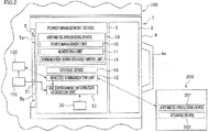
- FIG. 1 and FIG. 2 show functional block diagrams of the communication-during-discharge type portable multi-use power storage device 1.
- the management device 3 includes an arithmetic processing device (processor) 15 and a storage device 16.
- the arithmetic processing device 15 is, for example, a CPU (Central Processing Unit), a GPU (Graphics Processing Unit), a microcontroller, a micro processing unit, an application specific integrated circuit (ASIC), a programmable logic circuit (PLC), or a field programmable gate array (FPGA), etc.
- the storage device 16 stores data.
- the storage device 16 stores information necessary for processes executed by the arithmetic processing device 15,
- the storage device 16 includes, for example, a ROM (Read Only Memory), or a RAM (Random Access Memory).
- the RAM temporarily stores data when the arithmetic processing device 15 executes a program.
- the ROM stores a program executed by the arithmetic processing device 15. As a program stored in the storage device 16 is executed by the arithmetic processing device 15, functional units are embodied.
- the management device 3 includes the power management unit 10, the monitoring unit 11, and the communication-during-discharge control unit 14 which are functional units.
- the power management unit 10 is a functional unit which is embodied as a power management program stored in the storage device 16 is executed by the arithmetic processing device 15.
- the monitoring unit 11 is a functional unit which is embodied as a monitoring program stored in the storage device 16 is executed by the arithmetic processing device 15.
- the communication-during-discharge control unit 14 is a functional unit which is embodied as a communication control program stored in the storage device 16 is executed by the arithmetic processing device 15.
- the management device 3 includes the use environment information acquisition unit 13.
- the use environment information acquisition unit 13 is formed of hardware.
- the use environment information acquisition unit 13 may be part of the arithmetic processing device 15.
- the power management unit 10 is configured to manage the power storage device main body 2.
- the power management unit 10 is constituted by a so-called BMS (Battery Management System).
- the power management unit 10 is configured to manage the charge and discharge of the power storage device main body 2.
- the power management unit 10 manages, for example, an amount of electric power stored in the power storage device main body 2.
- the power management unit 10 may manage the power storage device main body 2 based on information directly acquired from the monitoring unit 11. As detailed later, the monitoring unit 11 is configured to monitor the state of the power storage device main body 2. In other words, the power management unit 10 may manage the power storage device main body 2 based on a result of monitoring of the power storage device main body 2 by the monitoring unit 11. The power management unit 10 may manage the power storage device main body 2 based on information sent from the external communication device 200. In the specific example of the present embodiment, the external communication device 200 is a server. The external communication device 200 may not be a server. The power management unit 10 may manage the power storage device main body 2 based on information directly acquired from the use environment information acquisition unit 13.
- the use environment information acquisition unit 13 acquires information related to the use environment of the power storage device main body 2.
- the power management unit 10 may use the above-described information for managing the power storage device main body 2 alone or may generate new information by combining the above-described information with another set of information.
- the management device 3 includes the wireless communication unit 12.
- the wireless communication unit 12 is a device for wireless communications.
- the wireless communication unit 12 is able to send and receive information wirelessly.
- the wireless communication unit 12 is able to send and receive information wirelessly while the power storage device main body 2 is discharging to the external power consuming device 100.
- the wireless communication unit 12 may be able to at least send or receive information wirelessly in one of the following four cases.
- the wireless communication unit 12 may be able to send and receive information wirelessly in all of the following four cases.
- the first case is a case where a power storage device 1 is attached to the external power consuming device 100 and the power storage device main body 2 is performing neither discharging nor charging.
- the second case is a case where the power storage device main body 2 is being charged by a power supplier or a power source.
- the third case is a case where the power storage device 1 is attached to the power supply device and the power storage device main body 2 is not being charged.
- the fourth case is a case where the power storage device 1 is attached to none of the external power consuming device 100 and the power supply device.
- the wireless communication unit 12 is able to mutually communicate with the external communication device 200.
- the wireless communication unit 12 is able to mutually communicate with the external communication device 200 while the power storage device main body 2 is outputting electric power to the external power consuming device 100.
- the wireless communication unit 12 may be able to mutually or one-way communicate with the external communication device 200 while the power storage device main body 2 does not output electric power to the external power consuming device 100.
- the external communication device 200 is physically distant from the communication-during-discharge type portable multi-use power storage device 1.
- the distance between the external communication device 200 and the communication-during-discharge type portable multi-use power storage device 1 is almost always longer than the distance between the external power consuming device 100 and the communication-during-discharge type portable multi-use power storage device 1.
- the external communication device 200 is more distant from the communication-during-discharge type portable multi-use power storage device 1 than the external power consuming device 100.
- the wireless communication unit 12 may be able to mutually or one-way communicate with an apparatus which is different from the external communication device 200.
- the wireless communication unit 12 may be able to mutually communicate with the power supply device.
- the wireless communication unit 12 may be able to mutually communicate with an external power consuming device 100.
- the wireless communication unit 12 may be able to mutually communicate with a mobile communication device such as a smartphone.
- the communication system of the wireless communication unit 12 is not limited.
- the wireless communication unit 12 may be able to use plural communication systems. Communications between the wireless communication unit 12 and the external communication device 200 may be performed by a combination of plural communication systems. Communications between the wireless communication unit 12 and the external communication device 200 may be performed solely wirelessly communication, or by wired communication in addition to wireless communication. Communications between the wireless communication unit 12 and the external communication device 200 may or may not use the Internet. Communications between the wireless communication unit 12 and the external communication device 200 may be done by using a mobile phone communication system. The wireless communication unit 12 may send and receive information by using a mobile phone communication system.
- Examples of the mobile phone communication system used by the wireless communication unit 12 include Cellular networks such as 3G (3rd Generation), 4G (4th Generation), LTE (Long Term Evolution).
- the mobile phone communication system used by the wireless communication unit 12 may be a communication system established after the application date of the subject application. Communications between the wireless communication unit 12 and the external communication device 200 may be done by using a wireless LAN such as Wi-Fi.
- the wireless communication unit 12 may send and receive information by using a wireless LAN. Communications between the wireless communication unit 12 and the external communication device 200 may be done by using satellite communication.
- the wireless communication unit 12 may have a short-range communication function which is not used for communicating with the external communication device 200. Examples of the short-range communication function which is not used for communicating with the external communication device 200 include Bluetooth (registered trademark), NFC (Near Field Communication), etc.
- the external communication device 200 is configured to acquire information sent from the management device 3.
- the external communication device 200 is configured to acquire information sent from plural communication-during-discharge type portable multi-use power storage devices 1.
- the external communication device 200 executes a suitable process to the acquired information. With this, the external communication device 200 generates information to be sent to the management device 3, and sends the information to the management device 3. In other words, based on information sent from one communication-during-discharge type portable multi-use power storage device 1, the external communication device 200 generates information to be sent to the management device 3 of the one communication-during-discharge type portable multi-use power storage device 1.
- the external communication device 200 may generate information to be sent to the management device 3 of another communication-during-discharge type portable multi-use power storage device 1.
- Information to be sent to the management device 3 may include an instruction for managing the power storage device main body 2.
- the external communication device 200 manages the communication-during-discharge type portable multi-use power storage device 1.
- the external communication device 200 manages plural communication-during-discharge type portable multi-use power storage devices 1.
- the external communication device 200 may send, to the management device 3, information other than the instruction for managing the power storage device main body 2.
- the external communication device 200 includes an arithmetic processing device 201 and a storage device 202.
- a specific example of the arithmetic processing device 201 is identical to the specific example of the arithmetic processing device 15.
- a specific example of the storage device 202 is identical to the specific example of the storage device 16.
- the storage device 202 stores information necessary for processes executed by the arithmetic processing device 201.
- the monitoring unit 11 is configured to monitor the state of the power storage device main body 2.
- the monitoring unit 11 monitors input and output of a current to and from the power storage device main body 2 and an amount of electric power stored in the power storage device main body 2.
- the monitoring unit 11 performs the monitoring based on signals from an unillustrated sensor (e.g., a current sensor) of the communication-during-discharge type portable multi-use power storage device 1.
- the unillustrated sensor is provided at a circuit which connects the terminal portion 5 with the power storage device main body 2.
- the monitoring unit 11 may monitor the voltage of the power storage device main body 2. This monitoring is performed based on signals from an unillustrated sensor (e.g., a voltage sensor) of the communication-during-discharge type portable multi-use power storage device 1, too.
- the monitoring unit 11 is configured to monitor the discharge of the power storage device main body 2. In other words, the monitoring unit 11 monitors the discharge from the power storage device main body 2 to the external power consuming device 100. The monitoring unit 11 monitors the discharge of the power storage device main body 2 based on at least one of the output of a current from the power storage device main body 2 or an amount of electric power stored in the power storage device main body 2. The monitoring of the discharge of the power storage device main body 2 may indicate the monitoring of only whether the power storage device main body 2 discharges or not. To be more specific, for example, the monitoring unit 11 monitors whether the power storage device main body 2 outputs a current. The monitoring of the discharge of the power storage device main body 2 may indicate monitoring of a change of electric power output from the power storage device main body 2.
- the monitoring unit 11 may monitor a change of the electric power output from the power storage device main body 2 by continuously or intermittently monitoring an amount of electric power stored in the power storage device main body 2.
- the monitoring unit 11 may monitor a change of electric power output from the power storage device main body 2 based on a result of measurement of time during which a current is output from the power storage device main body 2.
- the monitoring unit 11 is configured to monitor the charge of the power storage device main body 2. In other words, the monitoring unit 11 monitors the supply of electric power to the power storage device main body 2 from the power supply device or the power source. The monitoring unit 11 monitors the charge of the power storage device main body 2 based on at least one of the input of a current to the power storage device main body 2 or an amount of electric power stored in the power storage device main body 2. The monitoring of the charge of the power storage device main body 2 may indicate monitoring of only whether the power storage device main body 2 is charged or not. To be more specific, for example, the monitoring unit 11 may monitor whether or not a current is input to the power storage device main body 2.
- the monitoring unit 11 may monitor whether the power storage device main body 2 is electrically connected to the power supply device.
- the monitoring of the charge of the power storage device main body 2 may indicate monitoring of a change of electric power supplied to the power storage device main body 2.
- a change of the electric power supplied to the power storage device main body 2 may be monitored by continuously or intermittently monitoring an amount of electric power stored in the power storage device main body 2.
- the monitoring unit 11 may monitor a change of electric power supplied to the power storage device main body 2 based on a result of measurement of time during which a current is input to the power storage device main body 2.
- the monitoring unit 11 is configured to monitor whether a current input to or output from the power storage device main body 2 is an overcurrent.
- the overcurrent indicates a current which exceeds a predetermined value (acceptable value) which is set in advance in the power storage device main body 2.
- the power management unit 10 manages a current input to or output from the power storage device main body 2 not to become an overcurrent based on a monitoring result of the power storage device main body 2 by the monitoring unit 11.
- the monitoring unit 11 detects that a current input to the power storage device main body 2 is an overcurrent
- the power management unit 10 stops the charge of the power storage device main body 2.
- the power management unit 10 stops the discharge of the power storage device main body 2.
- the monitoring unit 11 is configured to monitor whether the power storage device main body 2 is in an overcharged state.
- the overcharged state is a state in which the power storage device main body 2 in a fully charged state is storing more electric charges.
- the fully charged state is a state in which the charged amount is identical with the electrical capacity of the power storage device main body 2.
- the monitoring unit 11 is able to monitor whether the power storage device main body 2 is in the overcharged state by monitoring whether the voltage of the power storage device main body 2 exceeds a predetermined value.
- the power management unit 10 manages the power storage device main body 2 not to be in the overcharged state based on a monitoring result of the power storage device main body 2 by the monitoring unit 11.
- the monitoring unit 11 is configured to monitor whether the power storage device main body 2 is in an over-discharged state.
- the over-discharged state is a state in which electric charges are excessively discharged from the power storage device main body 2 and hence the voltage of the power storage device main body 2 is lower than the discharge cut off voltage.
- the monitoring unit 11 is able to monitor whether the power storage device main body 2 is in the over-discharged state by monitoring the voltage of the power storage device main body 2.
- the power management unit 10 manages the power storage device main body 2 not to be in the over-discharged state based on a monitoring result of the power storage device main body 2 by the monitoring unit 11.
- the monitoring unit 11 may monitor the cumulative time of the discharge of the power storage device main body 2.
- the monitoring unit 11 may monitor the discharge of the power storage device main body 2 based on this monitoring result.
- the monitoring unit 11 may monitor the cumulative time of the charge of the power storage device main body 2.
- the monitoring unit 11 may monitor the charge of the power storage device main body 2 based on this monitoring result.
- the arithmetic processing device 15 of the management device 3 may estimate the degree of deterioration of the power storage device main body 2 based on a monitoring result by the monitoring unit 11.
- the monitoring unit 11 may monitor whether the power storage device 1 is attached to the external power consuming device 100. Based on a combination of this monitoring result and a monitoring result of the discharge of the power storage device main body 2, it is possible to grasp that the external power consuming device 100 to which the power storage device 1 is attached is in a state of not consuming electric power (e.g., a standby state such as a power save mode). This monitoring may be performed as below, for example.
- a sensor is provided in the communication-during-discharge type portable multi-use power storage device 1 or the external power consuming device 100 to detect whether the power storage device 1 is attached to the external power consuming device 100.
- the monitoring unit 11 may monitor whether the power storage device 1 is attached to the external power consuming device 100, based on a detection result of this sensor.
- the information indicating whether the power storage device 1 is attached to the external power consuming device 100 may be included in later-described use environment information. In such a case, a functional unit which determines whether the power storage device 1 is attached to the external power consuming device 100 may not be included in the monitoring unit 11.
- the monitoring unit 11 may monitor whether the power storage device 1 is attached to the power supply device. Based on a combination of this monitoring result and a monitoring result of the charge of the power storage device main body 2, it is possible to grasp that the power supply device to which the power storage device 1 is attached is in a state of not supplying electric power to the power storage device main body 2 (e.g., a state after the completion of the charge). This monitoring may be performed as below, for example.
- a sensor is provided in the communication-during-discharge type portable multi-use power storage device 1 or the power supply device to detect whether the power storage device 1 is attached to the power supply device.
- the monitoring unit 11 may monitor whether the power storage device 1 is attached to the power supply device, based on a detection result of this sensor.
- the information indicating whether the power storage device 1 is attached to the power supply device may be included in later-described use environment information.
- a functional unit which determines whether the power storage device 1 is attached to the power supply device may not be included in the monitoring unit 11.
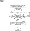
- the use environment information acquisition unit 13 acquires use environment information related to the use environment of the power storage device main body 2.
- the use environment of the power storage device main body 2 i.e., the environment in which the power storage device main body 2 is used
- the use environment of the power storage device main body 2 is the environment in which the detachable casing 4 is attached to the external power consuming device 100 or the power supply device.
- the use environment information acquisition unit 13 acquires use environment information related to the use environment of the power storage device main body 2 in the power storage device 1 attached to the external power consuming device 100.
- the use environment information acquisition unit 13 acquires use environment information related to the use environment of the power storage device main body 2 which is discharging to the external power consuming device 100.
- the use environment information acquisition unit 13 may acquire use environment information related to the use environment of the power storage device main body 2 in the power storage device 1 attached to the external power consuming device 100, the power storage device main body 2 performing neither the charge nor the discharge.
- the use environment information acquisition unit 13 may acquire use environment information related to the use environment of the power storage device main body 2 which is being charged by the power supply device or the power source.
- the use environment information acquisition unit 13 may acquire use environment information related to the use environment of the power storage device main body 2 in the power storage device 1 attached, the power storage device main body 2 not being charged.
- the use environment information acquisition unit 13 may acquire storage environment information related to storage environment of the power storage device main body 2 in the power storage device 1 attached neither to the external power consuming device 100 nor to the power supply device.
- the use environment information acquisition unit 13 may acquire use environment information sent from a sensor or an arithmetic processing device (hereinafter, these members will be referred to as a sensor, etc.) provided in the communication-during-discharge type portable multi-use power storage device 1.
- the use environment information acquisition unit 13 acquires, through a wire, use environment information (signal) sent from a sensor 20 of the communication-during-discharge type portable multi-use power storage device 1.
- the use environment information acquisition unit 13 may acquire use environment information sent from a sensor or an arithmetic processing device (hereinafter, these members will be referred to as a sensor, etc.) provided in the external power consuming device 100.
- a sensor or an arithmetic processing device hereinafter, these members will be referred to as a sensor, etc.
- the use environment information acquisition unit 13 acquires use environment information (signal) sent from a sensor 101 of the external power consuming device 100.
- the communication-during-discharge type portable multi-use power storage device 1 may include a terminal 21 by which communication with the external power consuming device 100 is performed, and the use environment information acquisition unit 13 may acquire use environment information sent from the sensor 101 via the terminal 21.
- the use environment information acquisition unit 13 may acquire use environment information sent from the sensor 101 wirelessly communication between a wireless communication device 102 of the external power consuming device 100 and the wireless communication unit 12.
- the use environment information acquisition unit 13 may acquire use environment information sent from a sensor, etc. which is provided in the power supply device.
- the use environment information acquisition unit 13 acquires storage environment information sent from a sensor, etc. (e.g., the sensor 20) provided in the communication-during-discharge type portable multi-use power storage device 1.
- the use environment information related to the use environment of the power storage device main body 2 may include information of the surrounding environment of the power storage device main body 2, or may include information of the power storage device main body 2 itself, which relates to the use environment of the power storage device main body 2.
- the use environment information may be information indicating a temporal change.
- the use environment information acquisition unit 13 may acquire information of the surrounding environment of the power storage device main body 2 from a sensor, etc. (e.g., the sensor 20) of the communication-during-discharge type portable multi-use power storage device 1, from a sensor, etc. (e.g., the sensor 101) of the external power consuming device 100, or from a sensor, etc. of the power supply device.
- the use environment information acquisition unit 13 may acquire information of the power storage device main body 2 itself related to the use environment of the power storage device main body 2 from a sensor, etc. (e.g., the sensor 20) of the communication-during-discharge type portable multi-use power storage device 1, from a sensor, etc. (e.g., the sensor 101) of the external power consuming device 100, or from a sensor, etc. of the power supply device. All sets of use environment information acquired by the use environment information acquisition unit 13 may be sent from a sensor, etc. of the communication-during-discharge type portable multi-use power storage device 1. All sets of use environment information acquired by the use environment information acquisition unit 13 may not be sent from a sensor, etc. of the communication-during-discharge type portable multi-use power storage device 1.
- the information of the surrounding environment of the power storage device main body 2 may include information related to the temperature around the power storage device main body 2.
- the information related to the temperature may be a temperature, a voltage signal from a temperature sensor, or information by which a temperature can be indirectly understood.
- the information of the surrounding environment of the power storage device main body 2 may include information related to the moisture around the power storage device main body 2.
- the information related to the moisture may be a moisture, a voltage signal from a moisture sensor, or information by which a moisture can be indirectly understood.
- the information of the surrounding environment of the power storage device main body 2 may include information related to the air pressure around the power storage device main body 2.
- the information related to the air pressure may be an air pressure, a voltage signal from an air pressure sensor, or information by which an air pressure can be indirectly understood (e.g., altitude).
- the altitude may be calculated based on the information of absolute location and map data.
- the information of the power storage device main body 2 itself related to the use environment of the power storage device main body 2 may include information related to the location of the power storage device main body 2.
- the information related to the location of the power storage device main body 2 may be information of the absolute location of the power storage device main body 2 (e.g., longitude and latitude).
- the information of the absolute location may be a GNSS signal received by a GNSS receiver.
- GNSS stands for Global Navigation Satellite System.
- the wireless communication unit 12 may function as a GNSS receiver.
- the information related to the location of the power storage device main body 2 may be information of the relative location of the power storage device main body 2.
- the reference point of the relative location is not limited.
- the information of the power storage device main body 2 itself related to the use environment of the power storage device main body 2 may include information related to the posture of the power storage device main body 2.
- the information related to the posture of the power storage device main body 2 may be information of the inclination of the power storage device main body 2.
- the information of the inclination of the power storage device main body 2 may be a rotational angle of the power storage device main body 2 relative to the reference position, the rotational angular speed of the power storage device main body 2, or the rotational angular acceleration of the power storage device main body 2.
- the information of the inclination of the power storage device main body 2 may be information related to the rotation (inclination) about three axes, or information related to the rotation (inclination) about one axis or two axes,
- the information of the inclination of the power storage device main body 2 may include, for example, a signal detected by a gyroscope (angular speed sensor) or a value calculated based on the signal.
- the information of the inclination of the power storage device main body 2 may include, for example, a signal detected by at least one angular acceleration sensor or a value calculated based on the signal.
- the information related to the posture of the power storage device main body 2 may be information of the orientation of the attached communication-during-discharge type portable multi-use power storage device 1.
- the information of the power storage device main body 2 itself related to the use environment of the power storage device main body 2 may include information related to the speed of the movement of the power storage device main body 2.
- the information related to the speed may be speed, a voltage signal from a speed sensor, or information by which speed can be indirectly understood.
- the speed of the movement of the power storage device main body 2 may be the speed of the movement of the external power consuming device 100.
- the external power consuming device 100 is a motorcycle 100C
- the motorcycle 100C includes a vehicle speed sensor.
- the use environment information acquisition unit 13 may acquire the vehicle speed detected by the vehicle speed sensor as the use environment information.
- the information of the power storage device main body 2 itself related to the use environment of the power storage device main body 2 may include information related to the acceleration of the movement of the power storage device main body 2.
- the information related to the acceleration may be acceleration, a voltage signal from an accelerometer, or information by which acceleration can be indirectly understood.
- the acceleration may be a value acquired from a voltage signal of an accelerometer, or a value acquired by differentiating the speed.
- the acceleration of the power storage device main body 2 can be used as an index for determining an impact on the power storage device main body 2 or vibration of the power storage device main body 2. That is to say, it may be possible to determine that there is an impact or vibration, when the acceleration rapidly changes.
- the information of the power storage device main body 2 itself related to the use environment of the power storage device main body 2 may include information related to a pressure received by the power storage device main body 2.
- the information related to the pressure may be a pressure, a voltage signal from a pressure sensor, or information by which a pressure can be indirectly understood.
- the magnitude of a pressure received by the power storage device main body 2 can be used as an index for grasping the distortion of the power storage device main body 2. That is to say, when the pressure received by the power storage device main body 2 is higher than a predetermined value, it may be determined that there is a possibility that the power storage device main body 2 is distorted.
- the use environment information related to the use environment of the power storage device main body 2 may be ID information (identification information) which is given to each type of the external power consuming devices 100.
- ID information identification information
- the use environment of the power storage device main body 2 may be different between the types of the external power consuming devices 100.
- the use environment information acquisition unit 13 acquires this ID information from the external power consuming device 100.
- a specific example of the storage environment information related to the storage environment of the power storage device main body 2 is, among the above-described specific examples of the use environment information, information which can be acquired in a state in which the power storage device 1 is attached neither to the external power consuming device 100 nor to the power supply device.
- At least part of the use environment information acquired by the use environment information acquisition unit 13 is sent to the wireless communication unit 12. At least part of the storage environment information acquired by the use environment information acquisition unit 13 may be similarly sent to the wireless communication unit 12, too.
- the use environment information acquired by the use environment information acquisition unit 13 may be stored in the storage device 16.
- the storage environment information acquired by the use environment information acquisition unit 13 may be similarly stored in the storage device 16, too.
- the use environment information acquired by the use environment information acquisition unit 13 may be sent to the power management unit 10.
- the storage environment information acquired by the use environment information acquisition unit 13 may be similarly sent to the power management unit 10, too.
- the communication-during-discharge control unit 14 instructs the wireless communication unit 12 to send information. In other words, the communication-during-discharge control unit 14 causes the wireless communication unit 12 to send information wirelessly. Furthermore, the communication-during-discharge control unit 14 acquires information that the wireless communication unit 12 receives wirelessly.
- the communication-during-discharge control unit 14 causes the wireless communication unit 12 to send information to the external communication device 200 wirelessly.
- the communication-during-discharge control unit 14 causes the wireless communication unit 12 to send information wirelessly to the external communication device 200 while the power storage device main body 2 is discharging.
- discharge monitoring a state in which the monitoring unit 11 is indicates that the power storage device main body 2 is discharging.
- the communication-during-discharge control unit 14 may cause the wireless communication unit 12 to send information wirelessly to the external communication device 200 while the power storage device main body 2 does not discharge.
- the communication-during-discharge control unit 14 may cause the wireless communication unit 12 to send information wirelessly to the external communication device 200, in the following four cases.
- the first case is a case where the power storage device 1 is attached to the external power consuming device 100 and the power storage device main body 2 is performing neither discharging nor charging.
- the second case is a case where the power storage device main body 2 is being charged by the power supply device or the power source.
- the third case is a case where the power storage device 1 is attached to the power supply device and the power storage device main body 2 is not being charged.
- the fourth case is a case where the power storage device 1 is attached to none of the external power consuming device 100 and the power supply device.
- the communication-during-discharge control unit 14 causes the wireless communication unit 12 to send, wirelessly, at least part of the use environment information acquired by the use environment information acquisition unit 13 to the external communication device 200.
- the communication-during-discharge control unit 14 may cause the wireless communication unit 12 to send, wirelessly, at least part of the use environment information acquired by the use environment information acquisition unit 13 to the external communication device 200.
- the communication-during-discharge control unit 14 may cause the wireless communication unit 12 to send, wirelessly, all of the use environment information acquired by the use environment information acquisition unit 13 to the external communication device 200.
- the communication-during-discharge control unit 14 may cause the wireless communication unit 12 to send, wirelessly, only part of the use environment information acquired by the use environment information acquisition unit 13 to the external communication device 200.
- the use environment information sent from the wireless communication unit 12 to the external communication device 200 may be voluntarily set by the user or set by default. Alternatively, the use environment information may be set based on an instruction sent from the external communication device 200.
- the communication-during-discharge control unit 14 causes the wireless communication unit 12 to send, wirelessly, at least part of the storage environment information acquired by the use environment information acquisition unit 13 to the external communication device 200.
- the communication-during-discharge control unit 14 causes the wireless communication unit 12 to send, wirelessly, the use environment information related to the use environment of the power storage device main body 2 under discharge to the external communication device 200.
- the communication-during-discharge control unit 14 may cause the wireless communication unit 12 to send, wirelessly, the use environment information (or the storage environment information) related to the use environment (or storage environment) of the power storage device main body 2 not under discharge (i.e., before discharge) to the external communication device 200.
- the communication-during-discharge control unit 14 may cause the wireless communication unit 12 to send, wirelessly, the use environment information related to the power storage device main body 2 in the first case to the external communication device 200.
- the communication-during-discharge control unit 14 may cause the wireless communication unit 12 to send, wirelessly, the use environment information (or the storage environment information) related to the use environment (or storage environment) of the power storage device main body 2 in a case different from the first case to the external communication device 200.
- the communication-during-discharge control unit 14 causes the wireless communication unit 12 to send, wirelessly, the use environment information related to the use environment of the power storage device main body 2 before the start of the discharge to the external communication device 200.
- the communication-during-discharge control unit 14 may cause the wireless communication unit 12 to send, wirelessly, the use environment information related to the power storage device main body 2 in the second case to the external communication device 200.
- the communication-during-discharge control unit 14 may cause the wireless communication unit 12 to send, wirelessly, the use environment information (or the storage environment information) related to the use environment (or storage environment) of the power storage device main body 2 in a case different from the second case to the external communication device 200.
- the communication-during-discharge control unit 14 may cause the wireless communication unit 12 to send, wirelessly, the use environment information related to the power storage device main body 2 in the third case to the external communication device 200.
- the communication-during-discharge control unit 14 may cause the wireless communication unit 12 to send, wirelessly, the use environment information (or the storage environment information) related to the use environment (or storage environment) of the power storage device main body 2 in a case different from the third case to the external communication device 200.
- the communication-during-discharge control unit 14 may cause the wireless communication unit 12 to send, wirelessly, the storage environment information related to the storage environment of the power storage device main body 2 in a case different from the fourth case to the external communication device 200.
- the communication-during-discharge control unit 14 may cause the wireless communication unit 12 to send, wirelessly, the use environment information related to the use environment of the power storage device main body 2 in a case different from the fourth case to the external communication device 200.
- the communication-during-discharge control unit 14 may cause the wireless communication unit 12 to send, wirelessly, a monitoring result by the monitoring unit 11 to the external communication device 200.
- the wireless communication unit 12 may send information of an amount of electric power stored in the power storage device main body 2, which is acquired based on the monitoring by the monitoring unit 11.
- the wireless communication unit 12 may send a monitoring result of the discharge of the power storage device main body 2.
- the wireless communication unit 12 may send a monitoring result of the input of electric power to the power storage device main body 2.
- the wireless communication unit 12 may send information indicating that the power storage device 1 is attached to the external power consuming device 100. Furthermore, for example, in the third case above, the wireless communication unit 12 may send information indicating that the power storage device 1 is attached to the power supply device.
- the communication-during-discharge control unit 14 may cause the wireless communication unit 12 to send, wirelessly, information which is neither the use environment information nor a monitoring result by the monitoring unit 11 to the external communication device 200.
- This information is, for example, information related to the external power consuming device 100 but is not directly related to the charge and discharge of the power storage device 1.
- Such information is termed operation information of the external power consuming device 100.
- the power storage device 1 acquires the operation information of the external power consuming device 100 from the external power consuming device 100.
- the operation information of the external power consuming device 100 may be information of the air pressure of a tire or information for fault diagnosis of devices of the motorcycle 100C.
- the frequency that the communication-during-discharge control unit 14 causes the wireless communication unit 12 to send information to the external communication device 200 is preferably higher in the discharge monitoring than in the first case above.
- the frequency that the communication-during-discharge control unit 14 causes the wireless communication unit 12 to send information to the external communication device 200 may be identical between the discharge monitoring and the first case.
- the frequency that the communication-during-discharge control unit 14 causes the wireless communication unit 12 to send information to the external communication device 200 may be identical or different between the discharge monitoring and the second case (on charge).
- the frequency that the communication-during-discharge control unit 14 causes the wireless communication unit 12 to send information to the external communication device 200 is preferably higher in the second case (on charge) than in the third case, but may be identical between the second case and the third case.
- the frequency that the communication-during-discharge control unit 14 causes the wireless communication unit 12 to send information to the external communication device 200 is preferably higher in the discharge monitoring than in the fourth case, but may be identical between the discharge monitoring and the fourth case.
- the frequency of sending information from the wireless communication unit 12 to the external communication device 200 may be different depending on the type of information sent from the wireless communication unit 12 to the external communication device 200.
- the frequency of sending information from the wireless communication unit 12 to the external communication device 200 may be the same irrespective of the type of information sent from the wireless communication unit 12 to the external communication device 200.
- the communication-during-discharge control unit 14 acquires outside information which is sent from the external communication device 200 and received by the wireless communication unit 12 wirelessly. To be more specific, during the discharge monitoring, the communication-during-discharge control unit 14 acquires outside information which is sent from the external communication device 200 and received by the wireless communication unit 12 wirelessly. In the first to fourth cases described above, the communication-during-discharge control unit 14 may acquire outside information which is sent from the external communication device 200 and received by the wireless communication unit 12 wirelessly.
- the outside information sent from the external communication device 200 to the wireless communication unit 12 may or may not be information that the communication-during-discharge control unit 14 requests the external communication device 200 to send via the wireless communication unit 12.
- the outside information sent from the external communication device 200 to the wireless communication unit 12 may include information generated by the arithmetic processing device 201 of the external communication device 200 based on information sent from the management device 3.
- the outside information sent from the external communication device 200 to the wireless communication unit 12 includes information generated based on the use environment information (or the storage environment information) sent from the management device 3.
- the outside information sent from the external communication device 200 to the wireless communication unit 12 may include information generated based on a monitoring result by the monitoring unit, which is sent from the management device 3.
- the outside information sent from the external communication device 200 to the wireless communication unit 12 may include information generated based on the above-described operation information of the external power consuming device 100, which is sent from the management device 3.
- the outside information sent from the external communication device 200 to the wireless communication unit 12 may include information used for managing the power storage device main body 2.
- the information used for managing the power storage device main body 2 may be an instruction.
- the power management unit 10 is configured to manage the power storage device main body 2 based on the information used for managing the power storage device main body 2.
- the instruction for managing the power storage device main body 2 may be an instruction to change an operation for managing the power storage device main body 2, or an instruction to stop the discharge or charge of the power storage device main body 2.
- the information used for managing the power storage device main body 2 may be information of limitation at the time of the discharge or charge of the power storage device main body 2. Specific examples of the information of limitation include a maximum current, a maximum voltage, a minimum voltage, a maximum temperature, a minimum temperature, etc.
- the outside information sent from the external communication device 200 to the wireless communication unit 12 may include information prompting the inspection of the power storage device main body 2.
- the outside information sent from the external communication device 200 to the wireless communication unit 12 may include information which notifies the replacement timing of the communication-during-discharge type portable multi-use power storage device 1.
- the external communication device 200 may send an instruction to stop the discharge or charge of the power storage device main body 2 or information prompting the inspection of the power storage device main body 2.
- the use environment of the power storage device main body 2 may influence on the functions of the power storage device main body 2 when, for example, there is an impact on the power storage device main body 2 or vibration of the power storage device main body 2, or when the temperature around the power storage device main body 2 is extremely high or low.
- the storage device 202 of the external communication device 200 stores a program and sets of data for generating outside information corresponding to the use environment information (and the storage environment information).
- the storage device 202 of the external communication device 200 may store the ID information of the external power consuming device 100 and information associated with the ID information.
- the information associated with the ID information may include information related to the use environment of the power storage device main body 2 corresponding to the external power consuming device 100.
- the information associated with the ID information may include information for managing the power storage device main body 2.
- the arithmetic processing device 201 of the external communication device 200 Upon receiving the ID information from the management device 3, the arithmetic processing device 201 of the external communication device 200 generates information for managing the power storage device main body 2, based on the information which is stored in the storage device 202 in association with the ID information.
- the information stored in the storage device 202 in association with the ID information is updated.
- the update is executed by using information supplied from the external power consuming device 100, for example. Because the information associated with the ID information is updated, the management device 3 is able to acquire outside information generated based on the updated information, only by sending the ID information to the external communication device 200.
- FIG. 3 is a sequence diagram showing the processes executed by the management device 3 and the external communication device 200 when the communication-during-discharge type portable multi-use power storage device 1 is attached to the external power consuming device 100.
- the management device 3 executes a use environment information acquisition process which is a process of acquiring the use environment information.
- FIG. 4 is a flow chart of the use environment information acquisition process executed by the management device 3.
- the management device 3 determines whether the power storage device 1 is attached to the external power consuming device 100. A monitoring result by the monitoring unit 11 (or the use environment information) is used for this determination.
- the management device 3 waits for the use of the power storage device main body 2 for the external power consuming device 100.
- the use environment information acquisition unit 13 of the management device 3 acquires the use environment information in the step S12. The management device 3 then finishes the use environment information acquisition process.
- the step S11 may be omitted.
- the use environment information acquisition unit 13 of the management device 3 may acquire the use environment information without determining whether the power storage device 1 is attached to the external power consuming device 100.
- the monitoring unit 11 may not monitor whether the power storage device 1 is attached to the external power consuming device 100.
- the management device 3 executes a use environment information sending process which is a process of sending at least part of the use environment information acquired in the use environment information acquisition process to the external communication device 200.
- the management device 3 may send information other than the use environment information (e.g., a monitoring result by the monitoring unit) to the external communication device 200.
- FIG. 5 is a flow chart of the use environment information sending process executed by the management device 3.
- the management device 3 determines whether the power storage device main body 2 is discharging to the external power consuming device 100. A monitoring result of the discharge of the power storage device main body 2 by the monitoring unit 11 is used for this determination. When the power storage device main body 2 is not discharging (NO in the step S21), the management device 3 returns to the use environment information acquisition process. When the power storage device main body 2 is discharging (YES in the step S21), the management device 3 sends, in the step S22, at least part of the use environment information acquired in the use environment information acquisition process from the wireless communication unit 12 to the external communication device 200. The management device 3 then finishes the use environment information sending process.
- the management device 3 executes the use environment information sending process
- at least part of the use environment information acquired in the use environment information acquisition process is sent to the external communication device 200.
- the external communication device 200 receives the use environment information sent from the management device 3.
- the external communication device 200 executes a process based on the received use environment information.
- FIG. 6 is a flow chart of this process executed by the external communication device 200.
- the external communication device 200 causes the storage device 202 to store the received use environment information.
- the external communication device 200 generates an instruction for managing the power storage device main body 2 based on the use environment information stored in the storage device 202.
- the external communication device 200 may generate an instruction for managing the power storage device main body 2 based on the use environment information and information which is different from the use environment information and sent from the management device 3.
- the external communication device 200 may generate information other than the instruction, based on the information sent from the management device 3.
- the external communication device 200 sends the instruction generated in the step S32 to the management device 3.
- the information is also sent to the management device 3.
- the external communication device 200 finishes the process based on the use environment information from the management device 3.
- the management device 3 receives an instruction sent from the external communication device 200.
- the management device 3 executes a process based on the received instruction.
- FIG. 7 is a flow chart of this process executed by the management device 3.
- the management device 3 stores the received instruction in the storage device 16. Subsequently, in the step S42, the management device 3 controls the management of the power storage device main body 2 based on the instruction stored in the storage device 16. In other words, the discharge from the power storage device main body 2 to the external power consuming device 100 is controlled. Thereafter, the management device 3 finishes the process based on the instruction from the external communication device 200.
- the wireless communication unit 12 communicates with the external communication device 200 by a mobile phone communication system, the following effects are obtained. Because the communications between the communication-during-discharge type portable multi-use power storage device 1 and the external communication device 200 are performed by a communication system with high convenience, the applications of the communication-during-discharge type portable multi-use power storage device 1 can be further extended.
- the outside information sent from the external communication device 200 may include information related to the management of the power storage device main body 2 in accordance with the temperature of the power storage device main body 2.
- the outside information sent from the external communication device 200 may include information related to the management of the power storage device main body 2 in accordance with the moisture of the power storage device main body 2.
- the outside information sent from the external communication device 200 may include information related to the management of the power storage device main body 2 in accordance with the air pressure of the power storage device main body 2.
- the outside information sent from the external communication device 200 may include information related to the management of the power storage device main body 2 in accordance with the location of the power storage device main body 2.
- the versatility regarding the management of the power storage device main body 2 is improved when the outside information includes the information described above.
- the applications of the communication-during-discharge type portable multi-use power storage device 1 can be further extended.
- the power management unit 10 manages the power storage device main body 2 based on a monitoring result of the discharge of the power storage device main body 2 by the monitoring unit 11, the versatility regarding the management of the power storage device main body 2 is improved. As a result, the applications of the communication-during-discharge type portable multi-use power storage device 1 can be further extended.
- the outside information sent from the external communication device 200 to the wireless communication unit 12 may include information generated based on the monitoring result by the monitoring unit 11 and the use environment information.
- the communication-during-discharge type portable multi-use power storage device 1 is therefore able to acquire, from the external communication device 200, the information for managing the power storage device main body 2 corresponding to the monitoring result by the monitoring unit 11 and the use environment information, while the power storage device main body 2 is discharging.
- the versatility regarding the management of the power storage device main body 2 is therefore further improved.
- the applications of the communication-during-discharge type portable multi-use power storage device 1 can be further extended.
- the communication-during-discharge type portable multi-use power storage device 1 detached from the external power consuming device 100 is chargeable
- the communication-during-discharge type portable multi-use power storage device 1 of the present teaching can be used for the external power consuming device 100 having such a charging system.
- the applications of the communication-during-discharge type portable multi-use power storage device 1 can be further extended.
- the communication-during-discharge type portable multi-use power storage device 1 attached to the external power consuming device 100 is chargeable
- the communication-during-discharge type portable multi-use power storage device 1 of the present teaching can be used for the external power consuming device 100 having such a charging system.
- the applications of the communication-during-discharge type portable multi-use power storage device 1 can be further extended.
- the power management unit 10 manages the power storage device main body 2 based on a monitoring result of the charge of the power storage device main body 2, the versatility regarding the management of the power storage device main body 2 is improved. As a result, the applications of the communication-during-discharge type portable multi-use power storage device 1 can be further extended.
- the monitoring unit may monitor only one of the input of a current to the power storage device main body and an amount of electric power stored in the power storage device main body.
- the monitoring unit can monitor at least the discharge from the power storage device main body to the external power consuming device.
- the monitoring unit may monitor only one of the output of a current from the power storage device main body and an amount of electric power stored in the power storage device main body.
- the monitoring unit is able to monitor at least the charge of the power storage device main body.
- the monitoring unit may monitor only one of the input of a current to the power storage device main body and the output of a current from the power storage device main body.
- the power management unit may be formed only of hardware.
- the power management unit may be formed of a functional unit which is partially hardware and partially embodied by the execution of a program.
- the monitoring unit may be formed only of hardware, or may be partially hardware and partially a functional unit embodied by the execution of a program.
- the communication-during-discharge control unit may be formed only of hardware, or may be partially hardware and partially a functional unit embodied by the execution of a program.
- the terminal portion 5 is formed of a pair of electrode terminals.
- the terminal portion of the present teaching may include a pair of electrode terminals for discharge and a pair of electrode terminals for charge.
- a power source is able to directly supply electric power to the communication-during-discharge type portable multi-use power storage device, without the intermediary of the external power consuming device.
- the external power consuming device it is possible to simultaneously perform the charge and discharge of the communication-during-discharge type portable multi-use power storage device.
- the communication-during-discharge type portable multi-use power storage device of the present teaching may be chargeable only when the apparatus is attached to the external power consuming device. In other words, there may be no power supply device corresponding to the communication-during-discharge type portable multi-use power storage device, and the communication-during-discharge type portable multi-use power storage device may be chargeable only by a power source.
- the communication-during-discharge type portable multi-use power storage device of the present teaching may be chargeable only by the power supply device.
- the external power consuming device and the communication-during-discharge type portable multi-use power storage device may not be chargeable when the communication-during-discharge type portable multi-use power storage device is attached to the external power consuming device.
- the communication-during-discharge type portable multi-use power storage device of the present teaching may include an imaging apparatus which is configured to take at least one of photographs or moving images.
- the imaging apparatus may be a monocular camera or a compound-eye camera.
- the imaging apparatus may be a visible light camera or an infrared camera.
- the communication-during-discharge type portable multi-use power storage device of the present teaching may include a display such as a liquid crystal display screen.
- the communication-during-discharge type portable multi-use power storage device of the present teaching may include an audio output apparatus.
- a monitoring result by the monitoring unit may be at least partially displayed on the display.
- the use environment information related to the use environment of the power storage device main body may be at least partially displayed on the display.
- the outside information that the wireless communication unit receives from the external communication device may be at least partially displayed on the display.
- the communication-during-discharge type portable multi-use power storage device of the present teaching may have other functions that a multifunction mobile
- the number of communication-during-discharge type portable multi-use power storage devices attachable and detachable to and from one external power consuming device may be one or more than one.
- the number of the communication-during-discharge type portable multi-use power storage devices attachable and detachable to and from one external power consuming device is determined based on the electrical capacity of the communication-during-discharge type portable multi-use power storage device, the functions of the external power consuming device, etc.
- the external power consuming devices of plural types of the present teaching may be different in the number of the communication-during-discharge type portable multi-use power storage devices attachable and detachable to and from the same.
- the number of the communication-during-discharge type portable multi-use power storage devices attachable and detachable to and from a first external power consuming device among the external power consuming devices of plural types may be one
- the number of the communication-during-discharge type portable multi-use power storage devices attachable and detachable to and from a second external power consuming device among the external power consuming devices of plural types may be more than one.
- the communication-during-discharge type portable multi-use power storage devices when a plurality of communication-during-discharge type portable multi-use power storage devices are attachable and detachable to and from one external power consuming device, the communication-during-discharge type portable multi-use power storage devices may be electrically connected in series or in parallel.
- the connection state may be a combination of series connection and parallel connection.
- the orientation of the communication-during-discharge type portable multi-use power storage device when the communication-during-discharge type portable multi-use power storage device 1 is carried by using the handle 4a is different from the orientation of the communication-during-discharge type portable multi-use power storage device 1 when the detachable casing 4 is attached to the external power consuming device 100 (see FIG. 1 ).
- the orientation of the communication-during-discharge type portable multi-use power storage device when the communication-during-discharge type portable multi-use power storage device is carried by using the handle may be identical to or different from the orientation of the communication-during-discharge type portable multi-use power storage device when the detachable casing is attached to the external power consuming device.
- the use environment information may not include information related to the location of the power storage device main body.
- the use environment information may not include information related to the posture of the power storage device main body.
- the use environment information may not include information related to the speed of movement of the power storage device main body.
- the use environment information may not include information related to the acceleration of movement of the power storage device main body.
- the use environment information may not include information related to a pressure that the power storage device main body receives.
- the external communication device 200 sends information for managing the power storage device main body 2 to the communication-during-discharge type portable multi-use power storage device 1.
- the outside information sent from the external communication device to the communication-during-discharge type portable multi-use power storage device may not include information for managing the power storage device main body.
- the outside information that the communication-during-discharge type portable multi-use power storage device receives from the external communication device may not include information for managing the power storage device main body.
- the outside information that the communication-during-discharge type portable multi-use power storage device receives from the external communication device may not include information generated based on the use environment information received by the external communication device.
- the communication-during-discharge type portable multi-use power storage device may not send, to the external communication device, a monitoring result of the power storage device main body by the monitoring unit.
- the outside information that the communication-during-discharge type portable multi-use power storage device receives from the external communication device may not include information generated based on a monitoring result of the power storage device main body by the monitoring unit.
- a use environment information acquisition unit 1023 of Tokugan 2017-38284 which is a basic application of the subject application is equivalent to an example of the use environment information acquisition unit 13 of the specification of the subject application.
- a processing unit 102A of the basic application is equivalent to the arithmetic processing device 15 of the specification of the subject application.
- a step based on information from a management device (step S3) in the basic application is equivalent to the step of receiving the use environment information (step S3) and the step based on the received use environment information (step S4) in the specification of the subject application.
- a step based on information from an external communication device (step S4) in the basic application is equivalent to a step of receiving an instruction (step S5) and a step based on the received instruction (step S6) in the specification of the subject application.
Landscapes
- Engineering & Computer Science (AREA)
- Power Engineering (AREA)
- Transportation (AREA)
- Mechanical Engineering (AREA)
- Life Sciences & Earth Sciences (AREA)
- Sustainable Development (AREA)
- Sustainable Energy (AREA)
- Manufacturing & Machinery (AREA)
- Chemical & Material Sciences (AREA)
- Chemical Kinetics & Catalysis (AREA)
- Electrochemistry (AREA)
- General Chemical & Material Sciences (AREA)
- Charge And Discharge Circuits For Batteries Or The Like (AREA)
- Secondary Cells (AREA)
Abstract
Description
- The present invention relates to a portable power storage device which is portable.
- A portable power storage device arranged to be attachable and detachable to and from a vehicle is known. This portable power storage device is configured to output stored electric power to the vehicle. The vehicle consumes the electric power output from the portable power storage device. As an example of such a portable power storage device, International Publication No.
2013/016545 discloses a portable electric energy storage device. - The portable electric energy storage device disclosed in this publication includes, for example, a secondary battery, a super capacitor, or an ultracapacitor. For example, the portable electric energy storage device includes a battery cell (power storage device main body), a diagnostic data storage system, and a housing. The diagnostic data storage system is configured to be able to send and receive information wirelessly. When the portable electric energy storage device is attached to the vehicle, the diagnostic data storage system receives diagnostic data sent from the vehicle wirelessly and stores the data. The diagnostic data includes information of a state of the portable electric energy storage device. When the portable electric energy storage device is located in a machine which charges the portable electric energy storage device, the diagnostic data storage system sends stored diagnostic data to this machine. When a mobile device of a user enters the wireless communication range of the diagnostic data storage system, the diagnostic data storage system sends stored diagnostic data to the mobile device wirelessly.
- [Patent Literature 1] International Publication No.
2013/016545 - The inventors of the subject application tried to find applications of the portable electric energy storage device of the publication above, other than vehicles. As a result of this, it was found that the applications of the portable electric energy storage device of the publication above were limited.
- An object of the present invention is to provide a portable multi-use power storage device which is attachable and detachable to and from an external power consuming device consuming electric power and is applicable to various types of external power consuming devices.
- When a portable power storage device has a power storage device main body with large electrical capacity such as a secondary battery, a super capacitor, and an ultracapacitor, functions of the portable power storage device can be improved by managing the charge (electric power supply) to the power storage device main body, the discharge (electric power release) from the power storage device main body, the amount of electric power stored in the power storage device main body.
- With this in mind, the inventors of the subject application studied the applications of the portable power storage device recited in, for example, International Publication No.
2013/016545 . As a result, it was found that the functions of the portable power storage device could be improved by changing the management of the power storage device main body in accordance with the application of the portable power storage device. When the management of the power storage device main body is changed in accordance with the application, the power storage device main body of the same type can be used for different applications. It is instead necessary to set the management of the power storage device main body to be suitable for each application. On this account, the applications of the portable power storage device are limited. - Under this circumstance, the inventors of the subject application scrutinized the management of the power storage device main body. As a result, the inventors have found in regard to the management of the power storage device main body that, while the overall specification of the management is different between applications of the portable power storage device, the viewpoint for the management is more or less the same.
- Based on this knowledge, the inventors of the subject application found that the versatility regarding the management of the power storage device main body could be improved by applying the following technical idea to the portable power storage device. The technical idea is such that, while the power storage device main body is discharging to an external power consuming device, a management device integrated with the power storage device main body is configured to be able to send information related to the use environment of the power storage device main body in accordance with the external power consuming device to an external communication device wirelessly and to receive information from the external communication device wirelessly. The information from the external communication device may be information generated based on information received by the external communication device. The outside information may be information for managing the power storage device main body. To put it differently, while the power storage device main body is discharging, the portable power storage device is able to acquire, from the external communication device, information for managing the power storage device main body in accordance with the use environment of the power storage device main body. The use environment of the power storage device main body may be different depending on the type of the external power consuming device. With the configuration above, it is unnecessary to change the specification of the power management unit to correspond to each type of the external power consuming device. In other words, the versatility regarding the management of the power storage device main body can be improved. The applications of the portable power storage device can therefore be extended.
- In addition to the above, because the external communication device and the portable power storage device communicate with each other, communications between the external power consuming device and the portable power storage device are unnecessary. The external power consuming device may not include communication means, for this reason. The applications of the portable power storage device can therefore be further extended.
- In addition to the above, because the power storage device main body transmits information related to the use environment of the power storage device main body to the external communication device wirelessly while the power storage device main body is discharging, the external communication device is able to acquire information of the use environment from each of the portable power storage devices while they are discharging. It is therefore possible to grasp the state and tendency of each of the portable power storage devices. By utilizing the grasped information, for example, the utilization efficiency of the power storage device main body can be improved. The applications of the portable power storage device can therefore be further extended.
- Based on the knowledge above, the inventors of the subject application completed a communication-during-discharge type portable multi-use power storage device of the present teaching. The following will describe the present teaching.
- (1) The communication-during-discharge type portable multi-use power storage device of the present teaching includes:
- (A) a power storage device main body capable of storing electric power;
- (B) a management device including a power management unit configured to manage the power storage device main body;
- (C) a detachable casing which houses the power storage device main body and the management device and is attachable and detachable to and from an external power consuming device consuming the electric power, in order to allow the power storage device main body and the management device to be integrally attachable and detachable to and from the external power consuming device, the detachable casing having a handle which allows the detachable casing to be hand-carried; and
- (D) a terminal portion which is provided on the detachable casing to be accessible from outside, is electrically connected to the power storage device main body, and allows the electric power to be transmitted between the outside of the detachable casing and the power storage device main body. The detachable casing is attachable and detachable to and from plural types of external power consuming devices. The terminal portion is capable of supplying the electric power stored in the power storage device main body to the external power consuming device attached to the detachable casing, irrespective of the type of the external power consuming device attached to the detachable casing.
- In addition to the power management unit, the management device further includes:
- (B-1) a monitoring unit configured to monitor discharge from the power storage device main body to the external power consuming device attached to the detachable casing, irrespective of the type of the external power consuming device attached to the detachable casing;
- (B-2) a wireless communication unit capable of sending and receiving information wirelessly while the power storage device main body is discharging to the external power consuming device attached to the detachable casing, irrespective of the type of the external power consuming device attached to the detachable casing;
- (B-3) a use environment information acquisition unit configured to acquire use environment information related to use environment of the power storage device main body which is discharging to the external power consuming device attached to the detachable casing, the use environment information corresponding to the external power consuming device attached to the detachable casing, irrespective of the type of the external power consuming device attached to the detachable casing; and
- (B-4) a communication-during-discharge control unit configured to cause the wireless communication unit to send, wirelessly, at least part of the use environment information acquired by the use environment information acquisition unit to an external communication device which is more distant from the wireless communication unit than the external power consuming device attached to the detachable casing and to obtain outside information which is sent from the external communication device and received by the wireless communication unit wirelessly, while the power storage device main body is discharging to the external power consuming device attached to the detachable casing and the monitoring unit indicates that the power storage device main body is discharging, irrespective of the type of the external power consuming device attached to the detachable casing.
- According to this arrangement, the communication-during-discharge type portable multi-use power storage device includes the power storage device main body, the management device, the detachable casing, and the terminal portion. The power storage device main body is configured to be able to store electric power. The detachable casing houses the power storage device main body and the management device. The detachable casing is attachable and detachable to and from plural types of external power consuming devices. The detachable casing causes the power storage device main body and the management device to be integrally attachable and detachable to and from the external power consuming device. The detachable casing has a handle which allows the detachable casing to be hand-carried. It is therefore possible to carry the power storage device main body and the management device together by using the handle. Furthermore, it is possible to attach the power storage device main body and the management device together to each of the external power consuming devices by using the handle. Furthermore, it is possible to detach the power storage device main body and the management device together from the each of external power consuming device by using the handle. The terminal portion is provided on the detachable casing to be accessible from the outside of the detachable casing. The terminal portion is electrically connected to the power storage device main body. The terminal portion is arranged to be able to transmit electric power between the outside of the detachable casing and the power storage device main body. The terminal portion is capable of supplying the electric power stored in the power storage device main body to the external power consuming device attached to the detachable casing, no matter to which one of the external power consuming devices of plural types the detachable casing is attached. The management device includes a power management unit, a monitoring unit, a wireless communication unit, a use environment information acquisition unit, and a communication-during-discharge control unit. The power management unit is configured to manage the power storage device main body. The monitoring unit monitors discharge from the power storage device main body to the external power consuming device attached to the detachable casing, no matter to which one of the external power consuming devices of plural types the detachable casing is attached. The wireless communication unit is able to send and receive information wirelessly while the power storage device main body is discharging to the external power consuming device attached to the detachable casing, no matter to which one of the external power consuming devices of plural types the detachable casing is attached. The use environment information acquisition unit acquires use environment information which is related to the use environment of the power storage device main body discharging to the external power consuming device attached to the detachable casing and corresponds to the external power consuming device attached to the detachable casing, no matter to which one of the external power consuming devices of plural types the detachable casing is attached. No matter to which one of the external power consuming devices of plural types the detachable casing is attached, the communication-during-discharge control unit causes the wireless communication unit to send, wirelessly, at least part of the use environment information acquired by the use environment information acquisition unit to an external communication device which is more distant from the wireless communication unit than the external power consuming device attached to the detachable casing, while the power storage device main body is discharging to the external power consuming device attached to the detachable casing and the monitoring unit indicates that the power storage device main body is discharging. When the monitoring unit indicates that the power storage device main body outputs electric power to the external power consuming device attached to the detachable casing, the power storage device main body is used by the external power consuming device attached to the detachable casing. No matter to which one of the external power consuming devices of plural types the detachable casing is attached, the communication-during-discharge control unit acquires outside information transmitted from the external communication device and received by the wireless communication unit wirelessly, while the power storage device main body is discharging to the external power consuming device attached to the detachable casing and the monitoring unit indicates that the power storage device main body is discharging. The outside information may include information generated based on use environment information received by the external communication device. The outside information may include information for managing the power storage device main body. To put it differently, while the power storage device main body is discharging, the communication-during-discharge type portable multi-use power storage device is able to acquire, from the external communication device, information for managing the power storage device main body in accordance with the use environment information of the power storage device main body corresponding to the external communication device. On this account, it is unnecessary to change the specification of the power management unit for each type of the external power consuming device. In other words, the versatility regarding the management of the power storage device main body can be improved. The applications of the communication-during-discharge type portable multi-use power storage device can therefore be extended as compared to known portable power storage devices.
- In addition to the above, because the external communication device and the communication-during-discharge type portable multi-use power storage device communicate with each other, communications between the external power consuming device and the communication-during-discharge type portable multi-use power storage device are unnecessary. The external power consuming device may not include communication means, for this reason. The applications of the communication-during-discharge type portable multi-use power storage device can therefore be further extended.
- In addition to the above, because the communication-during-discharge type portable multi-use power storage device sends information of use environment of the power storage device main body to the external communication device wirelessly, the external communication device is able to acquire the use environment from each communication-during-discharge type portable multi-use power storage device. It is therefore possible to grasp the state and tendency of each of the communication-during-discharge type portable multi-use power storage devices. By utilizing the grasped information, for example, the utilization efficiency of the power storage device main body can be improved. As a result, the applications of the communication-during-discharge type portable multi-use power storage device can be further extended.
- (2) According to an aspect of the present teaching, the communication-during-discharge type portable multi-use power storage device of the present teaching preferably includes the following arrangement.
The outside information includes information for managing the power storage device main body. - (3) According to an aspect of the present teaching, the communication-during-discharge type portable multi-use power storage device of the present teaching preferably includes the following arrangement. The outside information includes information generated based on the use environment information received by the external communication device.
- (4) According to an aspect of the present teaching, the communication-during-discharge type portable multi-use power storage device of the present teaching preferably includes the following arrangement.
The wireless communication unit is capable of communicating with the external communication device by using a mobile phone communication system.
With this arrangement, because the communications between the communication-during-discharge type portable multi-use power storage device and the external communication device are performed by a communication system with high convenience, the applications of the communication-during-discharge type portable multi-use power storage device can be further extended. - (5) According to another aspect of the present teaching, the communication-during-discharge type portable multi-use power storage device of the present teaching preferably includes the following arrangement.
The use environment information includes at least one of
information related to a temperature around the power storage device main body,
information related to a moisture around the power storage device main body,
information related to an air pressure around the power storage device main body,
information related to the location of the power storage device main body,
information related to the posture of the power storage device main body,
information related to speed of movement of the power storage device main body,
information related to acceleration of movement of the power storage device main body, or
information related to a pressure received by the power storage device main body.
With this arrangement, when the use environment information includes information related to the temperature around the power storage device main body, the outside information sent from the external communication device may include information related to the management of the power storage device main body in accordance with the temperature of the power storage device main body. When the use environment information includes information related to the moisture around the power storage device main body, the outside information sent from the external communication device may include information related to the management of the power storage device main body in accordance with the moisture of the power storage device main body. When the use environment information includes information related to the air pressure around the power storage device main body, the outside information sent from the external communication device may include information related to the management of the power storage device main body in accordance with the air pressure of the power storage device main body. When the use environment information includes information related to the location of the power storage device main body, the outside information sent from the external communication device may include information related to the management of the power storage device main body in accordance with the location of the power storage device main body. When the use environment information includes information related to the location of the power storage device main body, the outside information sent from the external communication device may include information related to the management of the power storage device main body in accordance with the location of the power storage device main body. When the use environment information includes information related to the location of the power storage device main body, the outside information sent from the external communication device may include information related to the management of the power storage device main body in accordance with the location of the power storage device main body. In any cases, the versatility regarding the management of the power storage device main body is improved when the outside information includes the information described above. As a result, the applications of the communication-during-discharge type portable multi-use power storage device can be further extended. - (6) According to another aspect of the present teaching, the communication-during-discharge type portable multi-use power storage device of the present teaching preferably includes the following arrangement.
The monitoring unit is configured to monitor the discharge from the power storage device main body to the external power consuming device attached to the detachable casing, by monitoring at least one of output of a current from the power storage device main body or an amount of the electric power stored in the power storage device main body, irrespective of the type of the external power consuming device attached to the detachable casing. - (7) According to another aspect of the present teaching, the communication-during-discharge type portable multi-use power storage device of the present teaching preferably includes the following arrangement.
The power management unit is configured to manage the power storage device main body based on a monitoring result of the power storage device main body by the monitoring unit.
With this arrangement, the power management unit manages the power storage device main body based on a monitoring result of the discharge of the power storage device main body. The versatility regarding the management of the power storage device main body is therefore improved. As a result, the applications of the communication-during-discharge type portable multi-use power storage device can be further extended. - (8) According to another aspect of the present teaching, the communication-during-discharge type portable multi-use power storage device of the present teaching preferably includes the following arrangement.
the communication-during-discharge control unit is configured to cause the wireless communication unit to send, wirelessly, a monitoring result of the power storage device main body by the monitoring unit to the external communication device while the power storage device main body is discharging to the external power consuming device attached to the detachable casing and the monitoring unit indicates that the power storage device main body is discharging, irrespective of the type of the external power consuming device attached to the detachable casing.
According to this arrangement, the external communication device acquires a monitoring result of the power storage device main body by the monitoring unit in addition to the use environment information of the power storage device main body. The outside information sent from the external communication device to the wireless communication unit may include information generated based on the monitoring result by the monitoring unit and the use environment information. The communication-during-discharge type portable multi-use power storage device is therefore able to acquire, from the external communication device, the information for managing the power storage device main body corresponding to the monitoring result by the monitoring unit and the use environment information, while the power storage device main body is discharging. The versatility regarding the management of the power storage device main body is therefore further improved. The applications of the communication-during-discharge type portable multi-use power storage device can be further extended. - (9) According to another aspect of the present teaching, the communication-during-discharge type portable multi-use power storage device of the present teaching preferably includes the following arrangement, in addition to the arrangement (8) above.
The outside information includes information generated based on the monitoring result of the power storage device main body by the monitoring unit. - (10) According to another aspect of the present teaching, the communication-during-discharge type portable multi-use power storage device of the present teaching preferably includes the following arrangement.
The detachable casing is attachable and detachable to and from a power supply device.
The electric power is supplied from the power supply device to the terminal portion in a state where the detachable casing is attached to the power supply device.
The power storage device main body is able to store the electric power supplied to the terminal portion.
With this arrangement, the communication-during-discharge type portable multi-use power storage device is charged in a state of being detached from the external power consuming device. The communication-during-discharge type portable multi-use power storage device of the present teaching can be used for the external power consuming device having such a charging system. In other words, the applications of the communication-during-discharge type portable multi-use power storage device can be further extended. - (11) According to another aspect of the present teaching, the communication-during-discharge type portable multi-use power storage device of the present teaching preferably includes the following arrangement.
When at least one of the types of the external power consuming devices is attached to the detachable casing, the electric power is supplied from a power source to the terminal portion while the detachable casing is attached to the external power consuming device.
The power storage device main body is able to store the electric power supplied to the terminal portion.
According to this arrangement, the communication-during-discharge type portable multi-use power storage device is chargeable while being attached to the external power consuming device. The communication-during-discharge type portable multi-use power storage device of the present teaching can be used for the external power consuming device having such a charging system. In other words, the applications of the communication-during-discharge type portable multi-use power storage device can be further extended. - (12) According to another aspect of the present teaching, the communication-during-discharge type portable multi-use power storage device of the present teaching preferably includes the following arrangement, in addition to the arrangement (10) or (11) above.
The monitoring unit is configured to monitor the charge of the power storage device main body by the power supply device or the power source by monitoring at least one of input of a current from the power supply device or the power source to the power storage device main body or an amount of the electric power stored in the power storage device main body. - With this arrangement, the power management unit manages the power storage device main body based on a monitoring result of the charge of the power storage device main body. The versatility regarding the management of the power storage device main body is therefore improved. As a result, the applications of the communication-during-discharge type portable multi-use power storage device can be further extended.
- In the present teaching, electric power indicates electric energy unless otherwise specified, and is not electric energy per unit time.
- In the present teaching, when the detachable casing houses the power storage device main body and the management device, the power storage device main body and the management device may not be exposed to the outside at all, or part of at least one of the power storage device main body or the management device may be exposed to the outside.
- In the present teaching, a handle which allows the detachable casing to be hand-carried may be a grip gripped by a hand, a concave into which a finger is inserted, or another type.
- The term "portable" in the communication-during-discharge type portable multi-use power storage device of the present teaching indicates that the detachable casing (power storage device) can be carried by a hand by using the handle of the detachable casing. The detachable casing may be carried by a hand in such a way that, for example, the power storage device is suspended, is pushed, or pulled. In other words, when the detachable casing is carried by a hand, the power storage device may be detached from the floor or ground, or may be at least partially in contact with the floor or ground.
- The term "multi-use" in the communication-during-discharge type portable multi-use power storage device of the present teaching indicates that the power storage device is attachable and detachable to and from plural types of external power consuming devices, and the power storage device is usable for plural types of external power consuming devices.
- In the present teaching, the plural types of the external power consuming devices may be plural types of external power consuming devices which are manufactured by the same manufacturer, have the same functions, and are different models (with different product numbers). Having the same functions indicate having the same major functions, and do not indicate that the external power consuming devices have completely identical functions. In the present teaching, the plural types of the external power consuming devices may be plural types of external power consuming devices which are manufactured by the same manufacturer and have the same functions.
In the present teaching, the plural types of the external power consuming devices may be plural types of external power consuming devices which have different functions. - In the present teaching, a state in which a terminal portion is accessible from the outside indicates a state in which the terminal portion is electrically connectable to the external power consuming device when the detachable casing is attached to the external power consuming device. A state in which a terminal portion is accessible from the outside indicates a state in which the terminal portion is electrically connectable to a power supply device when the detachable casing is attached to the power supply device which is configured to supply electric power to the power storage device main body.
- In the present teaching, when the terminal portion is electrically connected to the power storage device main body, the terminal portion may be directly connected to the power storage device main body, or the terminal portion may be connected to the power storage device main body via a conductive member such as a bus bar.
- In the present teaching, the sentence that the wireless communication unit is able to send and receive information wirelessly while the power storage device main body is discharging to the external power consuming device does not indicate that the wireless communication unit is able to send and receive information wirelessly only while the power storage device main body is discharging to the external power consuming device. The wireless communication unit may be able to send and receive information wirelessly while the power storage device main body is not discharging to the external power consuming device.
- In the present teaching, the use environment of the power storage device indicates the environment in which the power storage device main body is used for the external power consuming device. The state in which the power storage device main body is used for the external power consuming device encompasses a state in which the detachable casing is attached to the external power consuming device. The state in which the power storage device main body is used for the external power consuming device disregards whether the power storage device main body is discharging to the external power consuming device. The state in which the power storage device main body is used for the external power consuming device may encompass a state in which the detachable casing is attached to the power supply device.
- In the present teaching, the use environment information related to the use environment of the power storage device main body may include information of the environment around the power storage device main body, may include information of the power storage device main body related to the use environment of the power storage device main body, or may include both of these sets of information. The information of the environment around the power storage device main body is, for example, the temperature, moisture, etc. around the power storage device main body. The information of the power storage device main body related to the use environment is, for example, the location of the power storage device main body, the posture (e.g., inclination) of the power storage device main body, the acceleration of the movement of the power storage device main body, the pressure on the power storage device main body, etc. The use environment information related to the use environment of the power storage device main body may be identification information which is set in advance for each external power consuming device. In the present teaching, the use environment information does not include information directly related to discharge and charge of the power storage device main body. In the present teaching, the use environment information of the power storage device main body which is discharges to the external power consuming device does not include information directly related to the discharge of the power storage device main body. Examples of the information directly related to the discharge and charge of the power storage device main body includes a current, a voltage, an amount of electric power stored in the power storage device main body, the state of charge (SOC) of the power storage device main body, the internal resistance of the power storage device main body, etc. To put it differently, the information directly related to the discharge and charge of the power storage device main body includes a current, a voltage, and at least one of a current or a voltage.
- In the present teaching, the sentence that the use environment information acquisition unit acquires use environment information may indicate that use environment information sent from a sensor, a processor, etc. of the communication-during-discharge type portable multi-use power storage device is acquired (received) by the use environment information acquisition unit. In the external power consuming device, the sentence that the use environment information acquisition unit acquires use environment information may indicate that use environment information sent from a sensor, a processor, etc. of the external power consuming device is acquired (received) by the use environment information acquisition unit. In the present teaching, the sentence that the use environment information acquisition unit acquires use environment information does not indicate that the use environment information acquisition unit detects or generates use environment information.
- In the present teaching, the sentence that the use environment information related to the use environment of the power storage device main body which is discharging to the external power consuming device is acquired does not always indicate that the acquisition is carried out while the power storage device main body is discharging to the external power consuming device. The use environment information may be information related to the use environment of the power storage device main body which is discharging to the external power consuming device.
- In the present teaching, when the external communication device is more distant from the wireless communication unit than the external power consuming device, the distance between the external communication device and the wireless communication unit is longer than the distance between the external power consuming device and the wireless communication unit. If the external communication device is more distant from the communication-during-discharge type portable multi-use power storage device than the external power consuming device, the distance between the external communication device and the communication-during-discharge type portable multi-use power storage device is longer than the distance between the external power consuming device and the communication-during-discharge type portable multi-use power storage device. The external communication device may be closer to the communication-during-discharge type portable multi-use power storage device than the external power consuming device.
- In the present teaching, at least one of plural options encompasses all conceivable combinations of the options. At least one of plural options may be one of the options, or all of the options.
In the present teaching, at least part of a constituent feature may be part of the constituent feature or the entirety of the constituent feature. - In the claims, when the number of constituent features is not clearly specified and the constituent feature is expressed in a singular form in English, the number of the constituent features may be more than one in the present teaching. In the present teaching, the number of the constituent features may be only one.
- In the present teaching, terms "including", "comprising", "having", and derivatives thereof are used to encompass not only listed items and equivalents thereof but also additional items.
In the present teaching, the terms "mounted", "connected", "coupled", and "supported" are used in a broad sense. To be more specific, the terms encompass not only directly mounting, connecting, coupling, and supporting but also indirect mounting, connection, coupling, and supporting. Furthermore, the terms "connected" and "coupled" do not merely indicate physical or mechanical connection and coupling. These terms encompass direct or indirect electric connection and coupling. - Unless otherwise defined, all terms (technical and scientific terms) used in this specification indicate meanings typically understood by a person with ordinary skill in the art in the technical field to which the present teaching belongs. Terms defined in typical dictionaries indicate meanings used in related technologies and in the context of the present disclosure. The terms are not interpreted ideally or excessively formal.
- In this specification, the term "preferable" is non-exclusive. The term "preferable" means "preferable but not limited to". In this specification, an arrangement which is "preferable" exerts at least the above-described effects of the arrangement (1) above. In this specification, the term "may" is non-exclusive. The term "may" indicate "may but not must". In this specification, an arrangement which is explained by using the term "may" exerts at least the above-described effects of the arrangement (1) above.
- In the present teaching, the preferred arrangements of the different aspects described above may be variously combined. Before an embodiment of the present teaching is detailed, it is informed that the present teaching is not limited to the configurations and layout of elements described below and/or shown in drawings. The present teaching may be implemented as an embodiment other than the below-described embodiment. The present teaching may be implemented as an embodiment other than the below-described embodiment. Furthermore, the present teaching may be implemented by suitably combining below-described modifications.
- According to the present invention, a portable power storage device attachable and detachable to and from an external power consuming device consuming electric power can be used for various types of external power consuming devices.
-
-
FIG. 1 outlines a communication-during-discharge type portable multi-use power storage device of an embodiment of the present teaching, and shows an example of the use of the communication-during-discharge type portable multi-use power storage device. -
FIG. 2 is a schematic block diagram of a communication-during-discharge type portable multi-use power storage device of a specific example of the embodiment of the present teaching. -
FIG. 3 is a sequence diagram of processes executed by each of a management device and an external communication device while a power storage device main body is in use. -
FIG. 4 is a flow chart of a use environment information acquisition process executed by the management device. -
FIG. 5 is a flow chart of a use environment information sending process executed by the management device. -
FIG. 6 is a flow chart of a process based on received use environment information, which is executed by the external communication device. -
FIG. 7 is a flow chart of a process based on a received instruction, which is executed by the management device. - The following will describe an embodiment of the present teaching with reference to
FIG. 1 . A communication-during-discharge type portable multi-usepower storage device 1 of the present embodiment includes a power storage devicemain body 2, amanagement device 3, adetachable casing 4, and aterminal portion 5. The power storage devicemain body 2 is arranged to be able to store electric power. Thedetachable casing 4 houses the power storage devicemain body 2 and themanagement device 3. Thedetachable casing 4 is attachable and detachable to and from plural types of externalpower consuming devices power consuming devices power consuming devices 100. The specific arrangement of each of the externalpower consuming devices 100 of the plural types is not limited to the arrangement shown inFIG. 1. FIG. 1 schematically shows the internal structure of the communication-during-discharge type portable multi-usepower storage device 1. The ratio in size of the power storage devicemain body 2 to themanagement device 3 shown inFIG. 1 is different from the actual ratio. The power storage devicemain body 2 is larger in size than themanagement device 3. - The
detachable casing 4 causes the power storage devicemain body 2 and themanagement device 3 to be integrally attachable and detachable to and from the externalpower consuming device 100. Thedetachable casing 4 has ahandle 4a by which thedetachable casing 4 is carried by a hand H. It is therefore possible to carry the power storage devicemain body 2 and themanagement device 3 together by using thehandle 4a. Furthermore, it is possible to attach the power storage devicemain body 2 and themanagement device 3 together to each of the externalpower consuming device 100 by using thehandle 4a. Furthermore, it is possible to detach the power storage devicemain body 2 and themanagement device 3 together from each of the externalpower consuming device 100 by using thehandle 4a. - The
terminal portion 5 is provided on thedetachable casing 4 to be accessible from the outside of thedetachable casing 4. Theterminal portion 5 is electrically connected to the power storage devicemain body 2. Theterminal portion 5 is arranged to be able to transmit electric power between the outside of thedetachable casing 4 and the power storage devicemain body 2. Theterminal portion 5 is able to supply electric power stored in the power storage devicemain body 2 to the externalpower consuming device 100 attached to thedetachable casing 4, irrespective of the type of the externalpower consuming device 100 attached to thedetachable casing 4. - The
management device 3 includes apower management unit 10, amonitoring unit 11, awireless communication unit 12, a use environmentinformation acquisition unit 13, and a communication-during-discharge control unit 14. Thepower management unit 10 is configured to manage the power storage devicemain body 2. Themonitoring unit 11 monitors discharge from the power storage devicemain body 2 to the externalpower consuming device 100 attached to thedetachable casing 4 no matter to which one of the externalpower consuming devices 100 of plural types thedetachable casing 4 is attached. Thewireless communication unit 12 is able to send and receive information wirelessly while the power storage devicemain body 2 is discharging to the externalpower consuming device 100 attached to thedetachable casing 4, no matter to which one of the externalpower consuming devices 100 of plural types thedetachable casing 4 is attached. The use environmentinformation acquisition unit 13 acquires use environment information which is related to the use environment of the power storage devicemain body 2 discharging to the externalpower consuming device 100 attached to thedetachable casing 4 and corresponds to the externalpower consuming device 100 attached to thedetachable casing 4, no matter to which one of the externalpower consuming devices 100 of plural types thedetachable casing 4 is attached. No matter to which one of the externalpower consuming devices 100 of plural types thedetachable casing 4 is attached, the communication-during-discharge control unit 14 causes thewireless communication unit 12 to send, wirelessly, at least part of the use environment information acquired by the use environmentinformation acquisition unit 13 to anexternal communication device 200 which is more distant from thewireless communication unit 12 than the externalpower consuming device 100 attached to thedetachable casing 4, while the power storage devicemain body 2 is discharging to the externalpower consuming device 100 attached to thedetachable casing 4 and themonitoring unit 11 indicates that the power storage devicemain body 2 is discharging. When themonitoring unit 11 indicates that the power storage devicemain body 2 outputs electric power to the externalpower consuming device 100 attached to thedetachable casing 4, the power storage devicemain body 2 is used by the externalpower consuming device 100. No matter to which one of the externalpower consuming devices 100 of plural types thedetachable casing 4 is attached, the communication-during-discharge control unit 14 acquires outside information transmitted from theexternal communication device 200 and received by thewireless communication unit 12 wirelessly, while the power storage devicemain body 2 is discharging to the externalpower consuming device 100 attached to thedetachable casing 4 and themonitoring unit 11 indicates that the power storage devicemain body 2 is discharging. The outside information may include information generated based on use environment information received by theexternal communication device 200. The outside information may include information for managing the power storage devicemain body 2. To put it differently, while the power storage devicemain body 2 is discharging, the communication-during-discharge type portable multi-usepower storage device 1 is able to acquire, from theexternal communication device 200, information for managing the power storage devicemain body 2 in accordance with the use environment information of the power storage devicemain body 2 corresponding to theexternal communication device 200. On this account, it is unnecessary to change the specification of thepower management unit 10 for each type of the externalpower consuming device 100. In other words, the versatility regarding the management of the power storage devicemain body 2 can be improved. The applications of the communication-during-discharge type portable multi-usepower storage device 1 can therefore be extended as compared to known portable power storage devices. - In addition to the above, because the
external communication device 200 and the communication-during-discharge type portable multi-usepower storage device 1 communicate with each other, communications between the externalpower consuming device 100 and the communication-during-discharge type portable multi-usepower storage device 1 are unnecessary. The externalpower consuming device 100 may not include communication means, for this reason. The applications of the communication-during-discharge type portable multi-usepower storage device 1 can therefore be further extended. - In addition to the above, because the communication-during-discharge type portable multi-use
power storage device 1 sends information of use environment of the power storage devicemain body 2 to theexternal communication device 200 wirelessly, theexternal communication device 200 is able to acquire the use environment from each communication-during-discharge type portable multi-usepower storage device 1. It is therefore possible to grasp the state and tendency of each of the communication-during-discharge type portable multi-usepower storage devices 1. By utilizing the grasped information, for example, the utilization efficiency of the power storage devicemain body 2 can be improved. As a result, the applications of the communication-during-discharge type portable multi-usepower storage device 1 can be further extended. - Specific Example 1 of the embodiment of the present teaching will be described with reference to
FIG. 1 to FIG. 7 . Basically, Specific Example 1 of the embodiment of the present teaching encompasses all features of the embodiment of the present teaching described above. Members identical with those in the above-described embodiment of the present teaching are not explained again. The following will describe arrangements which are different from those of the above-described embodiments of the present teaching. -
FIG. 1 shows an example in which the communication-during-discharge type portable multi-usepower storage device 1 is used for four externalpower consuming devices power storage device 1 is arranged to be attachable and detachable to and from plural types of external power consuming devices 100 (seeFIG. 2 ). The externalpower consuming devices 100 are any types of devices as long as they consume electric power. The externalpower consuming devices 100 are devices which are driven by supplied electric power. The communication-during-discharge type portable multi-usepower storage device 1 discharges to (supplies electric power to) the externalpower consuming device 100 no matter to which one of the externalpower consuming devices 100 of plural types theapparatus 1 is attached, - The external
power consuming devices 100 may be consumer apparatuses or industrial apparatuses. The consumer apparatuses are used by general consumers or used in home, whereas the industrial apparatuses are used in industrial fields. A consumer apparatus is, for example, a home electric appliance. Examples of the home electric appliance include an air conditioner, a refrigerator, a washing machine, a dryer, a television, and a gaming machine, etc. Examples of the industrial apparatus include a construction machine, a civil engineering machine, an electric tool (e.g., a welding device), a transporting machine (e.g., carriage) used in a warehouse or a factory, a portable air conditioner (e.g., a spot cooler or a spot heater), an inboard machine (e.g., a fish finder and a wireless communications apparatus), a broadcasting device (e.g., a data storage, a broadcasting device used for relay broadcasting, or emergency broadcasting equipment), an audio device (e.g., a power amplifier), an emergency device (e.g., a cooking device or a water purifier), an amusement device for an amusement facility, etc. - The external
power consuming device 100A shown inFIG. 1 is an example of a spot cooler. The spot cooler is provided in a factory, etc. The spot cooler 100A includes a blowingpipe 110 through which cool air (cool wind) is blown out. The spot cooler 100A has wheels to facilitate a user to manually move the spot cooler 100A. - The external
power consuming device 100B shown inFIG. 1 is an example of a rack transporter used in a warehouse or a factory. Therack transporter 100B is a device for transporting a rack S (indicated by two-dot chain lines inFIG. 2 ) on which an object is placed. Therack transporter 100B is configured to be able to run on the floor. Therack transporter 100B is configured to be able to automatically run based on information received wirelessly. Therack transporter 100B includes arack supporter 120 which is movable in the up-down direction. With the loweredrack supporter 120, therack transporter 100B runs to a space under the lowest shelf of the rack S (indicated by two-dot chain lines inFIG. 2 ). As therack supporter 120 moves up in this state, the rack S is moved up. As therack transporter 100B runs in this state, the rack S is transported. - The external
power consuming device 100 may be an electric vehicle (electric mobile body). The electric vehicle may be a consumer apparatus or an industrial apparatus. The electric vehicle may have a motor as the only power source, or may have a motor and an internal combustion engine as power sources. The electric vehicle may be manned or unmanned. A manned electric vehicle may be driven by a driver or may be automatically driven. The electric vehicle may be able to run on any route or may be able to run only on a predetermined route. - The electric vehicle may run on the land, on the water, in the water, or in the air. The electric vehicle running on the land is, for example, a four-wheeled vehicle, a bicycle, a tricycle, or a snowmobile, etc. The electric vehicle running on the land may be a vehicle having more than four wheels. The four-wheeled vehicle is, for example, a passenger vehicle, an ATV (All Terrain Vehicle), an ROV (Recreational Off-highway Vehicle), a golf cart, or a forklift, etc. The electric vehicle running on the water is, for example, a ship or a personal water craft, etc. The electric vehicle running in the water is, for example, a submarine, etc. The electric vehicle running in the air is, for example, an airplane, a helicopter, or a drone, etc. The external
power consuming device 100C shown inFIG. 1 is an example of a motorcycle (to be more specific, a scooter). In a state that thedetachable casing 4 is attached to themotorcycle 100C, thedetachable casing 4 is entirely covered with a vehicle body cover or a seat of themotorcycle 100C. Themotorcycle 100C may be arranged so that thedetachable casing 4 is partially exposed to the outside. - The external
power consuming device 100 may be a typical external power consuming device which receives electric power from an engine generator. A known engine generator has various output voltages and generation capacities, but its operation voltage or generation capacity is relatively high or large. - The external
power consuming device 100 may be a distribution device. The externalpower consuming device 100D shown inFIG. 1 is an example of the distribution device. The distribution device includes a power output unit to which at least one plug is insertable. In the case of thedistribution device 100D shown inFIG. 1 , thereference symbol 140 indicates the power output unit. Each of the at least one plug may be an electric plug. Each of the at least one plug may be an USB plug. The at least one plug may include both an electric plug and an USB plug. The at least one plug may include a plug which is different from these two types of the plugs. The distribution device may include an AC/DC converter configured to convert DC to AC. The distribution device may include an electrical transformer configured to change the voltage. The distribution device is used in order to supply electric power of the communication-during-discharge type portable multi-usepower storage device 1 to an electric apparatus which is not attachable and detachable to and from the communication-during-discharge type portable multi-usepower storage device 1. With the distribution device, it is possible to supply electric power of the communication-during-discharge type portable multi-usepower storage device 1 to electric apparatus whose operating voltage is lower than the output voltage of the communication-during-discharge type portable multi-usepower storage device 1. - The
distribution device 100D shown inFIG. 1 has twohandles 141 which can be gripped by hands. Thedistribution device 100D is therefore easily carried in a state that the communication-during-discharge type portable multi-usepower storage device 1 is attached to thedistribution device 100D. The distribution device may not have such handles. Because the distribution device alone is relatively light in weight, the distribution device alone is easily carried. Thedistribution device 100D shown inFIG. 1 has wheels to facilitate a user to manually move thedistribution device 100D easily. The distribution device may not have such wheels. - External
power consuming devices 100 of plural types, for which one communication-during-discharge type portable multi-usepower storage device 1 can be used, may have different functions. For example, the externalpower consuming devices 100 of plural types may include both an industrial apparatus and a consumer apparatus. Externalpower consuming devices 100 of plural types, for which one communication-during-discharge type portable multi-usepower storage device 1 can be used, may be manufactured by different manufacturers but have the same function. Externalpower consuming devices 100 of plural types, for which one communication-during-discharge type portable multi-usepower storage device 1 can be used, may be manufactured by the same manufacturer, have the same function, and be different models (with different product numbers). - When not attached to the external
power consuming device 100, the communication-during-discharge type portable multi-usepower storage device 1 is attachable to a power supply device (not illustrated). In other words, thedetachable casing 4 is attachable and detachable to and from the power supply device (charging device). The power supply device is configured to supply electric power to the communication-during-discharge type portable multi-usepower storage device 1. Charge of the communication-during-discharge type portable multi-usepower storage device 1 may start when the communication-during-discharge type portable multi-usepower storage device 1 is attached to the power supply device. - The communication-during-discharge type portable multi-use
power storage device 1 may be able to receive electric power supplied from a power source (not illustrated) via the externalpower consuming device 100 while being attached to the externalpower consuming device 100. Charge of the communication-during-discharge type portable multi-usepower storage device 1 may start when the power source is connected to the externalpower consuming device 100 or the externalpower consuming device 100 is operated to start charging. In the specific example of the present embodiment, whether charge of the communication-during-discharge type portable multi-usepower storage device 1 while being attached to the externalpower consuming device 100 is possible depends on the structure of the externalpower consuming device 100. All of the externalpower consuming devices 100 of plural types, for which one communication-during-discharge type portable multi-usepower storage device 1 can be used, may allow such charging. In other words, charge of the communication-during-discharge type portable multi-usepower storage device 1 by the power source may be possible no matter to which one of the externalpower consuming devices 100 of plural types thedetachable casing 4 is attached. Among the externalpower consuming devices 100 of plural types, for which one communication-during-discharge type portable multi-usepower storage device 1 can be used, only one or more of the externalpower consuming devices 100 may allow such charging. In other words, charge of the communication-during-discharge type portable multi-usepower storage device 1 by the power source may be possible when thedetachable casing 4 is attached to an externalpower consuming device 100 which is the one or more of the externalpower consuming devices 100. - The communication-during-discharge type portable multi-use
power storage device 1 may be chargeable by the power source while being attached to each of the externalpower consuming devices FIG. 1 . Therack transporter 100B may automatically run to the power source when the charge is required. Apower input unit 130 of themotorcycle 100C may be connected to a plug of the power source in order for the power storage devicemain body 2 to be charged. - The communication-during-discharge type portable multi-use
power storage device 1 includes the power storage devicemain body 2, themanagement device 3, thedetachable casing 4, and theterminal portion 5. - The power storage device
main body 2 is configured to be able to store electric power. The power storage devicemain body 2 is configured to be able to output stored electric power. The power storage devicemain body 2 is configured to be rechargeable. The power storage devicemain body 2 is, for example, a secondary battery, a super capacitor, or an ultracapacitor. For example, the power storage devicemain body 2 may be a battery pack having plural cells. For example, the power storage devicemain body 2 may include plural super capacitors or plural ultracapacitors. The power storage devicemain body 2 is not limited to these arrangements. - The
detachable casing 4 houses the power storage devicemain body 2 and themanagement device 3. Thedetachable casing 4 has thehandle 4a. Thehandle 4a is a grip which can be gripped by a hand H (seeFIG. 1 ). Thedetachable casing 4 is attachable and detachable to and from the externalpower consuming device 100. Thedetachable casing 4 therefore causes the power storage devicemain body 2 and themanagement device 3 to be integrally attachable and detachable to and from the externalpower consuming device 100. A user can carry the communication-during-discharge type portable multi-usepower storage device 1 in a suspended state, by gripping thehandle 4a by a hand. Thehandle 4a may not be shaped as a grip. Thehandle 4a may have any shape as long as the communication-during-discharge type portable multi-usepower storage device 1 can be carried by a hand. - The way of arranging the
detachable casing 4 to be attachable and detachable to and from the externalpower consuming device 100 is not limited. The way of arranging thedetachable casing 4 to be attachable and detachable to and from the externalpower consuming device 100 may utilize magnetic force, a thread locking mechanism, or a fitting structure with a protrusion and a concave. The way of arranging thedetachable casing 4 to be attachable and detachable to and from the power supply device (not illustrated) is not limited. - The
terminal portion 5 is provided on thedetachable casing 4. Theterminal portion 5 is electrically connected to the power storage devicemain body 2. Theterminal portion 5 is connected to an electrode terminal of the power storage devicemain body 2 via themanagement device 3. As shown inFIG. 2 , theterminal portion 5 is formed of a pair ofelectrode terminals electrode terminals terminal portion 5 is provided on thedetachable casing 4 to be accessible from the outside. The way of arranging theterminal portion 5 to be accessible from the outside is not limited. For example, ifterminal portion 5 is exposed to the outside through an opening formed through thedetachable casing 4, theterminal portion 5 is accessible from the outside. Theterminal portion 5 transmits electric power between the outside of thedetachable casing 4 and the power storage devicemain body 2. Theterminal portion 5 supplies electric power stored in the power storage devicemain body 2 to the externalpower consuming device 100 no matter to which one of the externalpower consuming devices 100 of plural types thedetachable casing 4 is attached. Electric power is supplied to theterminal portion 5 from the power supply device or the power source. The power storage devicemain body 2 is configured to store the electric power supplied to theterminal portion 5. -
FIG. 1 andFIG. 2 show functional block diagrams of the communication-during-discharge type portable multi-usepower storage device 1. Themanagement device 3 includes an arithmetic processing device (processor) 15 and astorage device 16. Thearithmetic processing device 15 is, for example, a CPU (Central Processing Unit), a GPU (Graphics Processing Unit), a microcontroller, a micro processing unit, an application specific integrated circuit (ASIC), a programmable logic circuit (PLC), or a field programmable gate array (FPGA), etc. Thestorage device 16 stores data. Thestorage device 16 stores information necessary for processes executed by thearithmetic processing device 15, Thestorage device 16 includes, for example, a ROM (Read Only Memory), or a RAM (Random Access Memory). The RAM temporarily stores data when thearithmetic processing device 15 executes a program. The ROM stores a program executed by thearithmetic processing device 15. As a program stored in thestorage device 16 is executed by thearithmetic processing device 15, functional units are embodied. - The
management device 3 includes thepower management unit 10, themonitoring unit 11, and the communication-during-discharge control unit 14 which are functional units. Thepower management unit 10 is a functional unit which is embodied as a power management program stored in thestorage device 16 is executed by thearithmetic processing device 15. Themonitoring unit 11 is a functional unit which is embodied as a monitoring program stored in thestorage device 16 is executed by thearithmetic processing device 15. The communication-during-discharge control unit 14 is a functional unit which is embodied as a communication control program stored in thestorage device 16 is executed by thearithmetic processing device 15. - The
management device 3 includes the use environmentinformation acquisition unit 13. The use environmentinformation acquisition unit 13 is formed of hardware. The use environmentinformation acquisition unit 13 may be part of thearithmetic processing device 15. - The
power management unit 10 is configured to manage the power storage devicemain body 2. When the power storage devicemain body 2 is a secondary battery, thepower management unit 10 is constituted by a so-called BMS (Battery Management System). Thepower management unit 10 is configured to manage the charge and discharge of the power storage devicemain body 2. Thepower management unit 10 manages, for example, an amount of electric power stored in the power storage devicemain body 2. - The
power management unit 10 may manage the power storage devicemain body 2 based on information directly acquired from themonitoring unit 11. As detailed later, themonitoring unit 11 is configured to monitor the state of the power storage devicemain body 2. In other words, thepower management unit 10 may manage the power storage devicemain body 2 based on a result of monitoring of the power storage devicemain body 2 by themonitoring unit 11. Thepower management unit 10 may manage the power storage devicemain body 2 based on information sent from theexternal communication device 200. In the specific example of the present embodiment, theexternal communication device 200 is a server. Theexternal communication device 200 may not be a server. Thepower management unit 10 may manage the power storage devicemain body 2 based on information directly acquired from the use environmentinformation acquisition unit 13. As detailed later, the use environmentinformation acquisition unit 13 acquires information related to the use environment of the power storage devicemain body 2. Thepower management unit 10 may use the above-described information for managing the power storage devicemain body 2 alone or may generate new information by combining the above-described information with another set of information. - The
management device 3 includes thewireless communication unit 12. Thewireless communication unit 12 is a device for wireless communications. Thewireless communication unit 12 is able to send and receive information wirelessly. Thewireless communication unit 12 is able to send and receive information wirelessly while the power storage devicemain body 2 is discharging to the externalpower consuming device 100. Thewireless communication unit 12 may be able to at least send or receive information wirelessly in one of the following four cases. Thewireless communication unit 12 may be able to send and receive information wirelessly in all of the following four cases. The first case is a case where apower storage device 1 is attached to the externalpower consuming device 100 and the power storage devicemain body 2 is performing neither discharging nor charging. The second case is a case where the power storage devicemain body 2 is being charged by a power supplier or a power source. The third case is a case where thepower storage device 1 is attached to the power supply device and the power storage devicemain body 2 is not being charged. The fourth case is a case where thepower storage device 1 is attached to none of the externalpower consuming device 100 and the power supply device. - The
wireless communication unit 12 is able to mutually communicate with theexternal communication device 200. Thewireless communication unit 12 is able to mutually communicate with theexternal communication device 200 while the power storage devicemain body 2 is outputting electric power to the externalpower consuming device 100. Thewireless communication unit 12 may be able to mutually or one-way communicate with theexternal communication device 200 while the power storage devicemain body 2 does not output electric power to the externalpower consuming device 100. Theexternal communication device 200 is physically distant from the communication-during-discharge type portable multi-usepower storage device 1. When the power storage devicemain body 2 is outputting electric power to the externalpower consuming device 100, the distance between theexternal communication device 200 and the communication-during-discharge type portable multi-usepower storage device 1 is almost always longer than the distance between the externalpower consuming device 100 and the communication-during-discharge type portable multi-usepower storage device 1. In other words, while the power storage devicemain body 2 is outputting electric power to the externalpower consuming device 100, theexternal communication device 200 is more distant from the communication-during-discharge type portable multi-usepower storage device 1 than the externalpower consuming device 100. - The
wireless communication unit 12 may be able to mutually or one-way communicate with an apparatus which is different from theexternal communication device 200. For example, thewireless communication unit 12 may be able to mutually communicate with the power supply device. For example, thewireless communication unit 12 may be able to mutually communicate with an externalpower consuming device 100. For example, thewireless communication unit 12 may be able to mutually communicate with a mobile communication device such as a smartphone. - The communication system of the
wireless communication unit 12 is not limited. Thewireless communication unit 12 may be able to use plural communication systems. Communications between thewireless communication unit 12 and theexternal communication device 200 may be performed by a combination of plural communication systems. Communications between thewireless communication unit 12 and theexternal communication device 200 may be performed solely wirelessly communication, or by wired communication in addition to wireless communication. Communications between thewireless communication unit 12 and theexternal communication device 200 may or may not use the Internet. Communications between thewireless communication unit 12 and theexternal communication device 200 may be done by using a mobile phone communication system. Thewireless communication unit 12 may send and receive information by using a mobile phone communication system. Examples of the mobile phone communication system used by thewireless communication unit 12 include Cellular networks such as 3G (3rd Generation), 4G (4th Generation), LTE (Long Term Evolution). The mobile phone communication system used by thewireless communication unit 12 may be a communication system established after the application date of the subject application. Communications between thewireless communication unit 12 and theexternal communication device 200 may be done by using a wireless LAN such as Wi-Fi. Thewireless communication unit 12 may send and receive information by using a wireless LAN. Communications between thewireless communication unit 12 and theexternal communication device 200 may be done by using satellite communication. Thewireless communication unit 12 may have a short-range communication function which is not used for communicating with theexternal communication device 200. Examples of the short-range communication function which is not used for communicating with theexternal communication device 200 include Bluetooth (registered trademark), NFC (Near Field Communication), etc. - The
external communication device 200 is configured to acquire information sent from themanagement device 3. Theexternal communication device 200 is configured to acquire information sent from plural communication-during-discharge type portable multi-usepower storage devices 1. Theexternal communication device 200 executes a suitable process to the acquired information. With this, theexternal communication device 200 generates information to be sent to themanagement device 3, and sends the information to themanagement device 3. In other words, based on information sent from one communication-during-discharge type portable multi-usepower storage device 1, theexternal communication device 200 generates information to be sent to themanagement device 3 of the one communication-during-discharge type portable multi-usepower storage device 1. Furthermore, based on information sent from at least one communication-during-discharge type portable multi-usepower storage device 1, theexternal communication device 200 may generate information to be sent to themanagement device 3 of another communication-during-discharge type portable multi-usepower storage device 1. Information to be sent to themanagement device 3 may include an instruction for managing the power storage devicemain body 2. By sending an instruction to themanagement device 3, theexternal communication device 200 manages the communication-during-discharge type portable multi-usepower storage device 1. Theexternal communication device 200 manages plural communication-during-discharge type portable multi-usepower storage devices 1. Theexternal communication device 200 may send, to themanagement device 3, information other than the instruction for managing the power storage devicemain body 2. - As shown in
FIG. 2 , theexternal communication device 200 includes anarithmetic processing device 201 and astorage device 202. A specific example of thearithmetic processing device 201 is identical to the specific example of thearithmetic processing device 15. A specific example of thestorage device 202 is identical to the specific example of thestorage device 16. Thestorage device 202 stores information necessary for processes executed by thearithmetic processing device 201. - We will go back to the explanation of the
management device 3. Themonitoring unit 11 is configured to monitor the state of the power storage devicemain body 2. Themonitoring unit 11 monitors input and output of a current to and from the power storage devicemain body 2 and an amount of electric power stored in the power storage devicemain body 2. Themonitoring unit 11 performs the monitoring based on signals from an unillustrated sensor (e.g., a current sensor) of the communication-during-discharge type portable multi-usepower storage device 1. The unillustrated sensor is provided at a circuit which connects theterminal portion 5 with the power storage devicemain body 2. Themonitoring unit 11 may monitor the voltage of the power storage devicemain body 2. This monitoring is performed based on signals from an unillustrated sensor (e.g., a voltage sensor) of the communication-during-discharge type portable multi-usepower storage device 1, too. - The
monitoring unit 11 is configured to monitor the discharge of the power storage devicemain body 2. In other words, themonitoring unit 11 monitors the discharge from the power storage devicemain body 2 to the externalpower consuming device 100. Themonitoring unit 11 monitors the discharge of the power storage devicemain body 2 based on at least one of the output of a current from the power storage devicemain body 2 or an amount of electric power stored in the power storage devicemain body 2. The monitoring of the discharge of the power storage devicemain body 2 may indicate the monitoring of only whether the power storage devicemain body 2 discharges or not. To be more specific, for example, themonitoring unit 11 monitors whether the power storage devicemain body 2 outputs a current. The monitoring of the discharge of the power storage devicemain body 2 may indicate monitoring of a change of electric power output from the power storage devicemain body 2. To be more specific, for example, themonitoring unit 11 may monitor a change of the electric power output from the power storage devicemain body 2 by continuously or intermittently monitoring an amount of electric power stored in the power storage devicemain body 2. Alternatively, for example, themonitoring unit 11 may monitor a change of electric power output from the power storage devicemain body 2 based on a result of measurement of time during which a current is output from the power storage devicemain body 2. - The
monitoring unit 11 is configured to monitor the charge of the power storage devicemain body 2. In other words, themonitoring unit 11 monitors the supply of electric power to the power storage devicemain body 2 from the power supply device or the power source. Themonitoring unit 11 monitors the charge of the power storage devicemain body 2 based on at least one of the input of a current to the power storage devicemain body 2 or an amount of electric power stored in the power storage devicemain body 2. The monitoring of the charge of the power storage devicemain body 2 may indicate monitoring of only whether the power storage devicemain body 2 is charged or not. To be more specific, for example, themonitoring unit 11 may monitor whether or not a current is input to the power storage devicemain body 2. Alternatively, for example, themonitoring unit 11 may monitor whether the power storage devicemain body 2 is electrically connected to the power supply device. The monitoring of the charge of the power storage devicemain body 2 may indicate monitoring of a change of electric power supplied to the power storage devicemain body 2. To be more specific, for example, a change of the electric power supplied to the power storage devicemain body 2 may be monitored by continuously or intermittently monitoring an amount of electric power stored in the power storage devicemain body 2. Alternatively, for example, themonitoring unit 11 may monitor a change of electric power supplied to the power storage devicemain body 2 based on a result of measurement of time during which a current is input to the power storage devicemain body 2. - The
monitoring unit 11 is configured to monitor whether a current input to or output from the power storage devicemain body 2 is an overcurrent. The overcurrent indicates a current which exceeds a predetermined value (acceptable value) which is set in advance in the power storage devicemain body 2. Thepower management unit 10 manages a current input to or output from the power storage devicemain body 2 not to become an overcurrent based on a monitoring result of the power storage devicemain body 2 by themonitoring unit 11. When, for example, themonitoring unit 11 detects that a current input to the power storage devicemain body 2 is an overcurrent, thepower management unit 10 stops the charge of the power storage devicemain body 2. When, for example, themonitoring unit 11 detects that a current output from the power storage devicemain body 2 is an overcurrent, thepower management unit 10 stops the discharge of the power storage devicemain body 2. - The
monitoring unit 11 is configured to monitor whether the power storage devicemain body 2 is in an overcharged state. The overcharged state is a state in which the power storage devicemain body 2 in a fully charged state is storing more electric charges. The fully charged state is a state in which the charged amount is identical with the electrical capacity of the power storage devicemain body 2. Themonitoring unit 11 is able to monitor whether the power storage devicemain body 2 is in the overcharged state by monitoring whether the voltage of the power storage devicemain body 2 exceeds a predetermined value. Thepower management unit 10 manages the power storage devicemain body 2 not to be in the overcharged state based on a monitoring result of the power storage devicemain body 2 by themonitoring unit 11. - The
monitoring unit 11 is configured to monitor whether the power storage devicemain body 2 is in an over-discharged state. The over-discharged state is a state in which electric charges are excessively discharged from the power storage devicemain body 2 and hence the voltage of the power storage devicemain body 2 is lower than the discharge cut off voltage. Themonitoring unit 11 is able to monitor whether the power storage devicemain body 2 is in the over-discharged state by monitoring the voltage of the power storage devicemain body 2. Thepower management unit 10 manages the power storage devicemain body 2 not to be in the over-discharged state based on a monitoring result of the power storage devicemain body 2 by themonitoring unit 11. - The
monitoring unit 11 may monitor the cumulative time of the discharge of the power storage devicemain body 2. Themonitoring unit 11 may monitor the discharge of the power storage devicemain body 2 based on this monitoring result. Themonitoring unit 11 may monitor the cumulative time of the charge of the power storage devicemain body 2. Themonitoring unit 11 may monitor the charge of the power storage devicemain body 2 based on this monitoring result. - The
arithmetic processing device 15 of themanagement device 3 may estimate the degree of deterioration of the power storage devicemain body 2 based on a monitoring result by themonitoring unit 11. - The
monitoring unit 11 may monitor whether thepower storage device 1 is attached to the externalpower consuming device 100. Based on a combination of this monitoring result and a monitoring result of the discharge of the power storage devicemain body 2, it is possible to grasp that the externalpower consuming device 100 to which thepower storage device 1 is attached is in a state of not consuming electric power (e.g., a standby state such as a power save mode). This monitoring may be performed as below, for example. A sensor is provided in the communication-during-discharge type portable multi-usepower storage device 1 or the externalpower consuming device 100 to detect whether thepower storage device 1 is attached to the externalpower consuming device 100. Themonitoring unit 11 may monitor whether thepower storage device 1 is attached to the externalpower consuming device 100, based on a detection result of this sensor. The information indicating whether thepower storage device 1 is attached to the externalpower consuming device 100 may be included in later-described use environment information. In such a case, a functional unit which determines whether thepower storage device 1 is attached to the externalpower consuming device 100 may not be included in themonitoring unit 11. - The
monitoring unit 11 may monitor whether thepower storage device 1 is attached to the power supply device. Based on a combination of this monitoring result and a monitoring result of the charge of the power storage devicemain body 2, it is possible to grasp that the power supply device to which thepower storage device 1 is attached is in a state of not supplying electric power to the power storage device main body 2 (e.g., a state after the completion of the charge). This monitoring may be performed as below, for example. A sensor is provided in the communication-during-discharge type portable multi-usepower storage device 1 or the power supply device to detect whether thepower storage device 1 is attached to the power supply device. Themonitoring unit 11 may monitor whether thepower storage device 1 is attached to the power supply device, based on a detection result of this sensor. The information indicating whether thepower storage device 1 is attached to the power supply device may be included in later-described use environment information. In such a case, a functional unit which determines whether thepower storage device 1 is attached to the power supply device may not be included in themonitoring unit 11. - The use environment
information acquisition unit 13 acquires use environment information related to the use environment of the power storage devicemain body 2. In the specific example of the present embodiment, the use environment of the power storage device main body 2 (i.e., the environment in which the power storage devicemain body 2 is used) is the environment in which thedetachable casing 4 is attached to the externalpower consuming device 100 or the power supply device. - The use environment
information acquisition unit 13 acquires use environment information related to the use environment of the power storage devicemain body 2 in thepower storage device 1 attached to the externalpower consuming device 100. The use environmentinformation acquisition unit 13 acquires use environment information related to the use environment of the power storage devicemain body 2 which is discharging to the externalpower consuming device 100. The use environmentinformation acquisition unit 13 may acquire use environment information related to the use environment of the power storage devicemain body 2 in thepower storage device 1 attached to the externalpower consuming device 100, the power storage devicemain body 2 performing neither the charge nor the discharge. The use environmentinformation acquisition unit 13 may acquire use environment information related to the use environment of the power storage devicemain body 2 which is being charged by the power supply device or the power source. The use environmentinformation acquisition unit 13 may acquire use environment information related to the use environment of the power storage devicemain body 2 in thepower storage device 1 attached, the power storage devicemain body 2 not being charged. The use environmentinformation acquisition unit 13 may acquire storage environment information related to storage environment of the power storage devicemain body 2 in thepower storage device 1 attached neither to the externalpower consuming device 100 nor to the power supply device. - The use environment
information acquisition unit 13 may acquire use environment information sent from a sensor or an arithmetic processing device (hereinafter, these members will be referred to as a sensor, etc.) provided in the communication-during-discharge type portable multi-usepower storage device 1. For example, inFIG. 2 , the use environmentinformation acquisition unit 13 acquires, through a wire, use environment information (signal) sent from asensor 20 of the communication-during-discharge type portable multi-usepower storage device 1. The use environmentinformation acquisition unit 13 may acquire use environment information sent from a sensor or an arithmetic processing device (hereinafter, these members will be referred to as a sensor, etc.) provided in the externalpower consuming device 100. For example, inFIG. 2 , the use environmentinformation acquisition unit 13 acquires use environment information (signal) sent from asensor 101 of the externalpower consuming device 100. In this case, the communication-during-discharge type portable multi-usepower storage device 1 may include a terminal 21 by which communication with the externalpower consuming device 100 is performed, and the use environmentinformation acquisition unit 13 may acquire use environment information sent from thesensor 101 via theterminal 21. Alternatively, the use environmentinformation acquisition unit 13 may acquire use environment information sent from thesensor 101 wirelessly communication between awireless communication device 102 of the externalpower consuming device 100 and thewireless communication unit 12. The use environmentinformation acquisition unit 13 may acquire use environment information sent from a sensor, etc. which is provided in the power supply device. The use environmentinformation acquisition unit 13 acquires storage environment information sent from a sensor, etc. (e.g., the sensor 20) provided in the communication-during-discharge type portable multi-usepower storage device 1. - The use environment information related to the use environment of the power storage device
main body 2 may include information of the surrounding environment of the power storage devicemain body 2, or may include information of the power storage devicemain body 2 itself, which relates to the use environment of the power storage devicemain body 2. The use environment information may be information indicating a temporal change. The use environmentinformation acquisition unit 13 may acquire information of the surrounding environment of the power storage devicemain body 2 from a sensor, etc. (e.g., the sensor 20) of the communication-during-discharge type portable multi-usepower storage device 1, from a sensor, etc. (e.g., the sensor 101) of the externalpower consuming device 100, or from a sensor, etc. of the power supply device. The use environmentinformation acquisition unit 13 may acquire information of the power storage devicemain body 2 itself related to the use environment of the power storage devicemain body 2 from a sensor, etc. (e.g., the sensor 20) of the communication-during-discharge type portable multi-usepower storage device 1, from a sensor, etc. (e.g., the sensor 101) of the externalpower consuming device 100, or from a sensor, etc. of the power supply device. All sets of use environment information acquired by the use environmentinformation acquisition unit 13 may be sent from a sensor, etc. of the communication-during-discharge type portable multi-usepower storage device 1. All sets of use environment information acquired by the use environmentinformation acquisition unit 13 may not be sent from a sensor, etc. of the communication-during-discharge type portable multi-usepower storage device 1. - The information of the surrounding environment of the power storage device
main body 2 may include information related to the temperature around the power storage devicemain body 2. The information related to the temperature may be a temperature, a voltage signal from a temperature sensor, or information by which a temperature can be indirectly understood. - The information of the surrounding environment of the power storage device
main body 2 may include information related to the moisture around the power storage devicemain body 2. The information related to the moisture may be a moisture, a voltage signal from a moisture sensor, or information by which a moisture can be indirectly understood. - The information of the surrounding environment of the power storage device
main body 2 may include information related to the air pressure around the power storage devicemain body 2. The information related to the air pressure may be an air pressure, a voltage signal from an air pressure sensor, or information by which an air pressure can be indirectly understood (e.g., altitude). The altitude may be calculated based on the information of absolute location and map data. - The information of the power storage device
main body 2 itself related to the use environment of the power storage devicemain body 2 may include information related to the location of the power storage devicemain body 2. The information related to the location of the power storage devicemain body 2 may be information of the absolute location of the power storage device main body 2 (e.g., longitude and latitude). The information of the absolute location may be a GNSS signal received by a GNSS receiver. GNSS stands for Global Navigation Satellite System. Thewireless communication unit 12 may function as a GNSS receiver. The information related to the location of the power storage devicemain body 2 may be information of the relative location of the power storage devicemain body 2. The reference point of the relative location is not limited. - The information of the power storage device
main body 2 itself related to the use environment of the power storage devicemain body 2 may include information related to the posture of the power storage devicemain body 2. The information related to the posture of the power storage devicemain body 2 may be information of the inclination of the power storage devicemain body 2. The information of the inclination of the power storage devicemain body 2 may be a rotational angle of the power storage devicemain body 2 relative to the reference position, the rotational angular speed of the power storage devicemain body 2, or the rotational angular acceleration of the power storage devicemain body 2. The information of the inclination of the power storage devicemain body 2 may be information related to the rotation (inclination) about three axes, or information related to the rotation (inclination) about one axis or two axes, The information of the inclination of the power storage devicemain body 2 may include, for example, a signal detected by a gyroscope (angular speed sensor) or a value calculated based on the signal. The information of the inclination of the power storage devicemain body 2 may include, for example, a signal detected by at least one angular acceleration sensor or a value calculated based on the signal.
When the orientation of the attached communication-during-discharge type portable multi-usepower storage device 1 is different between the externalpower consuming devices 100, the information related to the posture of the power storage devicemain body 2 may be information of the orientation of the attached communication-during-discharge type portable multi-usepower storage device 1. - The information of the power storage device
main body 2 itself related to the use environment of the power storage devicemain body 2 may include information related to the speed of the movement of the power storage devicemain body 2. The information related to the speed may be speed, a voltage signal from a speed sensor, or information by which speed can be indirectly understood. The speed of the movement of the power storage devicemain body 2 may be the speed of the movement of the externalpower consuming device 100. When, for example, the externalpower consuming device 100 is amotorcycle 100C, themotorcycle 100C includes a vehicle speed sensor. In this case, the use environmentinformation acquisition unit 13 may acquire the vehicle speed detected by the vehicle speed sensor as the use environment information. - The information of the power storage device
main body 2 itself related to the use environment of the power storage devicemain body 2 may include information related to the acceleration of the movement of the power storage devicemain body 2. The information related to the acceleration may be acceleration, a voltage signal from an accelerometer, or information by which acceleration can be indirectly understood. The acceleration may be a value acquired from a voltage signal of an accelerometer, or a value acquired by differentiating the speed. The acceleration of the power storage devicemain body 2 can be used as an index for determining an impact on the power storage devicemain body 2 or vibration of the power storage devicemain body 2. That is to say, it may be possible to determine that there is an impact or vibration, when the acceleration rapidly changes. - The information of the power storage device
main body 2 itself related to the use environment of the power storage devicemain body 2 may include information related to a pressure received by the power storage devicemain body 2. The information related to the pressure may be a pressure, a voltage signal from a pressure sensor, or information by which a pressure can be indirectly understood. The magnitude of a pressure received by the power storage devicemain body 2 can be used as an index for grasping the distortion of the power storage devicemain body 2. That is to say, when the pressure received by the power storage devicemain body 2 is higher than a predetermined value, it may be determined that there is a possibility that the power storage devicemain body 2 is distorted. - The use environment information related to the use environment of the power storage device
main body 2 may be ID information (identification information) which is given to each type of the externalpower consuming devices 100. The use environment of the power storage devicemain body 2 may be different between the types of the externalpower consuming devices 100. The use environmentinformation acquisition unit 13 acquires this ID information from the externalpower consuming device 100. - A specific example of the storage environment information related to the storage environment of the power storage device
main body 2 is, among the above-described specific examples of the use environment information, information which can be acquired in a state in which thepower storage device 1 is attached neither to the externalpower consuming device 100 nor to the power supply device. - At least part of the use environment information acquired by the use environment
information acquisition unit 13 is sent to thewireless communication unit 12. At least part of the storage environment information acquired by the use environmentinformation acquisition unit 13 may be similarly sent to thewireless communication unit 12, too. The use environment information acquired by the use environmentinformation acquisition unit 13 may be stored in thestorage device 16. The storage environment information acquired by the use environmentinformation acquisition unit 13 may be similarly stored in thestorage device 16, too. The use environment information acquired by the use environmentinformation acquisition unit 13 may be sent to thepower management unit 10. The storage environment information acquired by the use environmentinformation acquisition unit 13 may be similarly sent to thepower management unit 10, too. - The communication-during-
discharge control unit 14 instructs thewireless communication unit 12 to send information. In other words, the communication-during-discharge control unit 14 causes thewireless communication unit 12 to send information wirelessly. Furthermore, the communication-during-discharge control unit 14 acquires information that thewireless communication unit 12 receives wirelessly. - While the
monitoring unit 11 indicates that the power storage devicemain body 2 is discharging, the communication-during-discharge control unit 14 causes thewireless communication unit 12 to send information to theexternal communication device 200 wirelessly. To put it differently, the communication-during-discharge control unit 14 causes thewireless communication unit 12 to send information wirelessly to theexternal communication device 200 while the power storage devicemain body 2 is discharging. Hereinafter, a state in which themonitoring unit 11 is indicates that the power storage devicemain body 2 is discharging is termed discharge monitoring. Furthermore, the communication-during-discharge control unit 14 may cause thewireless communication unit 12 to send information wirelessly to theexternal communication device 200 while the power storage devicemain body 2 does not discharge. To be more specific, the communication-during-discharge control unit 14 may cause thewireless communication unit 12 to send information wirelessly to theexternal communication device 200, in the following four cases. The first case is a case where thepower storage device 1 is attached to the externalpower consuming device 100 and the power storage devicemain body 2 is performing neither discharging nor charging. The second case is a case where the power storage devicemain body 2 is being charged by the power supply device or the power source. The third case is a case where thepower storage device 1 is attached to the power supply device and the power storage devicemain body 2 is not being charged. The fourth case is a case where thepower storage device 1 is attached to none of the externalpower consuming device 100 and the power supply device. - During the discharge monitoring, the communication-during-
discharge control unit 14 causes thewireless communication unit 12 to send, wirelessly, at least part of the use environment information acquired by the use environmentinformation acquisition unit 13 to theexternal communication device 200. In the first to third cases described above, the communication-during-discharge control unit 14 may cause thewireless communication unit 12 to send, wirelessly, at least part of the use environment information acquired by the use environmentinformation acquisition unit 13 to theexternal communication device 200, During the discharge monitoring and in the first to third cases described above, the communication-during-discharge control unit 14 may cause thewireless communication unit 12 to send, wirelessly, all of the use environment information acquired by the use environmentinformation acquisition unit 13 to theexternal communication device 200. During the discharge monitoring and in the first to third cases described above, the communication-during-discharge control unit 14 may cause thewireless communication unit 12 to send, wirelessly, only part of the use environment information acquired by the use environmentinformation acquisition unit 13 to theexternal communication device 200. In this instance, the use environment information sent from thewireless communication unit 12 to theexternal communication device 200 may be voluntarily set by the user or set by default. Alternatively, the use environment information may be set based on an instruction sent from theexternal communication device 200. - In the fourth case described above, the communication-during-
discharge control unit 14 causes thewireless communication unit 12 to send, wirelessly, at least part of the storage environment information acquired by the use environmentinformation acquisition unit 13 to theexternal communication device 200. - During the discharge monitoring, the communication-during-
discharge control unit 14 causes thewireless communication unit 12 to send, wirelessly, the use environment information related to the use environment of the power storage devicemain body 2 under discharge to theexternal communication device 200. During the discharge monitoring, the communication-during-discharge control unit 14 may cause thewireless communication unit 12 to send, wirelessly, the use environment information (or the storage environment information) related to the use environment (or storage environment) of the power storage devicemain body 2 not under discharge (i.e., before discharge) to theexternal communication device 200. - In the first case above, the communication-during-
discharge control unit 14 may cause thewireless communication unit 12 to send, wirelessly, the use environment information related to the power storage devicemain body 2 in the first case to theexternal communication device 200. In the first case described above, the communication-during-discharge control unit 14 may cause thewireless communication unit 12 to send, wirelessly, the use environment information (or the storage environment information) related to the use environment (or storage environment) of the power storage devicemain body 2 in a case different from the first case to theexternal communication device 200. For example, when themanagement device 3 receives a discharge start instruction from the externalpower consuming device 100, the communication-during-discharge control unit 14 causes thewireless communication unit 12 to send, wirelessly, the use environment information related to the use environment of the power storage devicemain body 2 before the start of the discharge to theexternal communication device 200. - In the second case above, the communication-during-
discharge control unit 14 may cause thewireless communication unit 12 to send, wirelessly, the use environment information related to the power storage devicemain body 2 in the second case to theexternal communication device 200. In the second case described above, the communication-during-discharge control unit 14 may cause thewireless communication unit 12 to send, wirelessly, the use environment information (or the storage environment information) related to the use environment (or storage environment) of the power storage devicemain body 2 in a case different from the second case to theexternal communication device 200. - In the third case above, the communication-during-
discharge control unit 14 may cause thewireless communication unit 12 to send, wirelessly, the use environment information related to the power storage devicemain body 2 in the third case to theexternal communication device 200. In the third case described above, the communication-during-discharge control unit 14 may cause thewireless communication unit 12 to send, wirelessly, the use environment information (or the storage environment information) related to the use environment (or storage environment) of the power storage devicemain body 2 in a case different from the third case to theexternal communication device 200. - In the fourth case described above, the communication-during-
discharge control unit 14 may cause thewireless communication unit 12 to send, wirelessly, the storage environment information related to the storage environment of the power storage devicemain body 2 in a case different from the fourth case to theexternal communication device 200. In the fourth case described above, the communication-during-discharge control unit 14 may cause thewireless communication unit 12 to send, wirelessly, the use environment information related to the use environment of the power storage devicemain body 2 in a case different from the fourth case to theexternal communication device 200. - During the discharge monitoring and in the first to third cases described above, the communication-during-
discharge control unit 14 may cause thewireless communication unit 12 to send, wirelessly, a monitoring result by themonitoring unit 11 to theexternal communication device 200. For example, during the discharge monitoring or in the second case above (on charge), thewireless communication unit 12 may send information of an amount of electric power stored in the power storage devicemain body 2, which is acquired based on the monitoring by themonitoring unit 11. Furthermore, for example, during the discharge monitoring, thewireless communication unit 12 may send a monitoring result of the discharge of the power storage devicemain body 2. Furthermore, for example, in the second case above (on charge), thewireless communication unit 12 may send a monitoring result of the input of electric power to the power storage devicemain body 2. Furthermore, for example, in the first case above, thewireless communication unit 12 may send information indicating that thepower storage device 1 is attached to the externalpower consuming device 100. Furthermore, for example, in the third case above, thewireless communication unit 12 may send information indicating that thepower storage device 1 is attached to the power supply device. - During the discharge monitoring and in the first case above, the communication-during-
discharge control unit 14 may cause thewireless communication unit 12 to send, wirelessly, information which is neither the use environment information nor a monitoring result by themonitoring unit 11 to theexternal communication device 200. This information is, for example, information related to the externalpower consuming device 100 but is not directly related to the charge and discharge of thepower storage device 1. Such information is termed operation information of the externalpower consuming device 100. Thepower storage device 1 acquires the operation information of the externalpower consuming device 100 from the externalpower consuming device 100. For example, when the externalpower consuming device 100 is amotorcycle 100C, the operation information of the externalpower consuming device 100 may be information of the air pressure of a tire or information for fault diagnosis of devices of themotorcycle 100C. - The frequency that the communication-during-
discharge control unit 14 causes thewireless communication unit 12 to send information to theexternal communication device 200 is preferably higher in the discharge monitoring than in the first case above. The frequency that the communication-during-discharge control unit 14 causes thewireless communication unit 12 to send information to theexternal communication device 200 may be identical between the discharge monitoring and the first case. The frequency that the communication-during-discharge control unit 14 causes thewireless communication unit 12 to send information to theexternal communication device 200 may be identical or different between the discharge monitoring and the second case (on charge). The frequency that the communication-during-discharge control unit 14 causes thewireless communication unit 12 to send information to theexternal communication device 200 is preferably higher in the second case (on charge) than in the third case, but may be identical between the second case and the third case. The frequency that the communication-during-discharge control unit 14 causes thewireless communication unit 12 to send information to theexternal communication device 200 is preferably higher in the discharge monitoring than in the fourth case, but may be identical between the discharge monitoring and the fourth case. - The frequency of sending information from the
wireless communication unit 12 to theexternal communication device 200 may be different depending on the type of information sent from thewireless communication unit 12 to theexternal communication device 200. The frequency of sending information from thewireless communication unit 12 to theexternal communication device 200 may be the same irrespective of the type of information sent from thewireless communication unit 12 to theexternal communication device 200. - The communication-during-
discharge control unit 14 acquires outside information which is sent from theexternal communication device 200 and received by thewireless communication unit 12 wirelessly. To be more specific, during the discharge monitoring, the communication-during-discharge control unit 14 acquires outside information which is sent from theexternal communication device 200 and received by thewireless communication unit 12 wirelessly. In the first to fourth cases described above, the communication-during-discharge control unit 14 may acquire outside information which is sent from theexternal communication device 200 and received by thewireless communication unit 12 wirelessly. - The outside information sent from the
external communication device 200 to thewireless communication unit 12 may or may not be information that the communication-during-discharge control unit 14 requests theexternal communication device 200 to send via thewireless communication unit 12. The outside information sent from theexternal communication device 200 to thewireless communication unit 12 may include information generated by thearithmetic processing device 201 of theexternal communication device 200 based on information sent from themanagement device 3. To be more specific, the outside information sent from theexternal communication device 200 to thewireless communication unit 12 includes information generated based on the use environment information (or the storage environment information) sent from themanagement device 3. The outside information sent from theexternal communication device 200 to thewireless communication unit 12 may include information generated based on a monitoring result by the monitoring unit, which is sent from themanagement device 3. The outside information sent from theexternal communication device 200 to thewireless communication unit 12 may include information generated based on the above-described operation information of the externalpower consuming device 100, which is sent from themanagement device 3. - The outside information sent from the
external communication device 200 to thewireless communication unit 12 may include information used for managing the power storage devicemain body 2. The information used for managing the power storage devicemain body 2 may be an instruction. Thepower management unit 10 is configured to manage the power storage devicemain body 2 based on the information used for managing the power storage devicemain body 2. The instruction for managing the power storage devicemain body 2 may be an instruction to change an operation for managing the power storage devicemain body 2, or an instruction to stop the discharge or charge of the power storage devicemain body 2. The information used for managing the power storage devicemain body 2 may be information of limitation at the time of the discharge or charge of the power storage devicemain body 2. Specific examples of the information of limitation include a maximum current, a maximum voltage, a minimum voltage, a maximum temperature, a minimum temperature, etc. The outside information sent from theexternal communication device 200 to thewireless communication unit 12 may include information prompting the inspection of the power storage devicemain body 2. The outside information sent from theexternal communication device 200 to thewireless communication unit 12 may include information which notifies the replacement timing of the communication-during-discharge type portable multi-usepower storage device 1. - When the use environment of the power storage device
main body 2 may influence on the functions of the power storage devicemain body 2, theexternal communication device 200 may send an instruction to stop the discharge or charge of the power storage devicemain body 2 or information prompting the inspection of the power storage devicemain body 2. The use environment of the power storage devicemain body 2 may influence on the functions of the power storage devicemain body 2 when, for example, there is an impact on the power storage devicemain body 2 or vibration of the power storage devicemain body 2, or when the temperature around the power storage devicemain body 2 is extremely high or low. - The
storage device 202 of theexternal communication device 200 stores a program and sets of data for generating outside information corresponding to the use environment information (and the storage environment information). Thestorage device 202 of theexternal communication device 200 may store the ID information of the externalpower consuming device 100 and information associated with the ID information. The information associated with the ID information may include information related to the use environment of the power storage devicemain body 2 corresponding to the externalpower consuming device 100. The information associated with the ID information may include information for managing the power storage devicemain body 2. Upon receiving the ID information from themanagement device 3, thearithmetic processing device 201 of theexternal communication device 200 generates information for managing the power storage devicemain body 2, based on the information which is stored in thestorage device 202 in association with the ID information. The information stored in thestorage device 202 in association with the ID information is updated. The update is executed by using information supplied from the externalpower consuming device 100, for example. Because the information associated with the ID information is updated, themanagement device 3 is able to acquire outside information generated based on the updated information, only by sending the ID information to theexternal communication device 200. - With reference to
FIG. 3 , the following will describe an example of processes executed by themanagement device 3 and theexternal communication device 200 when the communication-during-discharge type portable multi-usepower storage device 1 is attached to the externalpower consuming device 100.FIG. 3 is a sequence diagram showing the processes executed by themanagement device 3 and theexternal communication device 200 when the communication-during-discharge type portable multi-usepower storage device 1 is attached to the externalpower consuming device 100. - In the step S1, the
management device 3 executes a use environment information acquisition process which is a process of acquiring the use environment information. - With reference to
FIG. 4 , the following will describe the use environment information acquisition process executed by themanagement device 3.FIG. 4 is a flow chart of the use environment information acquisition process executed by themanagement device 3. - In the step S11, the
management device 3 determines whether thepower storage device 1 is attached to the externalpower consuming device 100. A monitoring result by the monitoring unit 11 (or the use environment information) is used for this determination. When the power storage devicemain body 2 is not attached to the external power consuming device 100 (NO in the step S11), themanagement device 3 waits for the use of the power storage devicemain body 2 for the externalpower consuming device 100. When thepower storage device 1 is attached to the external power consuming device 100 (YES in the step S11), the use environmentinformation acquisition unit 13 of themanagement device 3 acquires the use environment information in the step S12. Themanagement device 3 then finishes the use environment information acquisition process. - The step S11 may be omitted. In other words, the use environment
information acquisition unit 13 of themanagement device 3 may acquire the use environment information without determining whether thepower storage device 1 is attached to the externalpower consuming device 100. In this case, themonitoring unit 11 may not monitor whether thepower storage device 1 is attached to the externalpower consuming device 100. - The explanation is continued with reference to
FIG. 3 again. After the finish of the use environment information acquisition process, in the step S2, themanagement device 3 executes a use environment information sending process which is a process of sending at least part of the use environment information acquired in the use environment information acquisition process to theexternal communication device 200. In the step S2, themanagement device 3 may send information other than the use environment information (e.g., a monitoring result by the monitoring unit) to theexternal communication device 200. - With reference to
FIG. 5 , the following will describe the use environment information sending process (step S2) executed by themanagement device 3 will be described.FIG. 5 is a flow chart of the use environment information sending process executed by themanagement device 3. - In the step S21, the
management device 3 determines whether the power storage devicemain body 2 is discharging to the externalpower consuming device 100. A monitoring result of the discharge of the power storage devicemain body 2 by themonitoring unit 11 is used for this determination. When the power storage devicemain body 2 is not discharging (NO in the step S21), themanagement device 3 returns to the use environment information acquisition process. When the power storage devicemain body 2 is discharging (YES in the step S21), themanagement device 3 sends, in the step S22, at least part of the use environment information acquired in the use environment information acquisition process from thewireless communication unit 12 to theexternal communication device 200. Themanagement device 3 then finishes the use environment information sending process. - The explanation is continued with reference to
FIG. 3 again. When themanagement device 3 executes the use environment information sending process, at least part of the use environment information acquired in the use environment information acquisition process is sent to theexternal communication device 200. In the step S3, theexternal communication device 200 receives the use environment information sent from themanagement device 3. In the step S4, theexternal communication device 200 executes a process based on the received use environment information. - With reference to
FIG. 6 , the following will describe the process of the step S4 which is executed by theexternal communication device 200 based on the received use environment information.FIG. 6 is a flow chart of this process executed by theexternal communication device 200. - In the step S31, the
external communication device 200 causes thestorage device 202 to store the received use environment information. Subsequently, in the step S32, theexternal communication device 200 generates an instruction for managing the power storage devicemain body 2 based on the use environment information stored in thestorage device 202. At this stage, theexternal communication device 200 may generate an instruction for managing the power storage devicemain body 2 based on the use environment information and information which is different from the use environment information and sent from themanagement device 3. In the step S32, theexternal communication device 200 may generate information other than the instruction, based on the information sent from themanagement device 3. Subsequently, in the step S33, theexternal communication device 200 sends the instruction generated in the step S32 to themanagement device 3. When information other than the instruction was generated in the step S32, the information is also sent to themanagement device 3. Thereafter, theexternal communication device 200 finishes the process based on the use environment information from themanagement device 3. - The explanation is continued with reference to
FIG. 3 again. In the step S5, themanagement device 3 receives an instruction sent from theexternal communication device 200. In the step S6, themanagement device 3 executes a process based on the received instruction. - With reference to
FIG. 7 , the following will describe the process of the step S6 which is executed by themanagement device 3 based on the received instruction.FIG. 7 is a flow chart of this process executed by themanagement device 3. - In the step S41, the
management device 3 stores the received instruction in thestorage device 16. Subsequently, in the step S42, themanagement device 3 controls the management of the power storage devicemain body 2 based on the instruction stored in thestorage device 16. In other words, the discharge from the power storage devicemain body 2 to the externalpower consuming device 100 is controlled. Thereafter, themanagement device 3 finishes the process based on the instruction from theexternal communication device 200. - The specific example of the embodiment of the present teaching has been described hereinabove. The specific example of the embodiment of the present teaching has the following effects in addition to the effects obtained by the above-described embodiment of the present teaching.
- When the
wireless communication unit 12 communicates with theexternal communication device 200 by a mobile phone communication system, the following effects are obtained. Because the communications between the communication-during-discharge type portable multi-usepower storage device 1 and theexternal communication device 200 are performed by a communication system with high convenience, the applications of the communication-during-discharge type portable multi-usepower storage device 1 can be further extended. - When the use environment information includes information related to the temperature around the power storage device
main body 2, the outside information sent from theexternal communication device 200 may include information related to the management of the power storage devicemain body 2 in accordance with the temperature of the power storage devicemain body 2. When the use environment information includes information related to the moisture around the power storage devicemain body 2, the outside information sent from theexternal communication device 200 may include information related to the management of the power storage devicemain body 2 in accordance with the moisture of the power storage devicemain body 2. When the use environment information includes information related to the air pressure around the power storage devicemain body 2, the outside information sent from theexternal communication device 200 may include information related to the management of the power storage devicemain body 2 in accordance with the air pressure of the power storage devicemain body 2. When the use environment information includes information related to the location of the power storage devicemain body 2, the outside information sent from theexternal communication device 200 may include information related to the management of the power storage devicemain body 2 in accordance with the location of the power storage devicemain body 2. In any case, the versatility regarding the management of the power storage devicemain body 2 is improved when the outside information includes the information described above. As a result, the applications of the communication-during-discharge type portable multi-usepower storage device 1 can be further extended. - When the
power management unit 10 manages the power storage devicemain body 2 based on a monitoring result of the discharge of the power storage devicemain body 2 by themonitoring unit 11, the versatility regarding the management of the power storage devicemain body 2 is improved. As a result, the applications of the communication-during-discharge type portable multi-usepower storage device 1 can be further extended. - When the
external communication device 200 acquires a monitoring result of the power storage devicemain body 2 by themonitoring unit 11 in addition to the use environment information of the power storage devicemain body 2, the outside information sent from theexternal communication device 200 to thewireless communication unit 12 may include information generated based on the monitoring result by themonitoring unit 11 and the use environment information. The communication-during-discharge type portable multi-usepower storage device 1 is therefore able to acquire, from theexternal communication device 200, the information for managing the power storage devicemain body 2 corresponding to the monitoring result by themonitoring unit 11 and the use environment information, while the power storage devicemain body 2 is discharging. The versatility regarding the management of the power storage devicemain body 2 is therefore further improved. The applications of the communication-during-discharge type portable multi-usepower storage device 1 can be further extended. - When the communication-during-discharge type portable multi-use
power storage device 1 detached from the externalpower consuming device 100 is chargeable, the communication-during-discharge type portable multi-usepower storage device 1 of the present teaching can be used for the externalpower consuming device 100 having such a charging system. In other words, the applications of the communication-during-discharge type portable multi-usepower storage device 1 can be further extended. - When the communication-during-discharge type portable multi-use
power storage device 1 attached to the externalpower consuming device 100 is chargeable, the communication-during-discharge type portable multi-usepower storage device 1 of the present teaching can be used for the externalpower consuming device 100 having such a charging system. In other words, the applications of the communication-during-discharge type portable multi-usepower storage device 1 can be further extended. - When the
power management unit 10 manages the power storage devicemain body 2 based on a monitoring result of the charge of the power storage devicemain body 2, the versatility regarding the management of the power storage devicemain body 2 is improved. As a result, the applications of the communication-during-discharge type portable multi-usepower storage device 1 can be further extended. - The present teaching is not limited to the above-described embodiment and its specific example, and various changes can be made within the scope of the claims. The following describes modifications of the embodiment of the present teaching. The embodiment and the specific example of the embodiment described above and the below-described modifications may be used in combination as needed.
- In the present teaching, the monitoring unit may monitor only one of the input of a current to the power storage device main body and an amount of electric power stored in the power storage device main body. The monitoring unit can monitor at least the discharge from the power storage device main body to the external power consuming device. In the present teaching, the monitoring unit may monitor only one of the output of a current from the power storage device main body and an amount of electric power stored in the power storage device main body. The monitoring unit is able to monitor at least the charge of the power storage device main body. In the present teaching, the monitoring unit may monitor only one of the input of a current to the power storage device main body and the output of a current from the power storage device main body.
- In the present teaching, the power management unit may be formed only of hardware. Alternatively, the power management unit may be formed of a functional unit which is partially hardware and partially embodied by the execution of a program. Likewise, the monitoring unit may be formed only of hardware, or may be partially hardware and partially a functional unit embodied by the execution of a program. Likewise, the communication-during-discharge control unit may be formed only of hardware, or may be partially hardware and partially a functional unit embodied by the execution of a program.
- In the specific example of the embodiment above, the
terminal portion 5 is formed of a pair of electrode terminals. Alternatively, the terminal portion of the present teaching may include a pair of electrode terminals for discharge and a pair of electrode terminals for charge. According to this configuration, when a pair of electrode terminals for charge is used, a power source is able to directly supply electric power to the communication-during-discharge type portable multi-use power storage device, without the intermediary of the external power consuming device. On this account, depending on the arrangement and use of the external power consuming device and the arrangement of the power source, it is possible to simultaneously perform the charge and discharge of the communication-during-discharge type portable multi-use power storage device. - The communication-during-discharge type portable multi-use power storage device of the present teaching may be chargeable only when the apparatus is attached to the external power consuming device. In other words, there may be no power supply device corresponding to the communication-during-discharge type portable multi-use power storage device, and the communication-during-discharge type portable multi-use power storage device may be chargeable only by a power source.
- The communication-during-discharge type portable multi-use power storage device of the present teaching may be chargeable only by the power supply device. In other words, the external power consuming device and the communication-during-discharge type portable multi-use power storage device may not be chargeable when the communication-during-discharge type portable multi-use power storage device is attached to the external power consuming device.
- The communication-during-discharge type portable multi-use power storage device of the present teaching may include an imaging apparatus which is configured to take at least one of photographs or moving images. The imaging apparatus may be a monocular camera or a compound-eye camera. The imaging apparatus may be a visible light camera or an infrared camera. The communication-during-discharge type portable multi-use power storage device of the present teaching may include a display such as a liquid crystal display screen. The communication-during-discharge type portable multi-use power storage device of the present teaching may include an audio output apparatus. A monitoring result by the monitoring unit may be at least partially displayed on the display. The use environment information related to the use environment of the power storage device main body may be at least partially displayed on the display. The outside information that the wireless communication unit receives from the external communication device may be at least partially displayed on the display. The communication-during-discharge type portable multi-use power storage device of the present teaching may have other functions that a multifunction mobile phone called smartphone has.
- In the present teaching, the number of communication-during-discharge type portable multi-use power storage devices attachable and detachable to and from one external power consuming device may be one or more than one. The number of the communication-during-discharge type portable multi-use power storage devices attachable and detachable to and from one external power consuming device is determined based on the electrical capacity of the communication-during-discharge type portable multi-use power storage device, the functions of the external power consuming device, etc.
- The external power consuming devices of plural types of the present teaching may be different in the number of the communication-during-discharge type portable multi-use power storage devices attachable and detachable to and from the same. For example, the number of the communication-during-discharge type portable multi-use power storage devices attachable and detachable to and from a first external power consuming device among the external power consuming devices of plural types may be one, whereas the number of the communication-during-discharge type portable multi-use power storage devices attachable and detachable to and from a second external power consuming device among the external power consuming devices of plural types may be more than one.
- In the present teaching, when a plurality of communication-during-discharge type portable multi-use power storage devices are attachable and detachable to and from one external power consuming device, the communication-during-discharge type portable multi-use power storage devices may be electrically connected in series or in parallel. The connection state may be a combination of series connection and parallel connection.
- In the specific example of the embodiment above, the orientation of the communication-during-discharge type portable multi-use power storage device when the communication-during-discharge type portable multi-use
power storage device 1 is carried by using thehandle 4a is different from the orientation of the communication-during-discharge type portable multi-usepower storage device 1 when thedetachable casing 4 is attached to the external power consuming device 100 (seeFIG. 1 ). In the present teaching, however, the orientation of the communication-during-discharge type portable multi-use power storage device when the communication-during-discharge type portable multi-use power storage device is carried by using the handle may be identical to or different from the orientation of the communication-during-discharge type portable multi-use power storage device when the detachable casing is attached to the external power consuming device. - In the present teaching, the use environment information may not include information related to the location of the power storage device main body. The use environment information may not include information related to the posture of the power storage device main body. The use environment information may not include information related to the speed of movement of the power storage device main body. The use environment information may not include information related to the acceleration of movement of the power storage device main body. The use environment information may not include information related to a pressure that the power storage device main body receives.
- In the specific example of the embodiment above, the
external communication device 200 sends information for managing the power storage devicemain body 2 to the communication-during-discharge type portable multi-usepower storage device 1. In this connection, in the present teaching the outside information sent from the external communication device to the communication-during-discharge type portable multi-use power storage device may not include information for managing the power storage device main body. - In the present teaching, the outside information that the communication-during-discharge type portable multi-use power storage device receives from the external communication device may not include information for managing the power storage device main body. In the present teaching, the outside information that the communication-during-discharge type portable multi-use power storage device receives from the external communication device may not include information generated based on the use environment information received by the external communication device.
- In the present teaching, the communication-during-discharge type portable multi-use power storage device may not send, to the external communication device, a monitoring result of the power storage device main body by the monitoring unit. In the present teaching, the outside information that the communication-during-discharge type portable multi-use power storage device receives from the external communication device may not include information generated based on a monitoring result of the power storage device main body by the monitoring unit.
- A use environment information acquisition unit 1023 of Tokugan
2017-38284 information acquisition unit 13 of the specification of the subject application. A processing unit 102A of the basic application is equivalent to thearithmetic processing device 15 of the specification of the subject application. A step based on information from a management device (step S3) in the basic application is equivalent to the step of receiving the use environment information (step S3) and the step based on the received use environment information (step S4) in the specification of the subject application. A step based on information from an external communication device (step S4) in the basic application is equivalent to a step of receiving an instruction (step S5) and a step based on the received instruction (step S6) in the specification of the subject application. -
- 1 communication-during-discharge type portable multi-use power storage device
- 2 power storage device main body
- 3 management device
- 4 detachable casing
- 4a handle
- 5 terminal portion
- 10 power management unit
- 11 monitoring unit
- 12 wireless communication unit
- 13 use environment information acquisition unit
- 14 communication-during-discharge control unit
- 100 external power consuming device
- 200 external communication device
Claims (12)
- A communication-during-discharge type portable multi-use power storage device comprising:(A) a power storage device main body capable of storing electric power;(B) a management device including a power management unit configured to manage the power storage device main body;(C) a detachable casing which houses the power storage device main body and the management device and is attachable and detachable to and from an external power consuming device consuming the electric power, in order to allow the power storage device main body and the management device to be integrally attachable and detachable to and from the external power consuming device, the detachable casing having a handle which allows the detachable casing to be hand-carried; and(D) a terminal portion which is provided on the detachable casing to be accessible from outside, is electrically connected to the power storage device main body, and allows the electric power to be transmitted between the outside of the detachable casing and the power storage device main body,the detachable casing being attachable and detachable to and from plural types of external power consuming devices,
the terminal portion being capable of supplying the electric power stored in the power storage device main body to the external power consuming device attached to the detachable casing, irrespective of the type of the external power consuming device attached to the detachable casing, and
in addition to the power management unit, the management device further including:(B-1) a monitoring unit configured to monitor discharge from the power storage device main body to the external power consuming device attached to the detachable casing, irrespective of the type of the external power consuming device attached to the detachable casing;(B-2) a wireless communication unit capable of sending and receiving information wirelessly while the power storage device main body is discharging to the external power consuming device attached to the detachable casing, irrespective of the type of the external power consuming device attached to the detachable casing;(B-3) a use environment information acquisition unit configured to acquire use environment information related to use environment of the power storage device main body which is discharging to the external power consuming device attached to the detachable casing, the use environment information corresponding to the external power consuming device attached to the detachable casing, irrespective of the type of the external power consuming device attached to the detachable casing; and(B-4) a communication-during-discharge control unit configured to cause the wireless communication unit to send, wirelessly, at least part of the use environment information acquired by the use environment information acquisition unit to an external communication device which is more distant from the wireless communication unit than the external power consuming device attached to the detachable casing and to obtain outside information which is sent from the external communication device and received by the wireless communication unit wirelessly, while the power storage device main body is discharging to the external power consuming device attached to the detachable casing and the monitoring unit indicates that the power storage device main body is discharging, irrespective of the type of the external power consuming device attached to the detachable casing. - The communication-during-discharge type portable multi-use power storage device according to claim 1, wherein, the outside information includes information for managing the power storage device main body.
- The communication-during-discharge type portable multi-use power storage device according to claim 1 or 2, wherein,
the outside information includes information generated based on the use environment information received by the external communication device. - The communication-during-discharge type portable multi-use power storage device according to any one of claims 1 to 3, wherein,
the wireless communication unit is capable of communicating with the external communication device by using a mobile phone communication system. - The communication-during-discharge type portable multi-use power storage device according to any one of claims 1 to 4, wherein,
the use environment information includes at least one of
information related to a temperature around the power storage device main body,
information related to a moisture around the power storage device main body,
information related to an air pressure around the power storage device main body,
information related to the location of the power storage device main body,
information related to the posture of the power storage device main body,
information related to speed of movement of the power storage device main body,
information related to acceleration of movement of the power storage device main body, or
information related to a pressure received by the power storage device main body. - The communication-during-discharge type portable multi-use power storage device according to any one of claims 1 to 5, wherein,
the monitoring unit is configured to monitor the discharge from the power storage device main body to the external power consuming device attached to the detachable casing, by monitoring at least one of output of a current from the power storage device main body or an amount of the electric power stored in the power storage device main body, irrespective of the type of the external power consuming device attached to the detachable casing. - The communication-during-discharge type portable multi-use power storage device according to any one of claims 1 to 6, wherein,
the power management unit is configured to manage the power storage device main body based on a monitoring result of the power storage device main body by the monitoring unit. - The communication-during-discharge type portable multi-use power storage device according to any one of claims 1 to 7, wherein,
the communication-during-discharge control unit is configured to cause the wireless communication unit to send, wirelessly, a monitoring result of the power storage device main body by the monitoring unit to the external communication device while the power storage device main body is discharging to the external power consuming device attached to the detachable casing and the monitoring unit indicates that the power storage device main body is discharging, irrespective of the type of the external power consuming device attached to the detachable casing. - The communication-during-discharge type portable multi-use power storage device according to claim 8, wherein,
the outside information includes information generated based on the monitoring result of the power storage device main body by the monitoring unit. - The communication-during-discharge type portable multi-use power storage device according to any one of claims 1 to 9, wherein,
the detachable casing is attachable and detachable to and from a power supply device,
the electric power is supplied from the power supply device to the terminal portion in a state that the detachable casing is attached to the power supply device, and
the power storage device main body is able to store the electric power supplied to the terminal portion. - The communication-during-discharge type portable multi-use power storage device according to any one of claims 1 to 10, wherein,
when at least one of the types of the external power consuming devices is attached to the detachable casing, the electric power is supplied from a power source to the terminal portion while the detachable casing is attached to the external power consuming device, and
the power storage device main body is able to store the electric power supplied to the terminal portion. - The communication-during-discharge type portable multi-use power storage device according to claim 10 or 11, wherein,
the monitoring unit is configured to monitor the charge of the power storage device main body by the power supply device or the power source by monitoring at least one of input of a current from the power supply device or the power source to the power storage device main body or an amount of the electric power stored in the power storage device main body.
Applications Claiming Priority (3)
| Application Number | Priority Date | Filing Date | Title |
|---|---|---|---|
| JP2017009226 | 2017-01-23 | ||
| JP2017154868 | 2017-08-10 | ||
| PCT/JP2018/001879 WO2018135663A1 (en) | 2017-01-23 | 2018-01-23 | Communication-during-discharge-type portable multi-use power storage device |
Publications (3)
| Publication Number | Publication Date |
|---|---|
| EP3557716A1 true EP3557716A1 (en) | 2019-10-23 |
| EP3557716A4 EP3557716A4 (en) | 2019-12-25 |
| EP3557716B1 EP3557716B1 (en) | 2022-03-16 |
Family
ID=62908142
Family Applications (1)
| Application Number | Title | Priority Date | Filing Date |
|---|---|---|---|
| EP18742164.9A Active EP3557716B1 (en) | 2017-01-23 | 2018-01-23 | Communication-during-discharge-type portable multi-use power storage device |
Country Status (5)
| Country | Link |
|---|---|
| EP (1) | EP3557716B1 (en) |
| JP (1) | JP6957524B2 (en) |
| CN (1) | CN110199455A (en) |
| PH (1) | PH12019550132A1 (en) |
| WO (1) | WO2018135663A1 (en) |
Cited By (1)
| Publication number | Priority date | Publication date | Assignee | Title |
|---|---|---|---|---|
| US11906595B2 (en) | 2018-12-26 | 2024-02-20 | Kawasaki Motors, Ltd. | Battery pack and movable machine including the same |
Families Citing this family (5)
| Publication number | Priority date | Publication date | Assignee | Title |
|---|---|---|---|---|
| JP7008265B2 (en) * | 2018-04-17 | 2022-01-25 | 株式会社Gsユアサ | Management method of power storage device and power storage element |
| KR20200042638A (en) * | 2018-10-16 | 2020-04-24 | (주)에너캠프 | Rescue system using portable energy storage system and wireless communication |
| JP2020118228A (en) * | 2019-01-24 | 2020-08-06 | トヨタ自動車株式会社 | Hydrogen storage system |
| CN113386618A (en) * | 2020-03-14 | 2021-09-14 | 帝亚一维新能源汽车有限公司 | Strategy method for use after portable battery replacement pack falls |
| WO2021192689A1 (en) * | 2020-03-27 | 2021-09-30 | 本田技研工業株式会社 | Power control system |
Family Cites Families (23)
| Publication number | Priority date | Publication date | Assignee | Title |
|---|---|---|---|---|
| US5373910A (en) * | 1993-04-08 | 1994-12-20 | Nixon; Dale B. | Method of operation for an electric vehicle having multiple replacement batteries |
| JP3557535B2 (en) * | 1993-11-15 | 2004-08-25 | 株式会社セコー技研 | Device for energizing and charging the drive motor using the battery of the electric bicycle |
| JPH10155205A (en) * | 1996-11-22 | 1998-06-09 | Yamaha Motor Co Ltd | Electrically driven vehicle |
| JP2011061561A (en) * | 2009-09-10 | 2011-03-24 | Nec Corp | Portable terminal device, battery management method for use in the portable terminal device, and battery management control program |
| WO2011037322A2 (en) * | 2009-09-25 | 2011-03-31 | Lg Electronics Inc. | Apparatus and method for controlling a battery |
| JP5577717B2 (en) * | 2010-01-25 | 2014-08-27 | ソニー株式会社 | How to manage power efficiently |
| CN109649171A (en) | 2011-07-26 | 2019-04-19 | 睿能创意公司 | For subscribing device, the method and article of electrical energy storage at the collection, charging and dispenser for subscribing electrical energy storage |
| JP6096773B2 (en) * | 2011-07-26 | 2017-03-15 | ゴゴロ インク | Apparatus, method, and article for authentication, security, and control of power storage devices such as batteries |
| CN102332617B (en) * | 2011-08-15 | 2015-07-15 | 三星半导体(中国)研究开发有限公司 | Portable terminal and method for identifying battery of portable terminal |
| CN102496991B (en) * | 2011-12-28 | 2014-04-09 | 南京双登科技发展研究院有限公司 | Backup lithium ion battery pack management method and management system thereof |
| JP2013177106A (en) * | 2012-02-03 | 2013-09-09 | Yamaha Motor Co Ltd | Battery module and saddle-type electric vehicle |
| JP2013164969A (en) * | 2012-02-10 | 2013-08-22 | Yamaha Motor Co Ltd | Battery module and saddle type electric vehicle |
| WO2013133555A1 (en) * | 2012-03-05 | 2013-09-12 | Jung Eun-Ey | Wirelessly controlled type battery energy storage device |
| JP5919065B2 (en) * | 2012-03-30 | 2016-05-18 | 本田技研工業株式会社 | Cylindrical battery mounting structure for electric vehicles |
| JP5113950B1 (en) * | 2012-05-28 | 2013-01-09 | 兵庫ベンダ工業株式会社 | Battery device, information processing device, control method thereof, and control program |
| US9854438B2 (en) * | 2013-03-06 | 2017-12-26 | Gogoro Inc. | Apparatus, method and article for authentication, security and control of portable charging devices and power storage devices, such as batteries |
| US20140265577A1 (en) * | 2013-03-15 | 2014-09-18 | Christopher V. Beckman | Electrical power switching techniques |
| WO2014155904A1 (en) * | 2013-03-29 | 2014-10-02 | パナソニック株式会社 | Storage battery pack, electric device, communication control method |
| EP3059599A1 (en) * | 2013-10-18 | 2016-08-24 | Maroomcs Co. Ltd | Power monitoring system for battery of transmission |
| KR20150048005A (en) * | 2013-11-25 | 2015-05-06 | 주식회사 엘지화학 | Battery management system sending 2nd protection and dignosis signal using fewer isolation devices |
| JP6467816B2 (en) * | 2014-08-21 | 2019-02-13 | 株式会社村田製作所 | Power storage system |
| JP6516101B2 (en) * | 2015-03-09 | 2019-05-22 | パナソニックIpマネジメント株式会社 | Battery storage device |
| JP6050909B1 (en) * | 2016-04-21 | 2016-12-21 | ソフトバンク株式会社 | Battery control system, battery control device, and program |
-
2018
- 2018-01-23 WO PCT/JP2018/001879 patent/WO2018135663A1/en unknown
- 2018-01-23 JP JP2018562479A patent/JP6957524B2/en active Active
- 2018-01-23 CN CN201880007917.0A patent/CN110199455A/en not_active Withdrawn
- 2018-01-23 EP EP18742164.9A patent/EP3557716B1/en active Active
-
2019
- 2019-07-19 PH PH12019550132A patent/PH12019550132A1/en unknown
Cited By (1)
| Publication number | Priority date | Publication date | Assignee | Title |
|---|---|---|---|---|
| US11906595B2 (en) | 2018-12-26 | 2024-02-20 | Kawasaki Motors, Ltd. | Battery pack and movable machine including the same |
Also Published As
| Publication number | Publication date |
|---|---|
| EP3557716B1 (en) | 2022-03-16 |
| JPWO2018135663A1 (en) | 2019-11-07 |
| JP6957524B2 (en) | 2021-11-02 |
| WO2018135663A1 (en) | 2018-07-26 |
| CN110199455A (en) | 2019-09-03 |
| PH12019550132A1 (en) | 2020-03-16 |
| EP3557716A4 (en) | 2019-12-25 |
Similar Documents
| Publication | Publication Date | Title |
|---|---|---|
| EP3557716B1 (en) | Communication-during-discharge-type portable multi-use power storage device | |
| JP6985312B2 (en) | Unmanned aerial vehicle with battery and battery | |
| US10543750B2 (en) | Vehicle | |
| CN105416078B (en) | Charging device for electric vehicle | |
| US9335811B2 (en) | Portable electronic device carrier with electronic interface for recharging device battery | |
| WO2011111350A1 (en) | Battery control device, battery system, electric vehicle, mobile body, electric power storage device, and power supply device | |
| WO2013047400A1 (en) | Battery system, state-of-charge estimation device, electric vehicle, mobile body, power storage device, and power supply device | |
| JP2015515083A (en) | Supply network components | |
| US9708047B2 (en) | System for controlling and providing power to at least one electric motor in a vessel | |
| KR20110134097A (en) | System and method for charging battery pack | |
| US8742716B2 (en) | Information output apparatus | |
| KR20160069384A (en) | Apparatus for simulating battery module | |
| US20190126903A1 (en) | Delivery system and vehicle | |
| TWI655118B (en) | Communication type movable type multi-purpose power storage device during discharge | |
| KR101404769B1 (en) | Controlling Communication System | |
| JP2021038942A (en) | Display system, vehicle equipped therewith, and state displaying method of secondary battery | |
| EP4063180A1 (en) | Management system and energy management method | |
| CN114683904A (en) | Charging control device | |
| CN221188167U (en) | Portable new energy automobile power battery charging detection system | |
| WO2019043792A1 (en) | Battery system and vehicle | |
| WO2021070645A1 (en) | Electric mobile body operation management system, electric mobile body, and operation management method | |
| JP2012224251A (en) | In-vehicle device control system | |
| CN115431813A (en) | Vehicle and charging method | |
| CN206362933U (en) | The transmittable navigation equipment with receiving signal | |
| KR20130136242A (en) | Electric transportation device and carrier |
Legal Events
| Date | Code | Title | Description |
|---|---|---|---|
| STAA | Information on the status of an ep patent application or granted ep patent |
Free format text: STATUS: THE INTERNATIONAL PUBLICATION HAS BEEN MADE |
|
| PUAI | Public reference made under article 153(3) epc to a published international application that has entered the european phase |
Free format text: ORIGINAL CODE: 0009012 |
|
| STAA | Information on the status of an ep patent application or granted ep patent |
Free format text: STATUS: REQUEST FOR EXAMINATION WAS MADE |
|
| 17P | Request for examination filed |
Effective date: 20190716 |
|
| AK | Designated contracting states |
Kind code of ref document: A1 Designated state(s): AL AT BE BG CH CY CZ DE DK EE ES FI FR GB GR HR HU IE IS IT LI LT LU LV MC MK MT NL NO PL PT RO RS SE SI SK SM TR |
|
| AX | Request for extension of the european patent |
Extension state: BA ME |
|
| A4 | Supplementary search report drawn up and despatched |
Effective date: 20191127 |
|
| RIC1 | Information provided on ipc code assigned before grant |
Ipc: H01M 10/42 20060101ALI20191121BHEP Ipc: B60L 53/80 20190101AFI20191121BHEP Ipc: H02J 7/00 20060101ALI20191121BHEP |
|
| DAV | Request for validation of the european patent (deleted) | ||
| DAX | Request for extension of the european patent (deleted) | ||
| STAA | Information on the status of an ep patent application or granted ep patent |
Free format text: STATUS: EXAMINATION IS IN PROGRESS |
|
| 17Q | First examination report despatched |
Effective date: 20200915 |
|
| STAA | Information on the status of an ep patent application or granted ep patent |
Free format text: STATUS: EXAMINATION IS IN PROGRESS |
|
| REG | Reference to a national code |
Ref country code: DE Ref legal event code: R079 Ref document number: 602018032334 Country of ref document: DE Free format text: PREVIOUS MAIN CLASS: H02J0007000000 Ipc: B60L0053800000 |
|
| GRAP | Despatch of communication of intention to grant a patent |
Free format text: ORIGINAL CODE: EPIDOSNIGR1 |
|
| STAA | Information on the status of an ep patent application or granted ep patent |
Free format text: STATUS: GRANT OF PATENT IS INTENDED |
|
| RIC1 | Information provided on ipc code assigned before grant |
Ipc: B60L 50/60 20190101ALI20210913BHEP Ipc: H01M 10/42 20060101ALI20210913BHEP Ipc: H02J 7/00 20060101ALI20210913BHEP Ipc: B60L 53/80 20190101AFI20210913BHEP |
|
| INTG | Intention to grant announced |
Effective date: 20211001 |
|
| GRAS | Grant fee paid |
Free format text: ORIGINAL CODE: EPIDOSNIGR3 |
|
| GRAA | (expected) grant |
Free format text: ORIGINAL CODE: 0009210 |
|
| STAA | Information on the status of an ep patent application or granted ep patent |
Free format text: STATUS: THE PATENT HAS BEEN GRANTED |
|
| AK | Designated contracting states |
Kind code of ref document: B1 Designated state(s): AL AT BE BG CH CY CZ DE DK EE ES FI FR GB GR HR HU IE IS IT LI LT LU LV MC MK MT NL NO PL PT RO RS SE SI SK SM TR |
|
| REG | Reference to a national code |
Ref country code: GB Ref legal event code: FG4D |
|
| REG | Reference to a national code |
Ref country code: CH Ref legal event code: EP Ref country code: DE Ref legal event code: R096 Ref document number: 602018032334 Country of ref document: DE |
|
| REG | Reference to a national code |
Ref country code: IE Ref legal event code: FG4D |
|
| REG | Reference to a national code |
Ref country code: AT Ref legal event code: REF Ref document number: 1475654 Country of ref document: AT Kind code of ref document: T Effective date: 20220415 |
|
| REG | Reference to a national code |
Ref country code: LT Ref legal event code: MG9D |
|
| REG | Reference to a national code |
Ref country code: NL Ref legal event code: MP Effective date: 20220316 |
|
| PG25 | Lapsed in a contracting state [announced via postgrant information from national office to epo] |
Ref country code: SE Free format text: LAPSE BECAUSE OF FAILURE TO SUBMIT A TRANSLATION OF THE DESCRIPTION OR TO PAY THE FEE WITHIN THE PRESCRIBED TIME-LIMIT Effective date: 20220316 Ref country code: RS Free format text: LAPSE BECAUSE OF FAILURE TO SUBMIT A TRANSLATION OF THE DESCRIPTION OR TO PAY THE FEE WITHIN THE PRESCRIBED TIME-LIMIT Effective date: 20220316 Ref country code: NO Free format text: LAPSE BECAUSE OF FAILURE TO SUBMIT A TRANSLATION OF THE DESCRIPTION OR TO PAY THE FEE WITHIN THE PRESCRIBED TIME-LIMIT Effective date: 20220616 Ref country code: LT Free format text: LAPSE BECAUSE OF FAILURE TO SUBMIT A TRANSLATION OF THE DESCRIPTION OR TO PAY THE FEE WITHIN THE PRESCRIBED TIME-LIMIT Effective date: 20220316 Ref country code: HR Free format text: LAPSE BECAUSE OF FAILURE TO SUBMIT A TRANSLATION OF THE DESCRIPTION OR TO PAY THE FEE WITHIN THE PRESCRIBED TIME-LIMIT Effective date: 20220316 Ref country code: BG Free format text: LAPSE BECAUSE OF FAILURE TO SUBMIT A TRANSLATION OF THE DESCRIPTION OR TO PAY THE FEE WITHIN THE PRESCRIBED TIME-LIMIT Effective date: 20220616 |
|
| REG | Reference to a national code |
Ref country code: AT Ref legal event code: MK05 Ref document number: 1475654 Country of ref document: AT Kind code of ref document: T Effective date: 20220316 |
|
| PG25 | Lapsed in a contracting state [announced via postgrant information from national office to epo] |
Ref country code: LV Free format text: LAPSE BECAUSE OF FAILURE TO SUBMIT A TRANSLATION OF THE DESCRIPTION OR TO PAY THE FEE WITHIN THE PRESCRIBED TIME-LIMIT Effective date: 20220316 Ref country code: GR Free format text: LAPSE BECAUSE OF FAILURE TO SUBMIT A TRANSLATION OF THE DESCRIPTION OR TO PAY THE FEE WITHIN THE PRESCRIBED TIME-LIMIT Effective date: 20220617 Ref country code: FI Free format text: LAPSE BECAUSE OF FAILURE TO SUBMIT A TRANSLATION OF THE DESCRIPTION OR TO PAY THE FEE WITHIN THE PRESCRIBED TIME-LIMIT Effective date: 20220316 |
|
| PG25 | Lapsed in a contracting state [announced via postgrant information from national office to epo] |
Ref country code: NL Free format text: LAPSE BECAUSE OF FAILURE TO SUBMIT A TRANSLATION OF THE DESCRIPTION OR TO PAY THE FEE WITHIN THE PRESCRIBED TIME-LIMIT Effective date: 20220316 |
|
| PG25 | Lapsed in a contracting state [announced via postgrant information from national office to epo] |
Ref country code: SM Free format text: LAPSE BECAUSE OF FAILURE TO SUBMIT A TRANSLATION OF THE DESCRIPTION OR TO PAY THE FEE WITHIN THE PRESCRIBED TIME-LIMIT Effective date: 20220316 Ref country code: SK Free format text: LAPSE BECAUSE OF FAILURE TO SUBMIT A TRANSLATION OF THE DESCRIPTION OR TO PAY THE FEE WITHIN THE PRESCRIBED TIME-LIMIT Effective date: 20220316 Ref country code: RO Free format text: LAPSE BECAUSE OF FAILURE TO SUBMIT A TRANSLATION OF THE DESCRIPTION OR TO PAY THE FEE WITHIN THE PRESCRIBED TIME-LIMIT Effective date: 20220316 Ref country code: PT Free format text: LAPSE BECAUSE OF FAILURE TO SUBMIT A TRANSLATION OF THE DESCRIPTION OR TO PAY THE FEE WITHIN THE PRESCRIBED TIME-LIMIT Effective date: 20220718 Ref country code: ES Free format text: LAPSE BECAUSE OF FAILURE TO SUBMIT A TRANSLATION OF THE DESCRIPTION OR TO PAY THE FEE WITHIN THE PRESCRIBED TIME-LIMIT Effective date: 20220316 Ref country code: EE Free format text: LAPSE BECAUSE OF FAILURE TO SUBMIT A TRANSLATION OF THE DESCRIPTION OR TO PAY THE FEE WITHIN THE PRESCRIBED TIME-LIMIT Effective date: 20220316 Ref country code: CZ Free format text: LAPSE BECAUSE OF FAILURE TO SUBMIT A TRANSLATION OF THE DESCRIPTION OR TO PAY THE FEE WITHIN THE PRESCRIBED TIME-LIMIT Effective date: 20220316 Ref country code: AT Free format text: LAPSE BECAUSE OF FAILURE TO SUBMIT A TRANSLATION OF THE DESCRIPTION OR TO PAY THE FEE WITHIN THE PRESCRIBED TIME-LIMIT Effective date: 20220316 |
|
| PG25 | Lapsed in a contracting state [announced via postgrant information from national office to epo] |
Ref country code: PL Free format text: LAPSE BECAUSE OF FAILURE TO SUBMIT A TRANSLATION OF THE DESCRIPTION OR TO PAY THE FEE WITHIN THE PRESCRIBED TIME-LIMIT Effective date: 20220316 Ref country code: IS Free format text: LAPSE BECAUSE OF FAILURE TO SUBMIT A TRANSLATION OF THE DESCRIPTION OR TO PAY THE FEE WITHIN THE PRESCRIBED TIME-LIMIT Effective date: 20220716 Ref country code: AL Free format text: LAPSE BECAUSE OF FAILURE TO SUBMIT A TRANSLATION OF THE DESCRIPTION OR TO PAY THE FEE WITHIN THE PRESCRIBED TIME-LIMIT Effective date: 20220316 |
|
| REG | Reference to a national code |
Ref country code: DE Ref legal event code: R097 Ref document number: 602018032334 Country of ref document: DE |
|
| PLBE | No opposition filed within time limit |
Free format text: ORIGINAL CODE: 0009261 |
|
| STAA | Information on the status of an ep patent application or granted ep patent |
Free format text: STATUS: NO OPPOSITION FILED WITHIN TIME LIMIT |
|
| PG25 | Lapsed in a contracting state [announced via postgrant information from national office to epo] |
Ref country code: DK Free format text: LAPSE BECAUSE OF FAILURE TO SUBMIT A TRANSLATION OF THE DESCRIPTION OR TO PAY THE FEE WITHIN THE PRESCRIBED TIME-LIMIT Effective date: 20220316 |
|
| 26N | No opposition filed |
Effective date: 20221219 |
|
| PG25 | Lapsed in a contracting state [announced via postgrant information from national office to epo] |
Ref country code: SI Free format text: LAPSE BECAUSE OF FAILURE TO SUBMIT A TRANSLATION OF THE DESCRIPTION OR TO PAY THE FEE WITHIN THE PRESCRIBED TIME-LIMIT Effective date: 20220316 |
|
| P01 | Opt-out of the competence of the unified patent court (upc) registered |
Effective date: 20230527 |
|
| REG | Reference to a national code |
Ref country code: CH Ref legal event code: PL |
|
| PG25 | Lapsed in a contracting state [announced via postgrant information from national office to epo] |
Ref country code: LU Free format text: LAPSE BECAUSE OF NON-PAYMENT OF DUE FEES Effective date: 20230123 |
|
| REG | Reference to a national code |
Ref country code: BE Ref legal event code: MM Effective date: 20230131 |
|
| PG25 | Lapsed in a contracting state [announced via postgrant information from national office to epo] |
Ref country code: LI Free format text: LAPSE BECAUSE OF NON-PAYMENT OF DUE FEES Effective date: 20230131 Ref country code: CH Free format text: LAPSE BECAUSE OF NON-PAYMENT OF DUE FEES Effective date: 20230131 |
|
| PG25 | Lapsed in a contracting state [announced via postgrant information from national office to epo] |
Ref country code: BE Free format text: LAPSE BECAUSE OF NON-PAYMENT OF DUE FEES Effective date: 20230131 |
|
| PG25 | Lapsed in a contracting state [announced via postgrant information from national office to epo] |
Ref country code: IE Free format text: LAPSE BECAUSE OF NON-PAYMENT OF DUE FEES Effective date: 20230123 |
|
| PGFP | Annual fee paid to national office [announced via postgrant information from national office to epo] |
Ref country code: DE Payment date: 20240119 Year of fee payment: 7 Ref country code: GB Payment date: 20240123 Year of fee payment: 7 |
|
| PGFP | Annual fee paid to national office [announced via postgrant information from national office to epo] |
Ref country code: IT Payment date: 20240129 Year of fee payment: 7 Ref country code: FR Payment date: 20240122 Year of fee payment: 7 |
|
| PG25 | Lapsed in a contracting state [announced via postgrant information from national office to epo] |
Ref country code: MC Free format text: LAPSE BECAUSE OF FAILURE TO SUBMIT A TRANSLATION OF THE DESCRIPTION OR TO PAY THE FEE WITHIN THE PRESCRIBED TIME-LIMIT Effective date: 20220316 |
|
| PG25 | Lapsed in a contracting state [announced via postgrant information from national office to epo] |
Ref country code: MC Free format text: LAPSE BECAUSE OF FAILURE TO SUBMIT A TRANSLATION OF THE DESCRIPTION OR TO PAY THE FEE WITHIN THE PRESCRIBED TIME-LIMIT Effective date: 20220316 |