EP3557591A1 - Rouleau de guidage de bande à protection frontale contre le rayonnement ainsi que dispositif de rayonnement - Google Patents
Rouleau de guidage de bande à protection frontale contre le rayonnement ainsi que dispositif de rayonnement Download PDFInfo
- Publication number
- EP3557591A1 EP3557591A1 EP19000182.6A EP19000182A EP3557591A1 EP 3557591 A1 EP3557591 A1 EP 3557591A1 EP 19000182 A EP19000182 A EP 19000182A EP 3557591 A1 EP3557591 A1 EP 3557591A1
- Authority
- EP
- European Patent Office
- Prior art keywords
- roller
- region
- lateral surface
- receptacle
- curvature
- Prior art date
- Legal status (The legal status is an assumption and is not a legal conclusion. Google has not performed a legal analysis and makes no representation as to the accuracy of the status listed.)
- Pending
Links
Images


Classifications
-
- B—PERFORMING OPERATIONS; TRANSPORTING
- B65—CONVEYING; PACKING; STORING; HANDLING THIN OR FILAMENTARY MATERIAL
- B65H—HANDLING THIN OR FILAMENTARY MATERIAL, e.g. SHEETS, WEBS, CABLES
- B65H27/00—Special constructions, e.g. surface features, of feed or guide rollers for webs
-
- B—PERFORMING OPERATIONS; TRANSPORTING
- B65—CONVEYING; PACKING; STORING; HANDLING THIN OR FILAMENTARY MATERIAL
- B65H—HANDLING THIN OR FILAMENTARY MATERIAL, e.g. SHEETS, WEBS, CABLES
- B65H20/00—Advancing webs
- B65H20/02—Advancing webs by friction roller
-
- F—MECHANICAL ENGINEERING; LIGHTING; HEATING; WEAPONS; BLASTING
- F16—ENGINEERING ELEMENTS AND UNITS; GENERAL MEASURES FOR PRODUCING AND MAINTAINING EFFECTIVE FUNCTIONING OF MACHINES OR INSTALLATIONS; THERMAL INSULATION IN GENERAL
- F16C—SHAFTS; FLEXIBLE SHAFTS; ELEMENTS OR CRANKSHAFT MECHANISMS; ROTARY BODIES OTHER THAN GEARING ELEMENTS; BEARINGS
- F16C13/00—Rolls, drums, discs, or the like; Bearings or mountings therefor
-
- G—PHYSICS
- G21—NUCLEAR PHYSICS; NUCLEAR ENGINEERING
- G21F—PROTECTION AGAINST X-RADIATION, GAMMA RADIATION, CORPUSCULAR RADIATION OR PARTICLE BOMBARDMENT; TREATING RADIOACTIVELY CONTAMINATED MATERIAL; DECONTAMINATION ARRANGEMENTS THEREFOR
- G21F3/00—Shielding characterised by its physical form, e.g. granules, or shape of the material
-
- G—PHYSICS
- G21—NUCLEAR PHYSICS; NUCLEAR ENGINEERING
- G21K—HANDLING OF PARTICLES OR IONISING RADIATION NOT OTHERWISE PROVIDED FOR; IRRADIATION DEVICES; GAMMA RAY OR X-RAY MICROSCOPES
- G21K5/00—Irradiation devices
- G21K5/08—Holders for targets or for other objects to be irradiated
-
- G—PHYSICS
- G21—NUCLEAR PHYSICS; NUCLEAR ENGINEERING
- G21K—HANDLING OF PARTICLES OR IONISING RADIATION NOT OTHERWISE PROVIDED FOR; IRRADIATION DEVICES; GAMMA RAY OR X-RAY MICROSCOPES
- G21K5/00—Irradiation devices
- G21K5/10—Irradiation devices with provision for relative movement of beam source and object to be irradiated
-
- B—PERFORMING OPERATIONS; TRANSPORTING
- B65—CONVEYING; PACKING; STORING; HANDLING THIN OR FILAMENTARY MATERIAL
- B65H—HANDLING THIN OR FILAMENTARY MATERIAL, e.g. SHEETS, WEBS, CABLES
- B65H2404/00—Parts for transporting or guiding the handled material
- B65H2404/10—Rollers
- B65H2404/18—Rollers composed of several layers
-
- G—PHYSICS
- G21—NUCLEAR PHYSICS; NUCLEAR ENGINEERING
- G21F—PROTECTION AGAINST X-RADIATION, GAMMA RADIATION, CORPUSCULAR RADIATION OR PARTICLE BOMBARDMENT; TREATING RADIOACTIVELY CONTAMINATED MATERIAL; DECONTAMINATION ARRANGEMENTS THEREFOR
- G21F1/00—Shielding characterised by the composition of the materials
- G21F1/02—Selection of uniform shielding materials
- G21F1/08—Metals; Alloys; Cermets, i.e. sintered mixtures of ceramics and metals
Definitions
- the invention relates to a roller for an irradiation device and to an irradiation device for the irradiation of a material web with electrons. Furthermore, the invention relates to a method for providing a radiation shield in an irradiation device.
- the solution of the problem is achieved by providing a roller for an irradiation device, wherein the roller is adapted to lead a material web to be irradiated past at least one electron emitter.
- the roller comprises a first end region of the roller, wherein the diameter of the first end region is smaller than the diameter of the roller, and a lateral surface of the roller, which is formed as a lateral surface of a right circular cylinder.
- the lateral surface extends in the axial direction from a first axial position to a second axial position of the roller, wherein the first axial position has an axial distance to the edge of the first end portion, which is between 3% and 25% of the length of the roller, and wherein the second axial position is farther from the first end portion than the first axial position.
- the roller has a first curved transition region, which extends annularly from the edge of the first end region in a continuous course to the first axial position of the roller.
- a curvature of the contour of the roller at the transition from the first end region to the first curved transition region, within the first curved transition region and at the transition from the first curved transition region to the lateral surface each smaller than a maximum curvature a minimum radius of curvature of 5% of the diameter of the roller.
- the roller according to the invention is designed for use as a web guide roller and has a lateral surface which is formed as a lateral surface of a straight circular cylinder.
- a material web to be irradiated can be guided past an irradiation unit via the lateral surface of the roller, which has, for example, one or more electron emitters.
- the roller is preferably rotatably mounted about an axis of rotation, wherein it is the axis of rotation about the center axis of the cylinder jacket of the lateral surface.
- the first end region has a smaller diameter than the lateral surface of the roller, so that the area of the first end region is smaller than the cross-sectional area of the roller.
- an annular, convexly outwardly curved transition region connects, which extends to a first axial position.
- the first axial position has an axial distance from the edge of the first end region which is between 3% and 25% of the length of the roll. The axial distance is the distance in the axial direction between the edge of the first end-face and the first axial position.
- the circumferential surface of the roller begins, which extends in the axial direction to a second axial position.
- the curvature is smaller than a predetermined maximum curvature value. This results in a rounded course, wherein edges are avoided at the transition from the frontal area to the lateral surface. At each point in the first transition area, the course is rounded off.
- the maximum curvature corresponds to a minimum radius of curvature.
- the contour of the roller at the transition from the first frontal area, considered to the first transition region, within the first curved transition region and the transition from the first transition region to the lateral surface, at each point of this contour the respective radius of curvature greater than a predetermined minimum radius of curvature, wherein the predetermined minimum radius of curvature is preferably 5% of the diameter of the lateral surface of the roller.
- the predetermined minimum radius of curvature is preferably 5% of the diameter of the lateral surface of the roller.
- the convexly outwardly curved transition region of the roller By means of the convexly outwardly curved transition region of the roller, effective shielding of high-energy radiation, in particular X-radiation, can be achieved.
- the outer contour of the roller is surrounded by a complementary shaped surface of the irradiation device, so that a gap region between the outer surface of the roller and the complementary inner surface of the irradiation device is formed.
- High-energy radiation, in particular X-radiation such as that produced during irradiation with electrons, is refracted several times within this gap region and thus effectively attenuated.
- the convexly outwardly curved course of the transition region forces a multiple refraction of the radiation, which ensures effective shielding.
- the solution of the problem is also achieved by providing an irradiation device for the irradiation of a material web with electrons.
- the irradiation device comprises a rotatably mounted roller as described above Guiding a material web to be irradiated and an irradiation unit having a receptacle which extends in the longitudinal direction of the roller and is adapted to enclose a portion of the roller, wherein within the receptacle at least one electron emitter is arranged, which is adapted to a via the roller to irradiate a feasible material web with electrons.
- An irradiation device comprises a rotatably mounted roller as described above for guiding a material web to be irradiated.
- the irradiation device comprises an irradiation unit having a receptacle which extends in the longitudinal direction of the roller and is adapted to enclose a partial section of the roller, wherein within the receptacle at least one electron emitter is arranged, which is adapted to be guided over the roller Material web to be irradiated with electrons.
- a partial section of the roller is accommodated within an axially extending receptacle, which encloses the partial section of the roller as a concave hollow shape.
- the jacket surface of the roller and a material web guided by the roller are guided past the at least one electron emitter disposed in the receptacle and irradiated with electrons.
- the inner surface of the receptacle can be shaped so that it follows the convexly outwardly curved course of the transition region of the roller.
- a portion of the receptacle is formed as a complementary shape to the convexly outwardly curved transition region of the roller, so that between the inner surface of the receptacle and the transition region of the roller, a convexly curved gap region is formed, through which the high-energy radiation, in particular X-radiation generated in the electron beam irradiation , is greatly reduced by multiple refraction in their intensity.
- the arched gap region thus created, effective radiation shielding can be achieved.
- such X-rays can also be intercepted by the convexly curved transition region, which X-rays run in wind-slippery direction relative to the axis of rotation of the roll. It has been found that a convexly outwardly curved shape of the front end profile is superior to a stepped shape in the radiation shield.
- the solution of the problem is also achieved by providing an irradiation device for the irradiation of a material web with electrons.
- the irradiation device comprises a rotatably mounted roller for guiding one to irradiating material web, wherein the roller comprises a first end-side end profile at a first axial end of the roller and a lateral surface, wherein the lateral surface of the roller is formed as a lateral surface of a right circular cylinder and extending from the first end-side end profile in the axial direction of the roller.
- the irradiation device comprises an irradiation unit with a receptacle, wherein the receptacle extends in the longitudinal direction of the roller and is adapted to enclose a partial section of the roller, wherein within the receptacle at least one electron emitter is arranged, which is arranged, one over the roller to irradiate a feasible material web with electrons.
- the first end-side end profile of the roller has a convexly curved region.
- the irradiation device comprises a shielding block for radiation shielding, wherein the shielding block has a bearing surface, via which the shielding block can be detachably fastened to a mounting surface of the irradiation unit.
- the shielding block has a recess provided in the shielding block, wherein at least a portion of the recess is formed as a negative hollow shape to at least a portion of the convexly curved portion.
- the irradiation device comprises the roller as well as an irradiation unit with a receptacle which encloses a partial section of the roller.
- a material web to be irradiated is guided by means of the roller past at least one electron emitter arranged in the receptacle and irradiated with electrons.
- electron radiation high-energy X-ray radiation is generated in particular in the space between the roller surface and the receptacle.
- a shielding block is used, which is releasably secured with its support surface to a mounting surface of the irradiation unit.
- the shielding block has any geometric basic shape and has a recess which at least partially accommodates the front end profile of the roller when the shielding block is attached to the intended mounting surface of the irradiation unit.
- the shielding block in particular the X-ray radiation can be shielded, which arises in the arcuate intermediate space between the roller and the receptacle enclosing the roller.
- the inner wall of the recess may preferably follow the profile of the end-side end profile in such a way that the radiation is refracted several times and thus an effective radiation shielding can be achieved.
- a curved gap region is formed between the end-side end profile and the recess.
- the shielding of the emerging from the arcuate gap X-ray radiation by means of a Shielding blocks has the advantage that the shielding block can be placed in a simple manner with its recess on the end-side end profile of the roller and on the mounting surface of the irradiation unit and detachably fastened there.
- the assembly and disassembly of the irradiation device is therefore simplified.
- the position of the Ableblocks is adjustable relative to the roller. For example, the gap region between the front end profile of the roller and the inner surface of the recess can be adjusted in order to achieve the best possible radiation shielding.
- the removable shielding blocks facilitate the assembly and maintenance of the irradiation device.
- a method according to the invention serves to provide a radiation shield in an irradiation device.
- the irradiation device comprises a rotatably mounted roller for guiding a material web to be irradiated, wherein the roller comprises a first end-side end profile at a first axial end of the roller and a lateral surface, wherein the first end-side end profile comprises a convexly curved region, wherein the lateral surface of the roller as Outer surface of a straight circular cylinder is formed and extends from the first end-side end profile in the axial direction of the roller.
- the irradiation device also comprises an irradiation unit with a receptacle, wherein the receptacle extends in the longitudinal direction of the roller and is adapted to enclose a partial section of the roller, wherein within the receptacle at least one electron emitter is arranged, which is adapted to one over the roller to irradiate a feasible material web with electrons.
- the irradiation device comprises a shielding block for radiation shielding.
- the shielding block has a bearing surface, via which the shielding block can be detachably fastened to a mounting surface of the irradiation unit.
- the shielding block has a recess provided in the shielding block.
- the method comprises a step of attaching the shielding block to a mounting surface of the irradiation unit such that at least a part of the first end profile of the roller extends into the recess of the shielding block, wherein at least a portion of the recess as a negative mold to at least a portion of the convex arched area is formed.
- an incline of the contour of the roller at the transition from the first end region to the first arched transition region, within the first arched transition region and at the transition from the first arched transition region to the lateral surface is continuous.
- the diameter of the outer contour of the roller remains the same or is smaller.
- an inclination of the contour of the roller at the transition from the first end region to the first arched transition region, within the first arched transition region and at the transition from the first arched transition region to the lateral surface each monotonically decreasing or monotonically increasing.
- the sign of the curvature of the contour of the roller remains unchanged at the transition from the first end region to the first arched transition region, within the first arched transition region and at the transition from the first arched transition region to the lateral surface.
- the contour of the roller within the first arched transitional region has a curvature at each point of the contour corresponding to a radius of curvature in the range between 5% and 40% of the diameter of the lateral surface of the roller.
- a curvature of the contour of the roller at the transition from the first end region to the first transition region, within the first arched transition region and at the transition from the first transition region to the lateral surface in each point of the contour is smaller than one maximum curvature, which is equal to the reciprocal of a radius of curvature of 5% of the diameter of the circumferential surface of the roller.
- the contour of the roll within the first arcuate transition region at each point of the contour has a curvature that is within a range defined by inverses of the radius of curvature in the range of 5% to 40% of the diameter given the lateral surface of the roller.
- the curvature within the first transition region is given by a single radius of curvature, this radius of curvature being in the range between 5% and 40% of the diameter of the lateral surface of the roller.
- the curvature is continuous within the first curved transition region.
- the roller has a second end-side region, which is arranged in the axial direction opposite to the first end-side region, wherein the second end-side region of the roller has a diameter which is smaller than the diameter of the roller, wherein the second axial position of the roller an axial distance to the edge of the second frontal region, which is between 5% and 25% of the length of the roller, wherein the roller has a second curved transition region, starting from the edge of the second end portion annularly in a continuous course to the second axial position of the lateral surface extends, wherein viewed in a longitudinal plane through the center axis of the roller, a slope of a contour of the roller at the transition from the second end region to the second curved transition region, within the second arched transition region and at the transition from the second curvedstructure is always continuous, and viewed in a longitudinal plane through the center axis of the roller, a curvature of the contour of the roller within the second arched transitional region at each point of the contour is less than a maximum
- the first end region to the center axis of the roller is rotationally symmetrical.
- the second end region is rotationally symmetrical to the center axis of the roller.
- the first end-side region is formed as a first end face of the roller, which is perpendicular to the center axis of the roller.
- the second end-side region is formed as a second end face of the roller, which is perpendicular to the center axis of the roller.
- the center axis of the roller is formed as a rotation axis of the roller.
- the first curved transition region is rotationally symmetrical to a center axis of the roller.
- the first curved transition region is formed as a convexly outwardly curved transition region.
- the first curved transition region is an annular peripheral, convexly outwardly curved transition region.
- the first end region has a radius which is between 30% and 47% of the diameter of the roll.
- the second end region has a radius which is between 30% and 47% of the diameter of the roll.
- the roller is designed as a rotationally symmetrical component.
- the roller is rotationally symmetrical about an axis of rotation of the roller.
- the roll is a chill roll for an electron beam device.
- the roller is a web guide roller.
- the roller is a web guide roller for an electron beam device.
- a radiation shield of strahlungsabtubendem material for shielding high-energy radiation is disposed on the lateral surface or within the lateral surface.
- a radiation shield in the form of a cylinder jacket of radiation-shielding material for shielding high-energy radiation is arranged on the lateral surface or within the lateral surface.
- the lateral surface of the roller has a diameter of more than 15 cm.
- the lateral surface of the roller has a diameter of less than 155 cm.
- the roller preferably has a length of between 40 cm and 3.80 m from the first frontal area to the second frontal area.
- the roller for web guiding of webs is designed with a width between 15 cm and 3.50 m.
- the lateral surface of the roller has a length between 20 cm and 3.60 m.
- an inner wall of the receptacle facing the roller follows, at least in a partial region, the course of the first arched transitional region of the roller.
- one of the roller facing inner wall of the receptacle follows at least in a partial region the course of the first curved transition region of the roller, wherein a gap region between the inner wall of the receptacle and the first curved transition region is formed.
- an inner wall of the receptacle facing the roller follows the course of the first arched transitional region of the roller at least in a partial region, wherein a gap region is formed between the inner wall of the receptacle and the first curved transition region, wherein the gap region is dimensioned such that an effective radiation shielding takes place ,
- an inner wall of the receptacle facing the roller has, at least in a partial region, a shape that is complementary to the first arched transitional region of the roller.
- the first curved transition region of the roller is at least partially surrounded by the receptacle, which has at least in a partial region a shape complementary to the first curved transition region.
- at least a portion of the receptacle is formed as a negative mold to at least a portion of the first curved transition region of the roller.
- the roller has a first end-side end profile which comprises the first end-side region and the first arched transition region.
- the diameter of the outer contour of the roller remains the same or becomes smaller in the axial direction.
- an inner wall of the receptacle facing the roller follows, at least in a partial region, the course of the first end-side end profile of the roller.
- one of the roller facing inner wall of the receptacle follows at least in a partial region the course of the first end-side end profile of the roller, wherein a gap region between the inner wall of the receptacle and the first end-side end profile of the roller is formed.
- one of the roller facing inner wall of the receptacle follows at least in a partial region the course of the first end-side end profile of the roller, wherein a gap region between the inner wall of the receptacle and the first end-side end profile of the roller is formed, wherein the gap region is dimensioned such that an effective Radiation shielding takes place.
- an inner wall of the receptacle facing the roller has, at least in a partial region, a shape that is complementary to the first end-side end profile of the roller.
- the first end-side end profile is at least partially enclosed by the complementarily shaped receptacle.
- the first end-side end profile of the roller is at least partially enclosed by the receptacle, which has a shape complementary to the first end-side end profile at least in a partial region.
- the receptacle which has a shape complementary to the first end-side end profile at least in a partial region.
- at least a portion of an inner wall of the receptacle facing the roller is designed as a negative hollow mold to at least a partial area of the first end-side end profile of the roller.
- the receiving transversely to the center axis of the roller has an arcuate profile, wherein the arcuate profile of the receptacle is adapted to enclose a portion of the roller.
- the at least one electron emitter preferably extends in the axial direction along a region of the receptacle facing the roller.
- the receptacle is a concave-shaped receptacle.
- the roller is rotatably mounted on a center axis designed as a rotation axis.
- a radiation shield surrounding the at least one electron emitter is provided within the irradiation unit.
- At least one mounting surface of the irradiation unit extends substantially in a plane perpendicular to the center axis of the roller.
- the irradiation device comprises a shielding block for radiation shielding, wherein the shielding block comprises: a bearing surface, via which the shielding block is detachably attachable to a mounting surface of the irradiation unit, and a recess provided in the shielding block, wherein at least a partial region of the recess serves as a negative hollow shape to at least a partial region the first curved transition region of the roller is formed.
- the recess follows the course of the convexly curved region, at least in a partial region.
- the recess follows the course of the convexly curved region at least in a partial region, wherein a gap region is formed between the recess and the convexly curved region.
- the recess follows the course of the convexly curved region at least in a partial region, wherein a gap region is formed between the recess and the convexly curved region, wherein the gap region is dimensioned such that an effective radiation shielding takes place.
- the recess has, at least in a partial region, a shape that is complementary to the convexly curved region.
- the convexly curved region is at least partially surrounded by the recess, which has a shape complementary to the convexly curved region, at least in a partial region.
- the recess is designed to at least partially enclose the first end profile of the roller when the shield block is attached to the mounting surface.
- the recess follows the course of the first end-side end profile of the roller, at least in a partial region.
- the recess follows the course of the first end-side end profile of the roller at least in a partial region, a gap region being formed between the inner wall of the recess and the first end-side end profile of the roller.
- the recess follows the course of the first end-side end profile of the roller at least in a partial region, wherein a gap region between the inner wall of the recess and the first end-side end profile of the roller is formed, wherein the gap region is dimensioned so that an effective radiation shielding takes place.
- the recess follows the course of the first end-side end profile of the roller at least in a partial region, wherein a gap region between the inner wall of the recess and the first end-side end profile of the roller is formed, wherein the gap region has a substantially homogeneous gap width.
- the recess has, at least in a partial region, a shape that is complementary to the first end-side end profile of the roller.
- the recess is formed as a negative hollow shape to at least a portion of the first end-side end profile of the roller.
- the first end face end profile of the roller is at least partially enclosed by the complementary shaped recess when the shielding block is attached to the mounting surface.
- the recess is adapted to receive at least a portion of the first end profile of the roller when the shield block is attached to the mounting surface.
- the recess is formed such that, when the shield block is attached to the mounting surface, at least a portion of the first end face end profile of the roller extends into the recess.
- the irradiation device preferably has at least one further shielding block.
- the first end face end profile of the roller has a rotationally symmetrical outer surface.
- the first end-side end profile of the roller is rotationally symmetrical.
- the convexly curved region is preferably an annular, convexly outwardly curved region of the first end-side end profile.
- the convexly curved region is an annular, convexly outwardly curved region of the first end-side end profile, which is formed rotationally symmetrical to the axis of rotation of the roller.
- the first end profile comprises the convexly curved region and a first end region of the roller.
- the first end-side end profile comprises the convexly curved region and a first end region of the roller, wherein the convexly curved region forms a transition from the first frontal region of the roller to the lateral surface of the roller.
- the diameter of the outer contour of the roller remains the same or becomes smaller.
- a second end-side end profile is arranged at a second axial end of the roller and the lateral surface of the roller extends from the first end-side end profile to the second end-side end profile in the axial direction.
- the roller is a roller as described above.
- the irradiation device comprises a roller mill, in which the roller is rotatably mounted.
- the irradiation device comprises a roller mill, in which the roller is rotatably mounted, wherein the roller mill with the roller and the irradiation unit are movable relative to each other.
- the irradiation device comprises a roller mill, in which the roller is rotatably mounted, wherein the roller mill with the roller and the irradiation unit are movable relative to each other, wherein the irradiation unit is movable relative to the roller mill in an open position and in a closed position, wherein in the closed position of the at least one electron emitter relative to the roller is positioned so that a guided over the roller material web can be irradiated, and wherein in the open position access to the roller is made possible.
- a recess running around a part of the roller is formed on a mounting surface of the irradiation unit on the region facing the roller.
- a recess running around a part of the roller is formed on a mounting surface of the irradiation unit on the region facing the roller, wherein one or more arcuate plates can be inserted into the depression.
- a recess running around a part of the roller is formed on a mounting surface of the irradiation unit on the area facing the roller, wherein a stack of a plurality of arcuate metal sheets can be inserted one above the other into the recess.
- a recess running around a part of the roller is formed on a mounting surface of the irradiation unit on the area facing the roller, one or more arcuate plates being insertable into the recess, the one or more arcuate plates for gas sealing between the irradiation unit and the roller are formed.
- the shielding block is at least partially formed of a radiation-shielding material.
- Shielding inserts made of a shielding material are preferably arranged within the shielding block.
- recesses extend from the recess of the shielding block into the interior of the shielding block, into which shielding inserts of a shielding material can be inserted or into which molten shielding material can be introduced.
- the shielding block is preferably constructed from a plurality of disk elements which follow one another in the axial direction, wherein at least one disk element has one or more cutouts for one or more shielding inserts.
- the mounting surface of the irradiation unit extends substantially in a plane which is inclined with respect to a plane perpendicular to the center axis of the roller at an angle between 0 ° and 60 °.
- the mounting surface of the irradiation unit extends substantially in a plane perpendicular to the center axis of the roller.
- the bearing surface of the shield block extends in the direction predetermined by the mounting surface of the irradiation unit.
- the bearing surface of the shield block extends in a plane perpendicular to the center axis of the roller.
- the shielding block covers at least part of the cross section of the roller.
- the shielding block covers at least 30% of the cross-section of the roller when viewed in the direction of the center axis of the roller.
- the shielding block covers at least 50% of the cross section of the roller when viewed in the direction of the center axis of the roller.
- the shielding block covers a gap between the roller and the receptacle of the irradiation unit.
- the shielding block is releasably securable by means of fastening elements to a mounting surface of the irradiation unit.
- the shielding block by means of fastening elements on a mounting surface of the irradiation unit is detachably fastened, wherein a distance between the first end-side end profile of the roller and the inner wall of the recess is adjustable by means of the fastening elements.
- the shielding block is releasably securable by means of fastening elements on a mounting surface of the irradiation unit, wherein the position of the Ables is adjustable relative to the mounting surface by means of the fastening elements.
- FIG. 1a shows an irradiation device for the irradiation of a material web 1 with electrons, wherein the irradiation device has an open roll guide.
- the irradiation device comprises a roller 2, which is rotatably mounted about a longitudinally extending axis of rotation 3. Over the lateral surface of the roller 2, the material web 1 can be guided in the direction of the arrows 4 and 5 by the irradiation device.
- the irradiation device comprises an irradiation unit 6 with a receptacle 7 for the roller 2.
- the receptacle 7 extends in the longitudinal direction of the roller 2 and encloses a portion of the lateral surface of the roller 2.
- the receptacle 7 surrounds the roller 2 partially, wherein the inner surface of the receptacle 7 is formed complementarily shaped to the circumferential surface of the roller 2, wherein between the roller 2 and the receptacle 7, a gap is formed.
- the inner surface of the receptacle 7 as a section of a Cylinder jacket formed with a slightly larger diameter than the diameter of the roller 2.
- the inner surface of the receptacle 7 surrounds the lateral surface of the roller 2 over a certain angle ⁇ away, wherein the angle ⁇ in the example of FIG. 1a about 180 °.
- the angle ⁇ is greater than 90 °, more preferably greater than 135 °.
- the angle ⁇ is less than 270 °, more preferably less than 225 °.
- the receptacle 7 has a circular arc-shaped course.
- the irradiation unit 6 comprises at least one electron emitter 8 for generating electrons having an energy in the range from about 100 to 300 keV, wherein the at least one exit window of the at least one electron emitter 8 is arranged on the inner surface of the receptacle 7.
- the or the electron exit window of the at least one electron emitter 8 extends in the longitudinal direction of the roller 2.
- the at least one electron emitter 8 is designed to be able to irradiate as much as possible the entire web width 9 of the material web 1 with electrons.
- the web 1 may be, for example, a web of paper or paperboard, a plastic film, a metal foil, a laminate material, a printed material web, etc.
- the web width 9 of the material web 1 is preferably in the range between 15 cm and 3.50 m.
- the lateral surface of the roller 2 has a length between 20 cm and 3.60 m, wherein the roller 2 from the first to the second end side has a length between, for example, 40 cm and 3.80 m having.
- the length of the roller 2 is thus chosen to be slightly larger than the width of the material web to be irradiated.
- the roller preferably has a diameter of more than 15 cm.
- the roller preferably has a diameter of less than 155 cm.
- the material web 1 is introduced in the direction of the arrow 4 in the irradiation device.
- the material web 1 is guided over the lateral surface of the roller 2 through the receptacle 7 and thereby irradiated with electrons generated by the at least one electron beam 8.
- the Bestrahle material web is led out at the bottom of the receptacle 7 in the direction of the arrow 5 from the irradiation device.
- the gap between the surface of the roller 2 and the inner surface of the receptacle 7 is preferably evacuated or filled with an inert gas such as argon.
- FIG. 1a Open roll guide shown offers a number of advantages.
- An important advantage is that the track surface remains accessible and can be inspected during operation. If problems occur, after switching off the at least one electron emitter 8, the roller mill of the roller 2 and the irradiation unit 6 can be moved relative to one another in the direction of the double arrow 10.
- the irradiation device in the in FIG. 1b shown opened position in which the irradiation unit 6 with the at least one electron beam 8 spaced from the roller 2 and to the roller carrying the roller mill 11 is arranged.
- the material web 1 can be inspected and readjusted;
- access to the at least one electron exit window 12 of the at least one electron emitter 8 is possible.
- the open roll structure therefore enables simplified maintenance and convenient operation of the irradiation device.
- the cooperation between the roller 2 and the roller 7 partially enclosing receptacle 7 allows effective radiation shielding of the resulting X-radiation.
- the accelerated electrons are slowed down when hitting the material web 1 of the roller 2 or the roller 2 enclosing the receptacle 7, wherein the deceleration of the electrons secondary X-rays.
- the roller 2 is enclosed over a certain angular range of its cross-section away from the receptacle 7, serves as a radiation shield.
- a radiation-shielding material such as lead, is integrated into the roller 2, which absorbs the resulting X-ray radiation and provides the required radiation shielding.
- the receptacle 7 is lined on its inner surface with radiation-absorbing material such as lead, so that incident X-ray radiation is shielded and can not escape to the outside.
- radiation-absorbing material such as lead
- X-ray radiation on the end faces of the irradiation device can emerge from the gap between the receptacle 7 and the surface of the roller 2.
- a radiation shield must also be provided on the end faces of the irradiation device at the arcuate nip. The following is intended to describe how such a radiation shielding can be realized on the end faces of the irradiation device.
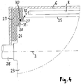
- FIG. 2 For example, a radiation shield for the arcuate nip according to embodiments of the invention is shown.
- a longitudinal section through the roller 2 is shown, wherein the section passes through the axis of rotation 3 therethrough.
- an electron beam 8 can be seen.
- the roller 2 is driven by a drive shaft 13, which sets the roller 2 about the rotation axis 3 in rotating motion.
- the roller 2 has an end face 14 which extends substantially perpendicular to the axis of rotation 3.
- the end face 14 is adjoined by a convexly curved, rotationally symmetrical transition region 15, which forms a curved transition between the end face 14 and the lateral surface 16.
- the front end profile 17 of the roller 2 comprises both the end face 14 and the curved transition region 15th
- a frontal shielding block 18 is releasably attached to the irradiation unit 6, which has a recess 19, wherein the front end profile 17 of the roller 2 extends into the recess 19.
- the inner surface of the recess 19 is complementary to the shape of the end face 14 and the curved transition region 15 is formed.
- a comparatively narrow gap region 20 is formed between the end-side end profile 17 and the recess 19 formed to be complementary thereto.
- the gap region 20 preferably has a gap width of more than 1 mm, more preferably more than 3 mm.
- the gap region 20 preferably has a gap width of less than 10 mm, more preferably less than 7 mm.
- the gap region 20 serves to shield the X-rays produced during the electron irradiation.
- the X-ray radiation enters the gap region 20 between the end-side shielding block 18 and the end-side end profile 17 in the direction of the arrow 21, the X-radiation inside the gap region 20 is refracted several times and thus attenuated so that no X-ray radiation can escape to the outside. In this case, a significant attenuation of the X-ray radiation is achieved in particular between the curved transition region 15 and the recess 19 formed in a complementary manner.
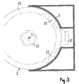
- FIG. 3 the roller 2 and the irradiation unit 6 are shown in cross section, wherein the shielding of the X-ray radiation according to the invention can be seen on the end face of the roller 2.
- the roller 2 In the cross section of FIG. 3 is the roller 2 with the drive shaft 13 and the To detect rotation axis 3. Also, in FIG. 3 to recognize the receptacle 7 and the at least one electron emitter 8, wherein the receptacle 7, the outer surface of the roller 2 partially encloses.
- an effective shielding of the X-ray radiation is achieved by the interaction of the convexly curved transition region 15 with the complementary concave curvature of the recess 19.
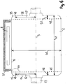
- FIG. 4 a roller 23 is shown in which a plurality of circumferential steps are provided in the transition region between the end face 24 and the lateral surface 25 for radiation shielding, for example, one, two, three or four circumferential steps.
- two circumferential steps are provided, a first circumferential step 26 and a second circumferential step 27.
- the roller 23 can rotate about the rotation axis 3, wherein the roller 23 is driven via the drive shaft 28.
- the irradiation unit 6 for radiation shielding comprises an end shielding block 29 with a stepped profile 30 which is complementary to the first peripheral step 26 and the second peripheral step 27 of the roller 23, so that the stepped profile 30 with the two peripheral steps 26 and 27 in Intervention is.
- a gap region 31 arises between the end-side end profile of the roller 23 and the shielding block 29 FIG. 4 it would appear that the X-radiation emitted in the direction of the arrow 32 could be completely shielded by the shielding block 29 and the roller 23.
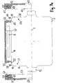
- the cross-sectional view of FIG. 5 shows, however, that this is not the case. In FIG.
- the roller 23 rotatable about the axis of rotation 3 is shown in cross-section, wherein the lateral surface of the roller 23 is partially enclosed by the receptacle 7.
- the arranged in the receptacle 7 at least one electron emitter 8 is adapted to generate electrons for irradiation of the guided over the roller 23 material web.
- high - energy x - ray radiation is generated, which, inter alia, can be found in the FIG. 5 dashed lines 33, 34, 35 and 36 is emitted.
- FIG. 6 shows a longitudinal section through the roller 2, which passes through the axis of rotation 3 therethrough.
- the roller 2 can be driven in rotation about the rotation axis 3 via the drive shaft 13.
- an irradiation unit 37 which comprises at least one electron emitter 8.
- the roller 2 has a first end region 14, to which a first curved transition region 15 connects.
- the first arched transitional region 15 forms a transition between the first frontal region 14 and the lateral surface 16 of the roller 2.
- the second frontal region 38 is provided opposite the first frontal region 14.
- the second arched transitional region 38 adjoins the second frontal region 38, which forms the transition between the second frontal region 38 and the lateral surface 16 of the roller 2.
- the lateral surface 16 is formed as a lateral surface of a circular cylinder of diameter D and is intended to guide the web material to be irradiated through the irradiation device.
- the diameter D is for example in the range between 15 cm and 155 cm.
- the diameter D of the roller 2 is represented by the double arrow 40.
- the length L of the roller 2 extends from the first end region 14 in the axial direction to the second end region 38.
- the length L may for example be in the range between 40 cm and 3.8 m.
- the length L is represented by the double arrow 41.
- the first end region 14 of the roller 2 has at its circular peripheral edge a radius R 1 , which is preferably in the range between 30% and 47% of the diameter D.
- the radius R 1 extends to the circular peripheral edge of the first frontal region 14.
- the radius R 1 is in FIG. 6 illustrated by the double arrow 42.
- the first end-side region 14 therefore already ends at the first radial position 43, at which the first arched transitional region 15 adjoins. In this case, the slope of the contour of the roller runs continuously at the transition from the first frontal area 14 to the first arched transitional area 15.
- r ⁇ denotes the radius of the circle of curvature.
- the predetermined maximum curvature ⁇ of the contour corresponds to a minimum radius of curvature r ⁇ .
- the minimum radius of curvature r ⁇ is preferably 5% of the diameter D.
- the radius of curvature at each point of the contour within the first arched transitional region 15 is above the minimum radius of curvature r ⁇ , which is 5% of the diameter D. More preferably, the radius of curvature at each point of the contour within the transition region 15 is in the range between 5% and 40% of the diameter D.
- the curvature is constant within the entire transition region, the curvature in the entire first transition region 15 being given by the radius of curvature of the circle 44 drawn with dashed lines.
- the curvature varies within the transition region 15, wherein at each point a maximum curvature must not be exceeded or a minimum radius of curvature r ⁇ must not be fallen below.
- the lateral surface 16 adjoins the first transition region 15, wherein the slope of the contour at the transition to the lateral surface 16 and in particular at the first axial position 45 is continuous.
- the first axial position 45 relative to the edge of the first end region 14 in the axial Direction offset by a distance L1 to the center of the roller 2, wherein the distance L1 is preferably between 3% and 25% of the length L.
- the distance L1 of the first axial position 45 in the axial direction relative to the first end region 14 is illustrated by the double arrow 46.
- the profile of the contour of the roller 2 at the second axial end of the roller 2 corresponds to the contour of the contour at the first axial end of the roller 2.
- the contour at the second axial end of the roller 2 but also from the contour at the first axial end differentiate the roller 2.
- the second frontal region 38 preferably has at its circular peripheral edge a radius R 2 , which lies in the range between 30% and 47% of the diameter D. In FIG. 6 the radius R 2 is represented by the double arrow 47.
- the second end-side region 38 only extends to the second radial position 48.
- the second arched transitional region 39 adjoins the second end region 38, wherein the gradient at the transition between the second end region 38 and the second arched transition region 39 is continuous .
- the curvature ⁇ is smaller than a maximum curvature, which is obtained as the reciprocal of a minimum radius of curvature r K.
- the minimum radius of curvature r ⁇ is preferably 5% of the diameter D.
- the curvature within the second transitional region 39 is in a range that corresponds to a radius of curvature between 5% and 40% of the diameter D.
- the curvature can be as in the FIG. 6 be shown at each point of the second transition region 39 by a constant radius of curvature. However, the curvature may also vary within the second transition region 39, wherein the curvature at each point must be less than a predetermined maximum curvature in order to avoid sharp edges in the course of the contour of the roller 2 in the second transition region 39.
- the second transition region 39 merges into the lateral surface 16, wherein the slope at the transition between the second transition region 39 and the lateral surface 16 runs continuously.
- the slope of the contour of the roller 2 in a longitudinal plane through the central axis 3 viewed at the transition from the second end region 38 to the second curved transition region 39, within the second curved transition region 39 and at the transition from the second curved transition region 39 to the lateral surface 16 each steadily.
- the second axial position 49 is opposite to the second end region 38 of FIG Roller 2 offset in the axial direction by a distance L2 to the center of the roller 2, wherein the distance L2 is preferably in the range between 3% and 25% of the length L of the roller 2.
- the distance L2 is represented by the double arrow 50.
- the diameter of the outer contour of the roller remains the same or becomes smaller.
- the diameter of the outer contour of the roller remains the same or becomes smaller in the axial direction.
- each shielding 51, 52 are releasably attached.
- the Ableblöcke 51, 52 of the arcuate gap between the irradiation unit 37 and the roller 2 at the two end faces is shielded so that the resulting X-ray radiation is effectively retained.
- Shielding block 51 is shown in an oblique view.
- the recess 53 which is formed as a negative mold to at least a part of the front end profile 17 of the roller 2.
- the inner surface of the recess 53 is complementary to the end face 14 and the curved transition region 15 is formed.
- the recess 53 has a circumferential concave curvature, which is complementary to the convexly outwardly curved transition region 15 of the roller 2 is formed.
- the shielding block 51 has a bearing surface 54, which is intended to be releasably secured to the frontal mounting surface 55 of the irradiation unit 37.
- the front-side mounting surface 55 of the irradiation unit 37 preferably extends in a direction substantially perpendicular to the axis of rotation of the roller 2 level.
- the front-side mounting surface 55 could also extend in a plane inclined relative to the center axis 3.
- the front-side mounting surface 55 could extend in a plane which is inclined relative to a plane perpendicular to the center axis 3 by an angle between 0 ° and 60 °.
- the support surface 54 of the Ableblocks 51 would extend in a plane inclined to the center axis 3 level.
- the gap region has a substantially uniform gap width.
- the releasable attachment of the shielding block 51 on the front-side mounting surface 55 of the irradiation unit 37 is preferably carried out by means provided for this purpose fasteners 56, for example by means of dowel pins, screw, clamping elements or other fasteners.
- the fastening elements 56 may be provided, for example, to fix the shielding block 51 in a position in which the bearing surface 54 rests on the frontal mounting surface 55.
- the support surface 54 is flat on the front-side mounting surface 55.
- the fastening elements 56 may be configured to allow an adjustable positioning of the shielding block 51 relative to the irradiation unit 37 in order to be able to adjust, for example, the gap area between the recess 53 and the frontal end profile 17.
- the adjustment of the position of the Ableblocks 51 relative to the irradiation unit 37 by means of the fasteners 56 may include at least one of: a positioning of the Ableblocks 51 in the axial direction, a positioning of the Ableblocks 51 in a direction perpendicular to the axial direction or oblique plane, an adjustment of Inclination of the shielding block 51 relative to a transverse plane to the center axis 3.
- the shielding block 51 can be positioned by means of the fastening elements 56 so that a desired gap region results between the recess 53 and the end-side end profile 17, for example a homogeneously formed gap region of uniform gap width. Additionally or alternatively, by adjusting the position of the shielding block 51, the gap width of the gap region can be adjusted.
- a recess 57 running around a part of the roller 2 is provided into which one or more arcuate plates 58 can be inserted.
- the arcuate plates 58 inserted into the recess 57 extend as far as the surface of the roller 2 and thus effect a gas-tight or at least approximately gas-tight seal between the region of the roller 2 irradiated by the at least one electron emitter 8 and the gap region which exists between the shielding block 51 and the front end profile 17 of the roller 2 is formed.
- a vacuum are generated in the gap region between the shielding block 51 and the front end profile 17 of the roller 2.
- ozone is formed.
- the gas seal prevents the ozone from escaping outside.
- a noble gas such as argon can be introduced into the gap region between the at least one electron emitter 8 and the lateral surface 16.
- the introduced inert gas by means of the arcuate metal sheets 58 in the gap region between the at least one electron emitter 8 and the lateral surface 16 held.
- the arcuate plates 58 may preferably be formed as segments of a circular ring, for example in the form of a semicircle covering sheet. In this case, an arcuate plate, for example, from two or more adjacent to each other arranged circular arc segments are assembled.
- recesses 59 may be provided within the shielding block, in which inserts 60 are made of radiation-absorbing material.
- molten shielding material such as molten lead
- the inserts 60 provide an efficient additional radiation shield with a small amount of radiation-absorbing material, which in particular absorbs the radiation emerging from the arcuate gap between the irradiation unit 37 and the roller 2.
- the shielding block 51 could for example be constructed of a plurality of superimposed plates, each having recesses for inserts of radiation-absorbing material. With such a construction of the multiple-plate shielding block 51, the recesses for the inserts may be formed on or in the bearing surfaces of the plates so that the inserts of radiation-absorbing material are located inside the shielding block 51.
- the second shielding block 52 is detachably mounted, wherein the bearing surface 61 of the second shielding block 52 at the Front-side mounting surface 62 of the irradiation unit 37 is releasably attached.
- the second end-side end profile 63 extends into the recess 64 of the second shielding block 52 and is at least partially enclosed by the recess 64.
- the front-side mounting surface 62 of the irradiation unit 37 is also provided around a part of the roller 2 circumferential recess 65, are used in the arcuate sheets 66 for gas sealing.
- the second shielding block 52 also has recesses 67 in which inserts 68 of radiation-shielding material, such as lead, can be inserted.
- FIG. 7b the irradiation device is shown in the assembled state, wherein the shielding block 51 is releasably secured with its support surface 54 on the front-side mounting surface 55 of the irradiation unit 37 and wherein the shielding block 52 is releasably secured with its support surface 64 on the front-side mounting surface 62.
- the shielding blocks 51, 52 extend from the at least one electron emitter 8 up to the axis of rotation 3, recesses 69 for the drive shaft 13 being provided in each of the shielding blocks 51, 52.
- the shielding block 51 preferably covers at least 30%, more preferably at least 40%, more preferably at least 50%, more preferably at least 55%, more preferably at least 60% of the end face or cross-sectional area of the roll 2, as viewed in the direction of the rotation axis 3.
- the shielding block 51 covers less than 80%, more preferably less than 70%, more preferably less than 65% of the end face or cross-sectional area of the roll 2. In this way, an effective shielding of the X-radiation is achieved, wherein the accessibility of the roller 2 is further ensured in the open roller assembly.
Landscapes
- Engineering & Computer Science (AREA)
- General Engineering & Computer Science (AREA)
- Physics & Mathematics (AREA)
- High Energy & Nuclear Physics (AREA)
- Mechanical Engineering (AREA)
- Treatments Of Macromolecular Shaped Articles (AREA)
- Shaping Of Tube Ends By Bending Or Straightening (AREA)
- Physical Or Chemical Processes And Apparatus (AREA)
Applications Claiming Priority (1)
| Application Number | Priority Date | Filing Date | Title |
|---|---|---|---|
| DE102018003002.5A DE102018003002B4 (de) | 2018-04-12 | 2018-04-12 | Bahnführungswalze mit stirnseitiger Strahlungsabschirmung sowie Bestrahlungsvorrichtung |
Publications (1)
| Publication Number | Publication Date |
|---|---|
| EP3557591A1 true EP3557591A1 (fr) | 2019-10-23 |
Family
ID=66217657
Family Applications (1)
| Application Number | Title | Priority Date | Filing Date |
|---|---|---|---|
| EP19000182.6A Pending EP3557591A1 (fr) | 2018-04-12 | 2019-04-12 | Rouleau de guidage de bande à protection frontale contre le rayonnement ainsi que dispositif de rayonnement |
Country Status (3)
| Country | Link |
|---|---|
| US (1) | US20190315589A1 (fr) |
| EP (1) | EP3557591A1 (fr) |
| DE (1) | DE102018003002B4 (fr) |
Citations (2)
| Publication number | Priority date | Publication date | Assignee | Title |
|---|---|---|---|---|
| JP2004077235A (ja) * | 2002-08-14 | 2004-03-11 | Toyo Ink Mfg Co Ltd | 活性エネルギー線照射装置および放射線遮蔽構造 |
| US20100230618A1 (en) * | 2009-03-10 | 2010-09-16 | John Drenter | Electron beam web irradiation apparatus and process |
Family Cites Families (5)
| Publication number | Priority date | Publication date | Assignee | Title |
|---|---|---|---|---|
| DE10014563A1 (de) * | 2000-03-23 | 2001-10-04 | Beiersdorf Ag | Elektronenstrahl-Vernetzung von Haftklebemassen |
| DE10163490B4 (de) * | 2001-12-21 | 2008-07-10 | Tesa Ag | Verfahren zur Vernetzung von bahnförmigem, sich auf einem Release-Liner befindlichen Material mittels Elektronenstrahlen |
| DE102004048881A1 (de) | 2004-10-06 | 2006-04-13 | Tesa Ag | Verfahren zur Vernetzung einer Klebemasse, die sich auf einem beidseitig mit antiadhäsiven Silikonschichten ausgerüsteten Träger befindet, mittels Elektronenstrahlen |
| US20070231495A1 (en) * | 2006-03-31 | 2007-10-04 | Ciliske Scott L | Method of forming multi-layer films using corona treatments |
| DE102009001648A1 (de) * | 2009-03-19 | 2010-09-23 | Voith Patent Gmbh | Walze für eine Papiermaschine |
-
2018
- 2018-04-12 DE DE102018003002.5A patent/DE102018003002B4/de active Active
-
2019
- 2019-04-10 US US16/380,611 patent/US20190315589A1/en not_active Abandoned
- 2019-04-12 EP EP19000182.6A patent/EP3557591A1/fr active Pending
Patent Citations (2)
| Publication number | Priority date | Publication date | Assignee | Title |
|---|---|---|---|---|
| JP2004077235A (ja) * | 2002-08-14 | 2004-03-11 | Toyo Ink Mfg Co Ltd | 活性エネルギー線照射装置および放射線遮蔽構造 |
| US20100230618A1 (en) * | 2009-03-10 | 2010-09-16 | John Drenter | Electron beam web irradiation apparatus and process |
Also Published As
| Publication number | Publication date |
|---|---|
| US20190315589A1 (en) | 2019-10-17 |
| DE102018003002B4 (de) | 2020-09-10 |
| DE102018003002A1 (de) | 2019-10-17 |
Similar Documents
| Publication | Publication Date | Title |
|---|---|---|
| DE3851119T2 (de) | Mehrschicht-Kollimator. | |
| DE102014202330B3 (de) | Single Source DualEnergy mit zwei Filtern zur Röntgenspektrumsdifferenzierung bei Strahlerblenden mit Schlitzplatte | |
| DE2919529A1 (de) | Verfahren und vorrichtung zum abschirmen einer inertzonen-elektronenbestrahlung von sich bewegenden bahnmaterialien | |
| DE3689231T2 (de) | Röntgenstrahlquelle. | |
| DE2442009A1 (de) | Geraet zur untersuchung eines koerpers mittels durchdringender strahlung | |
| DE7901623U1 (de) | Röntgenröhre | |
| CH405514A (de) | Anordnung zum Richten einer ionisierenden Strahlung auf einen Teil eines zu bestrahlenden Objektes | |
| EP0371303A1 (fr) | Appareil d'actinothérapie | |
| DE2426343A1 (de) | Vorrichtung zur untersuchung von objekten mittels durchdringender strahlung | |
| DE202013105829U1 (de) | Stehwellen-Elektronenlinearbeschleuniger mit kontinuierlich regelbarer Energie | |
| DE1086429B (de) | Verfahren zum Bestrahlen eines organischen Polymers in kontinuierlicher Weise | |
| EP0357146A2 (fr) | Dispositif pour générer un faisceau de rayons X ou gamma de petite section transversale et de direction variable | |
| DE2727275C3 (de) | Elektronenbeschleuniger mit einem dem Elektronenstrahl ausgesetzten Target | |
| DE2900516A1 (de) | Vorrichtung zur erzeugung einer roentgenbremsstrahlung | |
| EP0021441B1 (fr) | Accélérateur d'électrons pour radiothérapie aux rayons X | |
| DE2530663A1 (de) | Einrichtung zur begrenzung eines strahlenbuendels hoher energie, insbesondere eines roentgenstrahlenbuendels | |
| DE2803347A1 (de) | Roentgenstrahlenquelle | |
| DE102013220189A1 (de) | Röntgenquelle und Verfahren zur Erzeugung von Röntgenstrahlung | |
| CH630176A5 (en) | Method of producing a tomogram and device for tomographically investigating an object | |
| DE2738165A1 (de) | Roentgenstrahlungsgenerator | |
| EP3557591A1 (fr) | Rouleau de guidage de bande à protection frontale contre le rayonnement ainsi que dispositif de rayonnement | |
| DE69000403T2 (de) | Oberflaechenbearbeitung mittels laser-energie. | |
| DE2655383A1 (de) | Zylindrischer reflektor mit ellipsenabschnittsfoermigem querschnitt | |
| DE202016100507U1 (de) | Laserschutzvorrichtung | |
| EP0536683B1 (fr) | Appareil de guidage d'un rayon laser |
Legal Events
| Date | Code | Title | Description |
|---|---|---|---|
| PUAI | Public reference made under article 153(3) epc to a published international application that has entered the european phase |
Free format text: ORIGINAL CODE: 0009012 |
|
| STAA | Information on the status of an ep patent application or granted ep patent |
Free format text: STATUS: THE APPLICATION HAS BEEN PUBLISHED |
|
| AK | Designated contracting states |
Kind code of ref document: A1 Designated state(s): AL AT BE BG CH CY CZ DE DK EE ES FI FR GB GR HR HU IE IS IT LI LT LU LV MC MK MT NL NO PL PT RO RS SE SI SK SM TR |
|
| AX | Request for extension of the european patent |
Extension state: BA ME |
|
| STAA | Information on the status of an ep patent application or granted ep patent |
Free format text: STATUS: REQUEST FOR EXAMINATION WAS MADE |
|
| 17P | Request for examination filed |
Effective date: 20200504 |
|
| RBV | Designated contracting states (corrected) |
Designated state(s): AL AT BE BG CH CY CZ DE DK EE ES FI FR GB GR HR HU IE IS IT LI LT LU LV MC MK MT NL NO PL PT RO RS SE SI SK SM TR |