EP3557540B1 - Valuable medium processing apparatus and valuable medium processing method - Google Patents
Valuable medium processing apparatus and valuable medium processing method Download PDFInfo
- Publication number
- EP3557540B1 EP3557540B1 EP19165119.9A EP19165119A EP3557540B1 EP 3557540 B1 EP3557540 B1 EP 3557540B1 EP 19165119 A EP19165119 A EP 19165119A EP 3557540 B1 EP3557540 B1 EP 3557540B1
- Authority
- EP
- European Patent Office
- Prior art keywords
- information
- mounting
- frame
- section
- storage bag
- Prior art date
- Legal status (The legal status is an assumption and is not a legal conclusion. Google has not performed a legal analysis and makes no representation as to the accuracy of the status listed.)
- Active
Links
Images


Classifications
-
- G—PHYSICS
- G07—CHECKING-DEVICES
- G07D—HANDLING OF COINS OR VALUABLE PAPERS, e.g. TESTING, SORTING BY DENOMINATIONS, COUNTING, DISPENSING, CHANGING OR DEPOSITING
- G07D11/00—Devices accepting coins; Devices accepting, dispensing, sorting or counting valuable papers
- G07D11/20—Controlling or monitoring the operation of devices; Data handling
- G07D11/22—Means for sensing or detection
- G07D11/235—Means for sensing or detection for monitoring or indicating operating conditions; for detecting malfunctions
-
- G—PHYSICS
- G07—CHECKING-DEVICES
- G07D—HANDLING OF COINS OR VALUABLE PAPERS, e.g. TESTING, SORTING BY DENOMINATIONS, COUNTING, DISPENSING, CHANGING OR DEPOSITING
- G07D11/00—Devices accepting coins; Devices accepting, dispensing, sorting or counting valuable papers
- G07D11/009—Depositing devices
-
- G—PHYSICS
- G06—COMPUTING OR CALCULATING; COUNTING
- G06K—GRAPHICAL DATA READING; PRESENTATION OF DATA; RECORD CARRIERS; HANDLING RECORD CARRIERS
- G06K7/00—Methods or arrangements for sensing record carriers, e.g. for reading patterns
- G06K7/10—Methods or arrangements for sensing record carriers, e.g. for reading patterns by electromagnetic radiation, e.g. optical sensing; by corpuscular radiation
- G06K7/14—Methods or arrangements for sensing record carriers, e.g. for reading patterns by electromagnetic radiation, e.g. optical sensing; by corpuscular radiation using light without selection of wavelength, e.g. sensing reflected white light
- G06K7/1404—Methods for optical code recognition
- G06K7/1408—Methods for optical code recognition the method being specifically adapted for the type of code
-
- G—PHYSICS
- G07—CHECKING-DEVICES
- G07D—HANDLING OF COINS OR VALUABLE PAPERS, e.g. TESTING, SORTING BY DENOMINATIONS, COUNTING, DISPENSING, CHANGING OR DEPOSITING
- G07D11/00—Devices accepting coins; Devices accepting, dispensing, sorting or counting valuable papers
- G07D11/10—Mechanical details
- G07D11/12—Containers for valuable papers
- G07D11/125—Secure containers
-
- G—PHYSICS
- G07—CHECKING-DEVICES
- G07D—HANDLING OF COINS OR VALUABLE PAPERS, e.g. TESTING, SORTING BY DENOMINATIONS, COUNTING, DISPENSING, CHANGING OR DEPOSITING
- G07D11/00—Devices accepting coins; Devices accepting, dispensing, sorting or counting valuable papers
- G07D11/10—Mechanical details
- G07D11/14—Inlet or outlet ports
-
- G—PHYSICS
- G07—CHECKING-DEVICES
- G07D—HANDLING OF COINS OR VALUABLE PAPERS, e.g. TESTING, SORTING BY DENOMINATIONS, COUNTING, DISPENSING, CHANGING OR DEPOSITING
- G07D11/00—Devices accepting coins; Devices accepting, dispensing, sorting or counting valuable papers
- G07D11/20—Controlling or monitoring the operation of devices; Data handling
- G07D11/24—Managing the inventory of valuable papers
-
- G—PHYSICS
- G07—CHECKING-DEVICES
- G07D—HANDLING OF COINS OR VALUABLE PAPERS, e.g. TESTING, SORTING BY DENOMINATIONS, COUNTING, DISPENSING, CHANGING OR DEPOSITING
- G07D11/00—Devices accepting coins; Devices accepting, dispensing, sorting or counting valuable papers
- G07D11/20—Controlling or monitoring the operation of devices; Data handling
- G07D11/30—Tracking or tracing valuable papers or cassettes
-
- G—PHYSICS
- G07—CHECKING-DEVICES
- G07D—HANDLING OF COINS OR VALUABLE PAPERS, e.g. TESTING, SORTING BY DENOMINATIONS, COUNTING, DISPENSING, CHANGING OR DEPOSITING
- G07D11/00—Devices accepting coins; Devices accepting, dispensing, sorting or counting valuable papers
- G07D11/20—Controlling or monitoring the operation of devices; Data handling
- G07D11/32—Record keeping
- G07D11/34—Monitoring the contents of devices, e.g. the number of stored valuable papers
-
- G—PHYSICS
- G07—CHECKING-DEVICES
- G07D—HANDLING OF COINS OR VALUABLE PAPERS, e.g. TESTING, SORTING BY DENOMINATIONS, COUNTING, DISPENSING, CHANGING OR DEPOSITING
- G07D11/00—Devices accepting coins; Devices accepting, dispensing, sorting or counting valuable papers
- G07D11/40—Device architecture, e.g. modular construction
Definitions
- the present invention relates to a valuable medium processing apparatus, an information processing apparatus, a valuable medium processing system, and a valuable medium processing method.
- the Japanese Patent Application Laid-Open No. 2016-146142 discloses a banknote storage mechanism that stores a banknote in a storage bag such as a pouch bag. Additionally, PTL 1 discloses that regulation of access to storage bags prevents a storage bag other than a storage bag to be retrieved from being detached from a mounting section to be retrieved, and anti-theft property is enhanced.
- the GB 2 325 327 A describes a currency monitoring apparatus comprising a scanner provided at a currency receipt point for scanning a tendered bank note which, if recognized as being genuine, is passed to a security bag contained in a strongbox.
- a record is maintained by a control computer of the serial number of the security bag associated with the currency receipt point at any given time, the data being input to the control computer manually or by scanning the barcode on the security bag.
- the document JP 2015 060290 A describes a banknote teller machine which is provided with a banknote cassette that is mounted in a slot and stores banknotes in accordance with the denomination thereof, a control unit that dispenses banknotes from the banknote cassette and determines the denomination thereof; and a storage unit that stores the denomination of the banknotes as determined by the control unit.
- the document US 2013/213763 A1 describes a cash management safe including a bill validator and stacker and a bagging mechanism for sealing received bills in a tamper evident bag prior to allowing the safe to be opened.
- a storage bag a is set in a mounting section A of a banknote processing apparatus
- a storage bag b is set in a mounting section B of the banknote processing apparatus.
- respective inventory amounts of banknotes stored in the storage bags a, b, and the inventory amounts of the storage bags a, b, each data of which is managed by the apparatus are sometimes wrongly exchanged.
- An object of the present invention is to provide a technology capable of suppressing a mounting error to a valuable medium processing apparatus for a storage bag.
- a valuable medium processing apparatus of the present invention comprises the features of the independent claim 1.
- a valuable medium processing method of the present invention comprises the features of the independent claim 15.
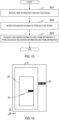
- FIG. 1 is a schematic configuration diagram of a banknote processing apparatus 1 according to Embodiment 1.
- the banknote processing apparatus 1 has an inlet section 2, a transport unit 3, a recognition unit 4, a storing/feeding unit 5, an ejection section 6, frames 7, 8, an operation display 9, a bar code reader 10, and a control section 30.
- FIG. 1 also illustrates storage bags 21, 22 mounted on the frames 7, 8.
- the banknote processing apparatus 1 illustrated in FIG. 1 is installed in, for example, a shop such as a supermarket, a bank or the like, and performs various processes such as a money reception/payment process.
- a rectangular coordinate system of x-, y-, z-axes illustrated in FIG. 1 is set to the banknote processing apparatus 1.
- Banknotes are input in the inlet section 2 by a user.
- the inlet section 2 has a feeding mechanism section 2a.
- the inlet section 2 feeds out the banknotes input by the user to the transport unit 3 one by one by using the feeding mechanism section 2a.
- the recognition unit 4 is provided in the periphery of the transport unit 3 on a downstream side of the inlet section 2 and on an upstream side of the storing/feeding unit 5, the ejection section 6, and the frames 7, 8.
- the recognition unit 4 includes various sensors (not illustrated), and recognizes denomination, genuineness, face/back, fitness, new/old, and the like of banknotes to be transported by the transport unit 3.
- the banknotes to be transported by the transport unit 3 are transported to any of the storing/feeding unit 5, the ejection section 6, and the frames 7, 8 (storage bags 21, 22) in accordance with a recognition result of the recognition unit 4, operation of the user, or the like.
- the storing/feeding unit 5 includes a so-called winding type banknote storing/feeding mechanism.
- the storing/feeding unit 5 temporarily stores the banknotes transported by the transport unit 3, and feeds out the temporarily stored banknotes to the transport unit 3.
- the banknotes transported from the transport unit 3 are accumulated in the ejection section 6.
- the ejection section 6 has a stacking wheel driving section 6a that rotates a stacking wheel.
- the ejection section 6 arrays and accumulates the banknotes transported from the transport unit 3, by the rotating stacking wheel. The user can take out the banknotes accumulated in the ejection section 6, from a front surface of the banknote processing apparatus 1.
- the frame 7 has mounting sections 7aa, 7ab, and stages 7ba, 7bb.
- the storage bag 21 is suspended between the mounting sections 7aa, 7ab.
- the storage bag 21 is suspended between the mounting sections 7aa, 7ab in a state in which an opening is open.
- the banknotes to be transported by the transport unit 3 are stored in the storage bag 21 with the opening being open.
- the stage 7ba moves toward the stage 7bb in accordance with control of the control section 30 described below.
- An upper part of the storage bag 21 is closed by movement of the stage 7ba to the stage 7bb (refer to FIG. 5 ).
- the frame 8 has mounting sections 8aa, 8ab, and stages 8ba, 8bb.
- the storage bag 22 is suspended between the mounting sections 8aa, 8ab.
- the storage bag 22 is suspended between the mounting sections 8aa, 8ab in a state in which an opening is open.
- the banknotes to be transported by the transport unit 3 are stored in the storage bag 22 with the opening being open.
- the stage 8ba moves toward the stage 8bb in accordance with control of the control section 30 described below.
- An upper part of the storage bag 22 is closed by movement of the stage 8ba to the stage 8bb (refer to FIG. 5 ).
- the operation display 9 is, for example, a touch panel.
- the operation display 9 displays various information related to the banknote processing apparatus 1. For example, the operation display 9 displays information related to a processing status of the money reception/payment process of banknotes, the inventory amount of banknotes stored in the storage bags 21, 22, and the like. Additionally, the operation display 9 receives user's operation, and transmits the information of the received user's operation to the control section 30.
- the bar code reader 10 reads a bar code.
- the bar code reader 10 transmits the information of the read bar code to the control section 30.
- the number of the frames may be three or more. That is, in the banknote processing apparatus 1, three or more storage bags may be mounted, and banknotes may be stored in respective storage bags.
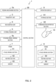
- FIG. 2 is a diagram illustrating a block configuration example of a control system of the banknote processing apparatus 1.
- FIG. 2 components identical to the components of FIG. 1 are denoted by the same reference numerals.
- the feeding mechanism section 2a, the transport unit 3, the recognition unit 4, the storing/feeding unit 5, the stacking wheel driving section 6a, the frames 7, 8, and the operation display 9 illustrated in FIG. 1 are connected to the control section 30.
- a storage section 61 and a communication interface section 62, which are not illustrated in FIG. 1 are connected to the control section 30.
- the control section 30 is composed of, for example, a CPU (Central Processing Unit), and controls the connected respective sections.
- the frame 7 has a stage driving section 41, a heating section 42, and a sensor 43.
- the frame 8 has a stage driving section 51, a heating section 52, and a sensor 53.
- the stage driving sections 41, 51, the heating sections 42, 52, and the sensors 43, 53 will be hereinafter described in detail.
- a program to be operated by the control section 30 is stored in the storage section 61. Additionally, data for performing a calculation process by the control section 30, data for controlling the connected respective sections, and the like are stored in the storage section 61.
- the bar code reader 10 is connected to the communication interface section 62.
- the control section 30 communicates with the bar code reader 10 through the communication interface section 62.
- the bar code reader 10 may be detachable from the communication interface section 62.
- a host apparatus (not illustrated) is connected to the communication interface section 62 through, for example, the Internet.
- the control section 30 communicates with the host apparatus through the communication interface section 62.
- the control section 30 transmits the information of the inventory amount of the banknote processing apparatus 1 or the like through the communication interface section 62.
- bar codes for recognizing the storage bags 21, 22 are attached to the storage bags 21, 22.
- the communication interface section 62 receives recognition information indicating the bar codes of the storage bags 21, 22, the bar codes being read by the bar code reader 10.
- the control section 30 acquires frame information of the frames 7, 8 (information for recognizing the frames 7, 8) to which the storage bags 21, 22 with the recognition information attached thereto are mounted, the recognition information being received by the communication interface section 62, and associates the acquired frame information, with the recognition information received by the communication interface section 62.
- the control section 30 stores the associated information in the storage section 61.
- FIG. 3 is a perspective view of the storage bag 21.
- the storage bag 21 has holes 71a to 71c, and 72a to 72c in an upper part.
- An interval between the holes 71a, 71b, and an interval between the holes 71b, 71c are different, and the interval between the holes 71a, 71b is larger than the interval between the holes 71b, 71c.
- the interval between the holes 71a, 71b is the same (including substantially the same) as an interval between the holes 72a, 72b facing the holes 71a, 71b.
- the interval between the holes 71b, 71c, and an interval between the holes 72b, 72c facing the holes 71b, 71c are the same.
- the storage bag 21 is a bag using, for example, polyethylene as a material.
- the storage bag 21 has an opening in an upper part. Banknotes transported by the transport unit 3 are stored from the opening of the storage bag 21.
- a bar code 73 is printed on the storage bag 21.
- the bar code 73 indicates recognition information for recognizing the storage bag 21.
- the recognition information may be, for example, a serial number of the storage bag 21.
- the bar code 73 may be printed on both sides of the storage bag 21.
- the storage bag 22 also has a configuration similar to the storage bag 21 illustrated in FIG. 3 , and has holes. Additionally, a bar code is printed on the storage bag 22, similarly to the storage bag 21. The bar code printed on the storage bag 22 is recognition information for recognizing the storage bag 22, and indicates the recognition information different from the bar code 73 of the storage bag 21.
- FIG. 4 is a perspective view of the mounting sections 7aa, 7ab and the stages 7ba, 7bb of the frame 7 of FIG. 1 .
- the mounting section 7aa has pins (projections) 81a to 81c on an upper surface.
- the mounting section 7ab has pins 82a to 82c on an upper surface.
- the mounting sections 7aa, 7ab are disposed on the same horizontal plane (on an xy plane), and is fixed to the frame 7.
- An interval between the pins 81a, 81b, and an interval between the pins 81b, 81c are different, and the interval between the pins 81a, 81b is larger than the interval between the pins 81b, 81c. Additionally, the interval between the pins 81a, 81b, and an interval between the pins 82a, 82b facing the pins 81a, 81b are the same. The interval between the pins 81b, 81c, and an interval between the pins 82b, 82c facing the pins 81b, 81c are the same.
- the holes 71a to 71c provided in the storage bag 21 are engaged with the pins 81a to 81c, respectively.
- the holes 72a to 72c provided in the storage bag 21 are engaged with the pins 82a to 82c, respectively. Consequently, the storage bag 21 is suspended between the mounting sections 7aa, 7ab, and is mounted on the frame 7 as illustrated in FIG. 1 .
- Intervals between the pins 81a to 81c, 82a to 82c of the mounting sections 7aa, 71ab are configured as illustrated in FIG. 4
- intervals between the holes 71a to 71c, 72a to 72c of the storage bag 21 are configured as illustrated in FIG. 3 .
- the bar code 73 of the storage bag 21 is directed in the +y-axis direction.
- the storage bag 21 is not mounted such that the bar code 73 is directed in the -y-axis direction. That is, the storage bag 21 is mounted such that the bar code 73 is directed in the predetermined orientation.
- the mounting section 7ab has the sensor 43 on such a surface as to face the mounting section 7aa.
- the sensor 43 detects the storage bag 21 being mounted on the mounting sections 7aa, 7ab. For example, light is shielded by mounting the storage bag 21 on the mounting sections 7aa, 7ab, so that the sensor 43 is an optical sensor that detects the storage bag 21 being mounted.
- a detection signal indicating that the storage bag 21 is mounted on the frame 7 is transmitted to the control section 30.
- the stage 7ba is provided in the frame 7 so as to be movable in the ⁇ y-axis direction.
- the stage 7bb is fixed to the frame 7.
- the stage 7ba is moved in the ⁇ y-axis direction by the stage driving section 41.
- the stages 7ba, 7bb are disposed on the same horizontal plane (on the xy plane).
- the stage 7ba moves in the -y-axis direction, the stage 7ba comes into contact with the stage 7bb.
- the stage 7ba moves to (is disposed at) a position separated from the stage 7bb (moves at a position illustrated in FIG. 1 or FIG. 4 ).
- the stage 7ba moves toward the stage 7bb. Consequently, the opening of the storage bag 21 is closed.
- FIG. 5 is a diagram illustrating a state in which the opening of the storage bag 21 is closed.
- components identical with the components in FIG. 1 and FIG. 4 are denoted by the same reference numerals.
- illustration of the pins 81a to 81c, 82a to 82c illustrated in FIG. 4 is omitted.
- banknotes P1 stored in the storage bag 21 are illustrated.
- the stage 7ba is moved toward the stage 7bb by the stage driving section 41 (moved in the -y-axis direction). For example, when the banknotes P1 are retrieved from the banknote processing apparatus 1, the stage 7ba moves toward the stage 7bb. The opening of the storage bag 21 is closed by the movement of the stage 7ba as illustrated in FIG. 5 .
- the stage 7ba has the heating section 42 such as a heater therein.
- the heating section 42 heats such a surface of the stage 7ba as to face the stage 7bb.
- the heating section 42 increases a temperature by control of the control section 30.
- stage 7ba moves toward the stage 7bb in the above description, the present invention is not limited to this.
- the stage 7bb may move toward the stage 7ba. Additionally, the stage 7ba may move toward the stage 7bb, and the stage 7bb may move toward the stage 7ba.
- the sensor 43 is mounted on the mounting section 7ab in the above description, but may be mounted on the mounting section 7aa. Additionally, the sensor 43 may be mounted on each of both the mounting sections 7aa, 7ab. The sensor 43 only needs to be able to detect the storage bag 21 being mounted, and is not limited to the optical sensor.
- heating section 42 is provided in the stage 7ba in the above description, the present invention is not limited to this.
- the heating section 42 may be provided in the stage 7bb, or may be provided in each of both the stages 7ba, 7bb.
- the mounting sections 7aa, 7ab and the stages 7ba, 7bb of the frame 7 are described in the above description, and the mounting sections 8aa, 8ab and the stages 8ba, 8bb of the frame 8 are similarly configured.
- the mounting sections 8aa, 8ab also have pins for suspending the storage bag 22, similarly to the mounting sections 7aa, 7ab of the frame 7.
- the mounting section 8ab has a sensor 53 that detects the storage bag 22 being mounted.
- the stage 8ba is moved in the ⁇ y-axis direction by the stage driving section 51. Additionally, the stage 8ba has a heating section 52 therein.
- the sensor 43 is mounted on the mounting section 7ab of the frame 7, and is associated with the frame 7.
- the sensor 53 is mounted on the mounting section 8ab of the frame 8, and is associated with the frame 8. Accordingly, when a detection signal is output from the sensor 43, the control section 30 can determine that the storage bag is mounted on the frame 7. When a detection signal is output from the sensor 53, the control section 30 can determine that the storage bag is mounted on the frame 8.
- a frame (mounting section) to which a storage bag is mounted is previously determined. That is, a user has to mount a predetermined storage bag on a predetermined frame.
- the frames 7, 8 to which the storage bags 21, 22 are mounted are not previously determined, and a user may mount the storage bags 21, 22 on either the frames 7, 8. That is, in the banknote processing apparatus 1, the storage bags 21, 22 can be mounted on both the frames 7, 8, so that a mounting error of the storage bags 21, 22 on the frames 7, 8 is suppressed.
- recognition information indicated by the bar code 73 printed on the storage bag 21 is "123456789”. It is assumed that recognition information indicated by the bar code printed on the storage bag 22 is "987654321”. It is assumed that frame information of the frame 7 is "A”. It is assumed that frame information of the frame 8 is "B”.
- the storage bags 21, 22 are not mounted on the frames 7, 8.
- a user reads a bar code printed on one of the storage bags 21, 22 by use of the bar code reader 10.
- the user may read any of the bar codes of the storage bags 21, 22.
- the bar code reader 10 transmits the recognition information "123456789" indicated by the read bar code 73 to the control section 30.
- the user reads the bar code 73, and thereafter the storage bag 21, the bar code 73 of which is read, is mounted on one of the frames 7, 8.
- the user may mount the storage bag 21 on any of the frames 7, 8.
- the storage bag 21 is mounted on the frame 7 (mounting sections 7aa, 71ab of the frame 7).
- the sensor 43 provided in the mounting section 7ab of the frame 7 detects the storage bag 21 being mounted, and transmits a detection signal to the control section 30.
- control section 30 When the control section 30 receives the detection signal from the sensor 43, it is determined that the storage bag 21 of the recognition information "123456789” received from the bar code reader 10 is mounted on the frame 7 of the frame information "A”. Then, the control section 30 associates the recognition information "123456789” received from the bar code reader 10 with the frame information "A" of the frame 7, and stores the associated information in the storage section 61.
- FIG. 6 is a diagram illustrating a data configuration example of the storage section 61. As illustrated in FIG. 6 , the recognition information " 123456789" of the storage bag 21 read by the bar code reader 10, and the frame information "A" of the frame 7 to which the storage bag 21 are mounted are associated to be stored in the storage section 61.
- the user reads the bar code which is printed on another storage bag 22, and is not read, by use of the bar code reader 10.
- the bar code reader 10 transmits the recognition information "987654321" indicated by the read bar code to the control section 30.
- the user reads the bar code, and thereafter mounts the storage bag 22 on one of the frames 7, 8.
- the user has already mounted the storage bag 21 on the frame 7, and therefore mounts the storage bag 22 on the frame 8.
- the sensor 53 provided in the mounting section 8ab of the frame 8 detects the storage bag 22 being mounted, and transmits a detection signal to the control section 30.
- control section 30 When the control section 30 receives the detection signal from the sensor 53, the control section 30 determines that the storage bag 22 of the recognition information "987654321” received from the bar code reader 10 is mounted on the frame 8 of the frame information "B". Then, the control section 30 associates the recognition information "987654321” received from the bar code reader 10 with the frame information "B" of the frame 8, and stores the associated information in the storage section 61.
- FIG. 7 is a diagram illustrating a data configuration example of the storage section 61.
- the recognition information "987654321" of the storage bag 22 read by the bar code reader 10, and the frame information "B" of the frame 8 to which the storage bag 22 are mounted are associated to be stored in the storage section 61.
- the recognition information "123456789” illustrated in FIG. 7 , and the frame information "A” are the recognition information of the storage bag 21 first mounted on the frame 7, and the frame information of the frame 7.
- the storage bags 21, 22, the recognition information of each of which is read by the bar code reader 10 are mounted on any of a plurality of the frames 7, 8, and the sensors 43, 53 of the frames 7, 8 to which the storage bags 21, 22 are mounted transmit detection results of the storage bags 21, 22 being mounted on the control section 30.
- the control section 30 associates the frame information associated with the sensors 43, 53 that transmit the detection results, and the recognition information received by the communication interface section 62. Consequently, the storage bags 21, 22 may be mounted on any of the frames 7, 8, and the banknote processing apparatus 1 can suppress a mounting error of the storage bags 21, 22 to the frames 7, 8.
- the storage bag 21 is first mounted on the frame 7, and thereafter the storage bag 22 is mounted on the frame 8 in the above description, but the present invention is not limited to the order mentioned.
- the storage bag 22 may be first mounted on the frame 7, and thereafter the storage bag 21 may be mounted on the frame 8. Consequently, the recognition information of the storage bags 21, 22 mounted on the frames 7, 8, and the frame information of the frames 7, 8 to which the storage bags 21, 22 are mounted are associated to be stored in the storage section 61.
- the control section 30 can acquire the recognition information of the storage bag mounted on the frame 7, and the recognition information of the storage bag mounted on the frame 8 by, for example, reference of the storage section 61.
- the control section 30 can acquire, for example, the inventory amount of banknotes stored in the storage bag 21 and the inventory amount stored in the storage bag 22 on the basis of the acquired recognition information.
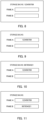
- FIG. 8 is Part 1 of a diagram illustrating a screen example displayed on an operation display 9. It is assumed that the user reads the bar code 73 printed on the storage bag 21 among the two storage bags 21, 22 by the bar code reader 10.
- the bar code reader 10 transmits the recognition information "123456789” indicated by the read bar code 73 to the control section 30.
- the control section 30 displays the recognition information "123456789” received from the bar code reader 10 on the operation display 9, as illustrated in "storage bag No.” of FIG. 8 .
- FIG. 9 is Part 2 of a diagram illustrating a screen example displayed on the operation display 9.
- the user reads the bar code 73 of the storage bag 21 by use of the bar code reader 10, the user mounts the storage bag 21, the bar code 73 of which is read, on one of the frames 7, 8.
- the user mounts the storage bag 21 on the frame 7.
- the sensor 43 of the frame 7 detects the storage bag 21 being mounted, and transmits a detection signal to the control section 30.
- the control section 30 determines that the storage bag 21 is mounted on the frame 7 of the frame information "A" by receiving of the detection signal from the sensor 43.
- the control section 30 displays the recognition information "123456789” of the storage bag 21 on a box corresponding to the frame A by the mounting determination of the storage bag 21 on the frame 7, as illustrated in the "frame A" of FIG. 9 . Consequently, when the user sees the operation display 9, for example, the user can recognize that the storage bag 21 of the recognition information "123456789" is mounted on the frame 7 of the frame information "A".
- a column of the "storage bag No.” illustrated in FIG. 9 becomes a blank by display (movement) of the frame A of the recognition information "123456789” in the box (refer to the "storage bag No.” of FIG. 8 ).
- the recognition information "123456789” of the storage bag 21 is displayed in a box corresponding to the frame B.
- FIG. 10 is Part 3 of a diagram illustrating a screen example displayed on the operation display 9.
- the user mounts the storage bag 21 on the frame 7, and thereafter reads the bar code of another storage bag 22 by use of the bar code reader 10.
- the bar code reader 10 transmits the recognition information "987654321" indicated by the read bar code to the control section 30.
- the control section 30 displays the recognition information "987654321" received from the bar code reader 10 on the operation display 9, as illustrated in the "storage bag No.” of FIG. 10 .
- FIG. 11 is Part 4 of a diagram illustrating a screen example displayed on the operation display 9.
- the user reads the bar code of the storage bag 22 by use of the bar code reader 10, the user mounts the storage bag 22, the bar code of which is read, on one of the frames 7, 8.
- the storage bag 21 has already mounted on the frame 7, and therefore the user mounts the storage bag 22 on the frame 8.
- the sensor 53 of the frame 8 detects the storage bag 22 being mounted, and transmits a detection signal to the control section 30.
- the control section 30 determines that the storage bag 22 is mounted on the frame 8 of the frame information "B", by receiving of the detection signal from the sensor 53.
- the control section 30 displays the recognition information "987654321” of the storage bag 22 in the box corresponding to the frame B by the mounting determination of the storage bag 22 on the frame 8, as illustrated in the "frame B" of FIG. 11 . Consequently, when the user sees the operation display 9, for example, the user can recognize that the storage bag 22 of the recognition information "987654321" is mounted on the frame 8 of the frame information "B".
- a column of the "storage bag No.” illustrated in FIG. 11 becomes a blank by display (movement) of the frame B of the recognition information "987654321" in the box (refer to the "storage bag No.” of FIG. 10 ).
- the control section 30 overwrites the recognition information "123456789" of the storage bag 21 received from the bar code reader 10 on the recognition information "987654321" of the storage bag 22. That is, in a case in which the control section 30 receives the recognition information of one of the storage bags 21, 22 from the bar code reader 10, and thereafter receives the recognition information of the other of the storage bags 21, 22 without receiving any detection signal from the sensors 43, 53, the latter recognition information is processed as an effective recognition information.
- the recognition information displayed on the "storage bag No.” of FIG. 8 is switched.
- the “123456789” is displayed in the "storage bag No.” of FIG. 8 .
- the " 123456789” displayed in the "storage bag No.” of FIG. 8 is switched to display of the "987654321".
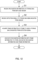
- FIG. 12 is a flowchart illustrating an operation example of the control section 30.
- the user reads the bar code of one of the storage bag 21 and the storage bag 22 by use of the bar code reader 10.
- the control section 30 receives the recognition information of the storage bag 21, 22 read by the bar code reader 10 from the bar code reader 10 (Step S1).
- the user After reading the bar code by use of the bar code reader 10, the user mounts the storage bag 21, 22, the bar code of which is read, on the frame 7, 8.
- the control section 30 receives a detection signal from the sensor 43, 53 of the frame 7, 8 (Step S2).
- the control section 30 acquires the frame information of the frame 7, 8 to which the storage bag 21, 22 is mounted, from the detection signal received in Step S2 (Step S3). For example, in a case in which the control section 30 receives the detection signal from the sensor 43, the control section 30 determines that the frame to which the storage bag 21, 22 is mounted is the frame 7, and acquires the frame information "A". On the other hand, in a case in which the control section 30 receives the detection signal from the sensor 53, the control section 30 determines that the frame to which the storage bag 21, 22 is mounted is the frame 8, and acquires the frame information "B".
- the control section 30 associates the recognition information received in Step S1 with the frame information acquired in Step S3 to store the associated recognition information and frame information in the storage section 61 (Step S4).
- control section 30 implements processes of Step S1 to S4.
- the banknote processing apparatus 1 that stores banknotes in the storage bags 21, 22 has a plurality of the frames 7, 8 to which a plurality of the storage bags 21, 22 are mounted, each the storage bags having the recognition information attached thereto, the recognition information for recognizing each storage bag, and the communication interface section 62 that receives the recognition information from the bar code reader 10 which reads the recognition information. Additionally, the banknote processing apparatus 1 has the control section 30 that acquires the frame information of the frames 7, 8 to which the storage bags 21, 22 each having the recognition information attached thereto are mounted, the recognition information being received by the communication interface section 62, and associates the acquired frame information with the recognition information received by the communication interface section 62. Consequently, the storage bags 21, 22 may be mounted on either the frames 7, 8, and the banknote processing apparatus 1 can suppress a mounting error of the storage bags 21, 22 to the frames 7, 8.
- the recognition information of each of the storage bags 21, 22 is read by the bar code reader 10 in the above description, the present invention is not limited to this.
- the recognition information indicated by numbers or the like is printed on a lower part of the bar code of each of the storage bags 21, 22, and the operation display 9 may receive this recognition information from a user.
- a bar code indicating frame information is attached to each of frames 7, 8.
- a control section 30 associates frame information attached to each of the frames 7, 8 with recognition information of each of storage bags 21, 22 mounted on the frames 7, 8 and stores the associated frame information and recognition information in a storage section 61.
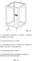
- FIG. 13 is a perspective view of a frame 7 according to Embodiment 2.
- illustration of mounting sections 7aa, 7ab and stages 7ba, 7bb is omitted.
- a bar code 91 indicating frame information "A" of the frame 7 is attached to the frame 7.
- a bar code indicating frame information "B" of the frame 8 is attached to the frame 8, similarly to the frame 7.
- FIG. 14 is a diagram illustrating an operation procedure example of a user.
- a user mounts the two storage bags 21, 22 on the frames 7, 8.
- the user may mount the two storage bags 21, 22 on either the frames 7, 8.
- the user When the user mounts the two storage bags 21, 22 on the frames 7, 8, the user reads one of the bar codes attached to the frames 7, 8 by use of a bar code reader 10.
- the user may first read either of the bar codes attached to the frames 7, 8.
- the user When the user reads the bar code of the frame 7, 8 by use of the bar code reader 10, the user reads the bar code of the storage bag 21, 22 mounted on the frame 7, 8, the bar code of which is read.
- the user reads the bar code 91 of the frame 7 by use of the bar code reader 10, and therefore reads the bar code 73 of the storage bag 21 mounted on the frame 7 (Step S13).
- the control section 30 associates the frame information of the frame 7 read in Step S12 with the recognition information of the storage bag 21 read in Step S13, and stores the associated frame information and recognition information in the storage section 61.
- the user reads the bar code of the other of the frames 7, 8, the bar code of which is not read, by use of the bar code reader 10.
- the user reads the bar code of the frame 7 in Step S12, and therefore reads the bar code of the frame 8 (Step S14).
- the user When the user reads the bar code of the frame 7, 8 by use of the bar code reader 10, the user reads the bar code of the storage bag 21, 22 mounted on the frame 7, 8, the bar code of which is read.
- the user reads the bar code of the frame 8 by use of the bar code reader 10 in Step S14, and therefore reads the bar code of the storage bag 22 mounted on the frame 8 (Step S15).
- the control section 30 associates the frame information of the frame 8 read in Step S14 with the recognition information of the storage bag 22 read in Step S15, and stores the associated frame information and recognition information in the storage section 61.
- FIG. 15 is a flowchart illustrating an operation example of the control section 30. It is assumed that the storage bags 21, 22 are mounted on the frames 7, 8 by a user.
- the user reads the bar code of one of the frames 7, 8 by use of the bar code reader 10.
- the control section 30 receives the frame information of the frame 7, 8 (one of the frames) read by the bar code reader 10, from the bar code reader 10 (Step S21).
- the user reads the bar code of the storage bag 21, 22 mounted on the frame 7, 8, the frame information of which is read, by use of the bar code reader 10.
- the control section 30 receives the recognition information of the storage bag 21, 22 read by the bar code reader 10, from the bar code reader 10 (Step S22).
- the control section 30 associates the frame information received in Step S21 with the recognition information received in Step S22, and stores the associated frame information and recognition information in storage section 61 (Step S23).
- control section 30 implements processes of Step S21 to S23.
- the frame information is attached to each of a plurality of the frames 7, 8, the communication interface section 62 receives the frame information from the bar code reader 10 that reads the frame information.
- the control section 30 associates the recognition information received by the communication interface section 62 with the frame information. Consequently, the storage bags 21, 22 may be mounted on either of the frames 7, 8, and the banknote processing apparatus 1 can suppress a mounting error of the storage bags 21, 22 to the frames 7, 8.
- Step S12, S13 of FIG. 14 may be reversed. Additionally, the order of the operation procedure of Step S14, S15 may be reversed. In this case, the order of the processes of Step S21, S22 of FIG. 15 is exchanged.
- the present invention is not limited to this.
- the user mounts one of the storage bags 21, 22 on one of the frames 7, 8, and thereafter reads the bar code of the storage bag 21, 22, and the bar code of the frame 7, 8 to which the storage bag 21, 22 is mounted. Thereafter, the user may mount the other of the storage bags 21, 22 on the other of the frame 7, 8 to which the storage bags 21, 22 are not mounted, and read the bar code of the storage bag 21, 22, and the bar code of the frame 7, 8 to which the storage bag 21, 22 is mounted.
- the frame information of each of the frames 7, 8 is read by the bar code, and therefore the mounting section 7ab, 8ab may not include the sensors 43, 53.
- the mounting section 7ab, 8ab may include the sensors 43, 53.
- the control section 30 can determine whether or not the storage bags 21, 22 are mounted on the frames 7, 8.
- the control section 30 may control such that bar code reading operation of the bar code reader 10 is enabled. That is, in a case in which the storage bags 21, 22 are not mounted on the frames 7, 8, the control section 30 may cause the bar code reader 10 not to read the bar code.
- control section 30 may not receive the recognition information to be transmitted from the bar code reader 10.
- the control section 30 may not receive the recognition information to be transmitted from the bar code reader 10.
- the control section 30 may store the recognition information and the frame information received from the bar code reader 10 in the storage section 61 so as to know the reception order. Then, the control section 30 may associate the recognition information with the frame information on the basis of the reception order of the recognition information and the frame information.
- the control section 30 combines the order of one of the frame information and the recognition information continuously stored, and the order of the other of the frame information and the recognition information continuously stored, and associates the frame information with the recognition information. That is, the control section 30 associates the frame information and the recognition information in such a manner that stored order of the frame information and stored order of the recognition information coincide with each other.
- the frame information of the frame 7 is stored in the storage section 61, and then the frame information of the frame 8 is stored.
- the recognition information of the storage bag 21 is stored in the storage section 61, and then the recognition information of the storage bag 22 is stored.
- the control section 30 associates the first stored frame information of the frame 7 among the frame information stored in the storage section 61 with the first stored recognition information of the storage bag 21 among the recognition information stored in the storage section 61.
- the control section 30 associates the second stored frame information of the frame 8 among the frame information stored in the storage section 61 with the second stored recognition information of the storage bag 22 among the recognition information stored in the storage section 61.
- the control section 30 may associate the frame information with the recognition information by utilizing the storage order in the storage section 61.
- the bar code reader 10 may collectively (simultaneously) read the bar code of the frame 7, and the bar code of the storage bag mounted on the frame 7. Then, the control section 30 may receive the collectively read frame information of the frame 7, and the recognition information of the storage bag mounted on the frame 7 through the communication interface section 62.
- the bar code reader 10 may collectively read the bar code of the frame 8 with the bar code of the storage bag mounted on the frame 8. Then, the control section 30 may receive the collectively read frame information of the frame 8, and the recognition information of the storage bag mounted on the frame 8 through the communication interface section 62. In this case, for example, erroneous operation of reading the bar code of the frame 7, and reading the bar code of the storage bag mounted on the frame 8 can be suppressed.
- the frame information of the frame 7 may be attached at such a position as to be collectively read along with the recognition information of the storage bag mounted on the frame 7, by the bar code reader 10.
- the frame information of the frame 8 may be attached at such a position as to be collectively read along with the recognition information of the storage bag mounted on the frame 8, by the bar code reader 10.
- the bar codes of the frames 7, 8 may be attached to the frames 7, 8 so as to be directed to the same orientation as the orientations to which the bar codes of the storage bags 21, 22 mounted on the frames 7, 8 are directed.
- FIG. 16 is a diagram illustrating the orientations of the bar code 91 of the frame 7 and the bar code 73 of the storage bag 21.
- the frame 7 and the storage bag 21 are illustrated.
- illustration of the mounting sections 7aa, 7ab and the stages 7ba, 7bb is omitted.
- a state in which the storage bag 21 is suspended is not illustrated.
- the bar code 73 of the storage bag 21 mounted on the frame 7 is printed on a surface directed in the +y-axis direction of the storage bag 21.
- the bar code 91 of the frame 7 is attached to such a surface as to be directed in the +y-axis direction of the frame 7. That is, the frame 7 has the bar code 91 attached to such a surface as to be directed in the same orientation as a surface to which the bar code 73 of the storage bag 21 is attached (surface directed in the +y-axis direction) when the storage bag 21 is mounted.
- the bar code 73 of the storage bag 21, and the bar code 91 of the frame 7 are directed in the same orientation (+y-axis direction), and therefore the bar code reader 10 can collectively read the bar code 73 of the storage bag 21, and the bar code 91 of the frame 7.
- the bar code 73 of the storage bag 21 may be printed on surfaces (both surfaces) directed in the ⁇ y-axis direction.
- the bar codes of the storage bags 21, 22 may be printed at places located directly below the stages 7ba, 7bb, 8ba, 8bb.
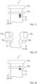
- FIG. 17 is a diagram illustrating an example of a printing position of the bar code 73 of the storage bag 21.
- FIG. 17 illustrates the mounting section 7aa and the stage 7ba of the frame 7, and a part of the storage bag 21.
- illustration of the pins 81a to 81c of the mounting section 7aa is omitted.
- the bar code 73 of the storage bag 21 is printed so as to be located directly below the stage 7ba.
- the bar code 73 is printed at a place located below by several centimeters (for example, 1 cm to 2 cm) from the stage 7ba.
- the bar code 73 is printed such that the long edge direction is parallel to the z-axis direction.
- FIG. 18 is a diagram illustrating an example in which the storage bag 21 is tucked up.
- FIG. 18 illustrates the mounting sections 7aa, 7ab and the stages 7ba, 7bb of the frame 7, and a part of the storage bag 21.
- illustration of the pins 81a to 81c, 82a to 82c of the mounting section 7aa is omitted.
- the storage bag 21 is tucked up near the stages 7ba, 7bb.
- the storage bag 21 is mounted on the frame 7 in a state of being tucked up, banknotes are not stored in the storage bag 21, and storage failure sometimes occurs.
- FIG. 19 is a diagram illustrating a state of the bar code 73 when the storage bag 21 is tucked up.
- components identical to the components of FIG. 17 are denoted by the same reference numeral.
- the bar code 73 printed directly below the stage 7ba is hidden behind the stage 7ba, as illustrated in FIG. 19 . Therefore, the user cannot read the bar code 73 of the storage bag 21 by use of the bar code reader 10.
- the banknote processing apparatus 1 can suitably store banknotes in the storage bag 21.
- the frame information may be attached to the frames 7, 8 such that the bar code reader 10 is directed in the readable direction (direction in which the user can read the bar code by use of the bar code reader 10).
- a door provided in front of the banknote processing apparatus 1 (for example, the banknote processing apparatus 1 viewed from the left toward the right in FIG. 1 ) is open, and the frames 7, 8 are taken out of the banknote processing apparatus 1 (taken out in the +y-axis direction).
- the frame information is attached such that the bar code reader 10 is directed in the readable direction of the frames 7, 8 taken out of the banknote processing apparatus 1.
- the frame information of the frame 7 is attached to the surface directed in the +y-axis direction of the frame 7, and the frame information of the frame 8 is attached to the surface directed in the -y-axis direction of the frame 8.
- the frames 7, 8 may have a mechanism for mounting the storage bags 21, 22 such that the bar codes of the storage bags 21, 22 are directed in the readable directions.
- the pins 81a to 81c of the mounting section 7aa of FIG. 4 , and the pins 82a to 82c of the mounting section 7ab are provided at positions different from each other.
- the mounting section 7aa rotates by 180 degrees
- the positions of the pins 81a to 81c of the mounting section 7aa are different from the positions of the pins 82a to 82c of the mounting section 7ab. Therefore, when the storage bag 21 illustrated in FIG. 3 is mounted on the mounting sections 7aa, 7ab illustrated in FIG. 4 , the bar code 73 is directed in the +y-axis direction. That is, the storage bag 21 illustrated in FIG. 3 is not mounted such that a surface having the bar code 73 attached thereto is directed in the -y-axis direction.
- the frame information of the frame 7 is attached to such a surface as to be directed in the +y-axis direction of the frame 7 so as to be readable from the +y-axis direction.
- the bar code 73 of the storage bag 21 is mounted so as to be directed in the +y-axis direction without being directed in the -y-axis direction. Consequently, the frame information of the frame 7, and the bar code 73 of the storage bag 21 are easily read from the +y-axis direction by the bar code reader 10.
- the mechanism in which the bar codes of the storage bags 21, 22 are directed in the readable directions is not limited to the above example.
- the number of the pins of the mounting section 7aa, and the number of the pins of the mounting section 7ab may be different from each other.
- the shapes of the pins of the mounting section 7aa, and the shapes of the pins of the mounting section 7ab may be different from each other.
- the control section 30 may notify a user that the other of the frame information and the recognition information is not read.
- the control section 30 may notify a user that the other of the frame information and the recognition information is not read by voice. Consequently, the user can collectively read the frame information and the recognition information again by use of the bar code reader 10.
- the control section 30 may notify a user that at least one of the frame information and the recognition information is not read.
- the recognition information of the storage bags 21, 22, and the frame information of the frames 7, 8 associated with the recognition information of the storage bags 21, 22 are stored in the storage section 61 in each of the above embodiments, but the present invention is not limited to this.
- the control section 30 may transmit the associated recognition information and frame information to the host apparatus through the communication interface section 62.
- the recognition information for recognizing each of the storage bags 21, 22 described in each of the above embodiment is not limited to the bar code.
- the recognition information for recognizing each of the storage bags 21, 22 may be a QR cord (registered trademark), a color cord, or the like.
- the frame information attached to each of the frames 7, 8 is not limited to the bar code, but may be a QR cord (registered trademark), a color cord, or the like.
- the association of the recognition information of the storage bags 21, 22, and the frame information of the frames 7, 8 described in each of the above embodiments may be performed by an information processing apparatus such as a PC (Personal Computer) and a server connected to the banknote processing apparatus 1.
- the information processing apparatus may have a function of the control section 30 illustrated in FIG. 2 , and receive the recognition information of the storage bags 21, 22 transmitted from the bar code reader 10, and the frame information of the frames 7, 8.
- the information processing apparatus may receive detection signals output by the sensors 43, 53. Then, the information processing apparatus may associate the recognition information of the storage bags 21, 22 with the frame information of the frames 7, 8, and store the associated recognition information and frame information in the storage section such as a memory.
- the host apparatus may have a function of the information processing apparatus.
Landscapes
- Physics & Mathematics (AREA)
- General Physics & Mathematics (AREA)
- Engineering & Computer Science (AREA)
- Health & Medical Sciences (AREA)
- Electromagnetism (AREA)
- General Health & Medical Sciences (AREA)
- Toxicology (AREA)
- Artificial Intelligence (AREA)
- Computer Vision & Pattern Recognition (AREA)
- Theoretical Computer Science (AREA)
- Cash Registers Or Receiving Machines (AREA)
- Inspection Of Paper Currency And Valuable Securities (AREA)
Description
- The present invention relates to a valuable medium processing apparatus, an information processing apparatus, a valuable medium processing system, and a valuable medium processing method.
- The
Japanese Patent Application Laid-Open No. 2016-146142 PTL 1 discloses that regulation of access to storage bags prevents a storage bag other than a storage bag to be retrieved from being detached from a mounting section to be retrieved, and anti-theft property is enhanced. - The
GB 2 325 327 A - The document
JP 2015 060290 A - The document
US 2013/213763 A1 describes a cash management safe including a bill validator and stacker and a bagging mechanism for sealing received bills in a tamper evident bag prior to allowing the safe to be opened. - However, in a case in which a plurality of storage bags are set in an apparatus, when a storage bag mounting place is mistaken, an inventory amount of the banknotes in the storage bag, and an inventory amount, data of which is managed by the apparatus, are sometimes different.
- For example, it is fixed that a storage bag a is set in a mounting section A of a banknote processing apparatus, and a storage bag b is set in a mounting section B of the banknote processing apparatus. However, in a case in which the storage bag a is set in the mounting section B of the banknote processing apparatus, and the storage bag b is set in the mounting section A of the banknote processing apparatus, respective inventory amounts of banknotes stored in the storage bags a, b, and the inventory amounts of the storage bags a, b, each data of which is managed by the apparatus are sometimes wrongly exchanged.
- An object of the present invention is to provide a technology capable of suppressing a mounting error to a valuable medium processing apparatus for a storage bag. Solution to Problem
- A valuable medium processing apparatus of the present invention comprises the features of the
independent claim 1. - A valuable medium processing method of the present invention comprises the features of the independent claim 15.
- According to the present invention, it is possible to suppress a mounting error to a valuable medium processing apparatus for a storage bag.
-
-
FIG. 1 is a schematic configuration diagram of a banknote processing apparatus according toEmbodiment 1; -
FIG. 2 is a diagram illustrating a block configuration example of a control system of the banknote processing apparatus; -
FIG. 3 is a perspective view of a storage bag; -
FIG. 4 is a perspective view of mounting sections and stages of a frame ofFIG. 1 ; -
FIG. 5 is a diagram illustrating a state in which an opening of the storage bag is closed; -
FIG. 6 is a diagram illustrating a data configuration example of a storage section; -
FIG. 7 is a diagram illustrating a data configuration example of the storage section; -
FIG. 8 isPart 1 of a diagram illustrating a screen example displayed on an operation display; -
FIG. 9 isPart 2 of a diagram illustrating a screen example displayed on the operation display; -
FIG. 10 isPart 3 of a diagram illustrating a screen example displayed on the operation display; -
FIG. 11 isPart 4 of a diagram illustrating a screen example displayed on the operation display; -
FIG. 12 is a flowchart illustrating an operation example of a control section; -
FIG. 13 is a perspective view of a frame according toEmbodiment 2; -
FIG. 14 is a diagram illustrating an operation procedure example of a user; -
FIG. 15 is a flowchart illustrating an operation example of a control section; -
FIG. 16 is a diagram illustrating the orientations of a bar code of the frame and a bar code of a storage bag; -
FIG. 17 is a diagram illustrating an example of a printing position of the bar code of the storage bag; -
FIG. 18 is a diagram illustrating an example in which the storage bag is tucked up; and -
FIG. 19 is a diagram illustrating a state of the bar code when the storage bag is tucked up. - Hereinafter, embodiments of the present invention will be described with reference to the accompanying drawings. Hereinafter, an example in which a valuable medium processing apparatus is applied to a banknote processing apparatus will be described.
-
FIG. 1 is a schematic configuration diagram of abanknote processing apparatus 1 according toEmbodiment 1. As illustrated inFIG. 1 , thebanknote processing apparatus 1 has aninlet section 2, atransport unit 3, arecognition unit 4, a storing/feeding unit 5, anejection section 6,frames operation display 9, abar code reader 10, and acontrol section 30.FIG. 1 also illustratesstorage bags frames banknote processing apparatus 1 illustrated inFIG. 1 is installed in, for example, a shop such as a supermarket, a bank or the like, and performs various processes such as a money reception/payment process. Hereinafter, a rectangular coordinate system of x-, y-, z-axes illustrated inFIG. 1 is set to thebanknote processing apparatus 1. - Banknotes are input in the
inlet section 2 by a user. Theinlet section 2 has afeeding mechanism section 2a. Theinlet section 2 feeds out the banknotes input by the user to thetransport unit 3 one by one by using thefeeding mechanism section 2a. - The
recognition unit 4 is provided in the periphery of thetransport unit 3 on a downstream side of theinlet section 2 and on an upstream side of the storing/feeding unit 5, theejection section 6, and theframes recognition unit 4 includes various sensors (not illustrated), and recognizes denomination, genuineness, face/back, fitness, new/old, and the like of banknotes to be transported by thetransport unit 3. The banknotes to be transported by thetransport unit 3 are transported to any of the storing/feeding unit 5, theejection section 6, and theframes 7, 8 (storage bags 21, 22) in accordance with a recognition result of therecognition unit 4, operation of the user, or the like. - The storing/
feeding unit 5 includes a so-called winding type banknote storing/feeding mechanism. The storing/feeding unit 5 temporarily stores the banknotes transported by thetransport unit 3, and feeds out the temporarily stored banknotes to thetransport unit 3. - The banknotes transported from the
transport unit 3 are accumulated in theejection section 6. Theejection section 6 has a stackingwheel driving section 6a that rotates a stacking wheel. Theejection section 6 arrays and accumulates the banknotes transported from thetransport unit 3, by the rotating stacking wheel. The user can take out the banknotes accumulated in theejection section 6, from a front surface of thebanknote processing apparatus 1. - The
frame 7 has mounting sections 7aa, 7ab, and stages 7ba, 7bb. Thestorage bag 21 is suspended between the mounting sections 7aa, 7ab. Thestorage bag 21 is suspended between the mounting sections 7aa, 7ab in a state in which an opening is open. The banknotes to be transported by thetransport unit 3 are stored in thestorage bag 21 with the opening being open. - The stage 7ba moves toward the stage 7bb in accordance with control of the
control section 30 described below. An upper part of thestorage bag 21 is closed by movement of the stage 7ba to the stage 7bb (refer toFIG. 5 ). - The
frame 8 has mounting sections 8aa, 8ab, and stages 8ba, 8bb. Thestorage bag 22 is suspended between the mounting sections 8aa, 8ab. Thestorage bag 22 is suspended between the mounting sections 8aa, 8ab in a state in which an opening is open. The banknotes to be transported by thetransport unit 3 are stored in thestorage bag 22 with the opening being open. - The stage 8ba moves toward the stage 8bb in accordance with control of the
control section 30 described below. An upper part of thestorage bag 22 is closed by movement of the stage 8ba to the stage 8bb (refer toFIG. 5 ). - The
operation display 9 is, for example, a touch panel. Theoperation display 9 displays various information related to thebanknote processing apparatus 1. For example, theoperation display 9 displays information related to a processing status of the money reception/payment process of banknotes, the inventory amount of banknotes stored in thestorage bags operation display 9 receives user's operation, and transmits the information of the received user's operation to thecontrol section 30. - The
bar code reader 10 reads a bar code. Thebar code reader 10 transmits the information of the read bar code to thecontrol section 30. - Only the two frames are illustrated in
FIG. 1 , but the number of the frames may be three or more. That is, in thebanknote processing apparatus 1, three or more storage bags may be mounted, and banknotes may be stored in respective storage bags. -
FIG. 2 is a diagram illustrating a block configuration example of a control system of thebanknote processing apparatus 1. InFIG. 2 , components identical to the components ofFIG. 1 are denoted by the same reference numerals. - As illustrated in
FIG. 2 , thefeeding mechanism section 2a, thetransport unit 3, therecognition unit 4, the storing/feeding unit 5, the stackingwheel driving section 6a, theframes operation display 9 illustrated inFIG. 1 are connected to thecontrol section 30. Additionally, astorage section 61 and acommunication interface section 62, which are not illustrated inFIG. 1 are connected to thecontrol section 30. Thecontrol section 30 is composed of, for example, a CPU (Central Processing Unit), and controls the connected respective sections. - The
frame 7 has astage driving section 41, a heating section 42, and asensor 43. Theframe 8 has astage driving section 51, aheating section 52, and asensor 53. Thestage driving sections heating sections 42, 52, and thesensors - A program to be operated by the
control section 30 is stored in thestorage section 61. Additionally, data for performing a calculation process by thecontrol section 30, data for controlling the connected respective sections, and the like are stored in thestorage section 61. - The
bar code reader 10 is connected to thecommunication interface section 62. Thecontrol section 30 communicates with thebar code reader 10 through thecommunication interface section 62. Thebar code reader 10 may be detachable from thecommunication interface section 62. - A host apparatus (not illustrated) is connected to the
communication interface section 62 through, for example, the Internet. Thecontrol section 30 communicates with the host apparatus through thecommunication interface section 62. For example, thecontrol section 30 transmits the information of the inventory amount of thebanknote processing apparatus 1 or the like through thecommunication interface section 62. - Although later described in
FIG. 3 , bar codes for recognizing thestorage bags storage bags communication interface section 62 receives recognition information indicating the bar codes of thestorage bags bar code reader 10. Thecontrol section 30 acquires frame information of theframes 7, 8 (information for recognizing theframes 7, 8) to which thestorage bags communication interface section 62, and associates the acquired frame information, with the recognition information received by thecommunication interface section 62. Thecontrol section 30 stores the associated information in thestorage section 61. -
FIG. 3 is a perspective view of thestorage bag 21. As illustrated inFIG. 3 , thestorage bag 21 hasholes 71a to 71c, and 72a to 72c in an upper part. An interval between theholes holes holes holes holes holes holes holes holes holes - The
storage bag 21 is a bag using, for example, polyethylene as a material. Thestorage bag 21 has an opening in an upper part. Banknotes transported by thetransport unit 3 are stored from the opening of thestorage bag 21. - A
bar code 73 is printed on thestorage bag 21. Thebar code 73 indicates recognition information for recognizing thestorage bag 21. The recognition information may be, for example, a serial number of thestorage bag 21. Thebar code 73 may be printed on both sides of thestorage bag 21. - The
storage bag 22 also has a configuration similar to thestorage bag 21 illustrated inFIG. 3 , and has holes. Additionally, a bar code is printed on thestorage bag 22, similarly to thestorage bag 21. The bar code printed on thestorage bag 22 is recognition information for recognizing thestorage bag 22, and indicates the recognition information different from thebar code 73 of thestorage bag 21. -
FIG. 4 is a perspective view of the mounting sections 7aa, 7ab and the stages 7ba, 7bb of theframe 7 ofFIG. 1 . As illustrated inFIG. 4 , the mounting section 7aa has pins (projections) 81a to 81c on an upper surface. The mounting section 7ab haspins 82a to 82c on an upper surface. The mounting sections 7aa, 7ab are disposed on the same horizontal plane (on an xy plane), and is fixed to theframe 7. - An interval between the
pins pins pins pins pins pins pins pins pins pins - The
holes 71a to 71c provided in thestorage bag 21 are engaged with thepins 81a to 81c, respectively. Theholes 72a to 72c provided in thestorage bag 21 are engaged with thepins 82a to 82c, respectively. Consequently, thestorage bag 21 is suspended between the mounting sections 7aa, 7ab, and is mounted on theframe 7 as illustrated inFIG. 1 . Intervals between thepins 81a to 81c, 82a to 82c of the mounting sections 7aa, 71ab are configured as illustrated inFIG. 4 , and intervals between theholes 71a to 71c, 72a to 72c of thestorage bag 21 are configured as illustrated inFIG. 3 . Consequently, when thestorage bag 21 is mounted on the mounting sections 7aa, 71ab, thebar code 73 of thestorage bag 21 is directed in the +y-axis direction. In other words, thestorage bag 21 is not mounted such that thebar code 73 is directed in the -y-axis direction. That is, thestorage bag 21 is mounted such that thebar code 73 is directed in the predetermined orientation. - The mounting section 7ab has the
sensor 43 on such a surface as to face the mounting section 7aa. Thesensor 43 detects thestorage bag 21 being mounted on the mounting sections 7aa, 7ab. For example, light is shielded by mounting thestorage bag 21 on the mounting sections 7aa, 7ab, so that thesensor 43 is an optical sensor that detects thestorage bag 21 being mounted. When thesensor 43 detects thestorage bag 21 being mounted on the mounting sections 7aa, 7ab, a detection signal indicating that thestorage bag 21 is mounted on theframe 7 is transmitted to thecontrol section 30. - The stage 7ba is provided in the
frame 7 so as to be movable in the ±y-axis direction. On the other hand, the stage 7bb is fixed to theframe 7. - The stage 7ba is moved in the ±y-axis direction by the
stage driving section 41. The stages 7ba, 7bb are disposed on the same horizontal plane (on the xy plane). When the stage 7ba moves in the -y-axis direction, the stage 7ba comes into contact with the stage 7bb. - When the
storage bag 21 is mounted on the mounting sections 7aa, 7ab, or when the banknote is stored in thestorage bag 21, the stage 7ba moves to (is disposed at) a position separated from the stage 7bb (moves at a position illustrated inFIG. 1 orFIG. 4 ). On the other hand, when thestorage bag 21 is retrieved, the stage 7ba moves toward the stage 7bb. Consequently, the opening of thestorage bag 21 is closed. -
FIG. 5 is a diagram illustrating a state in which the opening of thestorage bag 21 is closed. InFIG. 5 , components identical with the components inFIG. 1 andFIG. 4 are denoted by the same reference numerals. InFIG. 5 , illustration of thepins 81a to 81c, 82a to 82c illustrated inFIG. 4 is omitted. InFIG. 5 , banknotes P1 stored in thestorage bag 21 are illustrated. - The stage 7ba is moved toward the stage 7bb by the stage driving section 41 (moved in the -y-axis direction). For example, when the banknotes P1 are retrieved from the
banknote processing apparatus 1, the stage 7ba moves toward the stage 7bb. The opening of thestorage bag 21 is closed by the movement of the stage 7ba as illustrated inFIG. 5 . - The stage 7ba has the heating section 42 such as a heater therein. The heating section 42 heats such a surface of the stage 7ba as to face the stage 7bb. When the stage 7ba moves to the stage 7bb, and the opening of the
storage bag 21 is closed, the heating section 42 increases a temperature by control of thecontrol section 30. - When the temperature of the heating section 42 is increased, a portion sandwiched between the stages 7ba, 7bb of the
storage bag 21 is thermally welded. Consequently, the opening of thestorage bag 21 is closed, and the banknotes P1 stored in thestorage bag 21 are sealed in thestorage bag 21. - Although the stage 7ba moves toward the stage 7bb in the above description, the present invention is not limited to this. The stage 7bb may move toward the stage 7ba. Additionally, the stage 7ba may move toward the stage 7bb, and the stage 7bb may move toward the stage 7ba.
- The
sensor 43 is mounted on the mounting section 7ab in the above description, but may be mounted on the mounting section 7aa. Additionally, thesensor 43 may be mounted on each of both the mounting sections 7aa, 7ab. Thesensor 43 only needs to be able to detect thestorage bag 21 being mounted, and is not limited to the optical sensor. - Although the heating section 42 is provided in the stage 7ba in the above description, the present invention is not limited to this. The heating section 42 may be provided in the stage 7bb, or may be provided in each of both the stages 7ba, 7bb.
- The mounting sections 7aa, 7ab and the stages 7ba, 7bb of the
frame 7 are described in the above description, and the mounting sections 8aa, 8ab and the stages 8ba, 8bb of theframe 8 are similarly configured. For example, the mounting sections 8aa, 8ab also have pins for suspending thestorage bag 22, similarly to the mounting sections 7aa, 7ab of theframe 7. The mounting section 8ab has asensor 53 that detects thestorage bag 22 being mounted. The stage 8ba is moved in the ±y-axis direction by thestage driving section 51. Additionally, the stage 8ba has aheating section 52 therein. - The
sensor 43 is mounted on the mounting section 7ab of theframe 7, and is associated with theframe 7. Thesensor 53 is mounted on the mounting section 8ab of theframe 8, and is associated with theframe 8. Accordingly, when a detection signal is output from thesensor 43, thecontrol section 30 can determine that the storage bag is mounted on theframe 7. When a detection signal is output from thesensor 53, thecontrol section 30 can determine that the storage bag is mounted on theframe 8. - In a conventional banknote processing apparatus, a frame (mounting section) to which a storage bag is mounted is previously determined. That is, a user has to mount a predetermined storage bag on a predetermined frame.
- On the other hand, in the
banknote processing apparatus 1, theframes storage bags storage bags frames banknote processing apparatus 1, thestorage bags frames storage bags frames - Hereinafter, it is assumed that recognition information indicated by the
bar code 73 printed on thestorage bag 21 is "123456789". It is assumed that recognition information indicated by the bar code printed on thestorage bag 22 is "987654321". It is assumed that frame information of theframe 7 is "A". It is assumed that frame information of theframe 8 is "B". - First, the
storage bags frames storage bags bar code reader 10. The user may read any of the bar codes of thestorage bags bar code 73 of thestorage bag 21. Thebar code reader 10 transmits the recognition information "123456789" indicated by theread bar code 73 to thecontrol section 30. - The user reads the
bar code 73, and thereafter thestorage bag 21, thebar code 73 of which is read, is mounted on one of theframes storage bag 21 on any of theframes storage bag 21 is mounted on the frame 7 (mounting sections 7aa, 71ab of the frame 7). Thesensor 43 provided in the mounting section 7ab of theframe 7 detects thestorage bag 21 being mounted, and transmits a detection signal to thecontrol section 30. - When the
control section 30 receives the detection signal from thesensor 43, it is determined that thestorage bag 21 of the recognition information "123456789" received from thebar code reader 10 is mounted on theframe 7 of the frame information "A". Then, thecontrol section 30 associates the recognition information "123456789" received from thebar code reader 10 with the frame information "A" of theframe 7, and stores the associated information in thestorage section 61. -
FIG. 6 is a diagram illustrating a data configuration example of thestorage section 61. As illustrated inFIG. 6 , the recognition information " 123456789" of thestorage bag 21 read by thebar code reader 10, and the frame information "A" of theframe 7 to which thestorage bag 21 are mounted are associated to be stored in thestorage section 61. - Now, the user reads the bar code which is printed on another
storage bag 22, and is not read, by use of thebar code reader 10. Thebar code reader 10 transmits the recognition information "987654321" indicated by the read bar code to thecontrol section 30. - The user reads the bar code, and thereafter mounts the
storage bag 22 on one of theframes storage bag 21 on theframe 7, and therefore mounts thestorage bag 22 on theframe 8. Thesensor 53 provided in the mounting section 8ab of theframe 8 detects thestorage bag 22 being mounted, and transmits a detection signal to thecontrol section 30. - When the
control section 30 receives the detection signal from thesensor 53, thecontrol section 30 determines that thestorage bag 22 of the recognition information "987654321" received from thebar code reader 10 is mounted on theframe 8 of the frame information "B". Then, thecontrol section 30 associates the recognition information "987654321" received from thebar code reader 10 with the frame information "B" of theframe 8, and stores the associated information in thestorage section 61. -
FIG. 7 is a diagram illustrating a data configuration example of thestorage section 61. As illustrated inFIG. 7 , the recognition information "987654321" of thestorage bag 22 read by thebar code reader 10, and the frame information "B" of theframe 8 to which thestorage bag 22 are mounted are associated to be stored in thestorage section 61. The recognition information "123456789" illustrated inFIG. 7 , and the frame information "A" are the recognition information of thestorage bag 21 first mounted on theframe 7, and the frame information of theframe 7. - Thus, the
storage bags bar code reader 10, are mounted on any of a plurality of theframes sensors frames storage bags storage bags control section 30. Then, thecontrol section 30 associates the frame information associated with thesensors communication interface section 62. Consequently, thestorage bags frames banknote processing apparatus 1 can suppress a mounting error of thestorage bags frames - The
storage bag 21 is first mounted on theframe 7, and thereafter thestorage bag 22 is mounted on theframe 8 in the above description, but the present invention is not limited to the order mentioned. For example, thestorage bag 22 may be first mounted on theframe 7, and thereafter thestorage bag 21 may be mounted on theframe 8. Consequently, the recognition information of thestorage bags frames frames storage bags storage section 61. - The
control section 30 can acquire the recognition information of the storage bag mounted on theframe 7, and the recognition information of the storage bag mounted on theframe 8 by, for example, reference of thestorage section 61. Thecontrol section 30 can acquire, for example, the inventory amount of banknotes stored in thestorage bag 21 and the inventory amount stored in thestorage bag 22 on the basis of the acquired recognition information. -
FIG. 8 isPart 1 of a diagram illustrating a screen example displayed on anoperation display 9. It is assumed that the user reads thebar code 73 printed on thestorage bag 21 among the twostorage bags bar code reader 10. Thebar code reader 10 transmits the recognition information "123456789" indicated by theread bar code 73 to thecontrol section 30. Thecontrol section 30 displays the recognition information "123456789" received from thebar code reader 10 on theoperation display 9, as illustrated in "storage bag No." ofFIG. 8 . -
FIG. 9 isPart 2 of a diagram illustrating a screen example displayed on theoperation display 9. When the user reads thebar code 73 of thestorage bag 21 by use of thebar code reader 10, the user mounts thestorage bag 21, thebar code 73 of which is read, on one of theframes storage bag 21 on theframe 7. - The
sensor 43 of theframe 7 detects thestorage bag 21 being mounted, and transmits a detection signal to thecontrol section 30. Thecontrol section 30 determines that thestorage bag 21 is mounted on theframe 7 of the frame information "A" by receiving of the detection signal from thesensor 43. Thecontrol section 30 displays the recognition information "123456789" of thestorage bag 21 on a box corresponding to the frame A by the mounting determination of thestorage bag 21 on theframe 7, as illustrated in the "frame A" ofFIG. 9 . Consequently, when the user sees theoperation display 9, for example, the user can recognize that thestorage bag 21 of the recognition information "123456789" is mounted on theframe 7 of the frame information "A". - A column of the "storage bag No." illustrated in
FIG. 9 becomes a blank by display (movement) of the frame A of the recognition information "123456789" in the box (refer to the "storage bag No." ofFIG. 8 ). In a case in which thestorage bag 21 is mounted on theframe 8, the recognition information "123456789" of thestorage bag 21 is displayed in a box corresponding to the frame B. -
FIG. 10 isPart 3 of a diagram illustrating a screen example displayed on theoperation display 9. The user mounts thestorage bag 21 on theframe 7, and thereafter reads the bar code of anotherstorage bag 22 by use of thebar code reader 10. Thebar code reader 10 transmits the recognition information "987654321" indicated by the read bar code to thecontrol section 30. Thecontrol section 30 displays the recognition information "987654321" received from thebar code reader 10 on theoperation display 9, as illustrated in the "storage bag No." ofFIG. 10 . -
FIG. 11 isPart 4 of a diagram illustrating a screen example displayed on theoperation display 9. When the user reads the bar code of thestorage bag 22 by use of thebar code reader 10, the user mounts thestorage bag 22, the bar code of which is read, on one of theframes storage bag 21 has already mounted on theframe 7, and therefore the user mounts thestorage bag 22 on theframe 8. - The
sensor 53 of theframe 8 detects thestorage bag 22 being mounted, and transmits a detection signal to thecontrol section 30. Thecontrol section 30 determines that thestorage bag 22 is mounted on theframe 8 of the frame information "B", by receiving of the detection signal from thesensor 53. Thecontrol section 30 displays the recognition information "987654321" of thestorage bag 22 in the box corresponding to the frame B by the mounting determination of thestorage bag 22 on theframe 8, as illustrated in the "frame B" ofFIG. 11 . Consequently, when the user sees theoperation display 9, for example, the user can recognize that thestorage bag 22 of the recognition information "987654321" is mounted on theframe 8 of the frame information "B". - A column of the "storage bag No." illustrated in
FIG. 11 becomes a blank by display (movement) of the frame B of the recognition information "987654321" in the box (refer to the "storage bag No." ofFIG. 10 ). - For example, the user sometimes reads the
bar code 73 of thestorage bag 21 by use of thebar code reader 10, does not mount thestorage bag 21, thebar code 73 of which is read, on theframes storage bag 22. In this case, thecontrol section 30 overwrites the recognition information "123456789" of thestorage bag 21 received from thebar code reader 10 on the recognition information "987654321" of thestorage bag 22. That is, in a case in which thecontrol section 30 receives the recognition information of one of thestorage bags bar code reader 10, and thereafter receives the recognition information of the other of thestorage bags sensors - As described above, in a case in which the user continuously reads the bar codes of the
storage bags bar code reader 10, the recognition information displayed on the "storage bag No." ofFIG. 8 is switched. For example, when the user reads thebar code 73 of thestorage bag 21 by use of thebar code reader 10, the "123456789" is displayed in the "storage bag No." ofFIG. 8 . Thereafter, when the user reads the bar code of thestorage bag 22 without mounting thestorage bag 21 on theframes FIG. 8 is switched to display of the "987654321". -
FIG. 12 is a flowchart illustrating an operation example of thecontrol section 30. The user reads the bar code of one of thestorage bag 21 and thestorage bag 22 by use of thebar code reader 10. Thecontrol section 30 receives the recognition information of thestorage bag bar code reader 10 from the bar code reader 10 (Step S1). - After reading the bar code by use of the
bar code reader 10, the user mounts thestorage bag frame - The
control section 30 receives a detection signal from thesensor frame 7, 8 (Step S2). - The
control section 30 acquires the frame information of theframe storage bag control section 30 receives the detection signal from thesensor 43, thecontrol section 30 determines that the frame to which thestorage bag frame 7, and acquires the frame information "A". On the other hand, in a case in which thecontrol section 30 receives the detection signal from thesensor 53, thecontrol section 30 determines that the frame to which thestorage bag frame 8, and acquires the frame information "B". - The
control section 30 associates the recognition information received in Step S1 with the frame information acquired in Step S3 to store the associated recognition information and frame information in the storage section 61 (Step S4). - In a case in which the user reads the recognition information of the bar code of the other of the
storage bags bar code reader 10, thecontrol section 30 implements processes of Step S1 to S4. - As described above, the
banknote processing apparatus 1 that stores banknotes in thestorage bags frames storage bags communication interface section 62 that receives the recognition information from thebar code reader 10 which reads the recognition information. Additionally, thebanknote processing apparatus 1 has thecontrol section 30 that acquires the frame information of theframes storage bags communication interface section 62, and associates the acquired frame information with the recognition information received by thecommunication interface section 62. Consequently, thestorage bags frames banknote processing apparatus 1 can suppress a mounting error of thestorage bags frames - Although the recognition information of each of the
storage bags bar code reader 10 in the above description, the present invention is not limited to this. For example, the recognition information indicated by numbers or the like is printed on a lower part of the bar code of each of thestorage bags operation display 9 may receive this recognition information from a user. - In
Embodiment 2, a bar code indicating frame information is attached to each offrames control section 30 associates frame information attached to each of theframes storage bags frames storage section 61. -
FIG. 13 is a perspective view of aframe 7 according toEmbodiment 2. InFIG. 13 , illustration of mounting sections 7aa, 7ab and stages 7ba, 7bb is omitted. As illustrated inFIG. 13 , abar code 91 indicating frame information "A" of theframe 7 is attached to theframe 7. A bar code indicating frame information "B" of theframe 8 is attached to theframe 8, similarly to theframe 7. -
FIG. 14 is a diagram illustrating an operation procedure example of a user. First, a user mounts the twostorage bags frames storage bags frames storage bag 21 on theframe 7, and mounts thestorage bag 22 on the frame 8 (Step S11). - When the user mounts the two
storage bags frames frames bar code reader 10. The user may first read either of the bar codes attached to theframes bar code 91 of theframe 7 by use of the bar code reader 10 (Step S 12). - When the user reads the bar code of the
frame bar code reader 10, the user reads the bar code of thestorage bag frame bar code 91 of theframe 7 by use of thebar code reader 10, and therefore reads thebar code 73 of thestorage bag 21 mounted on the frame 7 (Step S13). - The
control section 30 associates the frame information of theframe 7 read in Step S12 with the recognition information of thestorage bag 21 read in Step S13, and stores the associated frame information and recognition information in thestorage section 61. - The user reads the bar code of the other of the
frames bar code reader 10. In a case of the above example, the user reads the bar code of theframe 7 in Step S12, and therefore reads the bar code of the frame 8 (Step S14). - When the user reads the bar code of the
frame bar code reader 10, the user reads the bar code of thestorage bag frame frame 8 by use of thebar code reader 10 in Step S14, and therefore reads the bar code of thestorage bag 22 mounted on the frame 8 (Step S15). - The
control section 30 associates the frame information of theframe 8 read in Step S14 with the recognition information of thestorage bag 22 read in Step S15, and stores the associated frame information and recognition information in thestorage section 61. -
FIG. 15 is a flowchart illustrating an operation example of thecontrol section 30. It is assumed that thestorage bags frames - The user reads the bar code of one of the
frames bar code reader 10. Thecontrol section 30 receives the frame information of theframe 7, 8 (one of the frames) read by thebar code reader 10, from the bar code reader 10 (Step S21). - The user reads the bar code of the
storage bag frame bar code reader 10. Thecontrol section 30 receives the recognition information of thestorage bag bar code reader 10, from the bar code reader 10 (Step S22). - The
control section 30 associates the frame information received in Step S21 with the recognition information received in Step S22, and stores the associated frame information and recognition information in storage section 61 (Step S23). - In a case in which the user reads the bar code of the other of the
frames bar code reader 10, thecontrol section 30 implements processes of Step S21 to S23. - As described above, the frame information is attached to each of a plurality of the
frames communication interface section 62 receives the frame information from thebar code reader 10 that reads the frame information. Thecontrol section 30 associates the recognition information received by thecommunication interface section 62 with the frame information. Consequently, thestorage bags frames banknote processing apparatus 1 can suppress a mounting error of thestorage bags frames - The order of the operation procedure of Step S12, S13 of
FIG. 14 may be reversed. Additionally, the order of the operation procedure of Step S14, S15 may be reversed. In this case, the order of the processes of Step S21, S22 ofFIG. 15 is exchanged. - Although the user mounts the two
storage bags frames frames storage bags storage bags frames storage bag frame storage bag storage bags frame storage bags storage bag frame storage bag - The frame information of each of the
frames sensors sensors sensors control section 30 can determine whether or not thestorage bags frames control section 30 determines that thestorage bags frames control section 30 may control such that bar code reading operation of thebar code reader 10 is enabled. That is, in a case in which thestorage bags frames control section 30 may cause thebar code reader 10 not to read the bar code. Alternatively, thecontrol section 30 may not receive the recognition information to be transmitted from thebar code reader 10. By this process, for example, erroneous operation of reading the bar code of thestorage bag 21, mounting thestorage bag 21 on theframe 7, and reading the bar code of theframe 8 can be suppressed. - The
control section 30 may store the recognition information and the frame information received from thebar code reader 10 in thestorage section 61 so as to know the reception order. Then, thecontrol section 30 may associate the recognition information with the frame information on the basis of the reception order of the recognition information and the frame information. - For example, it is assumed that one of the frame information and the recognition information is continuously received, and is stored in the
storage section 61, and thereafter the other of the frame information and the recognition information is continuously received to be stored in thestorage section 61. In this case, thecontrol section 30 combines the order of one of the frame information and the recognition information continuously stored, and the order of the other of the frame information and the recognition information continuously stored, and associates the frame information with the recognition information. That is, thecontrol section 30 associates the frame information and the recognition information in such a manner that stored order of the frame information and stored order of the recognition information coincide with each other. - More specifically, it is assumed that a reading procedure of reading the frame information of the
frame 7 by thebar code reader 10, reading the frame information of theframe 8 by thebar code reader 10, reading the recognition information of thestorage bag 21 mounted on theframe 7 by thebar code reader 10, and reading the recognition information of thestorage bag 22 mounted on theframe 8 by the bar code reader is fixed. - In this case, the frame information of the
frame 7 is stored in thestorage section 61, and then the frame information of theframe 8 is stored. After the frame information of theframe 8 is stored, the recognition information of thestorage bag 21 is stored in thestorage section 61, and then the recognition information of thestorage bag 22 is stored. Thecontrol section 30 associates the first stored frame information of theframe 7 among the frame information stored in thestorage section 61 with the first stored recognition information of thestorage bag 21 among the recognition information stored in thestorage section 61. Additionally, thecontrol section 30 associates the second stored frame information of theframe 8 among the frame information stored in thestorage section 61 with the second stored recognition information of thestorage bag 22 among the recognition information stored in thestorage section 61. Thus, thecontrol section 30 may associate the frame information with the recognition information by utilizing the storage order in thestorage section 61. - The
bar code reader 10 may collectively (simultaneously) read the bar code of theframe 7, and the bar code of the storage bag mounted on theframe 7. Then, thecontrol section 30 may receive the collectively read frame information of theframe 7, and the recognition information of the storage bag mounted on theframe 7 through thecommunication interface section 62. Thebar code reader 10 may collectively read the bar code of theframe 8 with the bar code of the storage bag mounted on theframe 8. Then, thecontrol section 30 may receive the collectively read frame information of theframe 8, and the recognition information of the storage bag mounted on theframe 8 through thecommunication interface section 62. In this case, for example, erroneous operation of reading the bar code of theframe 7, and reading the bar code of the storage bag mounted on theframe 8 can be suppressed. - In a case of the above collective reading, the frame information of the
frame 7 may be attached at such a position as to be collectively read along with the recognition information of the storage bag mounted on theframe 7, by thebar code reader 10. Similarly, the frame information of theframe 8 may be attached at such a position as to be collectively read along with the recognition information of the storage bag mounted on theframe 8, by thebar code reader 10. For example, the bar codes of theframes frames storage bags frames -
FIG. 16 is a diagram illustrating the orientations of thebar code 91 of theframe 7 and thebar code 73 of thestorage bag 21. InFIG. 16 , theframe 7 and thestorage bag 21 are illustrated. InFIG. 16 , illustration of the mounting sections 7aa, 7ab and the stages 7ba, 7bb is omitted. InFIG. 16 , with omission of the illustration of the mounting sections 7aa, 7ab and the stages 7ba, 7bb, a state in which thestorage bag 21 is suspended is not illustrated. - The
bar code 73 of thestorage bag 21 mounted on theframe 7 is printed on a surface directed in the +y-axis direction of thestorage bag 21. Thebar code 91 of theframe 7 is attached to such a surface as to be directed in the +y-axis direction of theframe 7. That is, theframe 7 has thebar code 91 attached to such a surface as to be directed in the same orientation as a surface to which thebar code 73 of thestorage bag 21 is attached (surface directed in the +y-axis direction) when thestorage bag 21 is mounted. Consequently, thebar code 73 of thestorage bag 21, and thebar code 91 of theframe 7 are directed in the same orientation (+y-axis direction), and therefore thebar code reader 10 can collectively read thebar code 73 of thestorage bag 21, and thebar code 91 of theframe 7. Thebar code 73 of thestorage bag 21 may be printed on surfaces (both surfaces) directed in the ±y-axis direction. - When the
storage bags frames storage bags -
FIG. 17 is a diagram illustrating an example of a printing position of thebar code 73 of thestorage bag 21.FIG. 17 illustrates the mounting section 7aa and the stage 7ba of theframe 7, and a part of thestorage bag 21. InFIG. 17 , illustration of thepins 81a to 81c of the mounting section 7aa is omitted. - As illustrated in
FIG. 17 , when thestorage bag 21 is mounted on theframe 7 so as not to be tucked up (for example, when thestorage bag 21 is mounted on theframe 7 so as not to be tucked up near the stages 7ba, 7bb as illustrated inFIG. 1 ), thebar code 73 of thestorage bag 21 is printed so as to be located directly below the stage 7ba. For example, thebar code 73 is printed at a place located below by several centimeters (for example, 1 cm to 2 cm) from the stage 7ba. Additionally, thebar code 73 is printed such that the long edge direction is parallel to the z-axis direction. -
FIG. 18 is a diagram illustrating an example in which thestorage bag 21 is tucked up.FIG. 18 illustrates the mounting sections 7aa, 7ab and the stages 7ba, 7bb of theframe 7, and a part of thestorage bag 21. InFIG. 18 , illustration of thepins 81a to 81c, 82a to 82c of the mounting section 7aa is omitted. - As illustrated in
FIG. 18 , thestorage bag 21 is tucked up near the stages 7ba, 7bb. When thestorage bag 21 is mounted on theframe 7 in a state of being tucked up, banknotes are not stored in thestorage bag 21, and storage failure sometimes occurs. -
FIG. 19 is a diagram illustrating a state of thebar code 73 when thestorage bag 21 is tucked up. InFIG. 19 , components identical to the components ofFIG. 17 are denoted by the same reference numeral. When thestorage bag 21 is tucked up, thebar code 73 printed directly below the stage 7ba is hidden behind the stage 7ba, as illustrated inFIG. 19 . Therefore, the user cannot read thebar code 73 of thestorage bag 21 by use of thebar code reader 10. - Thus, when the
bar code 73 is hidden behind the stage 7ba by tucking of thestorage bag 21, the user cannot read thebar code 73 of thestorage bag 21 by use of thebar code reader 10, unless the tucking of thestorage bag 21 is eliminated. That is, when the user mounts thestorage bag 21 on theframe 7, the tucking of thestorage bag 21 is eliminated. Consequently, thebanknote processing apparatus 1 can suitably store banknotes in thestorage bag 21. - The frame information may be attached to the
frames bar code reader 10 is directed in the readable direction (direction in which the user can read the bar code by use of the bar code reader 10). - For example, a door provided in front of the banknote processing apparatus 1 (for example, the
banknote processing apparatus 1 viewed from the left toward the right inFIG. 1 ) is open, and theframes bar code reader 10 is directed in the readable direction of theframes banknote processing apparatus 1. For example, the frame information of theframe 7 is attached to the surface directed in the +y-axis direction of theframe 7, and the frame information of theframe 8 is attached to the surface directed in the -y-axis direction of theframe 8. - The
frames storage bags storage bags - For example, the
pins 81a to 81c of the mounting section 7aa ofFIG. 4 , and thepins 82a to 82c of the mounting section 7ab are provided at positions different from each other. For example, when the mounting section 7aa rotates by 180 degrees, the positions of thepins 81a to 81c of the mounting section 7aa are different from the positions of thepins 82a to 82c of the mounting section 7ab. Therefore, when thestorage bag 21 illustrated inFIG. 3 is mounted on the mounting sections 7aa, 7ab illustrated inFIG. 4 , thebar code 73 is directed in the +y-axis direction. That is, thestorage bag 21 illustrated inFIG. 3 is not mounted such that a surface having thebar code 73 attached thereto is directed in the -y-axis direction. - Like the above example, it is assumed that the frame information of the
frame 7 is attached to such a surface as to be directed in the +y-axis direction of theframe 7 so as to be readable from the +y-axis direction. Thebar code 73 of thestorage bag 21 is mounted so as to be directed in the +y-axis direction without being directed in the -y-axis direction. Consequently, the frame information of theframe 7, and thebar code 73 of thestorage bag 21 are easily read from the +y-axis direction by thebar code reader 10. - The mechanism in which the bar codes of the
storage bags - In a case in which the frame information and the recognition information are collectively read, when only one of the frame information and the recognition information is read, the
control section 30 may notify a user that the other of the frame information and the recognition information is not read. For example, thecontrol section 30 may notify a user that the other of the frame information and the recognition information is not read by voice. Consequently, the user can collectively read the frame information and the recognition information again by use of thebar code reader 10. - In a case in which the frame information and the recognition information are collectively read, when the storage bag is detected to be being mounted, and thereafter at least one of the frame information and the recognition information is not read within a predetermined time, the
control section 30 may notify a user that at least one of the frame information and the recognition information is not read. - The recognition information of the
storage bags frames storage bags storage section 61 in each of the above embodiments, but the present invention is not limited to this. Thecontrol section 30 may transmit the associated recognition information and frame information to the host apparatus through thecommunication interface section 62. - The recognition information for recognizing each of the
storage bags storage bags frames - The association of the recognition information of the
storage bags frames banknote processing apparatus 1. For example, the information processing apparatus may have a function of thecontrol section 30 illustrated inFIG. 2 , and receive the recognition information of thestorage bags bar code reader 10, and the frame information of theframes sensors storage bags frames -
- 1 banknote processing apparatus
- 2 inlet section
- 2a feeding mechanism section
- 3 transport unit
- 4 recognition unit
- 5 storing/feeding unit
- 6 ejection section
- 6a stacking wheel driving section
- 7, 8 frame
- 7aa, 7ab, 8aa, 8ab mounting section
- 7ba, 7bb, 8ba, 8bb stage
- 9 operation display
- 10 bar code reader
- 21, 22 storage bag
- 30 control section
- 41, 51 stage driving section
- 42, 52 heating section
- 43, 53 sensor
- 61 storage section
- 62 communication interface section
- 71a to 71c, 72a to 72c hole
- 73, 91 bar code
- 81a to 81c, 82a to 82c pin
- P1 banknote
Claims (15)
- A valuable medium processing apparatus (1), comprising:a first frame (7) for mounting a first storage bag (21) for storing a valuable medium;a second frame (8) for mounting a second storage bag (22) for storing a valuable medium;an acquisition section (30) that is configured to acquire first recognition information attached to the first storage bag (21) and second recognition information attached to the second storage bag (22), and is configured to acquire first mounting information of the first frame (7) and second mounting information of the second frame (8); andan association section (30) that is configured to associate the first recognition information and the first mounting information with each other, and is configured to associate the second recognition information and the second mounting information with each other and to store the associated information in a storage section (61) of the valuable medium apparatus, wherein:the first frame (7) comprises a first detection section (43) configured to detect that the first storage bag (21) has been mounted on the first frame (7);
the second frame (8) comprises a second detection section (53) configured to detect the second storage bag (22) has been mounted on the second frame (8); andthe acquisition section (30) is configured to acquire the first mounting information of the first frame (7) when the first detection section (43) detects that the first storage bag (21) has been mounted on the first frame (7), and is configured to acquire the second mounting information of the second frame (8) when the second detection section (53) detects that the second storage bag (22) has been mounted on the second frame (8), the valuable medium processing apparatusfurther comprising a bar code reader (10) that is configured to read the first mounting information, the second mounting information, the first recognition information and the second recognition information, wherein:the first mounting information is attached to the first frame (7);the second mounting information is attached to the second frame (8); andthe acquisition section (30) is configured to acquire, from the bar code reader (10), the first mounting information attached to the first frame (7), the second mounting information attached to the second frame (8), the first recognition information attached to the first storage bag (21) and the second recognition information attached to the second storage bag (22), wherein:the first mounting information is attached at a position where the bar code reader (10) is allowed to simultaneously read the first mounting information with the first recognition information of the first storage bag (21) mounted on the first frame (7); andthe second mounting information is attached at a position where the bar code reader (10) is allowed to simultaneously read the second mounting information with the second recognition information of the second storage bag (22) mounted on the second frame (8). - The valuable medium processing apparatus (1) according to claim 1, wherein
in a case in which the acquisition section (30) acquires one of the first and second mounting information and corresponding one of the first and second recognition information and acquires the other of the first and second mounting information and corresponding the other of the first and second recognition information, the association section (30) is configured to associate the acquired first mounting information and first recognition information in pairs and is configured to associate the acquired second mounting information and second recognition information in pairs. - The valuable medium processing apparatus (1) according to claim 1, wherein the storage section (61) is configured to store the first mounting information, the second mounting information, the first recognition information, and the second recognition information, wherein
the association section (30) is configured to associate the first mounting information and the first recognition information and is configured to associate the second mounting information and the second recognition information, based on an order of the first mounting information, the second mounting information, the first recognition information and second recognition information that are stored in the storage section (61). - The valuable medium processing apparatus (1) according to claim 3, wherein
in a case in which the first mounting information and the second mounting information are stored in the storage section (61), and thereafter the first recognition information and the second recognition information are stored in the storage section (61), the association section is configured to make an order of the stored first and second mounting information and an order of the stored first and second recognition information coincide with each other to associate the first mounting information and the first recognition information and to associate the second mounting information and the second recognition information. - The valuable medium processing apparatus (1) according to claim 3, wherein
in a case in which the first recognition information and the second recognition information are stored in the storage section (61), and thereafter the first mounting information and the second mounting information are stored in the storage section (61), the association section is configured to make an order of the stored first and second recognition information and an order of the stored first and second mounting information coincide with each other to associate the first mounting information and the first recognition information and to associate the second mounting information and the second recognition information. - The valuable medium processing apparatus (1) according to any one of claim 1 to 5, wherein
the acquisition section (30) is further configured to acquire the first recognition information before the first storage bag (21) is mounted on the first frame (7), and is configured to acquire the second recognition information before the second storage bag (22) is mounted on the second frame (8). - The valuable medium processing apparatus (1) according to claim 1, wherein:the first mounting information is attached to the first frame (7) to face the same direction as the first recognition information of the first storage bag (21) mounted on the first frame (7) faces; andthe second mounting information is attached to the second frame (8) to face the same direction as the second recognition information of the second storage bag (22) mounted on the second frame (8) faces.
- The valuable medium processing apparatus (1) according to claim 1, wherein:the first mounting information of the first frame (7) and the second mounting information of the second frame (8) are attached to face a direction that allows the bar code reader (10) to read the first mounting information and the second mounting information;the first frame (7) comprises a first mechanism for mounting the first storage bag (21) such that the first recognition information of the first storage bag (21) faces said direction; andthe second frame (8) comprises a second mechanism for mounting the second storage bag (22) such that the second recognition information of the second storage bag (22) faces said direction.
- The valuable medium processing apparatus (1) according to claim 8, wherein:the first frame (7) comprises a first mounting section (7aa) and a second mounting section (7ab) that are configured to hold an opening of the first storage bag (21);the second frame (8) comprises a third mounting section (8aa) and a fourth mounting section (8ab) that are configured to hold an opening of the second storage bag (22);the first mounting section (7aa) and the second mounting section (7ab) have shapes different from each other; andthe third mounting section (8aa) and the fourth mounting section (8ab) have shapes different from each other;the first mounting section (7aa) and the third mounting section (8aa) have same shapes; andthe second mounting section (7ab) and the fourth mounting section (8ab) have same shapes.
- The valuable medium processing apparatus (1) according to claim 9, wherein:the first mounting section (7aa) and the second mounting section (7ab) have projections for mounting the first storage bag (21) ; anda number of projections of the first mounting section (7aa) is different from a number of projections of the second mounting section (7ab) .
- The valuable medium processing apparatus (1) according to claim 9, wherein:the first mounting section (7aa) and the second mounting section (7ab) have projections for mounting the first storage bag (21) at positions different from each other.
- The valuable medium processing apparatus (1) according to claim 9, wherein:the first mounting section (7aa) and the second mounting section (7ab) have projections for mounting the first storage bag (21) ; anda shape of the projection of the first mounting section (7aa) is different from a shape of the projection of the second mounting section (7ab) .
- The valuable medium processing apparatus (1) according to claim 1, wherein
in a case in which the bar code reader (10) reads only one of the first recognition information and the first mounting information or reads only one of the second recognition information and the second mounting information, the acquisition section (30) is configured to indicate a message to a user. - The valuable medium processing apparatus (1) according to claim 1, whereinin a case in which after the first detection section (43) detects that the first storage bag (21) has been mounted,
at least one of the first recognition information and the first mounting information is not read by the bar code reader (10) within a predetermined time, orin a case in which after the second detection section (53) detects the second storage bag (22) has been mounted, at least one of the second recognition information and the second mounting information is not read by the bar code reader (10) within a predetermined time,the acquisition section (30) is configured to indicate a message to a user. - A valuable medium processing method performed by a valuable medium processing apparatus (1), the valuable medium processing method comprising:receiving first recognition information, first mounting information, second recognition information, and second mounting information, read by a bar code reader (10), the first recognition information being attached to a first storage bag (21) that is mounted on a first frame (7) of the valuable medium processing apparatus (1), the first mounting information being of the first frame (7), the second recognition information being attached to a second storage bag (22) that is mounted on a second frame (8) of the valuable medium processing apparatus (1), the second mounting information being of the second frame (8);acquiring the first recognition information, the first mounting information, the second recognition information, and the second mounting information; andassociating the first recognition information and the first mounting information with each other, and the second recognition information and the second mounting information with each other and storing the associated information in a storage section (61) of the valuable medium processing apparatus;whereinthe first mounting information is attached at a position where the bar code reader (10) is allowed to simultaneously read the first mounting information with the first recognition information; andthe second mounting information is attached at a position where the bar code reader (10) is allowed to simultaneously read the second mounting information with the second recognition information.
Applications Claiming Priority (1)
| Application Number | Priority Date | Filing Date | Title |
|---|---|---|---|
| JP2018068239A JP2019179396A (en) | 2018-03-30 | 2018-03-30 | Valuable medium processing device, information processing device, valuable medium processing system, and valuable medium processing method |
Publications (2)
| Publication Number | Publication Date |
|---|---|
| EP3557540A1 EP3557540A1 (en) | 2019-10-23 |
| EP3557540B1 true EP3557540B1 (en) | 2024-05-01 |
Family
ID=65991574
Family Applications (1)
| Application Number | Title | Priority Date | Filing Date |
|---|---|---|---|
| EP19165119.9A Active EP3557540B1 (en) | 2018-03-30 | 2019-03-26 | Valuable medium processing apparatus and valuable medium processing method |
Country Status (3)
| Country | Link |
|---|---|
| US (1) | US10902692B2 (en) |
| EP (1) | EP3557540B1 (en) |
| JP (1) | JP2019179396A (en) |
Families Citing this family (1)
| Publication number | Priority date | Publication date | Assignee | Title |
|---|---|---|---|---|
| CN115131908B (en) * | 2021-03-25 | 2023-12-22 | 深圳怡化电脑股份有限公司 | Method and device for detecting magnetic equipment |
Citations (3)
| Publication number | Priority date | Publication date | Assignee | Title |
|---|---|---|---|---|
| US20130213763A1 (en) * | 2010-09-21 | 2013-08-22 | Crane Payment Solutions Inc. | Validator and bill stacker configured to store notes in sealing, tamper-evident bags within a cash management safe |
| JP2015060290A (en) * | 2013-09-17 | 2015-03-30 | 沖電気工業株式会社 | Banknote processing equipment |
| EP3716234A1 (en) * | 2019-03-25 | 2020-09-30 | Glory Ltd. | Valuable medium processing apparatus |
Family Cites Families (10)
| Publication number | Priority date | Publication date | Assignee | Title |
|---|---|---|---|---|
| GB2325327A (en) * | 1997-05-14 | 1998-11-18 | Irvine Business Corp Inc | Currency monitoring |
| US20030215275A1 (en) * | 2002-03-12 | 2003-11-20 | Masahiro Tamura | Sheet finisher with a punching unit |
| US7025236B1 (en) * | 2002-07-15 | 2006-04-11 | Gordon L Naujock | Collapsible storage bag with collapsible support frame |
| US9147323B2 (en) * | 2011-11-30 | 2015-09-29 | Ncr Corporation | Secure collection |
| JP5734226B2 (en) * | 2012-03-05 | 2015-06-17 | 東芝テック株式会社 | Safe system |
| US9311674B2 (en) * | 2013-05-20 | 2016-04-12 | Ncr Corporation | Media management |
| GB2529799B (en) * | 2014-06-30 | 2018-03-21 | Vaultex Uk Ltd | Apparatus and method for value token distribution |
| JP2016145065A (en) * | 2015-02-09 | 2016-08-12 | グローリー株式会社 | Paper sheet storage mechanism, paper sheet processing machine, and paper sheet storage method |
| JP2016146142A (en) | 2015-02-09 | 2016-08-12 | グローリー株式会社 | Paper sheet processing machine and paper sheet processing method |
| JP6704758B2 (en) * | 2016-03-07 | 2020-06-03 | 東芝テック株式会社 | Accounting equipment |
-
2018
- 2018-03-30 JP JP2018068239A patent/JP2019179396A/en active Pending
-
2019
- 2019-03-26 EP EP19165119.9A patent/EP3557540B1/en active Active
- 2019-03-29 US US16/369,173 patent/US10902692B2/en active Active
Patent Citations (3)
| Publication number | Priority date | Publication date | Assignee | Title |
|---|---|---|---|---|
| US20130213763A1 (en) * | 2010-09-21 | 2013-08-22 | Crane Payment Solutions Inc. | Validator and bill stacker configured to store notes in sealing, tamper-evident bags within a cash management safe |
| JP2015060290A (en) * | 2013-09-17 | 2015-03-30 | 沖電気工業株式会社 | Banknote processing equipment |
| EP3716234A1 (en) * | 2019-03-25 | 2020-09-30 | Glory Ltd. | Valuable medium processing apparatus |
Also Published As
| Publication number | Publication date |
|---|---|
| US10902692B2 (en) | 2021-01-26 |
| EP3557540A1 (en) | 2019-10-23 |
| US20190304234A1 (en) | 2019-10-03 |
| JP2019179396A (en) | 2019-10-17 |
Similar Documents
| Publication | Publication Date | Title |
|---|---|---|
| US7090121B2 (en) | Sheet handling machine | |
| US6824047B2 (en) | Bill handling machine | |
| JP6346762B2 (en) | Money handling apparatus, money handling method, and money handling system | |
| JP6224364B2 (en) | Coin processing apparatus and coin processing method | |
| JP5635968B2 (en) | Banknote handling device and automatic cash transaction device | |
| US9058710B2 (en) | Systems, methods, and computer-readable media for sheet material processing and verification | |
| JPH10340368A (en) | Cash voucher processing system, terminal device and host device used in the cash voucher processing system | |
| WO2012134137A2 (en) | Apparatus and method for detecting medium image, and banking machine | |
| JP2022035589A (en) | Image analyzer, monitoring system, and checkout system | |
| EP3557540B1 (en) | Valuable medium processing apparatus and valuable medium processing method | |
| US8311665B2 (en) | Method for handling paper sheets | |
| WO2015019696A1 (en) | Paper sheet handling device | |
| JP6935919B2 (en) | Automatic teller machines, terminal devices, control methods, control programs | |
| EP3716234B1 (en) | Valuable medium processing apparatus | |
| JP5142740B2 (en) | Automatic transaction equipment | |
| US20210272408A1 (en) | Transaction device | |
| JP5313052B2 (en) | Transaction processing equipment | |
| JP2011258116A (en) | Automatic machine | |
| JP3158861B2 (en) | Pattern identification device and pattern identification method | |
| JP6861467B2 (en) | Money management system, money processing device and money management method | |
| JP2023143456A (en) | Automatic trading device and automatic trading method | |
| WO2015163941A1 (en) | Systems, methods, and computer-readable media for sheet material processing and verification | |
| JPH1058730A (en) | Printers and automatic transaction equipment | |
| WO2016203876A1 (en) | Medium processing device and automatic transaction device | |
| JP2004264955A (en) | Non-stop ATM |
Legal Events
| Date | Code | Title | Description |
|---|---|---|---|
| PUAI | Public reference made under article 153(3) epc to a published international application that has entered the european phase |
Free format text: ORIGINAL CODE: 0009012 |
|
| STAA | Information on the status of an ep patent application or granted ep patent |
Free format text: STATUS: THE APPLICATION HAS BEEN PUBLISHED |
|
| AK | Designated contracting states |
Kind code of ref document: A1 Designated state(s): AL AT BE BG CH CY CZ DE DK EE ES FI FR GB GR HR HU IE IS IT LI LT LU LV MC MK MT NL NO PL PT RO RS SE SI SK SM TR |
|
| AX | Request for extension of the european patent |
Extension state: BA ME |
|
| STAA | Information on the status of an ep patent application or granted ep patent |
Free format text: STATUS: REQUEST FOR EXAMINATION WAS MADE |
|
| 17P | Request for examination filed |
Effective date: 20200420 |
|
| STAA | Information on the status of an ep patent application or granted ep patent |
Free format text: STATUS: EXAMINATION IS IN PROGRESS |
|
| 17Q | First examination report despatched |
Effective date: 20220922 |
|
| REG | Reference to a national code |
Ref legal event code: R079 Free format text: PREVIOUS MAIN CLASS: G07D0011000000 Ref country code: DE Ref legal event code: R079 Ref document number: 602019051213 Country of ref document: DE Free format text: PREVIOUS MAIN CLASS: G07D0011000000 Ipc: G07D0011140000 |
|
| P01 | Opt-out of the competence of the unified patent court (upc) registered |
Effective date: 20230531 |
|
| RIC1 | Information provided on ipc code assigned before grant |
Ipc: G07D 11/30 20190101ALI20230623BHEP Ipc: G07D 11/34 20190101ALI20230623BHEP Ipc: G07D 11/00 20190101ALI20230623BHEP Ipc: G07D 11/14 20190101AFI20230623BHEP |
|
| GRAP | Despatch of communication of intention to grant a patent |
Free format text: ORIGINAL CODE: EPIDOSNIGR1 |
|
| STAA | Information on the status of an ep patent application or granted ep patent |
Free format text: STATUS: GRANT OF PATENT IS INTENDED |
|
| INTG | Intention to grant announced |
Effective date: 20230821 |
|
| GRAJ | Information related to disapproval of communication of intention to grant by the applicant or resumption of examination proceedings by the epo deleted |
Free format text: ORIGINAL CODE: EPIDOSDIGR1 |
|
| STAA | Information on the status of an ep patent application or granted ep patent |
Free format text: STATUS: EXAMINATION IS IN PROGRESS |
|
| GRAP | Despatch of communication of intention to grant a patent |
Free format text: ORIGINAL CODE: EPIDOSNIGR1 |
|
| STAA | Information on the status of an ep patent application or granted ep patent |
Free format text: STATUS: GRANT OF PATENT IS INTENDED |
|
| INTC | Intention to grant announced (deleted) | ||
| INTG | Intention to grant announced |
Effective date: 20231121 |
|
| GRAS | Grant fee paid |
Free format text: ORIGINAL CODE: EPIDOSNIGR3 |
|
| GRAA | (expected) grant |
Free format text: ORIGINAL CODE: 0009210 |
|
| STAA | Information on the status of an ep patent application or granted ep patent |
Free format text: STATUS: THE PATENT HAS BEEN GRANTED |
|
| AK | Designated contracting states |
Kind code of ref document: B1 Designated state(s): AL AT BE BG CH CY CZ DE DK EE ES FI FR GB GR HR HU IE IS IT LI LT LU LV MC MK MT NL NO PL PT RO RS SE SI SK SM TR |
|
| REG | Reference to a national code |
Ref country code: GB Ref legal event code: FG4D |
|
| REG | Reference to a national code |
Ref country code: CH Ref legal event code: EP |
|
| REG | Reference to a national code |
Ref country code: DE Ref legal event code: R096 Ref document number: 602019051213 Country of ref document: DE |
|
| REG | Reference to a national code |
Ref country code: IE Ref legal event code: FG4D |
|
| REG | Reference to a national code |
Ref country code: LT Ref legal event code: MG9D |
|
| REG | Reference to a national code |
Ref country code: NL Ref legal event code: MP Effective date: 20240501 |
|
| PG25 | Lapsed in a contracting state [announced via postgrant information from national office to epo] |
Ref country code: IS Free format text: LAPSE BECAUSE OF FAILURE TO SUBMIT A TRANSLATION OF THE DESCRIPTION OR TO PAY THE FEE WITHIN THE PRESCRIBED TIME-LIMIT Effective date: 20240901 |
|
| PG25 | Lapsed in a contracting state [announced via postgrant information from national office to epo] |
Ref country code: BG Free format text: LAPSE BECAUSE OF FAILURE TO SUBMIT A TRANSLATION OF THE DESCRIPTION OR TO PAY THE FEE WITHIN THE PRESCRIBED TIME-LIMIT Effective date: 20240501 |
|
| PG25 | Lapsed in a contracting state [announced via postgrant information from national office to epo] |
Ref country code: HR Free format text: LAPSE BECAUSE OF FAILURE TO SUBMIT A TRANSLATION OF THE DESCRIPTION OR TO PAY THE FEE WITHIN THE PRESCRIBED TIME-LIMIT Effective date: 20240501 Ref country code: FI Free format text: LAPSE BECAUSE OF FAILURE TO SUBMIT A TRANSLATION OF THE DESCRIPTION OR TO PAY THE FEE WITHIN THE PRESCRIBED TIME-LIMIT Effective date: 20240501 |
|
| PG25 | Lapsed in a contracting state [announced via postgrant information from national office to epo] |
Ref country code: GR Free format text: LAPSE BECAUSE OF FAILURE TO SUBMIT A TRANSLATION OF THE DESCRIPTION OR TO PAY THE FEE WITHIN THE PRESCRIBED TIME-LIMIT Effective date: 20240802 |
|
| PG25 | Lapsed in a contracting state [announced via postgrant information from national office to epo] |
Ref country code: PT Free format text: LAPSE BECAUSE OF FAILURE TO SUBMIT A TRANSLATION OF THE DESCRIPTION OR TO PAY THE FEE WITHIN THE PRESCRIBED TIME-LIMIT Effective date: 20240902 |
|
| REG | Reference to a national code |
Ref country code: AT Ref legal event code: MK05 Ref document number: 1683482 Country of ref document: AT Kind code of ref document: T Effective date: 20240501 |
|
| PG25 | Lapsed in a contracting state [announced via postgrant information from national office to epo] |
Ref country code: NL Free format text: LAPSE BECAUSE OF FAILURE TO SUBMIT A TRANSLATION OF THE DESCRIPTION OR TO PAY THE FEE WITHIN THE PRESCRIBED TIME-LIMIT Effective date: 20240501 |
|
| PG25 | Lapsed in a contracting state [announced via postgrant information from national office to epo] |
Ref country code: ES Free format text: LAPSE BECAUSE OF FAILURE TO SUBMIT A TRANSLATION OF THE DESCRIPTION OR TO PAY THE FEE WITHIN THE PRESCRIBED TIME-LIMIT Effective date: 20240501 |
|
| PG25 | Lapsed in a contracting state [announced via postgrant information from national office to epo] |
Ref country code: AT Free format text: LAPSE BECAUSE OF FAILURE TO SUBMIT A TRANSLATION OF THE DESCRIPTION OR TO PAY THE FEE WITHIN THE PRESCRIBED TIME-LIMIT Effective date: 20240501 |
|
| PG25 | Lapsed in a contracting state [announced via postgrant information from national office to epo] |
Ref country code: PL Free format text: LAPSE BECAUSE OF FAILURE TO SUBMIT A TRANSLATION OF THE DESCRIPTION OR TO PAY THE FEE WITHIN THE PRESCRIBED TIME-LIMIT Effective date: 20240501 |
|
| PG25 | Lapsed in a contracting state [announced via postgrant information from national office to epo] |
Ref country code: LV Free format text: LAPSE BECAUSE OF FAILURE TO SUBMIT A TRANSLATION OF THE DESCRIPTION OR TO PAY THE FEE WITHIN THE PRESCRIBED TIME-LIMIT Effective date: 20240501 |
|
| PG25 | Lapsed in a contracting state [announced via postgrant information from national office to epo] |
Ref country code: PT Free format text: LAPSE BECAUSE OF FAILURE TO SUBMIT A TRANSLATION OF THE DESCRIPTION OR TO PAY THE FEE WITHIN THE PRESCRIBED TIME-LIMIT Effective date: 20240902 Ref country code: PL Free format text: LAPSE BECAUSE OF FAILURE TO SUBMIT A TRANSLATION OF THE DESCRIPTION OR TO PAY THE FEE WITHIN THE PRESCRIBED TIME-LIMIT Effective date: 20240501 Ref country code: NO Free format text: LAPSE BECAUSE OF FAILURE TO SUBMIT A TRANSLATION OF THE DESCRIPTION OR TO PAY THE FEE WITHIN THE PRESCRIBED TIME-LIMIT Effective date: 20240801 Ref country code: NL Free format text: LAPSE BECAUSE OF FAILURE TO SUBMIT A TRANSLATION OF THE DESCRIPTION OR TO PAY THE FEE WITHIN THE PRESCRIBED TIME-LIMIT Effective date: 20240501 Ref country code: LV Free format text: LAPSE BECAUSE OF FAILURE TO SUBMIT A TRANSLATION OF THE DESCRIPTION OR TO PAY THE FEE WITHIN THE PRESCRIBED TIME-LIMIT Effective date: 20240501 Ref country code: IS Free format text: LAPSE BECAUSE OF FAILURE TO SUBMIT A TRANSLATION OF THE DESCRIPTION OR TO PAY THE FEE WITHIN THE PRESCRIBED TIME-LIMIT Effective date: 20240901 Ref country code: HR Free format text: LAPSE BECAUSE OF FAILURE TO SUBMIT A TRANSLATION OF THE DESCRIPTION OR TO PAY THE FEE WITHIN THE PRESCRIBED TIME-LIMIT Effective date: 20240501 Ref country code: GR Free format text: LAPSE BECAUSE OF FAILURE TO SUBMIT A TRANSLATION OF THE DESCRIPTION OR TO PAY THE FEE WITHIN THE PRESCRIBED TIME-LIMIT Effective date: 20240802 Ref country code: FI Free format text: LAPSE BECAUSE OF FAILURE TO SUBMIT A TRANSLATION OF THE DESCRIPTION OR TO PAY THE FEE WITHIN THE PRESCRIBED TIME-LIMIT Effective date: 20240501 Ref country code: ES Free format text: LAPSE BECAUSE OF FAILURE TO SUBMIT A TRANSLATION OF THE DESCRIPTION OR TO PAY THE FEE WITHIN THE PRESCRIBED TIME-LIMIT Effective date: 20240501 Ref country code: BG Free format text: LAPSE BECAUSE OF FAILURE TO SUBMIT A TRANSLATION OF THE DESCRIPTION OR TO PAY THE FEE WITHIN THE PRESCRIBED TIME-LIMIT Effective date: 20240501 Ref country code: AT Free format text: LAPSE BECAUSE OF FAILURE TO SUBMIT A TRANSLATION OF THE DESCRIPTION OR TO PAY THE FEE WITHIN THE PRESCRIBED TIME-LIMIT Effective date: 20240501 Ref country code: RS Free format text: LAPSE BECAUSE OF FAILURE TO SUBMIT A TRANSLATION OF THE DESCRIPTION OR TO PAY THE FEE WITHIN THE PRESCRIBED TIME-LIMIT Effective date: 20240801 |
|
| PG25 | Lapsed in a contracting state [announced via postgrant information from national office to epo] |
Ref country code: DK Free format text: LAPSE BECAUSE OF FAILURE TO SUBMIT A TRANSLATION OF THE DESCRIPTION OR TO PAY THE FEE WITHIN THE PRESCRIBED TIME-LIMIT Effective date: 20240501 |
|
| PG25 | Lapsed in a contracting state [announced via postgrant information from national office to epo] |
Ref country code: EE Free format text: LAPSE BECAUSE OF FAILURE TO SUBMIT A TRANSLATION OF THE DESCRIPTION OR TO PAY THE FEE WITHIN THE PRESCRIBED TIME-LIMIT Effective date: 20240501 |
|
| PG25 | Lapsed in a contracting state [announced via postgrant information from national office to epo] |
Ref country code: CZ Free format text: LAPSE BECAUSE OF FAILURE TO SUBMIT A TRANSLATION OF THE DESCRIPTION OR TO PAY THE FEE WITHIN THE PRESCRIBED TIME-LIMIT Effective date: 20240501 |
|
| PG25 | Lapsed in a contracting state [announced via postgrant information from national office to epo] |
Ref country code: RO Free format text: LAPSE BECAUSE OF FAILURE TO SUBMIT A TRANSLATION OF THE DESCRIPTION OR TO PAY THE FEE WITHIN THE PRESCRIBED TIME-LIMIT Effective date: 20240501 Ref country code: SK Free format text: LAPSE BECAUSE OF FAILURE TO SUBMIT A TRANSLATION OF THE DESCRIPTION OR TO PAY THE FEE WITHIN THE PRESCRIBED TIME-LIMIT Effective date: 20240501 |
|
| PG25 | Lapsed in a contracting state [announced via postgrant information from national office to epo] |
Ref country code: SM Free format text: LAPSE BECAUSE OF FAILURE TO SUBMIT A TRANSLATION OF THE DESCRIPTION OR TO PAY THE FEE WITHIN THE PRESCRIBED TIME-LIMIT Effective date: 20240501 |
|
| PG25 | Lapsed in a contracting state [announced via postgrant information from national office to epo] |
Ref country code: SM Free format text: LAPSE BECAUSE OF FAILURE TO SUBMIT A TRANSLATION OF THE DESCRIPTION OR TO PAY THE FEE WITHIN THE PRESCRIBED TIME-LIMIT Effective date: 20240501 Ref country code: SK Free format text: LAPSE BECAUSE OF FAILURE TO SUBMIT A TRANSLATION OF THE DESCRIPTION OR TO PAY THE FEE WITHIN THE PRESCRIBED TIME-LIMIT Effective date: 20240501 Ref country code: RO Free format text: LAPSE BECAUSE OF FAILURE TO SUBMIT A TRANSLATION OF THE DESCRIPTION OR TO PAY THE FEE WITHIN THE PRESCRIBED TIME-LIMIT Effective date: 20240501 Ref country code: EE Free format text: LAPSE BECAUSE OF FAILURE TO SUBMIT A TRANSLATION OF THE DESCRIPTION OR TO PAY THE FEE WITHIN THE PRESCRIBED TIME-LIMIT Effective date: 20240501 Ref country code: DK Free format text: LAPSE BECAUSE OF FAILURE TO SUBMIT A TRANSLATION OF THE DESCRIPTION OR TO PAY THE FEE WITHIN THE PRESCRIBED TIME-LIMIT Effective date: 20240501 Ref country code: CZ Free format text: LAPSE BECAUSE OF FAILURE TO SUBMIT A TRANSLATION OF THE DESCRIPTION OR TO PAY THE FEE WITHIN THE PRESCRIBED TIME-LIMIT Effective date: 20240501 |
|
| REG | Reference to a national code |
Ref country code: DE Ref legal event code: R097 Ref document number: 602019051213 Country of ref document: DE |
|
| PG25 | Lapsed in a contracting state [announced via postgrant information from national office to epo] |
Ref country code: IT Free format text: LAPSE BECAUSE OF FAILURE TO SUBMIT A TRANSLATION OF THE DESCRIPTION OR TO PAY THE FEE WITHIN THE PRESCRIBED TIME-LIMIT Effective date: 20240501 |
|
| PLBE | No opposition filed within time limit |
Free format text: ORIGINAL CODE: 0009261 |
|
| STAA | Information on the status of an ep patent application or granted ep patent |
Free format text: STATUS: NO OPPOSITION FILED WITHIN TIME LIMIT |
|
| 26N | No opposition filed |
Effective date: 20250204 |
|
| PG25 | Lapsed in a contracting state [announced via postgrant information from national office to epo] |
Ref country code: SI Free format text: LAPSE BECAUSE OF FAILURE TO SUBMIT A TRANSLATION OF THE DESCRIPTION OR TO PAY THE FEE WITHIN THE PRESCRIBED TIME-LIMIT Effective date: 20240501 |
|
| PG25 | Lapsed in a contracting state [announced via postgrant information from national office to epo] |
Ref country code: SE Free format text: LAPSE BECAUSE OF FAILURE TO SUBMIT A TRANSLATION OF THE DESCRIPTION OR TO PAY THE FEE WITHIN THE PRESCRIBED TIME-LIMIT Effective date: 20240501 |
|
| PG25 | Lapsed in a contracting state [announced via postgrant information from national office to epo] |
Ref country code: MC Free format text: LAPSE BECAUSE OF FAILURE TO SUBMIT A TRANSLATION OF THE DESCRIPTION OR TO PAY THE FEE WITHIN THE PRESCRIBED TIME-LIMIT Effective date: 20240501 |
|
| REG | Reference to a national code |
Ref country code: CH Ref legal event code: H13 Free format text: ST27 STATUS EVENT CODE: U-0-0-H10-H13 (AS PROVIDED BY THE NATIONAL OFFICE) Effective date: 20251023 |
|
| PG25 | Lapsed in a contracting state [announced via postgrant information from national office to epo] |
Ref country code: LU Free format text: LAPSE BECAUSE OF NON-PAYMENT OF DUE FEES Effective date: 20250326 |
|
| GBPC | Gb: european patent ceased through non-payment of renewal fee |
Effective date: 20250326 |
|
| REG | Reference to a national code |
Ref country code: BE Ref legal event code: MM Effective date: 20250331 |
|
| PG25 | Lapsed in a contracting state [announced via postgrant information from national office to epo] |
Ref country code: GB Free format text: LAPSE BECAUSE OF NON-PAYMENT OF DUE FEES Effective date: 20250326 |
|
| PG25 | Lapsed in a contracting state [announced via postgrant information from national office to epo] |
Ref country code: BE Free format text: LAPSE BECAUSE OF NON-PAYMENT OF DUE FEES Effective date: 20250331 |
|
| PG25 | Lapsed in a contracting state [announced via postgrant information from national office to epo] |
Ref country code: CH Free format text: LAPSE BECAUSE OF NON-PAYMENT OF DUE FEES Effective date: 20250331 |
|
| PG25 | Lapsed in a contracting state [announced via postgrant information from national office to epo] |
Ref country code: IE Free format text: LAPSE BECAUSE OF NON-PAYMENT OF DUE FEES Effective date: 20250326 |
|
| PGFP | Annual fee paid to national office [announced via postgrant information from national office to epo] |
Ref country code: DE Payment date: 20260319 Year of fee payment: 8 |
|
| PGFP | Annual fee paid to national office [announced via postgrant information from national office to epo] |
Ref country code: FR Payment date: 20260320 Year of fee payment: 8 |