EP3557028B1 - Gasturbinentriebwerk - Google Patents
Gasturbinentriebwerk Download PDFInfo
- Publication number
- EP3557028B1 EP3557028B1 EP19166136.2A EP19166136A EP3557028B1 EP 3557028 B1 EP3557028 B1 EP 3557028B1 EP 19166136 A EP19166136 A EP 19166136A EP 3557028 B1 EP3557028 B1 EP 3557028B1
- Authority
- EP
- European Patent Office
- Prior art keywords
- oil
- oil circuit
- gearbox
- gas turbine
- turbine engine
- Prior art date
- Legal status (The legal status is an assumption and is not a legal conclusion. Google has not performed a legal analysis and makes no representation as to the accuracy of the status listed.)
- Active
Links
Images


Classifications
-
- F—MECHANICAL ENGINEERING; LIGHTING; HEATING; WEAPONS; BLASTING
- F01—MACHINES OR ENGINES IN GENERAL; ENGINE PLANTS IN GENERAL; STEAM ENGINES
- F01D—NON-POSITIVE DISPLACEMENT MACHINES OR ENGINES, e.g. STEAM TURBINES
- F01D25/00—Component parts, details, or accessories, not provided for in, or of interest apart from, other groups
- F01D25/18—Lubricating arrangements
- F01D25/20—Lubricating arrangements using lubrication pumps
-
- F—MECHANICAL ENGINEERING; LIGHTING; HEATING; WEAPONS; BLASTING
- F02—COMBUSTION ENGINES; HOT-GAS OR COMBUSTION-PRODUCT ENGINE PLANTS
- F02C—GAS-TURBINE PLANTS; AIR INTAKES FOR JET-PROPULSION PLANTS; CONTROLLING FUEL SUPPLY IN AIR-BREATHING JET-PROPULSION PLANTS
- F02C7/00—Features, components parts, details or accessories, not provided for in, or of interest apart form groups F02C1/00 - F02C6/00; Air intakes for jet-propulsion plants
- F02C7/06—Arrangements of bearings; Lubricating
-
- F—MECHANICAL ENGINEERING; LIGHTING; HEATING; WEAPONS; BLASTING
- F01—MACHINES OR ENGINES IN GENERAL; ENGINE PLANTS IN GENERAL; STEAM ENGINES
- F01M—LUBRICATING OF MACHINES OR ENGINES IN GENERAL; LUBRICATING INTERNAL COMBUSTION ENGINES; CRANKCASE VENTILATING
- F01M1/00—Pressure lubrication
- F01M1/02—Pressure lubrication using lubricating pumps
-
- F—MECHANICAL ENGINEERING; LIGHTING; HEATING; WEAPONS; BLASTING
- F01—MACHINES OR ENGINES IN GENERAL; ENGINE PLANTS IN GENERAL; STEAM ENGINES
- F01M—LUBRICATING OF MACHINES OR ENGINES IN GENERAL; LUBRICATING INTERNAL COMBUSTION ENGINES; CRANKCASE VENTILATING
- F01M1/00—Pressure lubrication
- F01M1/18—Indicating or safety devices
-
- F—MECHANICAL ENGINEERING; LIGHTING; HEATING; WEAPONS; BLASTING
- F02—COMBUSTION ENGINES; HOT-GAS OR COMBUSTION-PRODUCT ENGINE PLANTS
- F02C—GAS-TURBINE PLANTS; AIR INTAKES FOR JET-PROPULSION PLANTS; CONTROLLING FUEL SUPPLY IN AIR-BREATHING JET-PROPULSION PLANTS
- F02C7/00—Features, components parts, details or accessories, not provided for in, or of interest apart form groups F02C1/00 - F02C6/00; Air intakes for jet-propulsion plants
- F02C7/36—Power transmission arrangements between the different shafts of the gas turbine plant, or between the gas-turbine plant and the power user
-
- F—MECHANICAL ENGINEERING; LIGHTING; HEATING; WEAPONS; BLASTING
- F02—COMBUSTION ENGINES; HOT-GAS OR COMBUSTION-PRODUCT ENGINE PLANTS
- F02K—JET-PROPULSION PLANTS
- F02K3/00—Plants including a gas turbine driving a compressor or a ducted fan
- F02K3/02—Plants including a gas turbine driving a compressor or a ducted fan in which part of the working fluid by-passes the turbine and combustion chamber
- F02K3/04—Plants including a gas turbine driving a compressor or a ducted fan in which part of the working fluid by-passes the turbine and combustion chamber the plant including ducted fans, i.e. fans with high volume, low pressure outputs, for augmenting the jet thrust, e.g. of double-flow type
- F02K3/06—Plants including a gas turbine driving a compressor or a ducted fan in which part of the working fluid by-passes the turbine and combustion chamber the plant including ducted fans, i.e. fans with high volume, low pressure outputs, for augmenting the jet thrust, e.g. of double-flow type with front fan
-
- F—MECHANICAL ENGINEERING; LIGHTING; HEATING; WEAPONS; BLASTING
- F16—ENGINEERING ELEMENTS AND UNITS; GENERAL MEASURES FOR PRODUCING AND MAINTAINING EFFECTIVE FUNCTIONING OF MACHINES OR INSTALLATIONS; THERMAL INSULATION IN GENERAL
- F16H—GEARING
- F16H57/00—General details of gearing
- F16H57/04—Features relating to lubrication or cooling or heating
- F16H57/0402—Cleaning of lubricants, e.g. filters or magnets
- F16H57/0404—Lubricant filters
-
- F—MECHANICAL ENGINEERING; LIGHTING; HEATING; WEAPONS; BLASTING
- F16—ENGINEERING ELEMENTS AND UNITS; GENERAL MEASURES FOR PRODUCING AND MAINTAINING EFFECTIVE FUNCTIONING OF MACHINES OR INSTALLATIONS; THERMAL INSULATION IN GENERAL
- F16H—GEARING
- F16H57/00—General details of gearing
- F16H57/04—Features relating to lubrication or cooling or heating
- F16H57/0405—Monitoring quality of lubricant or hydraulic fluids
-
- F—MECHANICAL ENGINEERING; LIGHTING; HEATING; WEAPONS; BLASTING
- F16—ENGINEERING ELEMENTS AND UNITS; GENERAL MEASURES FOR PRODUCING AND MAINTAINING EFFECTIVE FUNCTIONING OF MACHINES OR INSTALLATIONS; THERMAL INSULATION IN GENERAL
- F16H—GEARING
- F16H57/00—General details of gearing
- F16H57/04—Features relating to lubrication or cooling or heating
- F16H57/0412—Cooling or heating; Control of temperature
- F16H57/0413—Controlled cooling or heating of lubricant; Temperature control therefor
-
- F—MECHANICAL ENGINEERING; LIGHTING; HEATING; WEAPONS; BLASTING
- F16—ENGINEERING ELEMENTS AND UNITS; GENERAL MEASURES FOR PRODUCING AND MAINTAINING EFFECTIVE FUNCTIONING OF MACHINES OR INSTALLATIONS; THERMAL INSULATION IN GENERAL
- F16H—GEARING
- F16H57/00—General details of gearing
- F16H57/04—Features relating to lubrication or cooling or heating
- F16H57/0434—Features relating to lubrication or cooling or heating relating to lubrication supply, e.g. pumps; Pressure control
-
- F—MECHANICAL ENGINEERING; LIGHTING; HEATING; WEAPONS; BLASTING
- F16—ENGINEERING ELEMENTS AND UNITS; GENERAL MEASURES FOR PRODUCING AND MAINTAINING EFFECTIVE FUNCTIONING OF MACHINES OR INSTALLATIONS; THERMAL INSULATION IN GENERAL
- F16H—GEARING
- F16H57/00—General details of gearing
- F16H57/04—Features relating to lubrication or cooling or heating
- F16H57/045—Lubricant storage reservoirs, e.g. reservoirs in addition to a gear sump for collecting lubricant in the upper part of a gear case
- F16H57/0452—Oil pans
-
- F—MECHANICAL ENGINEERING; LIGHTING; HEATING; WEAPONS; BLASTING
- F16—ENGINEERING ELEMENTS AND UNITS; GENERAL MEASURES FOR PRODUCING AND MAINTAINING EFFECTIVE FUNCTIONING OF MACHINES OR INSTALLATIONS; THERMAL INSULATION IN GENERAL
- F16H—GEARING
- F16H57/00—General details of gearing
- F16H57/04—Features relating to lubrication or cooling or heating
- F16H57/0467—Elements of gearings to be lubricated, cooled or heated
- F16H57/0469—Bearings or seals
- F16H57/0471—Bearing
-
- F—MECHANICAL ENGINEERING; LIGHTING; HEATING; WEAPONS; BLASTING
- F02—COMBUSTION ENGINES; HOT-GAS OR COMBUSTION-PRODUCT ENGINE PLANTS
- F02C—GAS-TURBINE PLANTS; AIR INTAKES FOR JET-PROPULSION PLANTS; CONTROLLING FUEL SUPPLY IN AIR-BREATHING JET-PROPULSION PLANTS
- F02C7/00—Features, components parts, details or accessories, not provided for in, or of interest apart form groups F02C1/00 - F02C6/00; Air intakes for jet-propulsion plants
- F02C7/12—Cooling of plants
- F02C7/14—Cooling of plants of fluids in the plant, e.g. lubricant or fuel
-
- F—MECHANICAL ENGINEERING; LIGHTING; HEATING; WEAPONS; BLASTING
- F05—INDEXING SCHEMES RELATING TO ENGINES OR PUMPS IN VARIOUS SUBCLASSES OF CLASSES F01-F04
- F05D—INDEXING SCHEME FOR ASPECTS RELATING TO NON-POSITIVE-DISPLACEMENT MACHINES OR ENGINES, GAS-TURBINES OR JET-PROPULSION PLANTS
- F05D2260/00—Function
- F05D2260/40—Transmission of power
- F05D2260/403—Transmission of power through the shape of the drive components
- F05D2260/4031—Transmission of power through the shape of the drive components as in toothed gearing
- F05D2260/40311—Transmission of power through the shape of the drive components as in toothed gearing of the epicyclical, planetary or differential type
-
- F—MECHANICAL ENGINEERING; LIGHTING; HEATING; WEAPONS; BLASTING
- F05—INDEXING SCHEMES RELATING TO ENGINES OR PUMPS IN VARIOUS SUBCLASSES OF CLASSES F01-F04
- F05D—INDEXING SCHEME FOR ASPECTS RELATING TO NON-POSITIVE-DISPLACEMENT MACHINES OR ENGINES, GAS-TURBINES OR JET-PROPULSION PLANTS
- F05D2260/00—Function
- F05D2260/84—Redundancy
-
- F—MECHANICAL ENGINEERING; LIGHTING; HEATING; WEAPONS; BLASTING
- F05—INDEXING SCHEMES RELATING TO ENGINES OR PUMPS IN VARIOUS SUBCLASSES OF CLASSES F01-F04
- F05D—INDEXING SCHEME FOR ASPECTS RELATING TO NON-POSITIVE-DISPLACEMENT MACHINES OR ENGINES, GAS-TURBINES OR JET-PROPULSION PLANTS
- F05D2260/00—Function
- F05D2260/98—Lubrication
-
- F—MECHANICAL ENGINEERING; LIGHTING; HEATING; WEAPONS; BLASTING
- F16—ENGINEERING ELEMENTS AND UNITS; GENERAL MEASURES FOR PRODUCING AND MAINTAINING EFFECTIVE FUNCTIONING OF MACHINES OR INSTALLATIONS; THERMAL INSULATION IN GENERAL
- F16N—LUBRICATING
- F16N2210/00—Applications
- F16N2210/02—Turbines
-
- F—MECHANICAL ENGINEERING; LIGHTING; HEATING; WEAPONS; BLASTING
- F16—ENGINEERING ELEMENTS AND UNITS; GENERAL MEASURES FOR PRODUCING AND MAINTAINING EFFECTIVE FUNCTIONING OF MACHINES OR INSTALLATIONS; THERMAL INSULATION IN GENERAL
- F16N—LUBRICATING
- F16N2260/00—Fail safe
-
- Y—GENERAL TAGGING OF NEW TECHNOLOGICAL DEVELOPMENTS; GENERAL TAGGING OF CROSS-SECTIONAL TECHNOLOGIES SPANNING OVER SEVERAL SECTIONS OF THE IPC; TECHNICAL SUBJECTS COVERED BY FORMER USPC CROSS-REFERENCE ART COLLECTIONS [XRACs] AND DIGESTS
- Y02—TECHNOLOGIES OR APPLICATIONS FOR MITIGATION OR ADAPTATION AGAINST CLIMATE CHANGE
- Y02T—CLIMATE CHANGE MITIGATION TECHNOLOGIES RELATED TO TRANSPORTATION
- Y02T50/00—Aeronautics or air transport
- Y02T50/60—Efficient propulsion technologies, e.g. for aircraft
Definitions
- the present disclosure relates to a gas turbine engine comprising an engine core including at least one turbine, at least one compressor, and at least one shaft connecting the turbine to the compressor.
- a fan is located upstream of the engine core.
- the fan comprises a plurality of fan blades.
- a gearbox of the gas turbine engine receives an input from the shaft and outputs drive to the fan so as to drive the fan at a lower rotational speed than the core shaft.
- a typical gas turbine engine includes a fan section, a compressor section, a combustor section and a turbine section. Air entering the compressor section is compressed and delivered into the combustion section where it is mixed with fuel and ignited to generate a high-speed exhaust gas flow. The high-speed exhaust gas flow expands through the turbine section to drive the compressor and the fan section.
- the compressor section typically includes low and high pressure compressors, and the turbine section includes low and high pressure turbines.
- a shaft driven by one of the turbine sections provides an input to the epicyclical gear assembly that drives the fan section at a reduced speed such that both the turbine section and the fan section can rotate at closer to optimal speeds.
- the gear assembly requires lubrication to prevent premature wear of bearing surfaces.
- a lubrication system that includes a main pump or pumps, two oil circuits for the gearbox and a main reservoir is used during engine operation.
- airflow through the fan may cause the gear assembly to rotate.
- certain manoeuvres with the engine operating may briefly interrupt the operation of the main system.
- the system is therefore configured to ensure that oil is supplied to these gearbox bearings under all conditions in which lubrication and cooling is required including under failure conditions of the main oil delivery system.
- Such a gearbox incorporates journal bearings that require a constant feed of oil to operate. There may be capability for a few seconds but it is unrealistic to expect this to increase to 5 minutes at power or extended periods (hours) at windmill conditions. Failure to provide sufficient oil in the right condition may lead to gearbox failure or seizure which may result in a locked fan. If the fan is unable to rotate, this is likely to constitute a hazardous condition to the aircraft. However, even if the fan does not lock there will be damage to the bearings which will then need replacing.
- Suitable corresponding operational values are for example a feeding pressure of the oil to the gearbox or the oil temperature.
- three or more oil circuits are incorporated within the engine.
- the oil circuits are configured to receive oil from the gearbox or a separate oil reservoir and to direct the received oil back into the gearbox.
- Cross feeding and scavenging are utilized to protect journal bearings of the gearbox during the period of low oil pressure until pilot action to reduce power.
- the gas turbine engine as described and claimed herein may have any suitable general architecture.
- the gas turbine engine may have any desired number of shafts that connect turbines and compressors, for example one, two or three shafts.
- the turbine connected to the core shaft may be a first turbine
- the compressor connected to the core shaft may be a first compressor
- the core shaft may be a first core shaft.
- the engine core may further comprise a second turbine, a second compressor, and a second core shaft connecting the second turbine to the second compressor.
- the second turbine, second compressor, and second core shaft may be arranged to rotate at a higher rotational speed than the first core shaft.
- the second compressor may be positioned axially downstream of the first compressor.
- the second compressor may be arranged to receive (for example directly receive, for example via a generally annular duct) flow from the first compressor.
- the gearbox may be arranged to be driven by the core shaft that is configured to rotate (for example in use) at the lowest rotational speed (for example the first core shaft in the example above).
- the gearbox may be arranged to be driven only by the core shaft that is configured to rotate (for example in use) at the lowest rotational speed (for example only be the first core shaft, and not the second core shaft, in the example above).
- the gearbox may be arranged to be driven by any one or more shafts, for example the first and/or second shafts in the example above.
- a combustor may be provided axially downstream of the fan and compressor(s).
- the combustor may be directly downstream of (for example at the exit of) the second compressor, where a second compressor is provided.
- the flow at the exit to the combustor may be provided to the inlet of the second turbine, where a second turbine is provided.
- the combustor may be provided upstream of the turbine(s).
- each compressor may comprise any number of stages, for example multiple stages.
- Each stage may comprise a row of rotor blades and a row of stator vanes, which may be variable stator vanes (in that their angle of incidence may be variable).
- the row of rotor blades and the row of stator vanes may be axially offset from each other.
- each turbine may comprise any number of stages, for example multiple stages.
- Each stage may comprise a row of rotor blades and a row of stator vanes.
- the row of rotor blades and the row of stator vanes may be axially offset from each other.
- Each fan blade may be defined as having a radial span extending from a root (or hub) at a radially inner gas-washed location, or 0% span position, to a tip at a 100% span position.
- the ratio of the radius of the fan blade at the hub to the radius of the fan blade at the tip may be less than (or on the order of) any of: 0.4, 0.39, 0.38 0.37, 0.36, 0.35, 0.34, 0.33, 0.32, 0.31, 0.3, 0.29, 0.28, 0.27, 0.26, or 0.25.
- the ratio of the radius of the fan blade at the hub to the radius of the fan blade at the tip may be in an inclusive range bounded by any two of the values in the previous sentence (i.e.
- the values may form upper or lower bounds). These ratios may commonly be referred to as the hub-to-tip ratio.
- the radius at the hub and the radius at the tip may both be measured at the leading edge (or axially forwardmost) part of the blade.
- the hub-to-tip ratio refers, of course, to the gas-washed portion of the fan blade, i.e. the portion radially outside any platform.
- the radius of the fan may be measured between the engine centreline and the tip of a fan blade at its leading edge.
- the fan diameter (which may simply be twice the radius of the fan) may be greater than (or on the order of) any of: 250 cm (around 100 inches), 260 cm, 270 cm (around 105 inches), 280 cm (around 110 inches), 290 cm (around 115 inches), 300 cm (around 120 inches), 310 cm, 320 cm (around 125 inches), 330 cm (around 130 inches), 340 cm (around 135 inches), 350cm, 360cm (around 140 inches), 370 cm (around 145 inches), 380 (around 150 inches) cm or 390 cm (around 155 inches).
- the fan diameter may be in an inclusive range bounded by any two of the values in the previous sentence (i.e. the values may form upper or lower bounds).
- the rotational speed of the fan may vary in use. Generally, the rotational speed is lower for fans with a higher diameter. Purely by way of non-limitative example, the rotational speed of the fan at cruise conditions may be less than 2500 rpm, for example less than 2300 rpm. Purely by way of further non-limitative example, the rotational speed of the fan at cruise conditions for an engine having a fan diameter in the range of from 250 cm to 300 cm (for example 250 cm to 280 cm) may be in the range of from 1700 rpm to 2500 rpm, for example in the range of from 1800 rpm to 2300 rpm, for example in the range of from 1900 rpm to 2100 rpm.
- the rotational speed of the fan at cruise conditions for an engine having a fan diameter in the range of from 320 cm to 380 cm may be in the range of from 1200 rpm to 2000 rpm, for example in the range of from 1300 rpm to 1800 rpm, for example in the range of from 1400 rpm to 1600 rpm.
- the fan In use of the gas turbine engine, the fan (with associated fan blades) rotates about a rotational axis. This rotation results in the tip of the fan blade moving with a velocity U tip .
- the work done by the fan blades 13 on the flow results in an enthalpy rise dH of the flow.
- a fan tip loading may be defined as dH/U tiP 2 , where dH is the enthalpy rise (for example the 1-D average enthalpy rise) across the fan and U tip is the (translational) velocity of the fan tip, for example at the leading edge of the tip (which may be defined as fan tip radius at leading edge multiplied by angular speed).
- the fan tip loading at cruise conditions may be greater than (or on the order of) any of: 0.3, 0.31, 0.32, 0.33, 0.34, 0.35, 0.36, 0.37, 0.38, 0.39 or 0.4 (all units in this paragraph being Jkg -1 K -1 /(ms -1 ) 2 ).
- the fan tip loading may be in an inclusive range bounded by any two of the values in the previous sentence (i.e. the values may form upper or lower bounds).
- Gas turbine engines in accordance with the present disclosure may have any desired bypass ratio, where the bypass ratio is defined as the ratio of the mass flow rate of the flow through the bypass duct to the mass flow rate of the flow through the core at cruise conditions.
- the bypass ratio may be greater than (or on the order of) any of the following: 10, 10.5, 11, 11.5, 12, 12.5, 13, 13.5, 14, 14.5, 15, 15.5, 16, 16.5, or 17.
- the bypass ratio may be in an inclusive range bounded by any two of the values in the previous sentence (i.e. the values may form upper or lower bounds).
- the bypass duct may be substantially annular.
- the bypass duct may be radially outside the core engine.
- the radially outer surface of the bypass duct may be defined by a nacelle and/or a fan case.
- the overall pressure ratio of a gas turbine engine as described and/or claimed herein may be defined as the ratio of the stagnation pressure upstream of the fan to the stagnation pressure at the exit of the highest pressure compressor (before entry into the combustor).
- the overall pressure ratio of a gas turbine engine as described and/or claimed herein at cruise may be greater than (or on the order of) any of the following: 35, 40, 45, 50, 55, 60, 65, 70, 75.
- the overall pressure ratio may be in an inclusive range bounded by any two of the values in the previous sentence (i.e. the values may form upper or lower bounds).
- Specific thrust of an engine may be defined as the net thrust of the engine divided by the total mass flow through the engine. At cruise conditions, the specific thrust of an engine described and/or claimed herein may be less than (or on the order of) any of the following: 110 Nkg -1 s, 105 Nkg -1 s, 100 Nkg -1 s, 95 Nkg -1 s, 90 Nkg -1 s, 85 Nkg -1 s or 80 Nkg -1 s.
- the specific thrust may be in an inclusive range bounded by any two of the values in the previous sentence (i.e. the values may form upper or lower bounds). Such engines may be particularly efficient in comparison with conventional gas turbine engines.
- a gas turbine engine as described and claimed herein may have any desired maximum thrust.
- a gas turbine as described and/or claimed herein may be capable of producing a maximum thrust of at least (or on the order of) any of the following: 160kN, 170kN, 180kN, 190kN, 200kN, 250kN, 300kN, 350kN, 400kN, 450kN, 500kN, or 550kN.
- the maximum thrust may be in an inclusive range bounded by any two of the values in the previous sentence (i.e. the values may form upper or lower bounds).
- the thrust referred to above may be the maximum net thrust at standard atmospheric conditions at sea level plus 15 °C (ambient pressure 101.3kPa, temperature 30 °C), with the engine static.
- the temperature of the flow at the entry to the high pressure turbine may be particularly high.
- This temperature which may be referred to as TET
- TET may be measured at the exit to the combustor, for example immediately upstream of the first turbine vane, which itself may be referred to as a nozzle guide vane.
- the TET may be at least (or on the order of) any of the following: 1400K, 1450K, 1500K, 1550K, 1600K or 1650K.
- the TET at cruise may be in an inclusive range bounded by any two of the values in the previous sentence (i.e. the values may form upper or lower bounds).
- the maximum TET in use of the engine may be, for example, at least (or on the order of) any of the following: 1700K, 1750K, 1800K, 1850K, 1900K, 1950K or 2000K.
- the maximum TET may be in an inclusive range bounded by any two of the values in the previous sentence (i.e. the values may form upper or lower bounds).
- the maximum TET may occur, for example, at a high thrust condition, for example at a maximum take-off (MTO) condition.
- MTO maximum take-off
- a fan blade and/or aerofoil portion of a fan blade described herein may be manufactured from any suitable material or combination of materials.
- at least a part of the fan blade and/or aerofoil may be manufactured at least in part from a composite, for example a metal matrix composite and/or an organic matrix composite, such as carbon fibre.
- at least a part of the fan blade and/or aerofoil may be manufactured at least in part from a metal, such as a titanium based metal or an aluminium based material (such as an aluminium-lithium alloy) or a steel based material.
- the fan blade may comprise at least two regions manufactured using different materials.
- the fan blade may have a protective leading edge, which may be manufactured using a material that is better able to resist impact (for example from birds, ice or other material) than the rest of the blade.
- a leading edge may, for example, be manufactured using titanium or a titanium-based alloy.
- the fan blade may have a carbon-fibre or aluminium based body (such as an aluminium lithium alloy) with a titanium leading edge.
- a fan as described herein may comprise a central portion, from which the fan blades may extend, for example in a radial direction.
- the fan blades may be attached to the central portion in any desired manner.
- each fan blade may comprise a fixture which may engage a corresponding slot in the hub (or disc).
- a fixture may be in the form of a dovetail that may slot into and/or engage a corresponding slot in the hub/disc in order to fix the fan blade to the hub/disc.
- the fan blades maybe formed integrally with a central portion.
- Such an arrangement may be referred to as a blisk or a bling. Any suitable method may be used to manufacture such a blisk or bling.
- at least a part of the fan blades may be machined from a block and/or at least part of the fan blades may be attached to the hub/disc by welding, such as linear friction welding.
- variable area nozzle may allow the exit area of the bypass duct to be varied in use.
- the general principles of the present disclosure may apply to engines with or without a VAN.
- the fan of a gas turbine as described and claimed herein may have any desired number of fan blades, for example 16, 18, 20, or 22 fan blades.
- cruise conditions may mean cruise conditions of an aircraft to which the gas turbine engine is attached.
- cruise conditions may be conventionally defined as the conditions at mid-cruise, for example the conditions experienced by the aircraft and/or engine at the midpoint (in terms of time and/or distance) between top of climb and start of decent.
- the forward speed at the cruise condition may be any point in the range of from Mach 0.7 to 0.9, for example 0.75 to 0.85, for example 0.76 to 0.84, for example 0.77 to 0.83, for example 0.78 to 0.82, for example 0.79 to 0.81, for example on the order of Mach 0.8, on the order of Mach 0.85 or in the range of from 0.8 to 0.85.
- Any single speed within these ranges may be the cruise condition.
- the cruise conditions may be outside these ranges, for example below Mach 0.7 or above Mach 0.9.
- the cruise conditions may correspond to standard atmospheric conditions at an altitude that is in the range of from 10000m to 15000m, for example in the range of from 10000m to 12000m, for example in the range of from 10400m to 11600m (around 38000 ft), for example in the range of from 10500m to 11500m, for example in the range of from 10600m to 11400m, for example in the range of from 10700m (around 35000 ft) to 11300m, for example in the range of from 10800m to 11200m, for example in the range of from 10900m to 11100m, for example on the order of 11000m.
- the cruise conditions may correspond to standard atmospheric conditions at any given altitude in these ranges.
- the cruise conditions may correspond to: a forward Mach number of 0.8; a pressure of 23000 Pa; and a temperature of -55 °C.
- CAise or “cruise conditions” may mean the aerodynamic design point.
- ADP aerodynamic design point
- Such an aerodynamic design point (ADP) may correspond to the conditions, for example, one or more of the Mach Number, environmental conditions and thrust requirement, for which the fan is designed to operate. This may mean, for example, the conditions at which the fan or gas turbine engine is designed to have optimum efficiency.
- a gas turbine engine described and claimed herein may operate at the cruise conditions defined elsewhere herein.
- cruise conditions may be determined by the cruise conditions, for example the mid-cruise conditions, of an aircraft to which at least one (for example 2 or 4) gas turbine engine may be mounted in order to provide propulsive thrust.
- the first oil circuit is including a heat exchanger especially for cooling the oil and/or a filter and monitoring sensors.
- the second oil circuit may include a heat exchanger especially for cooling the oil and/or a filter and monitoring sensors.
- the first oil circuit, the second oil circuit and the third oil circuit may fluidly be coupled with a common inlet of the gearbox.
- first oil circuit, the second oil circuit and the third oil circuit may fluidly be coupled with a common outlet of the gearbox.
- the first oil circuit, the second oil circuit and the third oil circuit each are fluidly coupled with a separate inlet of the gearbox.
- the first oil circuit, the second oil circuit and the third oil circuit each are fluidly coupled with a separate outlet of the gearbox.
- first oil circuit and the second oil circuit are fluidly coupled with a common inlet of the gearbox and the third oil circuit is fluidly coupled with a separate inlet of the gearbox.
- first oil circuit and the second oil circuit are fluidly coupled with a common outlet of the gearbox and the third oil circuit is fluidly coupled with a separate outlet of the gearbox.
- the first oil circuit and the second oil circuit each may include a scavenge pump and a feeding pump driven by the first core shaft or by the second core shaft. These pumps may be individually driven or driven together.
- the heat exchanger of the first oil circuit may be arranged between the feeding pump and the inlet of the gearbox, between the outlet of the gearbox and the scavenge pump, between the scavenge pump and the inlet of a tank or between the outlet of the tank and the feeding pump for cooling oil in an appropriate manner.
- the filter and/or the monitoring sensors of the first oil circuit may be arranged between the feeding pump and the inlet of the gearbox, between the outlet of the gearbox and the scavenge pump, between the scavenge pump and the inlet of a tank, or between the outlet of the tank and the feeding pump.
- the heat exchanger of the second oil circuit may be arranged between the feeding pump and the inlet of the gearbox, between the outlet of the gearbox and the scavenge pump, between the scavenge pump and the inlet of a tank or between the outlet of the tank and the feeding pump for cooling oil in an appropriate manner.
- the filter and/or the monitoring sensors of the second oil circuit may be arranged between the feeding pump and the inlet of the gearbox, between the outlet of the gearbox and the scavenge pump, between the scavenge pump and the inlet of a tank, or between the outlet of the tank and the feeding pump.
- Ensuring the appropriate flows during normal operation of the gas turbine engine and isolating each system during failure cases could be achieved by either a valve arrangement or a splitter. The latter may use hardware design alone to divert the oil to each route.
- a valve solution can be achieved with pressure driven valves but commanded valves may be included, e.g. solenoid valves with an engine control input signal.
- the device of the gas turbine engine may include an oil reservoir from which oil received from the gearbox can be directly conducted back into the gearbox via the third oil circuit, and into the gearbox via the first oil circuit and the second oil circuit. Oil will be conducted from the oil reservoir only via the third oil circuit directly to the inlet of the gearbox as long as a filling level of the oil reservoir is less than a defined filling level of the oil reservoir. And oil will be directed also or solely via the first oil circuit and via the second oil circuit to the gearbox as soon as the defined filling level of the oil reservoir is reached.
- the oil reservoir may be located inside or outside or partially inside and partially outside the gearbox. Furthermore, the oil reservoir may be designed in one piece with the oil sump of the gearbox or may be designed as a separate component which is fluidly coupled with the oil sump.
- the device may include a first valve unit and a second valve unit.
- the first valve unit may be configured to block the connection between the outlet of the gearbox and the inlet of the gearbox via the first oil circuit, and may be configured to unblock the connection between the outlet and the inlet of the gearbox via the third oil circuit as long as the feeding to the gearbox from the first oil circuit is less than the predefined oil flow rate or the corresponding operational value.
- the second valve unit may be configured to block the connection between the outlet of the gearbox and the oil tank via the second oil circuit as long as the feeding to the gearbox from the second oil circuit is less than the predefined oil flow rate or the corresponding operational value.
- the first valve unit may comprise a solenoid valve and a 5/2 directional control valve with five connections and two valve positions.
- the solenoid valve may be configured to apply a feeding pressure in the first oil circuit upstream of the inlet of the gearbox to a control surface of a valve control spool of the 5/2 directional control valve in a first operational state of the solenoid valve.
- a control line between the solenoid valve and the 5/2 directional control valve may be fluidly coupled upstream of the 5/2 directional control valve with the scavenge pump by a throttle.
- a spring load is applied to a spool of the 5/2 directional control valve in the direction of a first position of the spool in which the outlet of the gearbox is fluidly coupled with the inlet of the gearbox via the third oil circuit and the connection between the outlet and the inlet of the gearbox via the first oil circuit is blocked by the 5/2 directional control valve.
- the feeding pressure in the first oil circuit could be applied opposed to the spring load to the spool and in the direction of a second position of the spool in such a manner that the spool is moved in the second position by the feeding pressure if the compressive force resulting by the feeding pressure exceeds the spring load.
- the outlet of the gearbox is fluidly coupled with the inlet of the gearbox via the first oil circuit.
- the outlet and the inlet of the gearbox may be fluidly coupled via the third oil circuit, or the connection therebetween via the third oil circuit may be blocked by the 5/2 directional control valve in the second position of the spool.
- the second valve unit may comprise a solenoid valve and a 2/2 directional control valve with two connections to it and two valve positions.
- the solenoid valve may be configured to apply a feeding pressure in the second oil circuit upstream of the inlet of the gearbox to a control surface of a valve control spool of the 2/2 directional control valve in a first operational state of the solenoid valve.
- a control line between the solenoid valve and the 2/2 directional control valve may be fluidly coupled upstream of the 2/2 directional control valve with the scavenge pump by a throttle.
- a spring load is applied to a spool of the 2/2 directional control valve in the direction of a first position of the spool in which the connection between the outlet and the inlet of the gearbox via the second oil circuit is blocked by the 2/2 directional control valve.
- the feeding pressure in the second oil circuit could be applied opposed to the spring load to the spool and in the direction of a second position of the spool in such a manner that the spool is moved in the second position by the feeding pressure if the compressive force resulting by the feeding pressure exceeds the spring load.
- the outlet of the gearbox is fluidly coupled with the inlet of the gearbox via the second oil circuit.
- first oil circuit and the second oil circuit may fluidly be coupled with an inlet of an oil tank as well as with an outlet of the oil tank and are configured to receive oil from the oil tank and to direct the received oil to the gearbox.
- the second oil circuit may be configured to direct oil from the oil tank to a turbomachinery. Then, a double use is realised in a simple way.
- Oil received from the gearbox can be directly conducted back from the oil reservoir into the gearbox via the third oil circuit and into the tank via the first oil circuit and the second oil circuit. Furthermore, oil will be conducted from the oil reservoir only via the third oil circuit directly to the inlet of the gearbox as long as a filling level of the oil reservoir is less than a defined filling level of the oil reservoir. And oil will be directed via the first oil circuit and via the second oil circuit to the oil tank as soon as the defined filling level of the oil reservoir is reached.
- the first valve unit may be configured to block the connection between the outlet of the gearbox and the inlet of the oil tank via the first oil circuit, and may be configured to unblock the connection between the outlet and the gearbox via the third oil circuit as long as the feeding to the gearbox from the first oil circuit is less than the predefined oil flow rate or the corresponding operational value.
- the second valve unit may be configured to block the connection between the outlet of the gearbox and the oil tank via the second oil circuit as long as the feeding to the gearbox from the second oil circuit is less than the predefined oil flow rate or the corresponding operational value.
- a throttle may be positioned between the inlet of the gearbox and the feeding pump of the second oil circuit.
- the heat exchanger and/or the filter and/or the monitoring sensors of the second oil circuit may be arranged between the feeding pump and the throttle.
- the tank may incorporate offset outlets to each of the oil circuits.
- the turbomachinery second oil circuit offtake or outlet may be positioned higher in the tank than offset outlet of the first oil circuit feeding solely to the gearbox. In the event of low oil levels the turbomachinery circuit will generate a low oil pressure warning first without the gearbox circuit having yet been affected.
- the level of offset can be design such that, under all reasonable rates of oil loss, the pilot has reacted to the warning before the remaining feed to the journal bearings via the first oil circuit is lost/reduced.
- the disclosed oil system of the gas turbine engine may utilise a single oil tank with at least three separate circuits.
- a first circuit will have a feeding and a scavenge pump that deliver the oil, via appropriate conditioning units, filters, coolers etc., to the gears and a proportion of the oil needed by the journal bearings of the gearbox.
- a second circuit will include a feeding and a scavenge pump to (again via appropriate conditioning units) deliver the remaining oil to the journal bearings and the full flow required by all other users of the turbomachinery circuit, such as bearings, seals, squeeze films etc.
- the two feeds to the journal bearings may be via independent transfer methods from the static to rotating elements to ensure no single point of failure but may not be required if an appropriate safety case is generated.
- gas turbine engine oil is routed from the outlet of the gearbox to the first oil circuit, to the second oil circuit and to the third oil circuit during the normal operation mode. Then it is possible that the split between the first oil circuit, the second oil circuit and the third oil circuit is for example 40:40:20.
- the system may also incorporate a third pump of the third circuit for utilisation during emergency operation mode or during windmilling once the engine is shutdown and if required during the normal operation mode.
- the gas turbine engine is then equally applicable to any combination of flow splits between the three pumps of the three oil circuits or any other additional pumps.
- Cross linking the scavenge elements of the circuit ensures that oil is removed from the gearbox in case that at least one pump or at least one pump drive fails, and ensures some level of cooling of the oil via the remaining circuit.
- the present gas turbine engine guards against a single point failure escalating to a hazardous condition, e. g. a locked fan.
- the disclosed gas turbine engine guards against needing to circumvent the pilot action with an active control system, which may suffer from spurious activation.
- the engine 10 comprises an air intake 12 and a propulsive fan 23 that generates two airflows: a core airflow A and a bypass airflow B.
- the gas turbine engine 10 comprises a core 11 that receives the core airflow A.
- the engine core 11 comprises, in axial flow series, a low pressure compressor 14, a high-pressure compressor 15, combustion equipment 16, a high-pressure turbine 17, a low pressure turbine 19 and a core exhaust nozzle 20.
- a nacelle 21 surrounds the gas turbine engine 10 and defines a bypass duct 22 and a bypass exhaust nozzle 18.
- the bypass airflow B flows through the bypass duct 22.
- the fan 23 is attached to and driven by the low pressure turbine 19 via a shaft 26 and an epicyclic gearbox 30.
- the core airflow A is accelerated and compressed by the low pressure compressor 14 and directed into the high pressure compressor 15 where further compression takes place.
- the compressed air exhausted from the high pressure compressor 15 is directed into the combustion equipment 16 where it is mixed with fuel and the mixture is combusted.
- the resultant hot combustion products then expand through, and thereby drive, the high pressure and low pressure turbines 17, 19 before being exhausted through the nozzle 20 to provide some propulsive thrust.
- the high pressure turbine 17 drives the high pressure compressor 15 by a suitable interconnecting shaft 27.
- the fan 23 generally provides the majority of the propulsive thrust.
- the epicyclic gearbox 30 is a reduction gearbox.
- FIG. 2 An exemplary arrangement for a geared fan gas turbine engine 10 is shown in Fig. 2 .
- the low pressure turbine 19 (see Fig. 1 ) drives the shaft 26, which is coupled to a sun wheel, or sun gear 28 of the epicyclic gear arrangement 30.
- a sun gear, or sun gear 28 of the epicyclic gear arrangement 30 Radially outwardly of the sun gear 28 and intermeshing therewith is a plurality of planet gears 32 that are coupled together by a planet carrier 34.
- the planet carrier 34 constrains the planet gears 32 to precess around the sun gear 28 in synchronicity whilst enabling each planet gear 32 to rotate about its own axis.
- the planet carrier 34 is coupled via linkages 36 to the fan 23 in order to drive its rotation about the engine axis 9.
- an annulus or ring gear 38 Radially outwardly of the planet gears 32 and intermeshing therewith is an annulus or ring gear 38 that is coupled, via linkages 40, to a stationary supporting structure 24.
- low pressure turbine and “low pressure compressor” as used herein may be taken to mean the lowest pressure turbine stages and lowest pressure compressor stages (i.e. not including the fan 23) respectively and/or the turbine and compressor stages that are connected together by the interconnecting shaft 26 with the lowest rotational speed in the engine (i.e. not including the gearbox output shaft that drives the fan 23).
- the "low pressure turbine” and “low pressure compressor” referred to herein may alternatively be known as the "intermediate pressure turbine” and “intermediate pressure compressor”. Where such alternative nomenclature is used, the fan 23 may be referred to as a first, or lowest pressure, compression stage.
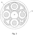
- the epicyclic gearbox 30 is shown by way of example in greater detail in Fig. 3 .
- Each of the sun gear 28, planet gears 32 and ring gear 38 comprise teeth about their periphery to intermesh with the other gears. However, for clarity only exemplary portions of the teeth are illustrated in Fig. 3 .
- Practical applications of a planetary epicyclic gearbox 30 generally comprise at least three planet gears 32.
- the epicyclic gearbox 30 illustrated by way of example in Fig. 2 and Fig. 3 is of the planetary type, in that the planet carrier 34 is coupled to an output shaft via linkages 36, with the ring gear 38 fixed.
- the epicyclic gearbox 30 may be a star arrangement, in which the planet carrier 34 is held fixed, with the ring (or annulus) gear 38 allowed to rotate. In such an arrangement the fan 23 is driven by the ring gear 38.
- the gearbox 30 may be a differential gearbox in which the ring gear 38 and the planet carrier 34 are both allowed to rotate.
- Fig. 2 and Fig. 3 are by way of example only, and various alternatives are within the scope of the present disclosure.
- any suitable arrangement may be used for locating the gearbox 30 in the engine 10 and/or for connecting the gearbox 30 to the engine 10.
- the connections (such as the linkages 36, 40 in the Fig. 2 example) between the gearbox 30 and other parts of the engine 10 (such as the input shaft 26, the output shaft and the fixed structure 24) may have any desired degree of stiffness or flexibility.
- any suitable arrangement of the bearings between rotating and stationary parts of the engine may be used, and the disclosure is not limited to the exemplary arrangement of Fig. 2 .
- the gearbox 30 has a star arrangement (described above)
- the skilled person would readily understand that the arrangement of output and support linkages and bearing locations would typically be different to that shown by way of example in Fig. 2 .
- the present disclosure extends to a gas turbine engine having any arrangement of gearbox styles (for example star or planetary), support structures, input and output shaft arrangement, and bearing locations.
- gearbox styles for example star or planetary
- support structures for example star or planetary
- input and output shaft arrangement for example star or planetary
- bearing locations for example star or planetary
- the gearbox may drive additional and/or alternative components (e.g. the intermediate pressure compressor and/or a booster compressor).
- additional and/or alternative components e.g. the intermediate pressure compressor and/or a booster compressor.
- gas turbine engines to which the present disclosure may be applied may have alternative configurations.
- such engines may have an alternative number of compressors and/or turbines and/or an alternative number of interconnecting shafts.
- the gas turbine engine shown in Fig. 1 has a split flow nozzle 20, 22 meaning that the flow through the bypass duct 22 has its own nozzle that is separate to and radially outside the core engine nozzle 20.
- this is not limiting, and any aspect of the present disclosure may also apply to engines in which the flow through the bypass duct 22 and the flow through the core 11 are mixed, or combined, before (or upstream of) a single nozzle, which may be referred to as a mixed flow nozzle.
- One or both nozzles may have a fixed or variable area.
- the described example relates to a turbofan engine, the disclosure may apply, for example, to any type of gas turbine engine, such as an open rotor (in which the fan stage is not surrounded by a nacelle) or turboprop engine, for example.
- the geometry of the gas turbine engine 10, and components thereof, is defined by a conventional axis system, comprising an axial direction (which is aligned with the rotational axis 9), a radial direction (in the bottom-to-top direction in Fig. 1 ), and a circumferential direction (perpendicular to the page in the Fig. 1 view).
- the axial, radial and circumferential directions are mutually perpendicular.
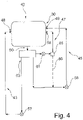
- Fig. 4 shows a first embodiment of an oil system 42 of the gas turbine engine 10.
- the oil system 42 comprises a first oil circuit 43, a second oil circuit 45 and at least a third oil circuit 47.
- the first oil circuit 43, the second oil circuit 45 and the third oil circuit 45 are fluidly coupled with a common outlet 50 of the gearbox 30. Further, the first oil circuit 43, the second oil circuit 45 and the third oil circuit 45 each are fluidly coupled with a separate inlet 48, 49, 56 of the gearbox 30.
- the first oil circuit 43 and the second oil circuit 45 each include a pump 57, 58 driven by the core shaft 26 or the core shaft 27.
- the third oil circuit 47 includes a pump 61 driven by the fan 23 or the core shaft 27 or any other suitable drive unit, for example an electric drive unit or the like.
- the outlet 50 of the gearbox includes a device 63 configured to direct oil from the gearbox 30 to the first oil circuit 43, to the second oil circuit 45 and depending on the respective embodiment of the gas turbine engine 10 to the third oil circuit 47 when the feeding to the gearbox 30 is exceeding a predefined oil flow rate, or is deviating an operational value corresponding with that oil flow rate. Additionally, the device 63 is configured to direct the oil from the gearbox 30 solely to the third oil circuit 47 when the feeding to the gearbox is less than or equal to the predefined flow rate or is less than or equal to at least one corresponding operational value or is greater than or equal to at least one further corresponding operational value.
- the third oil circuit 47 comprises in a further embodiment a valve unit 85 between the outlet 50 and the inlet 56 of the gearbox 30.
- the valve unit 85 is configured to direct oil from the outlet 50 to the second oil circuit 45 through an optional duct 86 when the feeding to the gearbox 30 is exceeding the predefined oil flow rate or is deviating the at least one operational value.
- Fig. 5 shows a second embodiment of an oil system 42 of the gas turbine engine 10.
- the oil system 42 comprises a first oil circuit 43 including a heat exchanger 44, a second oil circuit 45 including a heat exchanger 46 and at least a third oil circuit 47.
- the first oil circuit 43 and the second oil circuit 45 are fluidly coupled with an inlet 48, 49 of the gearbox 30 as well as with an outlet 50 of the gearbox 30.
- the second oil circuit 45 is configured to direct oil from an oil tank 53 to a turbomachinery 68 of the gas turbine engine 10.
- the inlet 48 is fluidly coupled with an oil transfer unit 66 which is arranged inside the gearbox 30.
- the inlet 49 is fluidly coupled to a further oil transfer unit 62 of the gearbox 30 which is located inside the gearbox 30.
- the first oil circuit 43 and the second oil circuit 45 are fluidly coupled with an inlet 51, 52 of the oil tank 53 as well as with an outlet 54, 55 of the oil tank 53.
- the third oil circuit 47 is fluidly coupled with an inlet 56 of the gearbox 30 as well as with the outlet 50 of the gearbox 30.
- first oil circuit 43 and the second oil circuit 45 each include a scavenge pump 57, 58 and a feeding pump 59, 60 driven by the core shaft 26 and accordingly by an auxiliary gearbox 31 of the gas turbine engine 10.
- the third oil circuit 47 includes a feeding pump 61 driven by the fan 23.
- the third oil circuit 47 may comprise an additional oil tank and a scavenge pump between the oil reservoir 64 and the feeding pump 61.
- the first oil circuit 43 and the second oil circuit 45 are configured to receive oil from the oil tank 53 and to direct the received oil to the gearbox 30.
- the third oil circuit 47 is configured to receive oil from the outlet 50 of the gearbox 30 and to direct the received oil to the inlet 49 and the oil transfer unit 62 of the gearbox 30.
- the heat exchanger 44 of the first oil circuit 43 is arranged between the feeding pump 59 and the inlet 48 of the gearbox 30.
- the heat exchanger 46 of the second oil circuit 45 is arranged between the feeding pump 60 and an optional throttle 67 which is positioned between the inlet 49 of the gearbox 30 and the feeding pump 60 of the second oil circuit 45.
- the outlet 50 of the gearbox includes a device 63 configured to direct oil from the gearbox 30 to the first oil circuit 43, to the second oil circuit 45 and to the third oil circuit 47 when the feeding to the gearbox 30 is exceeding a predefined oil flow rate, or is deviating an operational value corresponding with that oil flow rate. Additionally, the device 63 is configured to direct the oil from the gearbox 30 to the third oil circuit 47 when the feeding to the gearbox is less than or equal to the predefined flow rate or is less than or equal to at least one corresponding operational value or is greater than or equal to at least one further corresponding operational value.
- the device 63 includes an oil reservoir 64 from which oil received from the gearbox 30 can be directly conducted back into the gearbox 30 via the third oil circuit 47, and into the oil tank 53 via the first oil circuit 43 and the second oil circuit 45.
- Oil is conducted from the oil reservoir 64 only via the third oil circuit 47 directly to the inlet 56 of the gearbox 30 as long as a filling level of the oil reservoir 64 is less than the defined filling level 65 of the oil reservoir 64.
- oil is directed via the first oil circuit 43 and via the second oil circuit 45 to the oil tank 53 and via the third oil circuit 47 to the inlet 56 as soon as the defined filling level 65 of the oil reservoir 64 is reached.
- the oil tank 53 incorporates offset outlets 25, 29 to each of the oil circuits 43, 45.
- the turbomachinery circuit 45 offset outlet 29 is positioned higher in the oil tank 53 than the offset outlet 25 of the first circuit 43 feeding solely to the gearbox 30.
- the turbomachinery circuit 45 will generate a low oil pressure warning or another warning signal first without the first circuit 43 having yet been affected.
- the level of offset can be designed such that, under all reasonable rates of oil loss, the pilot has reacted to the warning before the first oil circuit 43 feed to the journal bearings is lost or reduced.
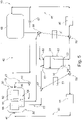
- FIG. 6 A third embodiment of the oil system 42 of the gas turbine engine 30 is shown in Fig. 6 .
- the structure and the function of the oil system 42 according to Fig. 6 corresponds substantially to the structure and the function of the oil system 42 according to Fig. 5 .
- the device 63 of the oil system 42 according to Fig. 6 differs from the device 63 of the oil system 42 pursuant to Fig. 5 .
- the device 63 includes a first valve unit 69 and a second valve unit 70.
- the first valve 69 unit is configured to block the connection between an outlet 90 of the gearbox and the inlet 51 of the oil tank 53 via the first oil circuit 43, and is configured to unblock the connection between an outlet 91 and the inlet 56 of the gearbox 30 via the third oil circuit 47 as long as the feeding to the gearbox 30 from the first oil circuit 43 is less than the predefined oil flow rate or the corresponding operational pressure value.
- the first valve unit 69 comprises a solenoid valve 71 and a 5/2 directional control valve 72.
- the solenoid valve 71 is configured to apply a feeding pressure in the first oil circuit 43 upstream of the inlet 48 of the gearbox 30 to a control surface 73 of a valve control spool 74 of the 5/2 directional control valve 72 in a first operational state of the solenoid valve 71.
- the solenoid valve 71 can be switched against a spring load from a second operational state into the first operational state by an appropriate electrical control signal. In the second operational state of the solenoid valve 71 the feeding pressure in the first oil circuit 43 is not applied to the spool 74 of the 5/2 directional control valve 72.
- a control line 75 between the solenoid valve 71 and the 5/2 directional control valve 72 is fluidly coupled upstream of the 5/2 directional control valve 72 with the scavenge pump 57 by a throttle 76.
- a spring load of a spring 92 is applied to the spool 74 of the 5/2 directional control valve 72 in the direction of a first position of the spool 74 in which the outlet 91 of the gearbox 30 is fluidly coupled with the inlet 56 of the gearbox 30 via the third oil circuit 47 and the connection between the outlet 90 and the inlet 51 of the tank 53 via the first oil circuit 43 is blocked by the 5/2 directional control valve 72.
- the feeding pressure in the first oil circuit 43 could be applied opposed to the spring load to the spool 74 and in the direction of a second position of the spool 74 in such a manner that the spool 74 is moved to the second position by the feeding pressure if the compressive force resulting by the feeding pressure exceeds the spring load.
- the outlet 90 of the gearbox 30 is fluidly coupled with the inlet 51 of the tank 53 via the first oil circuit 43.
- the outlet 91 of the gearbox 30 is fluidly coupled via the third oil circuit 47 and the 5/2 directional control valve 72 with the inlet 51 of the tank 53 in the second position of the spool 74.
- the second valve unit 70 is configured to block the connection between an outlet 94 of the gearbox 30 and the oil tank 53 via the second oil circuit 45 as long as the feeding to the gearbox 30 from the second oil circuit 45 is less than the predefined oil flow rate or is less than or equal to at least one corresponding operational value or is greater than or equal to at least one further corresponding operational value.
- the second valve unit 70 comprises a solenoid valve 77 and a 2/2 directional control valve 78.
- the solenoid valve 77 is configured to apply a feeding pressure in the second oil circuit 45 upstream of the inlet 49 of the gearbox 30 to a control surface 79 of a valve control spool 80 of the 2/2 directional control valve 78 in a first operational state of the solenoid valve 77.
- the solenoid valve 77 can be switched against a spring load from a second operational state into the first operational state by an appropriate electrical control signal.
- the feeding pressure in the second oil circuit 45 is not applied to the spool 80 of the 2/2 directional control valve 78.
- a control line 81 between the solenoid valve 77 and the 2/2 directional control valve 78 is fluidly coupled upstream of the 2/2 directional control valve 78 with the scavenge pump 58 by an optional throttle 82.
- a spring load of a spring 93 is applied to the spool 80 of the 2/2 directional control valve 78 in the direction of a first position of the spool 80 in which the connection between the outlet 94 and the inlet 52 of the tank 53 via the second oil circuit 45 is blocked by the 2/2 directional control valve 78.
- the feeding pressure in the second oil circuit 45 could be applied opposed to the spring load to the spool 80 and in the direction of a second position of the spool 80 in such a manner that the spool 80 is moved to the second position by the feeding pressure if the compressive force resulting by the feeding pressure exceeds the spring load.
- the outlet 94 of the gearbox 30 is fluidly coupled with the inlet 52 of the gearbox 30 via the second oil circuit 45.
- first oil circuit 43 and the second oil circuit 45 are including separate oil tanks instead of the common oil tank 53.
- the two pumps 57, 59 and 58, 60 of each oil circuit 43, 45 are connected with a shear neck drive to couple and de-couple the two units.
Landscapes
- Engineering & Computer Science (AREA)
- General Engineering & Computer Science (AREA)
- Mechanical Engineering (AREA)
- Chemical & Material Sciences (AREA)
- Combustion & Propulsion (AREA)
- Quality & Reliability (AREA)
- Structures Of Non-Positive Displacement Pumps (AREA)
Claims (14)
- Gasturbinentriebwerk (10) für ein Luftfahrzeug, das Folgendes umfasst:einen Triebwerkskern (11), umfassend zumindest eine Turbine (17, 19), zumindest einen Kompressor (14, 15) und zumindest eine Welle (26, 27), die die Turbine (17, 19) mit dem Kompressor (14, 15) verbindet;ein Gebläse (23), das sich stromaufwärts des Triebwerkskerns (11) befindet, wobei das Gebläse (23) eine Mehrzahl von Gebläseschaufeln umfasst;ein Getriebe (30), das einen Eingang von der Welle (26) empfängt und einen Antrieb zu dem Gebläse (23) abgibt, um das Gebläse (23) bei einer niedrigeren Drehzahl als die Welle (26) anzutreiben;einen ersten Ölkreislauf (43), einen zweiten Ölkreislauf (45) und zumindest einen dritten Ölkreislauf (47);wobei der erste Ölkreislauf (43), der zweite Ölkreislauf (45) und der dritte Ölkreislauf (47) mit zumindest einem Einlass (48, 49, 56) des Getriebes (30) sowie mit zumindest einem Auslass (50, 90, 91, 94) des Getriebes (30) fluidisch gekoppelt sind;wobei der erste Ölkreislauf (43) und der zweite Ölkreislauf (45) jeweils zumindest eine Pumpe (57, 58, 59, 60) beinhalten;wobei der dritte Ölkreislauf (47) eine Pumpe (61) beinhaltet; undwobei der mindestens eine Auslass (50, 90, 91, 94) des Getriebes (30) eine Vorrichtung (63) beinhaltet, die im Gebrauch dazu ausgelegt ist, Öl von dem Getriebe (30) zu dem ersten Ölkreislauf (43) und/oder zu dem zweiten Ölkreislauf (45) und/oder zu dem dritten Ölkreislauf (47) zu leiten, wenn die Zufuhr zu dem Getriebe (30) eine vordefinierte Öldurchflussrate übersteigt oder in zumindest einem Betriebswert, der der Ölflussrate entspricht, abweicht, und ferner im Gebrauch dazu ausgelegt ist, das Öl von dem Getriebe (30) zu dem dritten Ölkreislauf (47) zu leiten, wenn die Zufuhr zu dem Getriebe (30) kleiner als oder gleich der vordefinierten Öldurchflussrate ist oderkleiner als oder gleich zumindest einem entsprechenden Betriebswert ist oder größer als oder gleich zumindest einem weiteren entsprechenden Betriebswert ist;wobei:der zweite Ölkreislauf (45) dazu ausgelegt ist, Öl von einem Öltank (53) zu einer Turbomaschine (68) des Gasturbinentriebwerks (10) zu leiten;die Pumpen (57, 58, 59, 60) des ersten Ölkreislaufs (43) und des zweiten Ölkreislaufs (45) durch die Welle (26) angetrieben werden; unddie Pumpe (61) des dritten Ölkreislaufs (47) durch das Gebläse (23) angetrieben wird.
- Gasturbinentriebwerk nach Anspruch 1, wobei:die Turbine eine erste Turbine (19) ist, der Kompressor ein erster Kompressor (14) ist und die Welle eine erste Kernwelle (26) ist;der Triebwerkskern (11) ferner einer zweite Turbine (17), einen zweiten Kompressor (15) und eine zweite Kernwelle (27), die die zweite Turbine (17) mit dem zweiten Kompressor (15) verbindet, umfasst; unddie zweite Turbine (17), der zweite Kompressor (15) und die zweite Kernwelle (27) so angeordnet sind, dass sie sich mit einer höheren Drehzahl drehen als die erste Kernwelle (26).
- Gasturbinentriebwerk nach Anspruch 1 oder 2, wobei:
der erste Ölkreislauf (43) einen Wärmetauscher (44) beinhaltet. - Gasturbinentriebwerk nach einem der Ansprüche 1 bis 3, wobei:
der zweite Ölkreislauf (45) einen Wärmetauscher (46) beinhaltet. - Gasturbinentriebwerk nach einem der Ansprüche 1 bis 4, wobei:
der erste Ölkreislauf (43) und der zweite Ölkreislauf (45) jeweils eine Rücklaufpumpe (57, 58) und eine Förderpumpe (59, 60) beinhalten, die durch die Kernwelle (26) angetrieben werden. - Gasturbinentriebwerk nach einem der Ansprüche 1 bis 5, wobei:
die Vorrichtung (63) einen Ölspeicher (64) beinhaltet, aus dem im Gebrauch aus dem Getriebe (30) aufgenommenes Öl direkt zurück in das Getriebe (30) über den dritten Ölkreislauf (47) geleitet werden kann, und in das Getriebe (30) über den ersten Ölkreislauf (43) und den zweiten Ölkreislauf (45) zurückgeleitet werden kann, wobei Öl von dem Ölspeicher (64) nur über den dritten Ölkreislauf (47) direkt zu dem Einlass (56) des Getriebes (30) geleitet wird, solange ein Füllstand des Ölspeichers (64) kleiner als ein definierter Füllstand (65) des Ölspeichers (64) ist, und Öl über den ersten Ölkreislauf (43) und über den zweiten Ölkreislauf (45) zu dem Öltank (53) geleitet werden kann, sobald der definierte Füllstand (65) des Ölspeichers (64) erreicht ist. - Gasturbinentriebwerk nach einem der Ansprüche 1 bis 5, wobei:
die Vorrichtung (63) eine erste Ventileinheit (69) und eine zweite Ventileinheit (70) beinhaltet, wobei die erste Ventileinheit (69) dazu ausgelegt ist, die Verbindung zwischen dem zumindest einen Auslass (50, 90, 91, 94) des Getriebes (30) und dem Einlass (51) des Öltanks (53) über den ersten Ölkreislauf (43) zu sperren, und dazu ausgelegt ist, die Verbindung zwischen dem zumindest einen Auslass (50, 90, 91, 94) des Getriebes (30) und dem Einlass (56) des Getriebes (30) über den dritten Ölkreislauf (47) zu entsperren, solange im Gebrauch die Zufuhr zu dem Getriebe (30) von dem ersten Ölkreislauf (43) kleiner als oder gleich der vordefinierten Öldurchflussrate ist oder kleiner als oder gleich zumindest einem entsprechenden Betriebswert ist oder größer als oder gleich zumindest einem weiteren entsprechenden Betriebswert ist. - Gasturbinentriebwerk nach Anspruch 7, wobei:
die zweite Ventileinheit (70) dazu ausgelegt ist, die Verbindung zwischen dem zumindest einen Auslass (50, 90, 91, 94) des Getriebes (30) und dem Einlass (49) des Getriebes (30) über den zweiten Ölkreislauf (45) zu sperren, solange im Gebrauch die Zufuhr zu dem Getriebe (30) von dem zweiten Ölkreislauf (45) kleiner als oder gleich der vordefinierten Öldurchflussrate ist oder kleiner als oder gleich zumindest einem entsprechenden Betriebswert ist oder größer als oder gleich zumindest einem weiteren entsprechenden Betriebswert ist. - Gasturbinentriebwerk nach Anspruch 7 oder 8, wobei:die erste Ventileinheit (69) ein Magnetventil (71) und ein 5/2-Wegeventil (72) umfasst,wobei das Magnetventil (71) dazu ausgelegt ist, im Gebrauch einen Zufuhrdruck in dem ersten Ölkreislauf (43) stromaufwärts des Einlasses (48) des Getriebes (30) auf eine Steuerfläche (73) eines Ventilsteuerschiebers (74) des 5/2-Wegeventils (72) in einem ersten Betriebszustand des Magnetventils (71) aufzubringen.
- Gasturbinentriebwerk nach Anspruch 9, wobei:
eine Steuerleitung (75) zwischen dem Magnetventil (71) und dem 5/2-Wegeventil (72) stromaufwärts des 5/2-Wegeventils (72) mit der Rücklaufpumpe (57) durch eine Drossel (76) fluidisch gekoppelt ist. - Gasturbinentriebwerk nach einem der Ansprüche 7 bis 10, wobei:die zweite Ventileinheit (70) ein Magnetventil (77) und ein 2/2-Wegeventil (78) umfasst,wobei das Magnetventil (77) dazu ausgelegt ist, im Gebrauch einen Zufuhrdruck in dem zweiten Ölkreislauf (45) stromaufwärts des Einlasses (49) des Getriebes (30) auf eine Steuerfläche (79) eines Ventilsteuerschiebers (80) des 2/2-Wegeventils (78) in einem ersten Betriebszustand des Magnetventils (77) aufzubringen.
- Gasturbinentriebwerk nach Anspruch 11, wobei:
eine Steuerleitung (81) zwischen dem Magnetventil (77) und dem 2/2-Wegeventil (78) stromaufwärts des 2/2-Wegeventils (78) mit der Rücklaufpumpe (58) durch eine Drossel (82) fluidisch gekoppelt ist. - Gasturbinentriebwerk nach einem der Ansprüche 1 bis 12, wobei:
der erste Ölkreislauf (43) und der zweite Ölkreislauf (45) mit einem Einlass (51, 52) eines Öltanks (53) sowie mit einem Auslass (54, 55) des Öltanks (53) fluidisch gekoppelt sind, und der erste Ölkreislauf (43) und der zweite Ölkreislauf (45) dazu ausgelegt sind, Öl aus dem Öltank (53) aufzunehmen und das aufgenommene Öl zu dem Getriebe (30) zu leiten. - Gasturbinentriebwerk nach einem der Ansprüche 1 bis 13, wobei:
eine Drossel (67) zwischen dem Einlass (49) des Getriebes (30) und der Förderpumpe (60) des zweiten Ölkreislaufs (45) positioniert ist.
Applications Claiming Priority (1)
| Application Number | Priority Date | Filing Date | Title |
|---|---|---|---|
| DE102018109100 | 2018-04-17 |
Publications (2)
| Publication Number | Publication Date |
|---|---|
| EP3557028A1 EP3557028A1 (de) | 2019-10-23 |
| EP3557028B1 true EP3557028B1 (de) | 2022-06-01 |
Family
ID=66091863
Family Applications (1)
| Application Number | Title | Priority Date | Filing Date |
|---|---|---|---|
| EP19166136.2A Active EP3557028B1 (de) | 2018-04-17 | 2019-03-29 | Gasturbinentriebwerk |
Country Status (4)
| Country | Link |
|---|---|
| US (1) | US11131214B2 (de) |
| EP (1) | EP3557028B1 (de) |
| CN (1) | CN110388283A (de) |
| CA (1) | CA3040146A1 (de) |
Families Citing this family (33)
| Publication number | Priority date | Publication date | Assignee | Title |
|---|---|---|---|---|
| GB201804506D0 (en) * | 2018-03-21 | 2018-05-02 | Rolls Royce Plc | Oil system |
| US11519820B2 (en) * | 2018-09-19 | 2022-12-06 | Rolls-Royce Deutschland Ltd & Co Kg | Method and device for monitoring a journal bearing |
| GB201917773D0 (en) | 2019-12-05 | 2020-01-22 | Rolls Royce Plc | High power epicyclic gearbox and operation thereof |
| JP7307657B2 (ja) * | 2019-10-21 | 2023-07-12 | 川崎重工業株式会社 | ガスタービンエンジン |
| US12297779B2 (en) * | 2019-12-05 | 2025-05-13 | Rolls-Royce Plc | Geared gas turbine engine |
| GB201917766D0 (en) * | 2019-12-05 | 2020-01-22 | Rolls Royce Plc | Geared gas turbine engine |
| GB201917761D0 (en) * | 2019-12-05 | 2020-01-22 | Rolls Royce Plc | Reliable gearbox for gas turbine engine |
| GB201917782D0 (en) | 2019-12-05 | 2020-01-22 | Rolls Royce Plc | High power epicyclic gearbox and operation thereof |
| GB201917779D0 (en) * | 2019-12-05 | 2020-01-22 | Rolls Royce Plc | Aircraft engine |
| GB201917769D0 (en) * | 2019-12-05 | 2020-01-22 | Rolls Royce Plc | Geared gas turbine engine |
| GB201917765D0 (en) | 2019-12-05 | 2020-01-22 | Rolls Royce Plc | Aircraft engine |
| GB201917762D0 (en) * | 2019-12-05 | 2020-01-22 | Rolls Royce Plc | Reliable gearbox for gas turbine engine |
| GB201917772D0 (en) * | 2019-12-05 | 2020-01-22 | Rolls Royce Plc | Aircraft engine |
| GB201917764D0 (en) * | 2019-12-05 | 2020-01-22 | Rolls Royce Plc | Reliable gearbox for gas turbine engine |
| GB201917777D0 (en) | 2019-12-05 | 2020-01-22 | Rolls Royce Plc | High power epicyclic gearbox and operation thereof |
| GB201917763D0 (en) * | 2019-12-05 | 2020-01-22 | Rolls Royce Plc | Gas turbine engine arrangement |
| GB201917774D0 (en) * | 2019-12-05 | 2020-01-22 | Rolls Royce Plc | Gas turbine engine arrangement |
| GB201917767D0 (en) * | 2019-12-05 | 2020-01-22 | Rolls Royce Plc | High power epicyclic gearbox and operation thereof |
| GB201917760D0 (en) | 2019-12-05 | 2020-01-22 | Rolls Royce Plc | Aircraft engine |
| GB201917781D0 (en) * | 2019-12-05 | 2020-01-22 | Rolls Royce Plc | Reliable gearbox for gas turbine engine |
| GB201917776D0 (en) * | 2019-12-05 | 2020-01-22 | Rolls Royce Plc | Aircraft engine |
| GB201917770D0 (en) * | 2019-12-05 | 2020-01-22 | Rolls Royce Plc | Reliable gearbox for gas turine engine |
| DE102020102292A1 (de) | 2020-01-30 | 2021-08-05 | Rolls-Royce Deutschland Ltd & Co Kg | Ölsystem eines Gasturbinentriebwerkes mit einem ersten Ölkreislauf und mit wenigstens einem zweiten Ölkreislauf sowie Gasturbinentriebwerk |
| DE102020104933A1 (de) | 2020-02-25 | 2021-08-26 | Rolls-Royce Deutschland Ltd & Co Kg | Ölsystem eines Gasturbinentriebwerkes mit einem ersten Ölkreislauf und mit wenigstens einem zweiten Ölkreislauf sowie Gasturbinentriebwerk |
| DE102020132918A1 (de) | 2020-12-10 | 2022-06-15 | Rolls-Royce Deutschland Ltd & Co Kg | Ölsystem eines Gasturbinentriebwerkes |
| US20250137529A1 (en) * | 2022-06-22 | 2025-05-01 | General Electric Company | Gearbox assembly with lubricant extraction volume ratio |
| US12320418B2 (en) | 2022-06-22 | 2025-06-03 | General Electric Company | Gearbox assembly with lubricant extraction volume ratio |
| GB202214153D0 (en) | 2022-09-28 | 2022-11-09 | Rolls Royce Plc | Modulated heat management for geared gas turbine engines |
| US12158104B2 (en) | 2022-09-30 | 2024-12-03 | General Electric Company | Conformal structure for a gas turbine engine |
| IT202300000213A1 (it) * | 2023-01-11 | 2024-07-11 | Ge Avio Srl | Architettura di un impianto di alimentazione di olio |
| US12276333B2 (en) * | 2023-06-21 | 2025-04-15 | General Electric Company | Gearbox assembly lubrication system for a turbine engine |
| FR3156829B1 (fr) * | 2023-12-14 | 2025-11-28 | Safran Aircraft Engines | Module pour une turbomachine comprenant un circuit d’alimentation en huile |
| GB202319156D0 (en) * | 2023-12-14 | 2024-01-31 | Rolls Royce Plc | Fuel supply system |
Family Cites Families (21)
| Publication number | Priority date | Publication date | Assignee | Title |
|---|---|---|---|---|
| US8307626B2 (en) | 2009-02-26 | 2012-11-13 | United Technologies Corporation | Auxiliary pump system for fan drive gear system |
| US8230974B2 (en) | 2009-05-22 | 2012-07-31 | United Technologies Corporation | Windmill and zero gravity lubrication system for a gas turbine engine |
| US8484942B1 (en) * | 2012-05-30 | 2013-07-16 | United Technologies Corporation | Planetary gear system arrangement with auxiliary oil system |
| US20130319006A1 (en) * | 2012-05-31 | 2013-12-05 | Francis Parnin | Direct feed auxiliary oil system for geared turbofan engine |
| US9410448B2 (en) | 2012-05-31 | 2016-08-09 | United Technologies Corporation | Auxiliary oil system for negative gravity event |
| US20140124297A1 (en) * | 2012-11-06 | 2014-05-08 | United Technologies Corporation | Pressurized reserve lubrication system for a gas turbine engine |
| US9995177B2 (en) | 2013-02-28 | 2018-06-12 | United Technologies Corporation | Self cleaning debris filter for fan drive gear system |
| EP2964927B1 (de) * | 2013-03-04 | 2019-04-10 | United Technologies Corporation | Gasturbinenmotorschmiersystem |
| EP2971662B1 (de) | 2013-03-15 | 2020-10-28 | United Technologies Corporation | Schmiermittelzirkulierung durch eine turbinenmotorkomponente mit parallelen pumpen |
| WO2015047514A2 (en) * | 2013-07-07 | 2015-04-02 | United Technologies Corporation | Inseparable machined lubricant manifold |
| EP3699413B1 (de) * | 2013-07-07 | 2022-12-21 | Raytheon Technologies Corporation | Radialröhrenfilter für getriebesystemverteiler eines lüfterantriebs |
| US10107142B2 (en) | 2013-09-13 | 2018-10-23 | United Technologies Corporation | Fan drive gear system auxiliary pump monitoring system |
| US10458330B2 (en) * | 2014-01-20 | 2019-10-29 | United Technologies Corporation | Auxiliary oil system for geared gas turbine engine |
| BE1022364B1 (fr) * | 2014-10-27 | 2016-03-17 | Techspace Aero S.A. | Compresseur de turbomachine axiale avec double rotors contrarotatifs |
| US9909453B2 (en) | 2015-05-19 | 2018-03-06 | General Electric Company | Lubrication system for a turbine engine |
| US20160363055A1 (en) * | 2015-06-09 | 2016-12-15 | Rolls-Royce North American Technologies, Inc. | Off-set geared turbofan engine |
| US10041489B2 (en) * | 2015-10-22 | 2018-08-07 | United Technologies Corporation | Auxiliary pump and gas turbine engine oil circuit monitoring system |
| US10107135B2 (en) | 2015-10-26 | 2018-10-23 | United Technologies Corporation | Gas turbine engine with gearbox health features |
| US10634053B2 (en) * | 2015-12-21 | 2020-04-28 | United Technologies Corporation | Electric windmill pump for gearbox durability |
| US10513949B2 (en) | 2016-09-09 | 2019-12-24 | United Technologies Corporation | Auxiliary journal oil supply system |
| US12259036B2 (en) | 2018-04-20 | 2025-03-25 | Rtx Corporation | Electric motor driven auxiliary oil system for geared gas turbine engine |
-
2019
- 2019-03-29 EP EP19166136.2A patent/EP3557028B1/de active Active
- 2019-04-11 CA CA3040146A patent/CA3040146A1/en active Pending
- 2019-04-12 US US16/382,923 patent/US11131214B2/en active Active
- 2019-04-17 CN CN201910308267.XA patent/CN110388283A/zh active Pending
Also Published As
| Publication number | Publication date |
|---|---|
| CA3040146A1 (en) | 2019-10-17 |
| US20190316488A1 (en) | 2019-10-17 |
| CN110388283A (zh) | 2019-10-29 |
| US11131214B2 (en) | 2021-09-28 |
| EP3557028A1 (de) | 2019-10-23 |
Similar Documents
| Publication | Publication Date | Title |
|---|---|---|
| EP3557028B1 (de) | Gasturbinentriebwerk | |
| EP3557010B1 (de) | Gasturbinentriebwerk | |
| US11313454B2 (en) | Lubrication system | |
| US10823174B2 (en) | Planetary gear device with an oil supply appliance, gas turbine engine with a planetary gear device and method for manufacturing a vane pump | |
| EP3792471B2 (de) | Gasturbinentriebwerk | |
| US11352905B2 (en) | Lubrication system | |
| EP3808963B1 (de) | Gasturbinentriebwerk | |
| EP3667022B1 (de) | Eiskristallschutz für ein turbostrahltriebwerk | |
| EP3611398B1 (de) | Stabilisierungslagersystem für getriebefanmotoren | |
| EP3835563B1 (de) | Klimaanlage im flugzeug | |
| EP3569840B1 (de) | Gasturbinentriebwerk | |
| EP3719276A1 (de) | Ölrohranordnung | |
| EP3564496A1 (de) | Öltankbefüllungssystem | |
| US11619168B2 (en) | Gas turbine engine lubrication system | |
| US11506082B2 (en) | Oil scavenge system | |
| US20230203992A1 (en) | Gas turbine engine of an aircraft comprising a transmission | |
| EP3663542B1 (de) | Ölversorgungsanordnung für lager | |
| EP3741963B1 (de) | Gasturbinentriebwerk | |
| US20200182151A1 (en) | Oil supply arrangement for bearing | |
| EP3708808A1 (de) | Kühlung eines kraftstoffverteilers | |
| WO2020078724A1 (en) | Oil system of a gas turbine engine and gas turbine engine |
Legal Events
| Date | Code | Title | Description |
|---|---|---|---|
| PUAI | Public reference made under article 153(3) epc to a published international application that has entered the european phase |
Free format text: ORIGINAL CODE: 0009012 |
|
| STAA | Information on the status of an ep patent application or granted ep patent |
Free format text: STATUS: THE APPLICATION HAS BEEN PUBLISHED |
|
| AK | Designated contracting states |
Kind code of ref document: A1 Designated state(s): AL AT BE BG CH CY CZ DE DK EE ES FI FR GB GR HR HU IE IS IT LI LT LU LV MC MK MT NL NO PL PT RO RS SE SI SK SM TR |
|
| AX | Request for extension of the european patent |
Extension state: BA ME |
|
| RAP1 | Party data changed (applicant data changed or rights of an application transferred) |
Owner name: ROLLS-ROYCE PLC Owner name: ROLLS-ROYCE DEUTSCHLAND LTD & CO KG |
|
| STAA | Information on the status of an ep patent application or granted ep patent |
Free format text: STATUS: REQUEST FOR EXAMINATION WAS MADE |
|
| 17P | Request for examination filed |
Effective date: 20200424 |
|
| RBV | Designated contracting states (corrected) |
Designated state(s): AL AT BE BG CH CY CZ DE DK EE ES FI FR GB GR HR HU IE IS IT LI LT LU LV MC MK MT NL NO PL PT RO RS SE SI SK SM TR |
|
| GRAP | Despatch of communication of intention to grant a patent |
Free format text: ORIGINAL CODE: EPIDOSNIGR1 |
|
| STAA | Information on the status of an ep patent application or granted ep patent |
Free format text: STATUS: GRANT OF PATENT IS INTENDED |
|
| INTG | Intention to grant announced |
Effective date: 20220111 |
|
| GRAS | Grant fee paid |
Free format text: ORIGINAL CODE: EPIDOSNIGR3 |
|
| GRAA | (expected) grant |
Free format text: ORIGINAL CODE: 0009210 |
|
| STAA | Information on the status of an ep patent application or granted ep patent |
Free format text: STATUS: THE PATENT HAS BEEN GRANTED |
|
| AK | Designated contracting states |
Kind code of ref document: B1 Designated state(s): AL AT BE BG CH CY CZ DE DK EE ES FI FR GB GR HR HU IE IS IT LI LT LU LV MC MK MT NL NO PL PT RO RS SE SI SK SM TR |
|
| REG | Reference to a national code |
Ref country code: GB Ref legal event code: FG4D |
|
| REG | Reference to a national code |
Ref country code: AT Ref legal event code: REF Ref document number: 1495504 Country of ref document: AT Kind code of ref document: T Effective date: 20220615 Ref country code: CH Ref legal event code: EP |
|
| REG | Reference to a national code |
Ref country code: IE Ref legal event code: FG4D |
|
| REG | Reference to a national code |
Ref country code: DE Ref legal event code: R096 Ref document number: 602019015312 Country of ref document: DE |
|
| REG | Reference to a national code |
Ref country code: LT Ref legal event code: MG9D |
|
| REG | Reference to a national code |
Ref country code: NL Ref legal event code: MP Effective date: 20220601 |
|
| PG25 | Lapsed in a contracting state [announced via postgrant information from national office to epo] |
Ref country code: SE Free format text: LAPSE BECAUSE OF FAILURE TO SUBMIT A TRANSLATION OF THE DESCRIPTION OR TO PAY THE FEE WITHIN THE PRESCRIBED TIME-LIMIT Effective date: 20220601 Ref country code: NO Free format text: LAPSE BECAUSE OF FAILURE TO SUBMIT A TRANSLATION OF THE DESCRIPTION OR TO PAY THE FEE WITHIN THE PRESCRIBED TIME-LIMIT Effective date: 20220901 Ref country code: LT Free format text: LAPSE BECAUSE OF FAILURE TO SUBMIT A TRANSLATION OF THE DESCRIPTION OR TO PAY THE FEE WITHIN THE PRESCRIBED TIME-LIMIT Effective date: 20220601 Ref country code: HR Free format text: LAPSE BECAUSE OF FAILURE TO SUBMIT A TRANSLATION OF THE DESCRIPTION OR TO PAY THE FEE WITHIN THE PRESCRIBED TIME-LIMIT Effective date: 20220601 Ref country code: GR Free format text: LAPSE BECAUSE OF FAILURE TO SUBMIT A TRANSLATION OF THE DESCRIPTION OR TO PAY THE FEE WITHIN THE PRESCRIBED TIME-LIMIT Effective date: 20220902 Ref country code: FI Free format text: LAPSE BECAUSE OF FAILURE TO SUBMIT A TRANSLATION OF THE DESCRIPTION OR TO PAY THE FEE WITHIN THE PRESCRIBED TIME-LIMIT Effective date: 20220601 Ref country code: ES Free format text: LAPSE BECAUSE OF FAILURE TO SUBMIT A TRANSLATION OF THE DESCRIPTION OR TO PAY THE FEE WITHIN THE PRESCRIBED TIME-LIMIT Effective date: 20220601 Ref country code: BG Free format text: LAPSE BECAUSE OF FAILURE TO SUBMIT A TRANSLATION OF THE DESCRIPTION OR TO PAY THE FEE WITHIN THE PRESCRIBED TIME-LIMIT Effective date: 20220901 |
|
| REG | Reference to a national code |
Ref country code: AT Ref legal event code: MK05 Ref document number: 1495504 Country of ref document: AT Kind code of ref document: T Effective date: 20220601 |
|
| PG25 | Lapsed in a contracting state [announced via postgrant information from national office to epo] |
Ref country code: RS Free format text: LAPSE BECAUSE OF FAILURE TO SUBMIT A TRANSLATION OF THE DESCRIPTION OR TO PAY THE FEE WITHIN THE PRESCRIBED TIME-LIMIT Effective date: 20220601 Ref country code: PL Free format text: LAPSE BECAUSE OF FAILURE TO SUBMIT A TRANSLATION OF THE DESCRIPTION OR TO PAY THE FEE WITHIN THE PRESCRIBED TIME-LIMIT Effective date: 20220601 Ref country code: LV Free format text: LAPSE BECAUSE OF FAILURE TO SUBMIT A TRANSLATION OF THE DESCRIPTION OR TO PAY THE FEE WITHIN THE PRESCRIBED TIME-LIMIT Effective date: 20220601 |
|
| PG25 | Lapsed in a contracting state [announced via postgrant information from national office to epo] |
Ref country code: NL Free format text: LAPSE BECAUSE OF FAILURE TO SUBMIT A TRANSLATION OF THE DESCRIPTION OR TO PAY THE FEE WITHIN THE PRESCRIBED TIME-LIMIT Effective date: 20220601 |
|
| PG25 | Lapsed in a contracting state [announced via postgrant information from national office to epo] |
Ref country code: SM Free format text: LAPSE BECAUSE OF FAILURE TO SUBMIT A TRANSLATION OF THE DESCRIPTION OR TO PAY THE FEE WITHIN THE PRESCRIBED TIME-LIMIT Effective date: 20220601 Ref country code: SK Free format text: LAPSE BECAUSE OF FAILURE TO SUBMIT A TRANSLATION OF THE DESCRIPTION OR TO PAY THE FEE WITHIN THE PRESCRIBED TIME-LIMIT Effective date: 20220601 Ref country code: RO Free format text: LAPSE BECAUSE OF FAILURE TO SUBMIT A TRANSLATION OF THE DESCRIPTION OR TO PAY THE FEE WITHIN THE PRESCRIBED TIME-LIMIT Effective date: 20220601 Ref country code: PT Free format text: LAPSE BECAUSE OF FAILURE TO SUBMIT A TRANSLATION OF THE DESCRIPTION OR TO PAY THE FEE WITHIN THE PRESCRIBED TIME-LIMIT Effective date: 20221003 Ref country code: EE Free format text: LAPSE BECAUSE OF FAILURE TO SUBMIT A TRANSLATION OF THE DESCRIPTION OR TO PAY THE FEE WITHIN THE PRESCRIBED TIME-LIMIT Effective date: 20220601 Ref country code: CZ Free format text: LAPSE BECAUSE OF FAILURE TO SUBMIT A TRANSLATION OF THE DESCRIPTION OR TO PAY THE FEE WITHIN THE PRESCRIBED TIME-LIMIT Effective date: 20220601 Ref country code: AT Free format text: LAPSE BECAUSE OF FAILURE TO SUBMIT A TRANSLATION OF THE DESCRIPTION OR TO PAY THE FEE WITHIN THE PRESCRIBED TIME-LIMIT Effective date: 20220601 |
|
| PG25 | Lapsed in a contracting state [announced via postgrant information from national office to epo] |
Ref country code: IS Free format text: LAPSE BECAUSE OF FAILURE TO SUBMIT A TRANSLATION OF THE DESCRIPTION OR TO PAY THE FEE WITHIN THE PRESCRIBED TIME-LIMIT Effective date: 20221001 |
|
| REG | Reference to a national code |
Ref country code: DE Ref legal event code: R097 Ref document number: 602019015312 Country of ref document: DE |
|
| PG25 | Lapsed in a contracting state [announced via postgrant information from national office to epo] |
Ref country code: AL Free format text: LAPSE BECAUSE OF FAILURE TO SUBMIT A TRANSLATION OF THE DESCRIPTION OR TO PAY THE FEE WITHIN THE PRESCRIBED TIME-LIMIT Effective date: 20220601 |
|
| PLBE | No opposition filed within time limit |
Free format text: ORIGINAL CODE: 0009261 |
|
| STAA | Information on the status of an ep patent application or granted ep patent |
Free format text: STATUS: NO OPPOSITION FILED WITHIN TIME LIMIT |
|
| PG25 | Lapsed in a contracting state [announced via postgrant information from national office to epo] |
Ref country code: DK Free format text: LAPSE BECAUSE OF FAILURE TO SUBMIT A TRANSLATION OF THE DESCRIPTION OR TO PAY THE FEE WITHIN THE PRESCRIBED TIME-LIMIT Effective date: 20220601 |
|
| 26N | No opposition filed |
Effective date: 20230302 |
|
| PG25 | Lapsed in a contracting state [announced via postgrant information from national office to epo] |
Ref country code: SI Free format text: LAPSE BECAUSE OF FAILURE TO SUBMIT A TRANSLATION OF THE DESCRIPTION OR TO PAY THE FEE WITHIN THE PRESCRIBED TIME-LIMIT Effective date: 20220601 |
|
| P01 | Opt-out of the competence of the unified patent court (upc) registered |
Effective date: 20230528 |
|
| PG25 | Lapsed in a contracting state [announced via postgrant information from national office to epo] |
Ref country code: MC Free format text: LAPSE BECAUSE OF FAILURE TO SUBMIT A TRANSLATION OF THE DESCRIPTION OR TO PAY THE FEE WITHIN THE PRESCRIBED TIME-LIMIT Effective date: 20220601 |
|
| REG | Reference to a national code |
Ref country code: CH Ref legal event code: PL |
|
| GBPC | Gb: european patent ceased through non-payment of renewal fee |
Effective date: 20230329 |
|
| REG | Reference to a national code |
Ref country code: BE Ref legal event code: MM Effective date: 20230331 |
|
| PG25 | Lapsed in a contracting state [announced via postgrant information from national office to epo] |
Ref country code: LU Free format text: LAPSE BECAUSE OF NON-PAYMENT OF DUE FEES Effective date: 20230329 |
|
| REG | Reference to a national code |
Ref country code: IE Ref legal event code: MM4A |
|
| PG25 | Lapsed in a contracting state [announced via postgrant information from national office to epo] |
Ref country code: GB Free format text: LAPSE BECAUSE OF NON-PAYMENT OF DUE FEES Effective date: 20230329 |
|
| PG25 | Lapsed in a contracting state [announced via postgrant information from national office to epo] |
Ref country code: LI Free format text: LAPSE BECAUSE OF NON-PAYMENT OF DUE FEES Effective date: 20230331 Ref country code: IT Free format text: LAPSE BECAUSE OF FAILURE TO SUBMIT A TRANSLATION OF THE DESCRIPTION OR TO PAY THE FEE WITHIN THE PRESCRIBED TIME-LIMIT Effective date: 20220601 Ref country code: IE Free format text: LAPSE BECAUSE OF NON-PAYMENT OF DUE FEES Effective date: 20230329 Ref country code: GB Free format text: LAPSE BECAUSE OF NON-PAYMENT OF DUE FEES Effective date: 20230329 Ref country code: CH Free format text: LAPSE BECAUSE OF NON-PAYMENT OF DUE FEES Effective date: 20230331 |
|
| PG25 | Lapsed in a contracting state [announced via postgrant information from national office to epo] |
Ref country code: BE Free format text: LAPSE BECAUSE OF NON-PAYMENT OF DUE FEES Effective date: 20230331 |
|
| PG25 | Lapsed in a contracting state [announced via postgrant information from national office to epo] |
Ref country code: BG Free format text: LAPSE BECAUSE OF FAILURE TO SUBMIT A TRANSLATION OF THE DESCRIPTION OR TO PAY THE FEE WITHIN THE PRESCRIBED TIME-LIMIT Effective date: 20220601 |
|
| PG25 | Lapsed in a contracting state [announced via postgrant information from national office to epo] |
Ref country code: BG Free format text: LAPSE BECAUSE OF FAILURE TO SUBMIT A TRANSLATION OF THE DESCRIPTION OR TO PAY THE FEE WITHIN THE PRESCRIBED TIME-LIMIT Effective date: 20220601 |
|
| PGFP | Annual fee paid to national office [announced via postgrant information from national office to epo] |
Ref country code: DE Payment date: 20250327 Year of fee payment: 7 |
|
| PGFP | Annual fee paid to national office [announced via postgrant information from national office to epo] |
Ref country code: FR Payment date: 20250324 Year of fee payment: 7 |
|
| PG25 | Lapsed in a contracting state [announced via postgrant information from national office to epo] |
Ref country code: CY Free format text: LAPSE BECAUSE OF FAILURE TO SUBMIT A TRANSLATION OF THE DESCRIPTION OR TO PAY THE FEE WITHIN THE PRESCRIBED TIME-LIMIT; INVALID AB INITIO Effective date: 20190329 |
|
| PG25 | Lapsed in a contracting state [announced via postgrant information from national office to epo] |
Ref country code: HU Free format text: LAPSE BECAUSE OF FAILURE TO SUBMIT A TRANSLATION OF THE DESCRIPTION OR TO PAY THE FEE WITHIN THE PRESCRIBED TIME-LIMIT; INVALID AB INITIO Effective date: 20190329 |
|
| PG25 | Lapsed in a contracting state [announced via postgrant information from national office to epo] |
Ref country code: TR Free format text: LAPSE BECAUSE OF FAILURE TO SUBMIT A TRANSLATION OF THE DESCRIPTION OR TO PAY THE FEE WITHIN THE PRESCRIBED TIME-LIMIT Effective date: 20220601 |