EP3556977B1 - Élément de cadre pour un cadre de meuble et meuble - Google Patents
Élément de cadre pour un cadre de meuble et meuble Download PDFInfo
- Publication number
- EP3556977B1 EP3556977B1 EP19168310.1A EP19168310A EP3556977B1 EP 3556977 B1 EP3556977 B1 EP 3556977B1 EP 19168310 A EP19168310 A EP 19168310A EP 3556977 B1 EP3556977 B1 EP 3556977B1
- Authority
- EP
- European Patent Office
- Prior art keywords
- frame element
- frame
- furniture part
- furniture
- connecting portion
- Prior art date
- Legal status (The legal status is an assumption and is not a legal conclusion. Google has not performed a legal analysis and makes no representation as to the accuracy of the status listed.)
- Active
Links
Images

Classifications
-
- E—FIXED CONSTRUCTIONS
- E05—LOCKS; KEYS; WINDOW OR DOOR FITTINGS; SAFES
- E05D—HINGES OR SUSPENSION DEVICES FOR DOORS, WINDOWS OR WINGS
- E05D7/00—Hinges or pivots of special construction
- E05D7/12—Hinges or pivots of special construction to allow easy detachment of the hinge from the wing or the frame
- E05D7/123—Hinges or pivots of special construction to allow easy detachment of the hinge from the wing or the frame specially adapted for cabinets or furniture
-
- E—FIXED CONSTRUCTIONS
- E05—LOCKS; KEYS; WINDOW OR DOOR FITTINGS; SAFES
- E05D—HINGES OR SUSPENSION DEVICES FOR DOORS, WINDOWS OR WINGS
- E05D5/00—Construction of single parts, e.g. the parts for attachment
- E05D5/02—Parts for attachment, e.g. flaps
- E05D5/0215—Parts for attachment, e.g. flaps for attachment to profile members or the like
- E05D5/0223—Parts for attachment, e.g. flaps for attachment to profile members or the like with parts, e.g. screws, extending through the profile wall or engaging profile grooves
- E05D5/023—Parts for attachment, e.g. flaps for attachment to profile members or the like with parts, e.g. screws, extending through the profile wall or engaging profile grooves with parts extending through the profile wall
-
- E—FIXED CONSTRUCTIONS
- E05—LOCKS; KEYS; WINDOW OR DOOR FITTINGS; SAFES
- E05D—HINGES OR SUSPENSION DEVICES FOR DOORS, WINDOWS OR WINGS
- E05D15/00—Suspension arrangements for wings
- E05D15/40—Suspension arrangements for wings supported on arms movable in vertical planes
-
- E—FIXED CONSTRUCTIONS
- E05—LOCKS; KEYS; WINDOW OR DOOR FITTINGS; SAFES
- E05D—HINGES OR SUSPENSION DEVICES FOR DOORS, WINDOWS OR WINGS
- E05D3/00—Hinges with pins
- E05D3/06—Hinges with pins with two or more pins
- E05D3/16—Hinges with pins with two or more pins with seven parallel pins and four arms
- E05D2003/163—Horizontal pivot-axis
-
- E—FIXED CONSTRUCTIONS
- E05—LOCKS; KEYS; WINDOW OR DOOR FITTINGS; SAFES
- E05D—HINGES OR SUSPENSION DEVICES FOR DOORS, WINDOWS OR WINGS
- E05D7/00—Hinges or pivots of special construction
- E05D7/04—Hinges adjustable relative to the wing or the frame
- E05D7/0415—Hinges adjustable relative to the wing or the frame with adjusting drive means
-
- E—FIXED CONSTRUCTIONS
- E05—LOCKS; KEYS; WINDOW OR DOOR FITTINGS; SAFES
- E05F—DEVICES FOR MOVING WINGS INTO OPEN OR CLOSED POSITION; CHECKS FOR WINGS; WING FITTINGS NOT OTHERWISE PROVIDED FOR, CONCERNED WITH THE FUNCTIONING OF THE WING
- E05F1/00—Closers or openers for wings, not otherwise provided for in this subclass
- E05F1/08—Closers or openers for wings, not otherwise provided for in this subclass spring-actuated, e.g. for horizontally sliding wings
- E05F1/10—Closers or openers for wings, not otherwise provided for in this subclass spring-actuated, e.g. for horizontally sliding wings for swinging wings, e.g. counterbalance
- E05F1/12—Mechanisms in the shape of hinges or pivots, operated by springs
-
- E—FIXED CONSTRUCTIONS
- E05—LOCKS; KEYS; WINDOW OR DOOR FITTINGS; SAFES
- E05Y—INDEXING SCHEME ASSOCIATED WITH SUBCLASSES E05D AND E05F, RELATING TO CONSTRUCTION ELEMENTS, ELECTRIC CONTROL, POWER SUPPLY, POWER SIGNAL OR TRANSMISSION, USER INTERFACES, MOUNTING OR COUPLING, DETAILS, ACCESSORIES, AUXILIARY OPERATIONS NOT OTHERWISE PROVIDED FOR, APPLICATION THEREOF
- E05Y2600/00—Mounting or coupling arrangements for elements provided for in this subclass
- E05Y2600/40—Mounting location; Visibility of the elements
- E05Y2600/41—Concealed
-
- E—FIXED CONSTRUCTIONS
- E05—LOCKS; KEYS; WINDOW OR DOOR FITTINGS; SAFES
- E05Y—INDEXING SCHEME ASSOCIATED WITH SUBCLASSES E05D AND E05F, RELATING TO CONSTRUCTION ELEMENTS, ELECTRIC CONTROL, POWER SUPPLY, POWER SIGNAL OR TRANSMISSION, USER INTERFACES, MOUNTING OR COUPLING, DETAILS, ACCESSORIES, AUXILIARY OPERATIONS NOT OTHERWISE PROVIDED FOR, APPLICATION THEREOF
- E05Y2600/00—Mounting or coupling arrangements for elements provided for in this subclass
- E05Y2600/50—Mounting methods; Positioning
- E05Y2600/52—Toolless
- E05Y2600/53—Snapping
-
- E—FIXED CONSTRUCTIONS
- E05—LOCKS; KEYS; WINDOW OR DOOR FITTINGS; SAFES
- E05Y—INDEXING SCHEME ASSOCIATED WITH SUBCLASSES E05D AND E05F, RELATING TO CONSTRUCTION ELEMENTS, ELECTRIC CONTROL, POWER SUPPLY, POWER SIGNAL OR TRANSMISSION, USER INTERFACES, MOUNTING OR COUPLING, DETAILS, ACCESSORIES, AUXILIARY OPERATIONS NOT OTHERWISE PROVIDED FOR, APPLICATION THEREOF
- E05Y2900/00—Application of doors, windows, wings or fittings thereof
- E05Y2900/20—Application of doors, windows, wings or fittings thereof for furniture, e.g. cabinets
Definitions
- Frame elements of a furniture part frame of a furniture part such as a furniture flap or a furniture door are known, with the furniture part frame bordering a surface or inner area of the furniture part on the outside.
- U.S. 2008/042531 A1 discloses an example of such a frame member.
- the object of the present invention is to provide frame elements of a furniture part frame which improve their connection to a device for moving the furniture part relative to a furniture body. In particular, this should be possible in a variable and advantageous manner with little additional effort.
- the invention is based on a frame element of a furniture part frame of a furniture part, the furniture part frame borders a surface area of the furniture part on the outside.
- the furniture part frame consists of frame elements which are, for example, assembled hollow metal profiles.
- the furniture part includes, for example, a surface area consisting of glass or another material.
- the furniture part is, for example, a door or flap, for example an aluminum frame door or an aluminum frame flap such as a top flap of a top flap cabinet.
- the furniture part is pivotably attached to a furniture body of the piece of furniture, for example with a corresponding device for pivoting, such as an upper flap fitting consisting of one or two fitting units.
- the device for moving the furniture part comprises guide means with at least one swivel arm for swiveling the furniture part, with which the furniture part can be moved from a closed position to an open position of the furniture part relative to the furniture body and back when the device is installed.
- the frame element has a connection section, with the connection section being able to be coupled to a swivel arm of a swiveling device with which the furniture part can be swiveled on a furniture body of a piece of furniture, and with the connection section being recessed towards an inside of the frame element formed receiving volume of the frame element is housed countersunk, with the inside of the frame element facing a front side of the furniture body when the furniture part is in a closed state, and with the receiving volume being accessible via an opening on the inside of the frame element, with the connection section having latching means which are equipped with a Pivoting arm of the pivoting device can be connected, the latching means (39, 40) being present on a section of the connection section (15) which extends through the opening (29) of the frame element (21), so that the latching means (39, 40) are present protruding outside on the inside of the frame element (21), the frame element being designed as a hollow profile element.
- the furniture part is equipped with a Pivoting arm of the
- the furniture part frame includes in the initial state z. B. several individual, preferably formed from an identical profile shape frame elements that form the furniture part frame connected to each other.
- the pivoting device is, for example, a furniture part pivoting device, in particular, for example, a top flap fitting.
- the locking means are used for the locking connection of the connection section with the swivel arm.
- connection section or the latching means the furniture part, like the furniture flap, can be easily attached to the piece of furniture or its furniture body with the pivoting device present thereon.
- the latching means are preferably designed for a detachable, preferably manually settable, latching connection of the connection section to the swivel arm.
- the furniture part attached to the pivoting device by latching can simply be removed again from the rest of the furniture or the pivoting device on the furniture body.
- connection section is preferably part of the frame element and is preferably a separate component to the remaining part of the frame element.
- a connection section is preferably provided on each of two parallel, spaced-apart lateral frame elements of the furniture part frame, for the respective latching with a swivel arm arrangement.
- the receiving volume is provided in particular by the hollow or inner volume of the hollow frame element.
- the receiving volume can be an indentation in an originally flat area of the frame element, so that the indentation provides the receiving volume, which extends in particular to the bottom of the indentation and is lower to adjacent non-indented sections.
- the receiving volume can, for example, be an indentation, embossing or a hole in a material or wall section such as e.g. B. be a sheet metal portion of the frame member.
- the latching means are present on a section of the connection section that extends through the opening of the frame element, so that the latching means are present protruding outside on the inside of the frame element.
- latching means on the connection section are completely sunk to the inside in the area of the receiving volume. In this way, an inconspicuous implementation of the latching means is achieved without protruding outwards on the frame element and a particularly space-saving arrangement.
- the locking means are preferably countersunk below the opening or depression on the relevant inside of the frame element or do not protrude beyond the plane formed with the flat inside.
- the inside of the frame member means an outer surface of the material forming the inside. For example, in the case of a hollow square frame member, this is the outer surface of the wall which forms the inside of the frame member in question.
- the frame element is designed as a hollow profile element.
- the hollow interior provides the predominant accommodation volume for the retractability of the connection section or parts of the connection section.
- the receiving volume can in particular be a hollow area of an interior of a frame element designed as a hollow profile. Additionally will a comparatively small proportion of the accommodation volume is provided by the recessed wall material of the wall of the hollow profile or the inside of the hollow profile.
- the inside is formed by a hollow profile wall of the hollow profile element.
- the connection section can thus advantageously be accommodated countersunk on this side, which faces the pivoting device when the furniture part is in use.
- the frame element is preferably designed as a square hollow profile element.
- a square hollow profile element is a frequently used construction element for furniture parts in frame construction technology, which is advantageously suitable for the countersunk arrangement of the connection section.
- the frame element is preferably formed from a metal material, preferably from an aluminum material, which is produced, for example, as an extruded profile.
- the frame element has an elongate opening in a hollow profile wall of the hollow profile element.
- This enables the connection section to be arranged in a simple and retractable manner.
- an opening in a hollow profile wall of the hollow profile can be introduced without any problems, in particular also subsequently and in a predeterminable shape and size.
- the opening is advantageously on the inside of the frame member.
- the dimensions or width and length and/or shape of the opening can be specified individually, e.g. B. slit-shaped or strip-shaped, with an opening longitudinal direction, which coincides with the longitudinal direction of the frame member.
- the opening is compact z. B. a few millimeters wide, without changing the mechanical stability of the frame element in practice adversely.
- a further advantage lies in the fact that the frame element is designed in such a way that the connection section can be detachably attached to the remaining part of the frame element.
- the frame element can thus be provided either with or without a connection section.
- the production of the frame element is advantageously possible in this way.
- connection section can thus advantageously be detachably fastened.
- the fastening element is preferably a screw element.
- the screw element is advantageously present inconspicuously or can be countersunk flush in the inside of the frame element and engages in a section of the connection section.
- the connection section is fitted completely countersunk on the inside of the frame element, with only the latching means protruding from the connection section to a desired extent on the inside of the frame element.
- a further advantage can be achieved in that adjusting means are provided for adjusting the position of the connection section relative to the remaining part of the frame element. In this way, the position of the furniture part relative to the furniture body can be determined or changed when the furniture part is fully assembled.
- the adjustment means are designed in particular for stepless position adjustment.
- the adjustment means are z. B. designed as an eccentric arrangement.
- the advantage here is that the setting a Have adjusting portion such as a slot and a cross through the adjusting portion adjusting screw. This is an easy-to-use and space-saving type of setting means.
- the adjusting screw is preferably an eccentric screw.
- the adjustment means advantageously include a height adjustment and/or a lateral adjustment.
- the position of the furniture part can thus be adjusted in two mutually perpendicular directions.
- connection section is designed as an angle element with a first arm and a second arm aligned at an angle to the first arm, the first arm being designed for connection to the remaining part of the frame element and the second arm comprising the latching means.
- connection section is formed from a bent sheet metal section.
- the angle element is preferably designed as a two-layer sheet metal component.
- the invention also relates to a furniture part with a furniture part frame, which has a frame element, with the furniture part frame bordering a surface area of the furniture part, with a frame element being present according to one of the configurations described above.
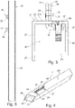
- FIG. 1 shows a perspective view of a piece of furniture or a wall cabinet 1 in a use position with a box-shaped furniture body 2 and a furniture part according to the invention accommodated thereon, which is designed as a top flap 3 , which is shown in an open position relative to the furniture body 2 .
- the furniture part or the top flap 3 has a furniture part frame 16 made up of four frame elements, for example made of aluminum, which are preferably formed with an identical profile shape to one another.
- the furniture part frame 16 is assembled in frame technology or its frame elements are assembled in frame construction.
- the top flap 3 also has an inner element 17 , for example a glass plate, accommodated on the furniture part frame 16 , the inner element 17 being edged or enclosed by the furniture part frame 16 .
- the furniture body 2 comprises two opposing upright side walls 4 and 5, which are connected to a bottom panel 6 at the bottom and to a top panel 7 at the top.
- the furniture body 2 is closed by a rear wall 8 at the rear.
- the upper flap fitting 9 has a first fitting unit 10 on the side wall 4 and a second fitting unit 11 on the side wall 5, which are constructed in the same way but for the functionally correct arrangement on the respective side wall 4 or 5 in relation to the side.
- Each fitting unit 10 and 11 comprises a base unit 12, guide means 13 with a swivel arm arrangement 14.
- the swivel arm arrangement 14 is connected to a side frame element 21 of the furniture part frame 16 via a connection section, which is embodied, for example, as a mounting unit 15 inner side, which faces the narrow end faces of the side walls 4, 5, the underbody 6 and the top floor 7 when the upper flap 3 is closed.
- a corresponding arrangement for connecting the fitting unit 11 to a further lateral frame element 22 of the furniture part frame 16 is provided on the other side of the furniture flap 3 .
- connection section or the assembly unit 15 is present on the frame element 21, which is explained in detail further below.
- the base unit 12 is connected to the mounting unit 15 via a plurality of articulated pivoting arms of the pivoting arm arrangement 14 .
- the assembly unit 15 is firmly but detachably attached to the inside of the top flap 3 or the furniture part frame 16 .
- the base unit 12 is preferably formed from a sheet metal component and comprises a planar, flat or thin base plate and a flat, thin housing element opposite the base plate.
- the housing element is covered with a cover element 18 or a cover plate.
- the base unit 12 there is a face section 19, the outside of which is aligned transversely to the plane of the base plate.
- the relevant pivoting arms of the pivoting arm arrangement 14 reach through a rectangular recess 20 in the end section 19.
- the overall width or thickness of the fitting units 10 and 11 is approximately 12 millimeters, so that a respective material cutout, which is rectangular in the base area, in the side walls 4 and 5 has a depth of approximately 12 millimeters, which means that the remaining base thickness of the side walls 4, 5 is in the range of the respective material recess is about 4 millimeters.
- the furniture part frame 16 is assembled from four square hollow profiles with an identical cross section, for example aluminum hollow profiles.
- an upper frame element and a lower frame element of the furniture part frame 16 are present.
- the upper frame element and the lower frame element connect the two lateral frame elements 21, 22.
- the frame element is connected, for example, with corner connectors (not shown), which engage in abutting end areas or miter areas of the respective frame parts.
- the frame element 21 which is rectangular in cross-section in its basic form, has four walls 23 , 24 , 25 and 26 , the side 26 protruding with an edge 27 somewhat beyond an outer side of the adjacent side 24 .
- the wall 23 is directed inwards towards the end faces of the furniture body 2 and forms an inside of the frame element 21.
- the wall 23 has an outside surface 23a.
- connection section or the assembly unit 15 is in housed in a receiving volume 28 of the frame element 21 which is recessed towards the inside or towards the surface 23a.
- the wall 23 has a material-free window-shaped or strip-shaped opening 29 to an inner volume 30 of the frame element 21 enclosed by the walls 23-26.
- the deepened receiving volume 28 largely consists of a part of the inner volume 30 with a volume fraction that corresponds to the volume of material that is removed from the wall 23 with the opening 29 .
- connection section or the assembly unit 15 is formed in the basic shape of an L from two sheet metal angles 31 and 32 which are firmly connected to one another with two rivets 33 .
- connection section or the assembly unit 15 or the sheet metal angles 31 and 32 form a first leg 34 and a second leg 35.
- the first leg 34 is used to firmly attach the connection section to the wall 23 with a screw connection, for example.
- the screw connection is formed in the first leg 34 by two screw holes 36 with internal threads in the sheet metal bracket 32 and two fastening screws 37 that can be screwed into them. Round holes 38 that match the screw holes 36 are also prepared in the wall 23 .
- the screw hole 36 is present in a sleeve or collar-like section in the sheet metal angle 32, the collar-like section extending through a hole in the other sheet metal angle and being present on the outside of a bore wall of the bore.
- the assembly unit 15 is inserted through the open front end of the frame element 21 into the inner volume 30 for screwing with the second leg 35 in the direction of the wall 23.
- two spaced-apart protruding contact sections 39 and 40 on the second leg 35 protrude through the opening 29 to the outside. Because the contact sections 39 and 40 protrude from the surface 23a of the wall 23, they are advantageously accessible for connection to the respective swivel arm arrangement 14.
- the contact sections 39 and 40 are designed for releasable latching with matching mating sections (not shown) on the end of the associated swivel arm arrangement 14 on the furniture part side.
- the two contact sections 39, 40 each have a latching contour such as an undercut contour or a hook contour for releasable locking.
Landscapes
- Engineering & Computer Science (AREA)
- Mechanical Engineering (AREA)
- Hinges (AREA)
Claims (10)
- Elément de cadre (21) pour un cadre de partie de meuble (16) d'une partie de meuble (3), le cadre de partie de meuble (16) entourant à l'extérieur une zone de surface (17) de la partie de meuble (3), l'élément de cadre (21) présentant une section de raccordement (15), la section de raccordement (15) pouvant être couplée avec un bras pivotant d'un dispositif pivotant (9) qui permet de recevoir la partie de meuble (3) en pivotement sur un corps de meuble (2) d'un meuble (1), et la section de raccordement (15) étant logée de manière noyée dans un volume de réception (28) de l'élément de cadre (21), réalisé en creux par rapport à une face intérieure de l'élément de cadre (21), dans lequel, dans un état fermé de la partie de meuble (3), la face intérieure de l'élément de cadre (21) est tournée vers une face frontale du corps de meuble (2), et le volume de réception (28) étant accessible par l'intermédiaire d'une ouverture (29) sur la face intérieure de l'élément de cadre (21), la section de raccordement (15) présentant des moyens d'arrêt (39, 40) qui peuvent être reliés à un bras pivotant du dispositif pivotant, les moyens d'arrêt (39, 40) étant présents sur une section de la section de raccordement (15) qui passe à travers l'ouverture (29) de l'élément de cadre (21) de sorte que les moyens d'arrêt (39, 40) sont présents en saillie à l'extérieur sur la face intérieure de l'élément de cadre (21), l'élément de cadre (21) étant réalisé sous forme d'élément de profilé creux, une ouverture de fixation (38) étant présente dans la face intérieure, l'ouverture de fixation (38) étant adjacente à l'ouverture (29) vers le volume de réception (28) dans la face intérieure de l'élément de cadre (21), et l'ouverture de fixation (38) servant au passage d'un élément de fixation (37) qui permet de rattacher la section de raccordement (15) à l'élément de cadre (21) restant, la section de raccordement étant rattachée de manière entière noyée par rapport à la face intérieure de l'élément de cadre, seuls les moyens d'arrêt de la section de raccordement étant en saillie dans une mesure souhaitée sur la face intérieure de l'élément de cadre.
- Elément de cadre selon la revendication 1, caractérisé en ce que la face intérieure est formée par une paroi de profilé creux (23) de l'élément de profilé creux.
- Elément de cadre selon l'une quelconque des revendications précédentes, caractérisé en ce que l'élément de cadre (21) est réalisé sous la forme d'un élément de profilé creux carré.
- Elément de cadre selon la revendication 1, caractérisé en ce que l'élément de cadre (21) présente une ouverture allongée (29) dans une paroi de profilé creux (23) de l'élément de profilé creux.
- Elément de cadre selon l'une quelconque des revendications précédentes, caractérisé en ce que l'élément de cadre (21) est réalisé de telle sorte que la section de raccordement (15) peut être rattachée de manière amovible à la partie restante de l'élément de cadre (21).
- Elément de cadre selon l'une quelconque des revendications précédentes, caractérisé en ce que des moyens d'ajustement sont prévus pour ajuster la position de la section de raccordement (15) par rapport à la partie restante de l'élément de cadre (21).
- Elément de cadre selon la revendication 6, caractérisé en ce que les moyens d'ajustement présentent une section de réglage sur la section de raccordement (15) et une vis de réglage (37) passant à travers la section de réglage.
- Elément de cadre selon la revendication 6, caractérisé en ce que les moyens d'ajustement comprennent un ajustement de niveau et/ou un ajustement latéral.
- Elément de cadre selon l'une quelconque des revendications précédentes, caractérisé en ce que la section de raccordement (15) est configurée sous forme d'élément angulaire pourvu d'un premier bras (34) et d'un deuxième bras (35) orienté de manière angulaire par rapport au premier bras (34), le premier bras (34) étant réalisé pour le raccordement à la partie restante de l'élément de cadre (21), et le deuxième bras (35) comprenant les moyens d'arrêt (39, 40).
- Partie de meuble (3) comprenant un cadre de partie de meuble (16) qui présente un élément de cadre (21) selon l'une quelconque des revendications précédentes, le cadre de partie de meuble (16) entourant une zone de surface (17) de la partie de meuble (3).
Applications Claiming Priority (1)
| Application Number | Priority Date | Filing Date | Title |
|---|---|---|---|
| DE202018102087.0U DE202018102087U1 (de) | 2018-04-17 | 2018-04-17 | Rahmenelement eines Möbelteil-Rahmens und Möbelteil |
Publications (2)
| Publication Number | Publication Date |
|---|---|
| EP3556977A1 EP3556977A1 (fr) | 2019-10-23 |
| EP3556977B1 true EP3556977B1 (fr) | 2022-09-28 |
Family
ID=66105004
Family Applications (1)
| Application Number | Title | Priority Date | Filing Date |
|---|---|---|---|
| EP19168310.1A Active EP3556977B1 (fr) | 2018-04-17 | 2019-04-10 | Élément de cadre pour un cadre de meuble et meuble |
Country Status (2)
| Country | Link |
|---|---|
| EP (1) | EP3556977B1 (fr) |
| DE (1) | DE202018102087U1 (fr) |
Citations (1)
| Publication number | Priority date | Publication date | Assignee | Title |
|---|---|---|---|---|
| EP1692358B1 (fr) * | 2003-12-11 | 2008-07-23 | MEPLA-WERKE LAUTENSCHLÄGER GmbH & Co. KG | Logement de charniere pour battants de porte formes, au moins par endroits, par un metal a paroi mince ou par des profiles creux metalliques |
Family Cites Families (8)
| Publication number | Priority date | Publication date | Assignee | Title |
|---|---|---|---|---|
| US2381132A (en) * | 1944-09-26 | 1945-08-07 | Marchand Adolph | Cabinet door fixture |
| DE2052355A1 (de) * | 1966-03-24 | 1972-04-27 | Kunststoff Gmbh | Scharnier für Möbel od.dgl. |
| DE2918478A1 (de) * | 1979-05-08 | 1980-11-13 | Interluebke Kg | Schrankmoebel mit scharnier |
| DE19507523C1 (de) * | 1995-03-03 | 1996-08-14 | Sortimo Int Gmbh | Verschlußklappe mit einer Parallelogramm-Aufhängung sowie Unterbaukasten für Servicefahrzeuge mit einer solchen Verschlußklappe |
| DE19518450A1 (de) * | 1995-05-19 | 1996-11-21 | Bel Air Art Bilderrahmen Gmbh | Möbeltür mit einem Scharnier |
| US7207636B2 (en) * | 2003-09-03 | 2007-04-24 | I.D. Furniture Systems, Inc. | Modular cabinet system |
| US8480189B2 (en) * | 2010-12-10 | 2013-07-09 | Robern, Inc. | Cabinet with offset hinge |
| DE202017102809U1 (de) * | 2017-05-10 | 2018-08-13 | Grass Gmbh & Co. Kg | Vorrichtung zur Bewegung eines an einem Möbelkorpus eines Möbels aufgenommenen Möbelteils |
-
2018
- 2018-04-17 DE DE202018102087.0U patent/DE202018102087U1/de active Active
-
2019
- 2019-04-10 EP EP19168310.1A patent/EP3556977B1/fr active Active
Patent Citations (1)
| Publication number | Priority date | Publication date | Assignee | Title |
|---|---|---|---|---|
| EP1692358B1 (fr) * | 2003-12-11 | 2008-07-23 | MEPLA-WERKE LAUTENSCHLÄGER GmbH & Co. KG | Logement de charniere pour battants de porte formes, au moins par endroits, par un metal a paroi mince ou par des profiles creux metalliques |
Also Published As
| Publication number | Publication date |
|---|---|
| EP3556977A1 (fr) | 2019-10-23 |
| DE202018102087U1 (de) | 2019-07-18 |
Similar Documents
| Publication | Publication Date | Title |
|---|---|---|
| EP3707331B1 (fr) | Paroi latérale d'un corps de meuble avec ferrure et meuble muni d'une paroi latérale | |
| EP3561207B1 (fr) | Moyen de raccordement et partie de meuble | |
| EP3401477B1 (fr) | Meuble | |
| DE202013101519U1 (de) | Duschtür-Baugruppe | |
| DE202018102084U1 (de) | Vorrichtung zur Bewegung eines an einem Möbelkorpus eines Möbels aufgenommenen Möbelteils | |
| EP3613931B1 (fr) | Module de bande destiné au raccordement mobile par charnière autour d'un axe de charnière d'un battant sur un cadre | |
| DE3501048C2 (fr) | ||
| EP0346447A1 (fr) | Plaque de montage de charnieres de meubles | |
| WO1993021413A1 (fr) | Charniere de meuble | |
| AT14999U1 (de) | Band für eine Tür oder ein Fenster | |
| DE202018107035U1 (de) | Schubladen-Verbindungsvorrichtung für eine Verbindung einer Schubladenfront mit einem Schubladenseitenteil | |
| EP3652400B1 (fr) | Dispositif pour animer une partie de meuble d'un mouvement et meuble | |
| EP3401482B1 (fr) | Meuble avec un dispositif de déplacement d'une partie de meuble | |
| EP3401479B1 (fr) | Ferrure d'abattant superieure pour un meuble | |
| EP3556977B1 (fr) | Élément de cadre pour un cadre de meuble et meuble | |
| EP3401478A1 (fr) | Dispositif de déplacement d'une partie de meuble logée sur un corps d'un meuble | |
| EP1454026B1 (fr) | Plaque de montage pour la fixation reglable de charnieres de meuble sur le corps de meubles | |
| EP3025938B1 (fr) | Dispositif de recouvrement pour une face d'un element de paroi | |
| EP3666120B1 (fr) | Dispositif de raccordement de l'avant de tiroir et tiroir | |
| DE69826423T2 (de) | Befestigungselement mit Greifer, insbesondere für einen Einbaubehälter, und entsprechender Einbaubehälter | |
| DE20212055U1 (de) | Bandteil für ein Band für Türen, Fenster u.dgl. | |
| DE102016004915B3 (de) | Beschlag für ein Fenster, Verfahren zum Herstellen des Beschlags sowie entsprechendes Fenster | |
| EP3666121A1 (fr) | Dispositif de raccordement de l'avant de tiroir et tiroir | |
| DE8006248U1 (de) | Ecklager | |
| EP0945574B1 (fr) | Charnière pour portes, fenêtres ou similaires |
Legal Events
| Date | Code | Title | Description |
|---|---|---|---|
| PUAI | Public reference made under article 153(3) epc to a published international application that has entered the european phase |
Free format text: ORIGINAL CODE: 0009012 |
|
| STAA | Information on the status of an ep patent application or granted ep patent |
Free format text: STATUS: THE APPLICATION HAS BEEN PUBLISHED |
|
| AK | Designated contracting states |
Kind code of ref document: A1 Designated state(s): AL AT BE BG CH CY CZ DE DK EE ES FI FR GB GR HR HU IE IS IT LI LT LU LV MC MK MT NL NO PL PT RO RS SE SI SK SM TR |
|
| AX | Request for extension of the european patent |
Extension state: BA ME |
|
| STAA | Information on the status of an ep patent application or granted ep patent |
Free format text: STATUS: REQUEST FOR EXAMINATION WAS MADE |
|
| 17P | Request for examination filed |
Effective date: 20200423 |
|
| RBV | Designated contracting states (corrected) |
Designated state(s): AL AT BE BG CH CY CZ DE DK EE ES FI FR GB GR HR HU IE IS IT LI LT LU LV MC MK MT NL NO PL PT RO RS SE SI SK SM TR |
|
| GRAP | Despatch of communication of intention to grant a patent |
Free format text: ORIGINAL CODE: EPIDOSNIGR1 |
|
| STAA | Information on the status of an ep patent application or granted ep patent |
Free format text: STATUS: GRANT OF PATENT IS INTENDED |
|
| INTG | Intention to grant announced |
Effective date: 20220512 |
|
| GRAS | Grant fee paid |
Free format text: ORIGINAL CODE: EPIDOSNIGR3 |
|
| GRAA | (expected) grant |
Free format text: ORIGINAL CODE: 0009210 |
|
| STAA | Information on the status of an ep patent application or granted ep patent |
Free format text: STATUS: THE PATENT HAS BEEN GRANTED |
|
| AK | Designated contracting states |
Kind code of ref document: B1 Designated state(s): AL AT BE BG CH CY CZ DE DK EE ES FI FR GB GR HR HU IE IS IT LI LT LU LV MC MK MT NL NO PL PT RO RS SE SI SK SM TR |
|
| REG | Reference to a national code |
Ref country code: GB Ref legal event code: FG4D Free format text: NOT ENGLISH |
|
| REG | Reference to a national code |
Ref country code: CH Ref legal event code: EP |
|
| REG | Reference to a national code |
Ref country code: AT Ref legal event code: REF Ref document number: 1521336 Country of ref document: AT Kind code of ref document: T Effective date: 20221015 |
|
| REG | Reference to a national code |
Ref country code: DE Ref legal event code: R096 Ref document number: 502019005739 Country of ref document: DE |
|
| REG | Reference to a national code |
Ref country code: IE Ref legal event code: FG4D Free format text: LANGUAGE OF EP DOCUMENT: GERMAN |
|
| REG | Reference to a national code |
Ref country code: LT Ref legal event code: MG9D |
|
| PG25 | Lapsed in a contracting state [announced via postgrant information from national office to epo] |
Ref country code: SE Free format text: LAPSE BECAUSE OF FAILURE TO SUBMIT A TRANSLATION OF THE DESCRIPTION OR TO PAY THE FEE WITHIN THE PRESCRIBED TIME-LIMIT Effective date: 20220928 Ref country code: RS Free format text: LAPSE BECAUSE OF FAILURE TO SUBMIT A TRANSLATION OF THE DESCRIPTION OR TO PAY THE FEE WITHIN THE PRESCRIBED TIME-LIMIT Effective date: 20220928 Ref country code: NO Free format text: LAPSE BECAUSE OF FAILURE TO SUBMIT A TRANSLATION OF THE DESCRIPTION OR TO PAY THE FEE WITHIN THE PRESCRIBED TIME-LIMIT Effective date: 20221228 Ref country code: LV Free format text: LAPSE BECAUSE OF FAILURE TO SUBMIT A TRANSLATION OF THE DESCRIPTION OR TO PAY THE FEE WITHIN THE PRESCRIBED TIME-LIMIT Effective date: 20220928 Ref country code: LT Free format text: LAPSE BECAUSE OF FAILURE TO SUBMIT A TRANSLATION OF THE DESCRIPTION OR TO PAY THE FEE WITHIN THE PRESCRIBED TIME-LIMIT Effective date: 20220928 Ref country code: FI Free format text: LAPSE BECAUSE OF FAILURE TO SUBMIT A TRANSLATION OF THE DESCRIPTION OR TO PAY THE FEE WITHIN THE PRESCRIBED TIME-LIMIT Effective date: 20220928 |
|
| REG | Reference to a national code |
Ref country code: NL Ref legal event code: MP Effective date: 20220928 |
|
| PG25 | Lapsed in a contracting state [announced via postgrant information from national office to epo] |
Ref country code: HR Free format text: LAPSE BECAUSE OF FAILURE TO SUBMIT A TRANSLATION OF THE DESCRIPTION OR TO PAY THE FEE WITHIN THE PRESCRIBED TIME-LIMIT Effective date: 20220928 Ref country code: GR Free format text: LAPSE BECAUSE OF FAILURE TO SUBMIT A TRANSLATION OF THE DESCRIPTION OR TO PAY THE FEE WITHIN THE PRESCRIBED TIME-LIMIT Effective date: 20221229 |
|
| PG25 | Lapsed in a contracting state [announced via postgrant information from national office to epo] |
Ref country code: SM Free format text: LAPSE BECAUSE OF FAILURE TO SUBMIT A TRANSLATION OF THE DESCRIPTION OR TO PAY THE FEE WITHIN THE PRESCRIBED TIME-LIMIT Effective date: 20220928 Ref country code: RO Free format text: LAPSE BECAUSE OF FAILURE TO SUBMIT A TRANSLATION OF THE DESCRIPTION OR TO PAY THE FEE WITHIN THE PRESCRIBED TIME-LIMIT Effective date: 20220928 Ref country code: PT Free format text: LAPSE BECAUSE OF FAILURE TO SUBMIT A TRANSLATION OF THE DESCRIPTION OR TO PAY THE FEE WITHIN THE PRESCRIBED TIME-LIMIT Effective date: 20230130 Ref country code: ES Free format text: LAPSE BECAUSE OF FAILURE TO SUBMIT A TRANSLATION OF THE DESCRIPTION OR TO PAY THE FEE WITHIN THE PRESCRIBED TIME-LIMIT Effective date: 20220928 Ref country code: CZ Free format text: LAPSE BECAUSE OF FAILURE TO SUBMIT A TRANSLATION OF THE DESCRIPTION OR TO PAY THE FEE WITHIN THE PRESCRIBED TIME-LIMIT Effective date: 20220928 |
|
| PG25 | Lapsed in a contracting state [announced via postgrant information from national office to epo] |
Ref country code: SK Free format text: LAPSE BECAUSE OF FAILURE TO SUBMIT A TRANSLATION OF THE DESCRIPTION OR TO PAY THE FEE WITHIN THE PRESCRIBED TIME-LIMIT Effective date: 20220928 Ref country code: PL Free format text: LAPSE BECAUSE OF FAILURE TO SUBMIT A TRANSLATION OF THE DESCRIPTION OR TO PAY THE FEE WITHIN THE PRESCRIBED TIME-LIMIT Effective date: 20220928 Ref country code: IS Free format text: LAPSE BECAUSE OF FAILURE TO SUBMIT A TRANSLATION OF THE DESCRIPTION OR TO PAY THE FEE WITHIN THE PRESCRIBED TIME-LIMIT Effective date: 20230128 Ref country code: EE Free format text: LAPSE BECAUSE OF FAILURE TO SUBMIT A TRANSLATION OF THE DESCRIPTION OR TO PAY THE FEE WITHIN THE PRESCRIBED TIME-LIMIT Effective date: 20220928 |
|
| REG | Reference to a national code |
Ref country code: DE Ref legal event code: R097 Ref document number: 502019005739 Country of ref document: DE |
|
| PG25 | Lapsed in a contracting state [announced via postgrant information from national office to epo] |
Ref country code: NL Free format text: LAPSE BECAUSE OF FAILURE TO SUBMIT A TRANSLATION OF THE DESCRIPTION OR TO PAY THE FEE WITHIN THE PRESCRIBED TIME-LIMIT Effective date: 20220928 Ref country code: AL Free format text: LAPSE BECAUSE OF FAILURE TO SUBMIT A TRANSLATION OF THE DESCRIPTION OR TO PAY THE FEE WITHIN THE PRESCRIBED TIME-LIMIT Effective date: 20220928 |
|
| PG25 | Lapsed in a contracting state [announced via postgrant information from national office to epo] |
Ref country code: DK Free format text: LAPSE BECAUSE OF FAILURE TO SUBMIT A TRANSLATION OF THE DESCRIPTION OR TO PAY THE FEE WITHIN THE PRESCRIBED TIME-LIMIT Effective date: 20220928 |
|
| PLBE | No opposition filed within time limit |
Free format text: ORIGINAL CODE: 0009261 |
|
| STAA | Information on the status of an ep patent application or granted ep patent |
Free format text: STATUS: NO OPPOSITION FILED WITHIN TIME LIMIT |
|
| 26N | No opposition filed |
Effective date: 20230629 |
|
| PG25 | Lapsed in a contracting state [announced via postgrant information from national office to epo] |
Ref country code: SI Free format text: LAPSE BECAUSE OF FAILURE TO SUBMIT A TRANSLATION OF THE DESCRIPTION OR TO PAY THE FEE WITHIN THE PRESCRIBED TIME-LIMIT Effective date: 20220928 |
|
| REG | Reference to a national code |
Ref country code: CH Ref legal event code: PL |
|
| GBPC | Gb: european patent ceased through non-payment of renewal fee |
Effective date: 20230410 |
|
| PG25 | Lapsed in a contracting state [announced via postgrant information from national office to epo] |
Ref country code: LU Free format text: LAPSE BECAUSE OF NON-PAYMENT OF DUE FEES Effective date: 20230410 |
|
| REG | Reference to a national code |
Ref country code: BE Ref legal event code: MM Effective date: 20230430 |
|
| PG25 | Lapsed in a contracting state [announced via postgrant information from national office to epo] |
Ref country code: MC Free format text: LAPSE BECAUSE OF FAILURE TO SUBMIT A TRANSLATION OF THE DESCRIPTION OR TO PAY THE FEE WITHIN THE PRESCRIBED TIME-LIMIT Effective date: 20220928 |
|
| PG25 | Lapsed in a contracting state [announced via postgrant information from national office to epo] |
Ref country code: GB Free format text: LAPSE BECAUSE OF NON-PAYMENT OF DUE FEES Effective date: 20230410 |
|
| PG25 | Lapsed in a contracting state [announced via postgrant information from national office to epo] |
Ref country code: MC Free format text: LAPSE BECAUSE OF FAILURE TO SUBMIT A TRANSLATION OF THE DESCRIPTION OR TO PAY THE FEE WITHIN THE PRESCRIBED TIME-LIMIT Effective date: 20220928 Ref country code: LI Free format text: LAPSE BECAUSE OF NON-PAYMENT OF DUE FEES Effective date: 20230430 Ref country code: GB Free format text: LAPSE BECAUSE OF NON-PAYMENT OF DUE FEES Effective date: 20230410 Ref country code: FR Free format text: LAPSE BECAUSE OF NON-PAYMENT OF DUE FEES Effective date: 20230430 Ref country code: CH Free format text: LAPSE BECAUSE OF NON-PAYMENT OF DUE FEES Effective date: 20230430 |
|
| REG | Reference to a national code |
Ref country code: IE Ref legal event code: MM4A |
|
| PG25 | Lapsed in a contracting state [announced via postgrant information from national office to epo] |
Ref country code: BE Free format text: LAPSE BECAUSE OF NON-PAYMENT OF DUE FEES Effective date: 20230430 |
|
| PG25 | Lapsed in a contracting state [announced via postgrant information from national office to epo] |
Ref country code: IE Free format text: LAPSE BECAUSE OF NON-PAYMENT OF DUE FEES Effective date: 20230410 |
|
| PG25 | Lapsed in a contracting state [announced via postgrant information from national office to epo] |
Ref country code: IE Free format text: LAPSE BECAUSE OF NON-PAYMENT OF DUE FEES Effective date: 20230410 |
|
| PG25 | Lapsed in a contracting state [announced via postgrant information from national office to epo] |
Ref country code: IT Free format text: LAPSE BECAUSE OF FAILURE TO SUBMIT A TRANSLATION OF THE DESCRIPTION OR TO PAY THE FEE WITHIN THE PRESCRIBED TIME-LIMIT Effective date: 20220928 |
|
| PG25 | Lapsed in a contracting state [announced via postgrant information from national office to epo] |
Ref country code: BG Free format text: LAPSE BECAUSE OF FAILURE TO SUBMIT A TRANSLATION OF THE DESCRIPTION OR TO PAY THE FEE WITHIN THE PRESCRIBED TIME-LIMIT Effective date: 20220928 |
|
| PG25 | Lapsed in a contracting state [announced via postgrant information from national office to epo] |
Ref country code: BG Free format text: LAPSE BECAUSE OF FAILURE TO SUBMIT A TRANSLATION OF THE DESCRIPTION OR TO PAY THE FEE WITHIN THE PRESCRIBED TIME-LIMIT Effective date: 20220928 |
|
| REG | Reference to a national code |
Ref country code: DE Ref legal event code: R082 Ref document number: 502019005739 Country of ref document: DE Representative=s name: RAVENSPAT PATENTANWAELTE PARTNERSCHAFT MBB, DE |
|
| REG | Reference to a national code |
Ref country code: AT Ref legal event code: MM01 Ref document number: 1521336 Country of ref document: AT Kind code of ref document: T Effective date: 20240410 |
|
| PGFP | Annual fee paid to national office [announced via postgrant information from national office to epo] |
Ref country code: DE Payment date: 20250418 Year of fee payment: 7 |
|
| PG25 | Lapsed in a contracting state [announced via postgrant information from national office to epo] |
Ref country code: AT Free format text: LAPSE BECAUSE OF NON-PAYMENT OF DUE FEES Effective date: 20240410 |
|
| PG25 | Lapsed in a contracting state [announced via postgrant information from national office to epo] |
Ref country code: CY Free format text: LAPSE BECAUSE OF FAILURE TO SUBMIT A TRANSLATION OF THE DESCRIPTION OR TO PAY THE FEE WITHIN THE PRESCRIBED TIME-LIMIT; INVALID AB INITIO Effective date: 20190410 |
|
| PG25 | Lapsed in a contracting state [announced via postgrant information from national office to epo] |
Ref country code: HU Free format text: LAPSE BECAUSE OF FAILURE TO SUBMIT A TRANSLATION OF THE DESCRIPTION OR TO PAY THE FEE WITHIN THE PRESCRIBED TIME-LIMIT; INVALID AB INITIO Effective date: 20190410 |
|
| PG25 | Lapsed in a contracting state [announced via postgrant information from national office to epo] |
Ref country code: TR Free format text: LAPSE BECAUSE OF FAILURE TO SUBMIT A TRANSLATION OF THE DESCRIPTION OR TO PAY THE FEE WITHIN THE PRESCRIBED TIME-LIMIT Effective date: 20220928 |