EP3556943A1 - Synthetisches bodenbedeckungssystem zur erosionskontrolle - Google Patents
Synthetisches bodenbedeckungssystem zur erosionskontrolle Download PDFInfo
- Publication number
- EP3556943A1 EP3556943A1 EP19173063.9A EP19173063A EP3556943A1 EP 3556943 A1 EP3556943 A1 EP 3556943A1 EP 19173063 A EP19173063 A EP 19173063A EP 3556943 A1 EP3556943 A1 EP 3556943A1
- Authority
- EP
- European Patent Office
- Prior art keywords
- synthetic
- cover system
- ground cover
- infill
- synthetic ground
- Prior art date
- Legal status (The legal status is an assumption and is not a legal conclusion. Google has not performed a legal analysis and makes no representation as to the accuracy of the status listed.)
- Pending
Links
Images


Classifications
-
- E—FIXED CONSTRUCTIONS
- E02—HYDRAULIC ENGINEERING; FOUNDATIONS; SOIL SHIFTING
- E02D—FOUNDATIONS; EXCAVATIONS; EMBANKMENTS; UNDERGROUND OR UNDERWATER STRUCTURES
- E02D17/00—Excavations; Bordering of excavations; Making embankments
- E02D17/20—Securing of slopes or inclines
- E02D17/202—Securing of slopes or inclines with flexible securing means
-
- E—FIXED CONSTRUCTIONS
- E01—CONSTRUCTION OF ROADS, RAILWAYS, OR BRIDGES
- E01C—CONSTRUCTION OF, OR SURFACES FOR, ROADS, SPORTS GROUNDS, OR THE LIKE; MACHINES OR AUXILIARY TOOLS FOR CONSTRUCTION OR REPAIR
- E01C13/00—Pavings or foundations specially adapted for playgrounds or sports grounds; Drainage, irrigation or heating of sports grounds
- E01C13/08—Surfaces simulating grass ; Grass-grown sports grounds
-
- E—FIXED CONSTRUCTIONS
- E02—HYDRAULIC ENGINEERING; FOUNDATIONS; SOIL SHIFTING
- E02B—HYDRAULIC ENGINEERING
- E02B3/00—Engineering works in connection with control or use of streams, rivers, coasts, or other marine sites; Sealings or joints for engineering works in general
- E02B3/04—Structures or apparatus for, or methods of, protecting banks, coasts, or harbours
- E02B3/12—Revetment of banks, dams, watercourses, or the like, e.g. the sea-floor
- E02B3/122—Flexible prefabricated covering elements, e.g. mats, strips
- E02B3/126—Flexible prefabricated covering elements, e.g. mats, strips mainly consisting of bituminous material or synthetic resins
-
- E—FIXED CONSTRUCTIONS
- E02—HYDRAULIC ENGINEERING; FOUNDATIONS; SOIL SHIFTING
- E02D—FOUNDATIONS; EXCAVATIONS; EMBANKMENTS; UNDERGROUND OR UNDERWATER STRUCTURES
- E02D17/00—Excavations; Bordering of excavations; Making embankments
- E02D17/20—Securing of slopes or inclines
Definitions
- This invention relates to a synthetic ground cover system for erosion control.
- the prior art discloses systems for erosion protection that typically take the form of a combination of synthetic mat and natural grass. Additionally, the prior art generally requires multiple anchors to resist wind uplift and erosion forces on the synthetic mat. Thus, the industry continues to search for improved erosion protection systems which are effective, economical and meet the various local, state and federal environmental laws, rules and guidelines for these systems.
- the present invention provides a new and useful system for covering various types of ground where water and wind erosion protection are needed. More particularly, in a first example form the invention comprises a synthetic ground cover system for erosion control to be placed atop the ground, including a synthetic grass which comprises a composite of one or more geo-textiles tufted with synthetic yarns.
- the synthetic ground cover also includes an infill ballast applied to the synthetic grass and a binding agent applied to the infill to stabilize the sand/soil infill against high velocity water shear forces.
- the binding agent in the synthetic ground cover system for erosion control is cement, grout, lime or the like.
- the binding agent can comprise a polymer.
- the binding agent applied to the infill results in a bound infill having a depth of between about 1 ⁇ 2 inch and about 2 inches.
- the infill is applied to the synthetic grass in a dry condition and then is wetted later to be cured into a bound infill.
- the infill comprises a sand or granular material and the binding agent comprises cement.
- the sand-to-cement ratio is between about 1: 1 and 3:1 by weight.
- the synthetic ground cover also includes at least one filter fabric to be placed on or in the ground and an open grid mesh positioned between the synthetic grass and the filter fabric.
- the at least one filter fabric comprises non-woven synthetic fabric.
- the open grid mesh comprises a synthetic drainage system.
- the synthetic ground cover can include at least one low permeability barrier geomembrane to be placed adjacent the ground.
- the synthetic grass has a density of between about 20 ounces per square yard and 120 ounces per square yard.
- the synthetic grass has fibers with an average length of between about 0.5 and 4 inches that act as reinforcement for the sand/soil infill.
- the synthetic grass has fibers with an average length of between about 1.5 and 3 inches.
- the filter fabric is positioned to be in direct contact with the ground surface and comprises woven synthetic fabric.
- the synthetic fabric can be a non-woven material.
- the invention comprises a method of covering ground for erosion control.
- the method includes the steps of: (a) placing a synthetic grass atop the ground, the synthetic grass having a backing and synthetic grass blades extending therefrom; (b) applying a dry infill ballast to the synthetic grass; and (c) applying a wetting agent to the dry infill to cure the dry infill into a bound infill to stabilize the infill against high velocity water shear forces.
- the dry infill ballast includes cement and the wetting agent comprises water.
- the invention comprises a method of covering ground for erosion control.
- the method includes the steps of: (a) placing a synthetic grass atop the ground, the synthetic grass having a backing and synthetic grass blades extending therefrom; (b) applying a dry infill ballast to the synthetic grass; and (c) applying a wet binding agent to the dry infill to bond the dry infill into a bound infill to stabilize the sand/soil infill against high velocity water shear forces.
- the dry infill ballast includes granular material and the binding agent comprises a polymer.
- the binding agent comprises a cementitious slurry.
- the dry infill ballast can include sand and/or gravel.
- the present invention provides an erosion protection layer for use in embankments, ditches, levees, water channels, downchutes, landfills and other steep topographic ground conditions that are exposed to shear forces of water and winds.
- a synthetic grass is used in combination with a bound/stabilized infill ballast to provide a new and useful ground cover system, while also providing a beneficial erosion protection system that does not require maintenance.
- This combination (sometimes referred to as a composite material) can be used for covering slopes and lining drainage ditches, swales, and downchutes.
- the invention comprises a synthetic ground cover system for erosion control to be placed atop the ground, including a synthetic grass which comprises a composite of one or more geo-textiles tufted with synthetic yarns.
- the synthetic ground cover also includes a stabilized/bound infill ballast applied to the synthetic grass (stabilized against high velocity water shear forces).
- the infill ballast comprises a sand or soil and is bound with a binding agent, such as cement, grout, lime or the like.
- the artificial turf provides for separation of the sand infill from the ground below and the turf blades act as structural reinforcement of the sand infill while providing an aesthetically pleasing surface.
- the sand infill on top is stabilized against washing or blowing away by a binding agent applied to the sand infill, which generally has the effect of cementing or bonding together the sand.
- This allows the invention to resist large shear forces from water or wind.
- the bonding strength need not be incredibly high. Indeed, it is not necessary to achieve a structural strength as great as concrete, for example. Instead, it is sufficient that the binding agent merely hold the sand together against erosive forces of wind and water.
- the sand/soil is bound to the other sand particles and/or to the synthetic turf blades by the binder.
- Figure 1 is a schematic, sectional view of an example synthetic ground cover system 110 for erosion control according the present invention and showing the surface of the soil S covered with the present ground cover erosion control system.
- the system includes a synthetic turf 140 which includes a backing 142 and synthetic turf blades 141 secured to the backing.
- a stabilized/bound sand/soil infill 160 is placed in the bottom of the synthetic turf 140 above the backing 142.
- the soil S can be topped with a sand subgrade, gravel subgrade, or intermediate cover before laying down the synthetic ground cover system 110 for erosion control, as desired.
- the synthetic turf 140 is placed more or less directly atop the soil S .
- the system can also be provided with additional elements interposed between the soil S and the turf 140.
- the synthetic turf 140 is used as a principal component of the synthetic ground cover system. It can be constructed using a knitting machine or tufting machine that may use, for example, over 1,000 needles to produce a turf width of about 15 feet.
- the synthetic turf includes synthetic grass blades 141 which comprise polyethylene monofilament and/or slit-film fibrillated and non-fibrillated fibers tufted to have a blade length of between about 0.5 inches and 4 inches. Other polymers can be used for the synthetic grass blades, as desired.
- the synthetic grass blades 141 are tufted to have a blade length of between about 1.5 inches and 3 inches. Most preferably, the synthetic grass blades 141 are tufted to have a blade length of about 1.5 inches.
- the synthetic grass blades 141 are tufted to have a density of between about 20 ounces/square yard and about 120-ounces/square yard.
- the synthetic grass blades have a thickness of at least about 100 microns.
- the synthetic grass blades 141 are tufted into the substrate or backing 142 comprising a synthetic woven or non-woven fabric.
- this backing can be a single ply backing or can be a multi-ply backing, as desired.
- a geo filter can be secured to the substrate to reinforce the substrate and better secure the synthetic grass blades.
- the chemical composition of the synthetic turf components should be selected to resist degradation by exposure to sunlight, which generates heat and contains ultraviolet radiation.
- the polymer yarns should not become brittle when subjected to low temperatures.
- the selection of the synthetic grass color and texture should be aesthetically pleasing.
- the actual grass-like components preferably consist of green polyethylene fibers 141 of about 1.5 to about 2.5 inches in length tufted into a woven or non-woven geotextile(s). For added strength in severely steep sideslopes, an additional geo filter component backing can be tufted for improving dimensional stability.
- the polyethylene grass filaments 141 preferably have an extended operational life of at least 15 years.
- a sand/soil layer 160 of about 0.5 to about 2.0 inches is placed atop the synthetic turf as infill to ballast the material and protect the system against wind uplift as well as to provide dimensional stability.
- the infill is between about 0.5 and 1 inches.
- the sand/soil layer provides additional protection of the geotextiles against ultraviolet light.
- the sand/soil ballast is bonded with cement, grout, lime or another binding agent in order to resist the shear forces of water and wind on steep sideslopes, drainage ditches and downchutes.
- the synthetic turf 140 is first placed over the ground and then the sand/soil infill is spread over the synthetic turf in dry form.
- the dry infill material to easily and effectively settle into the bottom of the synthetic turf.
- the infill is watered (as by spraying water over the turf) and allowed to cure into a hardened, bound infill layer.
- the sand/soil infill is bound to itself and is bound to the individual blades of the synthetic turf.
- the individual blades of the turf act as anchors and help hold the bound infill in place.
- the "sand/soil” infill includes true sands (including silica sands, quartz sands, etc), soils, clays, mixtures thereof, etc. It also includes things that are like sand or soil. For example, granular tailings from rock quarries could be employed (things like granular marble, quartz, granite, etc). Also, small gravel can be used as the "sand/soil" infill. In this regard, it is preferred that the infill be inorganic in nature so as to be very stable and long-lasting. But organic granular material could be employed in certain applications. Moreover, the binding agent could be inorganic or organic. Preferably, the binding agent is inorganic (again, for stability and long life).
- binding agents such as organic binders
- polymer-based binders could be used (for example, a urethane product).
- a spray-on binding agent has come to market for binding small gravel in pathways under the brand name "Klingstone”and sold by Klingstone, Inc. of Waynesville, NC.
- a recipe of about three parts sand and one part cement works well as a dry infill. Once wetted and cured, this bound sand infill provides an excellent ballast against lifting of the turf by wind and also resists damage or erosion from wind or rain or high water flows.
- a recipe of about equal parts sand and cement also works well, as do ratios between these two examples.
- recipes closer to 3:1 are generally more economical but have lower strength, while recipes closer to 1:1 are generally stronger, but more expensive.
- a recipe of 2:2:1 of sand/cement/lime works well also.
- instead of lime one can use fly ash.
- the present invention can be used even where high concentrated flows are expected (e.g.. downchutes, large drainage swales).
- a binding agent such as cement, grout, lime, etc. This creates a more or less grouted or bound sand/soil infill 160 to resist the shear forces of water flow and wind.
- This invention combines the use of a synthetic grass to provide a pleasant visual appearance, erosion protection with very minimal maintenance.
- the invention incorporates a bound infill that, together with the synthetic grass, can handle very rapid water run-offs.
- the cover system of this invention can be installed on very steep slopes which typically occur in embankments, levees, dams, downchutes, landfills and stockpiles.
- the system can be used as erosion control material that can resist large shear forces of water or wind.
- the system can take other forms.
- the system can comprise a membrane with a drainage layer overlain by synthetic turf having cemented (stabilized) infill using any of the binding agents described herein and the like.
- a bottom layer includes a structured low permeable membrane (optionally with textured or spikes on bottom side and drainage studs on top side) and a top layer.
- the top layer can include turf (with, for example, 1.5 inch pile height) and an infill of sand, lime and cement mixture.
- the infill can be 0.75 inches of the mixture.
- FIG 2 is a schematic, sectional view of a synthetic ground cover system 210 for erosion control according to a second example of the present invention, shown without an open mesh grid at the bottom of the system.
- the example cover system 210 for erosion control shown in Figure 2 is used to control erosion of the soil S .
- the system 210 includes a lower filter fabric (geofilter) 220, an open grid mesh or geo-net 230 and a synthetic turf 240.
- the synthetic turf 240 includes a backing 242 and blades 241 secured to the backing.
- a stabilized/bound sand/soil infill 260 is placed in the bottom of the synthetic turf 240 above the backing 242.
- the soil S can be topped with a sand subgrade, gravel subgrade, or intermediate cover before laying down the synthetic ground cover system 210 for erosion control, as desired.
- the lower filter fabric 220 comprises a woven or non-woven synthetic fabric.
- the lower filter fabric 220 can be replaced with a barrier geomembrane with low permeability.
- Figures 3A and 3B depict a synthetic ground cover system 310 for erosion control according to a third example of the present invention, shown without an open mesh grid at the bottom of the system.
- the example cover system 310 for erosion control shown in these figures is used to control erosion of the soil S .
- the system 310 includes an impermeable geomembrane 350 and a synthetic turf 340.
- the impermeable geomembrane 350 is a polymeric sheet with slender spikes on the bottom surface and cleat-like or stud-like nubs on the top surface. For example, see upper nubs 351-354 and spikes 357-359.
- the lower spikes help anchor the impermeable geomembrane to the soil S and the upper nubs help anchor the synthetic turf 340 to the impermeable geomembrane 350.
- the upper nubs also provide a transmissive drainage layer or space in which water can flow over the membrane beneath the synthetic turf.
- the synthetic turf 340 includes a backing 342 and blades 341 secured to the backing. A stabilized/bound sand/soil infill 360 is placed in the bottom of the synthetic turf 340 above the backing 342.
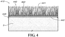
- FIG 4 is a schematic, sectional view of another synthetic ground cover system 410 for erosion control according to the present invention, shown with a reinforcement layer on the backing of the synthetic turf.
- the example cover system 410 for erosion control shown in Figure 4 is used to control erosion of the soil S .
- the system 410 includes a synthetic turf 440 which includes a backing 442 and blades 441 secured to the backing.
- the backing 442 can be a single ply backing or a multi-ply backing.
- a urethane barrier 443 is applied to the underside of the backing 442 and acts to both strengthen the backing and the connection between the blades 441 and the backing 442.
- the urethane barrier 443 also makes the backing 442 generally impermeable to water.
- a stabilized/bound sand/soil infill 460 is placed in the bottom of the synthetic turf 440 above the backing 442.
- Figures 5A and 5B show the example embodiment of Figure 1 applied over a terrain of varying slopes.
- This synthetic ground cover system 110 has the capacity to handle high-intensity precipitation and avoids erosion of the sand/soil infill ballast and/or the shearing stresses on the turf ranging from 1 pound per square foot to more than 25 pounds per square foot.
- the cover system reduces construction costs, reduces annual operation and maintenance costs while providing superior and reliable/consistent aesthetics. It also reduces the need for expensive riprap channels and drainage benches, with substantially no erosion or siltation problems, even during severe weather. It is a good choice in sensitive areas where soil erosion and sedimentation are major concerns because soil loss is substantially reduced. It also eliminates the need for siltation ponds and associated environmental construction impacts. It allows for steeper slopes, because there will be a reduced risk of soil stability problems.
Landscapes
- Engineering & Computer Science (AREA)
- General Engineering & Computer Science (AREA)
- Mining & Mineral Resources (AREA)
- Civil Engineering (AREA)
- Structural Engineering (AREA)
- Life Sciences & Earth Sciences (AREA)
- General Life Sciences & Earth Sciences (AREA)
- Paleontology (AREA)
- Ocean & Marine Engineering (AREA)
- Mechanical Engineering (AREA)
- Environmental & Geological Engineering (AREA)
- Architecture (AREA)
- Cultivation Of Plants (AREA)
- Road Paving Structures (AREA)
Applications Claiming Priority (3)
| Application Number | Priority Date | Filing Date | Title |
|---|---|---|---|
| US201161451839P | 2011-03-11 | 2011-03-11 | |
| EP12716805.2A EP2683875B1 (de) | 2011-03-11 | 2012-03-11 | Synthetisches bodenbelagsystem mit bindungsfüllmaterial zur erosionskontrolle |
| PCT/US2012/028673 WO2012125513A1 (en) | 2011-03-11 | 2012-03-11 | Synthetic ground cover system with binding infill for erosion control |
Related Parent Applications (1)
| Application Number | Title | Priority Date | Filing Date |
|---|---|---|---|
| EP12716805.2A Division EP2683875B1 (de) | 2011-03-11 | 2012-03-11 | Synthetisches bodenbelagsystem mit bindungsfüllmaterial zur erosionskontrolle |
Publications (1)
| Publication Number | Publication Date |
|---|---|
| EP3556943A1 true EP3556943A1 (de) | 2019-10-23 |
Family
ID=46001732
Family Applications (2)
| Application Number | Title | Priority Date | Filing Date |
|---|---|---|---|
| EP19173063.9A Pending EP3556943A1 (de) | 2011-03-11 | 2012-03-11 | Synthetisches bodenbedeckungssystem zur erosionskontrolle |
| EP12716805.2A Active EP2683875B1 (de) | 2011-03-11 | 2012-03-11 | Synthetisches bodenbelagsystem mit bindungsfüllmaterial zur erosionskontrolle |
Family Applications After (1)
| Application Number | Title | Priority Date | Filing Date |
|---|---|---|---|
| EP12716805.2A Active EP2683875B1 (de) | 2011-03-11 | 2012-03-11 | Synthetisches bodenbelagsystem mit bindungsfüllmaterial zur erosionskontrolle |
Country Status (7)
| Country | Link |
|---|---|
| US (1) | US9163375B2 (de) |
| EP (2) | EP3556943A1 (de) |
| CA (1) | CA2829964C (de) |
| ES (1) | ES2734477T3 (de) |
| MX (1) | MX337616B (de) |
| PT (1) | PT2683875T (de) |
| WO (1) | WO2012125513A1 (de) |
Families Citing this family (40)
| Publication number | Priority date | Publication date | Assignee | Title |
|---|---|---|---|---|
| EP2616193B1 (de) * | 2010-09-13 | 2020-12-16 | Watershed Geosynthetics LLC. | Windbeständige synthetische abdeckung |
| US20130243367A1 (en) * | 2012-03-16 | 2013-09-19 | William Redvers Belisle | Fiber Optic Turf Blade Contact and Movement Sensor |
| US9540777B1 (en) * | 2012-04-25 | 2017-01-10 | Christopher Tetrault | Method for cooling of synthetic turf |
| US9315961B2 (en) * | 2012-05-15 | 2016-04-19 | North American Green, Inc. | Self-anchoring turf reinforcement mat and reusable sediment filtration mat |
| US20140270992A1 (en) * | 2013-03-13 | 2014-09-18 | Michael Ayers | Method for installing synthetic ground cover with infill |
| CN103314687B (zh) * | 2013-06-03 | 2015-06-24 | 宁夏大学 | 悬挂式散长草草方格固沙机 |
| US9365991B2 (en) | 2013-10-10 | 2016-06-14 | Watershed Geosynthetics Llc | Formed in place filled structure with synthetic turf |
| US11214931B2 (en) * | 2013-11-15 | 2022-01-04 | Christopher John Fellars | Artificial turf edging system and method |
| US10472775B2 (en) * | 2013-11-15 | 2019-11-12 | Christopher John Fellars | Artificial turf edging system and method |
| US9790647B2 (en) * | 2013-11-15 | 2017-10-17 | Christopher John Fellars | Artificial turf edging system and method |
| EP2883988B1 (de) | 2013-12-13 | 2016-04-13 | BFS Europe NV | Kunstrasen für Landschaft und Sport |
| PL3080346T3 (pl) | 2013-12-13 | 2019-11-29 | Bfs Europe Nv | Struktura tuftowana do zastosowań krajobrazowych i sportowych |
| US10190267B2 (en) | 2013-12-13 | 2019-01-29 | Bfs Europe Nv | Artificial turf for landscape and sports |
| US10370799B2 (en) | 2013-12-13 | 2019-08-06 | Dfs Europe Nv | Tufted structure for landscape and sports |
| TWI593858B (zh) * | 2014-02-21 | 2017-08-01 | 分水嶺地工合成材料有限責任公司 | 用於侵蝕控制之具不透性襯墊及結合填充物之合成地面被覆系統 |
| GB201414012D0 (en) * | 2014-08-07 | 2014-09-24 | Allen Richard A | Processing of artificial turf |
| CH710334A2 (de) * | 2014-11-04 | 2016-05-13 | Geobrugg Ag | Netzsystem vorzugsweise für eine Böschungssicherung. |
| CN104818721B (zh) * | 2015-03-24 | 2017-05-17 | 中国地质大学(北京) | 一种适用于陡壁深坑型废弃矿山地质环境治理方法 |
| US20170058464A1 (en) * | 2015-09-02 | 2017-03-02 | Tarkett Inc. | Protective binding layer |
| CA2959976A1 (en) | 2016-03-08 | 2017-09-08 | Ron Froh | Waste disposal closure system |
| US11031903B2 (en) | 2016-11-09 | 2021-06-08 | Watershed Solar, Llc | Solar energy system for use with tufted geosynthetics on sloping ground |
| AU2018236265B2 (en) | 2017-03-14 | 2021-08-05 | Watershed Geosynthetics Llc | Solar energy system for use with tufted geosynthetics |
| CA3005122A1 (en) | 2017-05-16 | 2018-11-16 | Robert Ziegan | Surface system and method of installation |
| WO2018237043A1 (en) | 2017-06-20 | 2018-12-27 | Watershed Solar, Llc | Integrated solar photovoltaic module mounting system |
| US11277091B2 (en) | 2017-06-20 | 2022-03-15 | Watershed Solar LLC | Integrated photovoltaic module mounting system for use with tufted geosynthetics |
| US20190017231A1 (en) * | 2017-07-11 | 2019-01-17 | Watershed Geosynthetics Llc | Synthetic ground cover system for erosion protection |
| US20190153687A1 (en) * | 2017-11-17 | 2019-05-23 | Watershed Geosynthetics Llc | Geoturf tubes and improvements to conventional geotubes |
| CA3083945A1 (en) | 2017-11-28 | 2019-06-06 | Watershed Geosynthetics Llc | Stabilized water flow control ground cover |
| WO2019108687A1 (en) * | 2017-11-28 | 2019-06-06 | Watershed Geosynthetics Llc | Water flow control ground cover |
| US20190222162A1 (en) * | 2018-01-12 | 2019-07-18 | Watershed Solar LLC | Elongate member mounting system for securing photovoltaic module to ground cover system |
| CN108951666A (zh) * | 2018-07-06 | 2018-12-07 | 中国地质调查局西安地质调查中心 | 一种以铁尾砂为集料的边坡加固及生态修复技术 |
| US20200071887A1 (en) * | 2018-08-31 | 2020-03-05 | Watershed Geosynthetics Llc | Tufted Geotextile With Increased Shear Resistance To Hydraulic Infill Displacement And Dry-Flow Loading |
| US10794013B2 (en) | 2018-10-29 | 2020-10-06 | Columbia Insurance Company | Playing surface assemblies and systems, and methods of making and using same |
| US11746476B2 (en) * | 2019-11-25 | 2023-09-05 | Capillary Concrete, Llc | Subsurface irrigation system for a sports field |
| WO2021127451A1 (en) * | 2019-12-19 | 2021-06-24 | Watershed Geosynthetics Llc | Synthetic turf ground cover system for erosion protection |
| BE1028215B1 (nl) * | 2020-04-16 | 2021-11-23 | Jan Peter DERLUYN | Middel voor bescherming tegen erosie en werkwijze voor het vervaardigen ervan |
| WO2021216806A1 (en) | 2020-04-23 | 2021-10-28 | Watershed Geosynthetics, LLC | Synthetic turf joining system with water channel and method of joining synthetic turf |
| MX2023001908A (es) * | 2020-08-14 | 2023-06-29 | Watershed Holdings LLC | Geomembrana resistente al corte que usa acoplamiento mecánico. |
| WO2022104191A1 (en) * | 2020-11-16 | 2022-05-19 | Agru/America, Inc. | Polymeric waterproofing membrane |
| AU2022264712A1 (en) * | 2021-04-25 | 2023-12-14 | Watershed Geosynthetics Llc | Tufted geotextile with understory for shear resistance to hydraulic and dry-flow infill displacement |
Citations (8)
| Publication number | Priority date | Publication date | Assignee | Title |
|---|---|---|---|---|
| WO1991000939A1 (en) * | 1989-07-13 | 1991-01-24 | Knowles Albert H | A building product |
| US5876745A (en) | 1993-08-27 | 1999-03-02 | Nitto Denko Corporation | Method for preparing a medical adhesive sheet |
| WO2002020903A1 (en) * | 2000-09-05 | 2002-03-14 | Fieldturf Inc. | Artificial grass for landscaping |
| US6472041B1 (en) * | 2000-02-28 | 2002-10-29 | Richard L. Burke | Monolithic surfacing system and method for making same |
| US6858272B2 (en) | 2001-03-14 | 2005-02-22 | Troy Squires | Horizontally draining, pre-engineered synthetic turf field |
| US6877932B2 (en) | 2001-07-13 | 2005-04-12 | Fieldturf (Ip) Inc. | Drainage system and method for artificial grass using spacing grid |
| JP2005299125A (ja) * | 2004-04-08 | 2005-10-27 | Shiima Consultant:Kk | 人工芝敷設構造 |
| US20080193226A1 (en) * | 2007-02-13 | 2008-08-14 | David Michael Jones | Retaining wall having artificial grass reinforcing fabric |
Family Cites Families (7)
| Publication number | Priority date | Publication date | Assignee | Title |
|---|---|---|---|---|
| WO1989001076A1 (en) | 1987-07-23 | 1989-02-09 | Noel Peter John Mogford | Turf surfaces |
| US5258217A (en) * | 1991-05-28 | 1993-11-02 | A/A Manufacturing, Inc. | Landfill liner |
| CA2363822C (en) * | 1997-03-10 | 2007-01-30 | Fieldturf Holdings Inc. | Synthetic turf |
| US20030118755A1 (en) * | 2001-12-21 | 2003-06-26 | Motz Joseph E. | Filled synthetic turf with ballast layer |
| US7128497B2 (en) * | 2003-12-02 | 2006-10-31 | Daluise Daniel A | Horizontally draining artificial turf system |
| US7682105B2 (en) * | 2006-09-14 | 2010-03-23 | Ayers Michael R | Cover system for waste sites and environmental closures |
| ITPD20070123A1 (it) | 2007-04-04 | 2008-10-05 | Unieco Green S P A | Metodo per la realizzazione di un campo sportivo in erba artificiale e campo sportivo cosi' ottenuto |
-
2012
- 2012-03-11 EP EP19173063.9A patent/EP3556943A1/de active Pending
- 2012-03-11 CA CA2829964A patent/CA2829964C/en active Active
- 2012-03-11 US US13/417,275 patent/US9163375B2/en active Active
- 2012-03-11 ES ES12716805T patent/ES2734477T3/es active Active
- 2012-03-11 WO PCT/US2012/028673 patent/WO2012125513A1/en not_active Ceased
- 2012-03-11 PT PT12716805T patent/PT2683875T/pt unknown
- 2012-03-11 EP EP12716805.2A patent/EP2683875B1/de active Active
- 2012-03-11 MX MX2013010411A patent/MX337616B/es active IP Right Grant
Patent Citations (9)
| Publication number | Priority date | Publication date | Assignee | Title |
|---|---|---|---|---|
| WO1991000939A1 (en) * | 1989-07-13 | 1991-01-24 | Knowles Albert H | A building product |
| US5876745A (en) | 1993-08-27 | 1999-03-02 | Nitto Denko Corporation | Method for preparing a medical adhesive sheet |
| US6472041B1 (en) * | 2000-02-28 | 2002-10-29 | Richard L. Burke | Monolithic surfacing system and method for making same |
| WO2002020903A1 (en) * | 2000-09-05 | 2002-03-14 | Fieldturf Inc. | Artificial grass for landscaping |
| US6946181B2 (en) | 2000-09-05 | 2005-09-20 | Fieldturf Inc. | Artificial grass for landscaping |
| US6858272B2 (en) | 2001-03-14 | 2005-02-22 | Troy Squires | Horizontally draining, pre-engineered synthetic turf field |
| US6877932B2 (en) | 2001-07-13 | 2005-04-12 | Fieldturf (Ip) Inc. | Drainage system and method for artificial grass using spacing grid |
| JP2005299125A (ja) * | 2004-04-08 | 2005-10-27 | Shiima Consultant:Kk | 人工芝敷設構造 |
| US20080193226A1 (en) * | 2007-02-13 | 2008-08-14 | David Michael Jones | Retaining wall having artificial grass reinforcing fabric |
Also Published As
| Publication number | Publication date |
|---|---|
| EP2683875A1 (de) | 2014-01-15 |
| CA2829964C (en) | 2018-04-03 |
| PT2683875T (pt) | 2019-08-23 |
| WO2012125513A1 (en) | 2012-09-20 |
| US9163375B2 (en) | 2015-10-20 |
| MX337616B (es) | 2016-03-10 |
| EP2683875B1 (de) | 2019-05-08 |
| ES2734477T3 (es) | 2019-12-10 |
| MX2013010411A (es) | 2014-07-30 |
| CA2829964A1 (en) | 2012-09-20 |
| US20120230777A1 (en) | 2012-09-13 |
Similar Documents
| Publication | Publication Date | Title |
|---|---|---|
| EP2683875B1 (de) | Synthetisches bodenbelagsystem mit bindungsfüllmaterial zur erosionskontrolle | |
| US9587364B2 (en) | Synthetic ground cover system with impermeable backing and binding infill for erosion control | |
| US10689824B2 (en) | Synthetic ground cover system for erosion protection for use with or without a sand/soil ballast | |
| US8240959B1 (en) | Geosynthetic tufted drain barrier | |
| US20140270992A1 (en) | Method for installing synthetic ground cover with infill | |
| US20190360162A1 (en) | Synthetic ground cover system for erosion protection | |
| US20150118418A1 (en) | Geocomposite covering | |
| CN106894311A (zh) | 一种海绵型城市透水沥青路面 | |
| KR100966468B1 (ko) | 보강매트와 유공관이 결합된 무 배수로 투수 기층구조 의 시공방법. | |
| Leão et al. | Natural fibres for geotextiles | |
| EP3102742B1 (de) | Synthetisches bodenbedeckungssystem zur erosionskontrolle | |
| KR100966473B1 (ko) | 비노출 배수로의 기층구조 및 유공관을 포함하는 비노출 배수로의 시공방법 | |
| KR20150021098A (ko) | 수변구조물 강화공법 | |
| HK1231149A1 (en) | Synthetic ground cover system for erosion control | |
| HK1231149B (en) | Synthetic ground cover system for erosion control | |
| CN113863335A (zh) | 治理流砂地层排水沟道边坡坍塌与沟水净化回用的方法 | |
| CN207659813U (zh) | 一种透水混凝土路面施工结构 | |
| Board | Save nature use coir | |
| JPH03224583A (ja) | 地下貯水層を有するゴルフ用グリーン構造 | |
| Mishra | Use of Geo-Synthetics in Soil Reinforcement/Road constructions | |
| TM | ENGINEERING USE OF GEOTEXTILES | |
| Dhanya et al. | Feasibility studies on applicability of low cost materials for farm road construction and slope protection | |
| KR20050117149A (ko) | 섬유고화판 및 흙포장공법을 이용한 수로표면 포장공법 |
Legal Events
| Date | Code | Title | Description |
|---|---|---|---|
| PUAI | Public reference made under article 153(3) epc to a published international application that has entered the european phase |
Free format text: ORIGINAL CODE: 0009012 |
|
| STAA | Information on the status of an ep patent application or granted ep patent |
Free format text: STATUS: THE APPLICATION HAS BEEN PUBLISHED |
|
| AC | Divisional application: reference to earlier application |
Ref document number: 2683875 Country of ref document: EP Kind code of ref document: P |
|
| AK | Designated contracting states |
Kind code of ref document: A1 Designated state(s): AL AT BE BG CH CY CZ DE DK EE ES FI FR GB GR HR HU IE IS IT LI LT LU LV MC MK MT NL NO PL PT RO RS SE SI SK SM TR |
|
| STAA | Information on the status of an ep patent application or granted ep patent |
Free format text: STATUS: REQUEST FOR EXAMINATION WAS MADE |
|
| 17P | Request for examination filed |
Effective date: 20200423 |
|
| RBV | Designated contracting states (corrected) |
Designated state(s): AL AT BE BG CH CY CZ DE DK EE ES FI FR GB GR HR HU IE IS IT LI LT LU LV MC MK MT NL NO PL PT RO RS SE SI SK SM TR |
|
| STAA | Information on the status of an ep patent application or granted ep patent |
Free format text: STATUS: EXAMINATION IS IN PROGRESS |
|
| 17Q | First examination report despatched |
Effective date: 20200612 |
|
| P01 | Opt-out of the competence of the unified patent court (upc) registered |
Effective date: 20230607 |
|
| RIN1 | Information on inventor provided before grant (corrected) |
Inventor name: URRUTIA, JOSE Inventor name: AYERS, MICHAEL |