EP3556901B1 - Vacuum arc source - Google Patents
Vacuum arc source Download PDFInfo
- Publication number
- EP3556901B1 EP3556901B1 EP18168526.4A EP18168526A EP3556901B1 EP 3556901 B1 EP3556901 B1 EP 3556901B1 EP 18168526 A EP18168526 A EP 18168526A EP 3556901 B1 EP3556901 B1 EP 3556901B1
- Authority
- EP
- European Patent Office
- Prior art keywords
- cathode
- vacuum arc
- arc source
- anode
- source according
- Prior art date
- Legal status (The legal status is an assumption and is not a legal conclusion. Google has not performed a legal analysis and makes no representation as to the accuracy of the status listed.)
- Active
Links
Images

Classifications
-
- H—ELECTRICITY
- H01—ELECTRIC ELEMENTS
- H01J—ELECTRIC DISCHARGE TUBES OR DISCHARGE LAMPS
- H01J37/00—Discharge tubes with provision for introducing objects or material to be exposed to the discharge, e.g. for the purpose of examination or processing thereof
- H01J37/32—Gas-filled discharge tubes
- H01J37/32009—Arrangements for generation of plasma specially adapted for examination or treatment of objects, e.g. plasma sources
- H01J37/32055—Arc discharge
-
- C—CHEMISTRY; METALLURGY
- C23—COATING METALLIC MATERIAL; COATING MATERIAL WITH METALLIC MATERIAL; CHEMICAL SURFACE TREATMENT; DIFFUSION TREATMENT OF METALLIC MATERIAL; COATING BY VACUUM EVAPORATION, BY SPUTTERING, BY ION IMPLANTATION OR BY CHEMICAL VAPOUR DEPOSITION, IN GENERAL; INHIBITING CORROSION OF METALLIC MATERIAL OR INCRUSTATION IN GENERAL
- C23C—COATING METALLIC MATERIAL; COATING MATERIAL WITH METALLIC MATERIAL; SURFACE TREATMENT OF METALLIC MATERIAL BY DIFFUSION INTO THE SURFACE, BY CHEMICAL CONVERSION OR SUBSTITUTION; COATING BY VACUUM EVAPORATION, BY SPUTTERING, BY ION IMPLANTATION OR BY CHEMICAL VAPOUR DEPOSITION, IN GENERAL
- C23C14/00—Coating by vacuum evaporation, by sputtering or by ion implantation of the coating forming material
- C23C14/06—Coating by vacuum evaporation, by sputtering or by ion implantation of the coating forming material characterised by the coating material
- C23C14/067—Borides
-
- C—CHEMISTRY; METALLURGY
- C23—COATING METALLIC MATERIAL; COATING MATERIAL WITH METALLIC MATERIAL; CHEMICAL SURFACE TREATMENT; DIFFUSION TREATMENT OF METALLIC MATERIAL; COATING BY VACUUM EVAPORATION, BY SPUTTERING, BY ION IMPLANTATION OR BY CHEMICAL VAPOUR DEPOSITION, IN GENERAL; INHIBITING CORROSION OF METALLIC MATERIAL OR INCRUSTATION IN GENERAL
- C23C—COATING METALLIC MATERIAL; COATING MATERIAL WITH METALLIC MATERIAL; SURFACE TREATMENT OF METALLIC MATERIAL BY DIFFUSION INTO THE SURFACE, BY CHEMICAL CONVERSION OR SUBSTITUTION; COATING BY VACUUM EVAPORATION, BY SPUTTERING, BY ION IMPLANTATION OR BY CHEMICAL VAPOUR DEPOSITION, IN GENERAL
- C23C14/00—Coating by vacuum evaporation, by sputtering or by ion implantation of the coating forming material
- C23C14/22—Coating by vacuum evaporation, by sputtering or by ion implantation of the coating forming material characterised by the process of coating
- C23C14/24—Vacuum evaporation
- C23C14/32—Vacuum evaporation by explosion; by evaporation and subsequent ionisation of the vapours, e.g. ion-plating
- C23C14/325—Electric arc evaporation
-
- C—CHEMISTRY; METALLURGY
- C23—COATING METALLIC MATERIAL; COATING MATERIAL WITH METALLIC MATERIAL; CHEMICAL SURFACE TREATMENT; DIFFUSION TREATMENT OF METALLIC MATERIAL; COATING BY VACUUM EVAPORATION, BY SPUTTERING, BY ION IMPLANTATION OR BY CHEMICAL VAPOUR DEPOSITION, IN GENERAL; INHIBITING CORROSION OF METALLIC MATERIAL OR INCRUSTATION IN GENERAL
- C23C—COATING METALLIC MATERIAL; COATING MATERIAL WITH METALLIC MATERIAL; SURFACE TREATMENT OF METALLIC MATERIAL BY DIFFUSION INTO THE SURFACE, BY CHEMICAL CONVERSION OR SUBSTITUTION; COATING BY VACUUM EVAPORATION, BY SPUTTERING, BY ION IMPLANTATION OR BY CHEMICAL VAPOUR DEPOSITION, IN GENERAL
- C23C14/00—Coating by vacuum evaporation, by sputtering or by ion implantation of the coating forming material
- C23C14/22—Coating by vacuum evaporation, by sputtering or by ion implantation of the coating forming material characterised by the process of coating
- C23C14/56—Apparatus specially adapted for continuous coating; Arrangements for maintaining the vacuum, e.g. vacuum locks
- C23C14/564—Means for minimising impurities in the coating chamber such as dust, moisture, residual gases
-
- H—ELECTRICITY
- H01—ELECTRIC ELEMENTS
- H01J—ELECTRIC DISCHARGE TUBES OR DISCHARGE LAMPS
- H01J37/00—Discharge tubes with provision for introducing objects or material to be exposed to the discharge, e.g. for the purpose of examination or processing thereof
- H01J37/32—Gas-filled discharge tubes
- H01J37/32431—Constructional details of the reactor
- H01J37/32532—Electrodes
- H01J37/32541—Shape
-
- H—ELECTRICITY
- H01—ELECTRIC ELEMENTS
- H01J—ELECTRIC DISCHARGE TUBES OR DISCHARGE LAMPS
- H01J37/00—Discharge tubes with provision for introducing objects or material to be exposed to the discharge, e.g. for the purpose of examination or processing thereof
- H01J37/32—Gas-filled discharge tubes
- H01J37/32431—Constructional details of the reactor
- H01J37/32532—Electrodes
- H01J37/3255—Material
-
- H—ELECTRICITY
- H01—ELECTRIC ELEMENTS
- H01J—ELECTRIC DISCHARGE TUBES OR DISCHARGE LAMPS
- H01J37/00—Discharge tubes with provision for introducing objects or material to be exposed to the discharge, e.g. for the purpose of examination or processing thereof
- H01J37/32—Gas-filled discharge tubes
- H01J37/32431—Constructional details of the reactor
- H01J37/32532—Electrodes
- H01J37/32614—Consumable cathodes for arc discharge
-
- H—ELECTRICITY
- H01—ELECTRIC ELEMENTS
- H01J—ELECTRIC DISCHARGE TUBES OR DISCHARGE LAMPS
- H01J2237/00—Discharge tubes exposing object to beam, e.g. for analysis treatment, etching, imaging
- H01J2237/32—Processing objects by plasma generation
- H01J2237/33—Processing objects by plasma generation characterised by the type of processing
- H01J2237/332—Coating
Definitions
- the invention concerns a vacuum arc source for arc evaporation of Boride with the features of the preamble of claim 1 and use of such a vacuum arc source.
- WO 2011/137472 A1 discloses a TiB 2 target which contains fractions of one or more metals from the group consisting of iron, nickel, cobalt and chromium and also carbon having specific mean grain size of the TiB 2 grains and carbon content
- EP0577246 as well as US2013220800 are both disclosing a boride (TiB2) vacuum arc source with: a cathode of e.g TiB2, an anode (Cu in first document), a body surrounding the cathode and permitting the confinement of the arcs (shields 4 in first Document, and ring 16 in the second one).
- Destructions of TiB 2 -cathodes upon arcing is assumed to be caused by a relatively high thermal expansion coefficient. Local heating of the TiB 2 -cathode by the arc spot leads to high stress, with resulting cracking, upon a temperature gradient.
- the purpose of the invention is to provide a vacuum arc source for arc evaporation of Boride that can be used continuously or for longer periods of time than vacuum arc sources according to the prior art.
- an inventive vacuum arc source there are dissipated arc discharges (as no magnets need be used) leading to less current density and therefore less thermal shock decreasing risk of cracking of cathode. It is achieved that a coating produced using the inventive vacuum arc source is - at least substantially - free from impurities.
- anode Placing the anode near the cathode results in intensive anode heating. Choosing an anode, the material of which is at least 90 at-% (preferably more than 99 at-%) of the same chemical composition as the cathode, cathode contamination of anode material, and resulting unintentional impurity incorporation during materials synthesis, is prevented.
- the cathode is made of TiB 2 , ZrB 2 , VB 2 , TaB 2 , CrB 2 , NbB 2 , W 2 B 5 or WB 2 , HfB 2 , AlB 2 , MoB 2 , or MoB, or mixtures thereof.
- the invention provides for ignition of the discharge at another material with subsequent movement of the arc spot to the Boride cathode.
- the cathode is surrounded by a body made of a material which is less preferred by arc discharge compared to the cathode.
- the invention increases the time a vacuum arc source for arc evaporation of Boride can be used by eliminating cathode destruction due to electrical and/or mechanical effects occurring during the ignition and/or operation of the arc.
- a magnet is used for keeping the arc at the operational cathode surface. Without the magnet and without a body, arc spots start to go to the side of the cathode, where generated metallic flux can disrupt source insulators or the spot can die. Both these effects influence the process stability.
- the invention does not need the use of a magnet, in other words, during operation of the vacuum arc source, motion of the arc discharge is governed by electric field lines extending between cathode and anode and preferably there are no magnets guiding the arc discharge.
- a magnet (which is typically used in prior sources), needs not be used. The absence of the magnet may lead to arc spots going to the edges of the cathode, where they die, and interrupt the deposition process.
- the here proposed body of a material of a higher cathode potential contains the arc in the operational area of the cathode surface limited by the cylinder edges. With no source magnet present, an increase in the strength of the electric field on sharp crystal grains on a Boride-cathode surface supports ignition of simultaneously operating arc spots of a lower spot current. This reduces the temperature gradient at the operational cathode surface and reduces the accompanying stress and a probability of cathode destruction.
- Mo Molybdenum
- TiB 2 a potential around 30 V for the same conditions as used for, e. g., TiB 2 . Comparing the resulting power (potential multiplied with the arc current), in this invention Mo or alloys thereof are preferably used as a material for the body surrounding the cathode.
- Other possible materials are Tungsten, Tantalum, Niobium, or alloys thereof, or electrically insulating ceramics based on Al 2 O 3 , ZrO 2 , BN.
- a shape of the cathode is prismatic or cylindrical and/or a shape of the body is prismatic or cylindrical (having an opening for the cathode), wherein it is preferred that the shape of the cathode and the shape of the body are at least substantially the same. It should be understood, however, that the aforementioned shaped of the cathode can be modified in such a way that the cathode shows tapering towards the arc surface.
- a cylindrical shape of the cathode and a hollow-cylindrical shape of the body allow rotation of the cathode.
- a maximum gap between cathode and body is below 1 Millimeter, preferably below 0,5 Millimeter. Although gaps of such small dimensions are acceptable it is preferred that the body abuts the cathode.
- the height of the body With respect to a height of the body relative to a height of the cathode it is not necessary - although possible - that they are the same. It is sufficient if it is provided that the height of the body is at least 30 % of the height of the cathode.
- the anode - in a view onto the arc surface of the cathode - covers the end face of the body (with the possible exception of a slit for a trigger pin of an ignition system) - leaving an aperture allowing transport of a material flux from the arc surface of the cathode.
- the body surrounding the cathode not only prevents glowing of the arc at the cathode border, but also protect the operational cathode surface from electrical and mechanical damaging effects accompanying ignition of the arc.
- the arc discharge is ignited by a pneumatic system based on a brief touch of the cathode surface by a trigger pin.
- the ignition current flowing through the trigger is typically in the range of tens of amperes, and the contact area is relatively small.
- the trigger pin can be arranged to touch the body surrounding the cathode instead of the cathode itself (e. g. the length of the trigger pin can be adjusted).
- a radial width of the body should be greater than a diameter of the trigger pin thus ensuring reliable ignition.
- the edge of the body then serves as the place for the arc ignition process (only if the material of the body is electrically conductive, this would not work e. g. with electrically insulating materials such as the beforementioned ceramics) with subsequent movement of the discharge to the cathode, where the arc preferentially glows. Tests by the applicant showed that erosion of the body is insignificant compared to the cathode. When using a body made of Molybdenum, diagnostics of plasma generated from the assembly and the resulting films showed no traces of Molybdenum.
- Similar increase in field strength can be achieved by reduction of the cathode-anode distance, by placing the system anode as close to the cathode surface as possible.
- the material flux from the cathode surface, for such configuration, is proposed to go through the anode aperture.
- a short cathode-anode distance results in evaporation of the anode. This may result in deposition of anode material onto the cathode surface, and unintentional incorporation of contaminations during materials synthesis.
- a cooling system for the anode can be utilized, however, in the invention this is not necessary since at least 90 at-% of the material of the anode is of the same chemical composition as the cathode.
- the vacuum arc source according to the invention can be uses for PVD deposition of thin-film-coatings, preferably for cutting and forming tools.
- the proposed vacuum arc source has been successfully tested for a TiB 2 -cathode. Every assembly part was tested separately as well as together. For all performed experiments an arc current equal to 100 Amp has been used in a chamber with operational pressure of 10 -5 Torr.
- a plasma analyzer EQP from Hiden LTD was placed at 35 cm from a TiB 2 -cathode with a diameter of 59 mm surrounded by a Mo cylinder with an inner diameter of about 59 mm and an outer diameter of about 63 mm. Ignition was performed more than 10 times per minute for approximately 1 hour. It was found that ignition of the arc on Mo and subsequent movement to the TiB 2 -cathode was assured for at least 90 % of the attempts. Plasma diagnostics of the resulting material flux showed non-significant amount of Mo. The experiment also showed that with the body surrounding the TiB 2 -cathode, there is no destruction of the cathode surface by the trigger pin. However, from time to time, the arc spot was still able to stick locally.
- a vacuum arc source consisting of the TiB 2 -cathode, the Mo cylinder and the TiB 2 disc anode with a slit for arc ignition was also tested.
- the complete assembly showed a stable arc ignition process and smooth and stable arc plasma generation. Erosion of the operational cathode surface was found smooth and uniform. Sticking of the arc spot and an accompanying destruction of the cathode was not detected for the whole time of the experiment, about 2 hours.
- the performed plasma diagnostic of the generated material flux could be reproduced at different times during the experiment, or between different experiments performed under the same conditions.
- the cathode-assembly according to the invention and/or a vacuum arc source according to the invention can be uses for PVD deposition of coatings for cutting and forming tools.
- a hollow shape of the body is chosen correspondingly, e. g. for a cylindrical cathode the body is in the shape of a hollow cylinder, for a conical cathode the body is in the shape of a hollow cone, for a prismatic cathode the body is in the shape of a hollow prism etc.
- Figure 1 shows a cathode-assembly for arc evaporation of TiB 2 with a cathode 1 made of TiB 2 , the cathode 1 being surrounded by a body 2 made of a material (here: Mo) which is less preferred by arc discharge compared to the TiB 2 -cathode 1.
- An ignition system 3 comprising a trigger pin 4 is shown.
- Figure 2 shows a vacuum arc source for arc evaporation of TiB 2 using the cathode-assembly of Figure 1 .
- the body 2 in form of a Mo cylinder protects the cathode 1 from undesired effects accompanying ignition of the arc and, at the same time, it keeps the arc spot at the operational cathode surface.
- the anode 5 has the shape of a disk with an aperture 7 for transport of the generated material flux to a substrate. It can also be noted that performed experiments showed that arc spots ignited below the anode 5 tend to go to the cathode area below the anode aperture.
- the disk is provided with a slit 6 for the trigger pin 4 providing arc discharge ignition such that the trigger pin 4 can pass through the plane of the disk to touch the body 2.
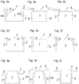
- FIGS 3a to 3i show different possible configurations of cathode 1, body 2 and anode 5.
- cathode 1, body 2 and anode 5 are in the form of rotating bodies:
- the cathode 1 is in the shape of a cylinder having a groove for the body 2 which is in the shape of a hollow cylinder.
- the cathode 1 is in the shape of a (truncated) cone and the body 2 is in the shape of a hollow (truncated) cone.
- the cathode 1 is in the shape of a cylinder which is tapering towards the arc surface.
- the anode 5 is in the form of a ring.
- a height H B of the body 2 is at least 30 % of a height H C of the cathode 1.
- the body 2 abuts a mantle surface of the cathode 1.
- a small gap between body 2 and cathode 1 below 1 Millimeter, preferably below 0,5 Millimeter would be acceptable.
- a top or end surface of the body 2 is coplanar with the arc surface of the cathode 1.
- the body 2 is coplanar with an outer rim of the arc surface of the cathode 1.
- an inner, central region of the arc surface of the cathode 1 lies below the outer rim of the arc surface of the cathode 1.
Landscapes
- Chemical & Material Sciences (AREA)
- Engineering & Computer Science (AREA)
- Organic Chemistry (AREA)
- Materials Engineering (AREA)
- Mechanical Engineering (AREA)
- Metallurgy (AREA)
- Chemical Kinetics & Catalysis (AREA)
- Physics & Mathematics (AREA)
- Plasma & Fusion (AREA)
- Analytical Chemistry (AREA)
- Physical Vapour Deposition (AREA)
- High-Tension Arc-Extinguishing Switches Without Spraying Means (AREA)
- Discharge Heating (AREA)
- Inorganic Insulating Materials (AREA)
Description
- The invention concerns a vacuum arc source for arc evaporation of Boride with the features of the preamble of
claim 1 and use of such a vacuum arc source. - To date, there is no reproducible synthesis of Borides, in particular TiB2, from arc evaporation, and from the reported few attempts on use of TiB2-cathodes for thin film synthesis, extensive instability, cracking, and cathode failure can be concluded. In use of prior industrial arc sources, it is observed that cathode erosion is typically not uniform, with a high probability of sticking of the arc spot locally on the cathode surface with subsequent cathode destruction and termination of the deposition process after only minutes of operation (i. e. bad cathode utilization).
- Deposition of TiB2 films by the vacuum arc process at a TiB2-cathode is not well described in literature. This is mainly limited to laboratory use, primarily due to challenges associated with materials synthesis such as extensive instability, cracking, and cathode failure (O. Knotek, F. Löffler, M. Böhmer, R. Breidenbach and C. Stöbel, "Ceramic cathodes for arc-physical vapour deposition: development and application," Surface and Coatings Technology, vol. 49, pp. 263-267, 1991.).
- Hypothetical routes for improving the process stability, such as applying a suitable magnetic field, or working in a reactive atmosphere (O. Knotek, F. Löffler, M. Böhmer, R. Breidenbach and C. Stöbel, "Ceramic cathodes for arc-physical vapour deposition: development and application," Surface and Coatings Technology, vol. 49, pp. 263-267, 1991.), or through usage of a pulsed arc, have been suggested (J. Treglio, S. Trujillo and A. Perry, "Deposition of TiB2 at low temperature with low residual stress by a vacuum arc plasma source," Surface and Coatings Technology, vol. 61, pp. 315-319, 1993.).
- These routes remain to be confirmed, although an improved arc process stability has been reported for use of a TiB2-cathode in N2 (H. Fager, J. Andersson, J. Jensen, J. Lu and L. Hultman, "Thermal stability and mechanical properties of amorphous coatings in the Ti-B-Si-Al-N system grown by cathodic arc evaporation from TiB2, Tb3Al67, and Ti85Si15 cathodes," J. Vac. Sci. Technol. A., vol. 32, no. 6, p. 061508, 2014.).
- It has also been observed that removal of an external magnetic field seems to lead to dissipation of the arc spots and an increased active area of the cathode, with resulting reduced overheating and a somewhat stabilized plasma generation (I. Zhirkov, A. Petruhins, L.-A. Naslund, S. Kolozsvari, P. Polcik, and J. Rosen "Vacuum arc plasma generation and thin film deposition from a TiB2 cathode", Applied Physics Letters 107, 184103 (2015).).
-
WO 2011/137472 A1 discloses a TiB2 target which contains fractions of one or more metals from the group consisting of iron, nickel, cobalt and chromium and also carbon having specific mean grain size of the TiB2 grains and carbon content -
EP0577246 as well asUS2013220800 are both disclosing a boride (TiB2) vacuum arc source with: a cathode of e.g TiB2, an anode (Cu in first document), a body surrounding the cathode and permitting the confinement of the arcs (shields 4 in first Document, and ring 16 in the second one). - Destructions of TiB2-cathodes upon arcing is assumed to be caused by a relatively high thermal expansion coefficient. Local heating of the TiB2-cathode by the arc spot leads to high stress, with resulting cracking, upon a temperature gradient.
- The purpose of the invention is to provide a vacuum arc source for arc evaporation of Boride that can be used continuously or for longer periods of time than vacuum arc sources according to the prior art.
- This is being achieved by a vacuum arc source with the features of
claim 1 and use of such a vacuum arc source. Embodiments of the invention are defined in the dependent claims. - According to the invention there are provided:
- a cathode made of at least 90 at-% of Boride, in particular made of more than 98 at-% of Boride
- a body made of a material which is less preferred by arc discharge compared to the cathode, the body surrounding the cathode in such a way that during operation of the vacuum arc source, movement of an arc on an arc surface of the cathode is limited by the body
- an anode, which is preferably in the shape of a disk, at least 90 at-% of the material of the anode being of the same chemical composition as the cathode.
- In an inventive vacuum arc source there are dissipated arc discharges (as no magnets need be used) leading to less current density and therefore less thermal shock decreasing risk of cracking of cathode. It is achieved that a coating produced using the inventive vacuum arc source is - at least substantially - free from impurities.
- Placing the anode near the cathode results in intensive anode heating. Choosing an anode, the material of which is at least 90 at-% (preferably more than 99 at-%) of the same chemical composition as the cathode, cathode contamination of anode material, and resulting unintentional impurity incorporation during materials synthesis, is prevented.
- Preferably, the cathode is made of TiB2, ZrB2, VB2, TaB2, CrB2, NbB2, W2B5 or WB2, HfB2, AlB2, MoB2, or MoB, or mixtures thereof.
- Due to the striving of any physical process for the lowest cost of power, arc ignition on a cathode consisting of two or more regions of distinctly different elemental compositions, results in preferential arc glowing on the material which is able to provide the lowest glowing cathode potential, even if the initial arc was ignited on a material with higher potential. Therefore, the invention provides for ignition of the discharge at another material with subsequent movement of the arc spot to the Boride cathode. For this purpose, the cathode is surrounded by a body made of a material which is less preferred by arc discharge compared to the cathode.
- In the present invention, destruction of the operational cathode surface is prevented by an increase in the active area of the arc spot and thereby an improved heat distribution. The invention increases the time a vacuum arc source for arc evaporation of Boride can be used by eliminating cathode destruction due to electrical and/or mechanical effects occurring during the ignition and/or operation of the arc.
- By surrounding the cathode by a body made of a material which is less preferred by arc discharge the presence of arc spots at the cathode edges can be prevented thus increasing process stability. In the prior art a magnet is used for keeping the arc at the operational cathode surface. Without the magnet and without a body, arc spots start to go to the side of the cathode, where generated metallic flux can disrupt source insulators or the spot can die. Both these effects influence the process stability. The invention does not need the use of a magnet, in other words, during operation of the vacuum arc source, motion of the arc discharge is governed by electric field lines extending between cathode and anode and preferably there are no magnets guiding the arc discharge.
- In the inventive vacuum arc source, designed to provide conditions for dissipation of the arc spots, stable plasma generation and consequently uniform cathode erosion, a magnet (which is typically used in prior sources), needs not be used. The absence of the magnet may lead to arc spots going to the edges of the cathode, where they die, and interrupt the deposition process. The here proposed body of a material of a higher cathode potential contains the arc in the operational area of the cathode surface limited by the cylinder edges. With no source magnet present, an increase in the strength of the electric field on sharp crystal grains on a Boride-cathode surface supports ignition of simultaneously operating arc spots of a lower spot current. This reduces the temperature gradient at the operational cathode surface and reduces the accompanying stress and a probability of cathode destruction.
- As any physical process strives for the lowest cost of power, and as performed experiments show that the arc discharge glows at a cathode with a cathode - anode potential lower than 25 V, the material should provide a significantly higher potential. One such material is Molybdenum (Mo) with a potential around 30 V for the same conditions as used for, e. g., TiB2. Comparing the resulting power (potential multiplied with the arc current), in this invention Mo or alloys thereof are preferably used as a material for the body surrounding the cathode. Other possible materials are Tungsten, Tantalum, Niobium, or alloys thereof, or electrically insulating ceramics based on Al2O3, ZrO2, BN.
- Preferably, a shape of the cathode is prismatic or cylindrical and/or a shape of the body is prismatic or cylindrical (having an opening for the cathode), wherein it is preferred that the shape of the cathode and the shape of the body are at least substantially the same. It should be understood, however, that the aforementioned shaped of the cathode can be modified in such a way that the cathode shows tapering towards the arc surface. A cylindrical shape of the cathode and a hollow-cylindrical shape of the body allow rotation of the cathode.
- With respect to the radial arrangement of the body relative to the cathode, it is preferred that a maximum gap between cathode and body is below 1 Millimeter, preferably below 0,5 Millimeter. Although gaps of such small dimensions are acceptable it is preferred that the body abuts the cathode.
- With respect to the axial arrangement of the body relative to the cathode there are different alternative possibilities:
- the body might be arranged to protrude axially over the arc surface of the cathode
- the cathode might be arranged to protrude axially over an end surface of the body
- the arc surface of the cathode and an end surface of the body might be arranged to be coplanar
- With respect to a height of the body relative to a height of the cathode it is not necessary - although possible - that they are the same. It is sufficient if it is provided that the height of the body is at least 30 % of the height of the cathode.
- In a preferred embodiment, the anode - in a view onto the arc surface of the cathode - covers the end face of the body (with the possible exception of a slit for a trigger pin of an ignition system) - leaving an aperture allowing transport of a material flux from the arc surface of the cathode.
- It is preferred that a minimal distance between
- the cathode and the anode or
- the body and the anode
- The body surrounding the cathode not only prevents glowing of the arc at the cathode border, but also protect the operational cathode surface from electrical and mechanical damaging effects accompanying ignition of the arc. In many traditional industrial DC arc sources, the arc discharge is ignited by a pneumatic system based on a brief touch of the cathode surface by a trigger pin. The ignition current flowing through the trigger is typically in the range of tens of amperes, and the contact area is relatively small. As a result, arc ignition on a cathode according to the prior art tend to lead to a partial destruction of the surface around the trigger pin, eventually preventing the pin to touch the cathode and making ignition of the arc impossible.
- In a preferred embodiment the trigger pin can be arranged to touch the body surrounding the cathode instead of the cathode itself (e. g. the length of the trigger pin can be adjusted). In this case a radial width of the body should be greater than a diameter of the trigger pin thus ensuring reliable ignition. The edge of the body then serves as the place for the arc ignition process (only if the material of the body is electrically conductive, this would not work e. g. with electrically insulating materials such as the beforementioned ceramics) with subsequent movement of the discharge to the cathode, where the arc preferentially glows. Tests by the applicant showed that erosion of the body is insignificant compared to the cathode. When using a body made of Molybdenum, diagnostics of plasma generated from the assembly and the resulting films showed no traces of Molybdenum.
- In a recent publication (I. Zhirkov, A. Petruhins, L.-A. Naslund, S. Kolozsvari, P. Polcik, and J. Rosen "Vacuum arc plasma generation and thin film deposition from a TiB2 cathode", Applied Physics Letters 107, 184103 (2015)), it was suggested that the crystalline structure with related surface features of a TiB2 cathode induce dissipation of the arc spots (unless hindered by e. g. steering through a magnetic field), through an increase in strength of the electric field at the TiB2 crystal grains, which improves the stability of the arc plasma generation. Similar increase in field strength can be achieved by reduction of the cathode-anode distance, by placing the system anode as close to the cathode surface as possible. The material flux from the cathode surface, for such configuration, is proposed to go through the anode aperture. However, a short cathode-anode distance results in evaporation of the anode. This may result in deposition of anode material onto the cathode surface, and unintentional incorporation of contaminations during materials synthesis. To avoid this, a cooling system for the anode can be utilized, however, in the invention this is not necessary since at least 90 at-% of the material of the anode is of the same chemical composition as the cathode.
- Testing of the inventive cathode assembly demonstrated a much-improved stability compared to prior art source schemas. Further development is based on improved arc dissipation through an increase in the strength of the electric field at the cathode surface crystal grains. Any electrical discharge, as well as the here considering arc discharge, glows between at least two electrodes - cathode and anode (one of them can be virtual). The industrial arc sources typically have no separate anode, instead the chamber walls play the role of the anode, with a resulting typical large cathode - anode distance. Still, it is known, that the strength of the electrical field is determined by the anode-cathode distance. On the other hand, it is also known, that plasma shields the discharge electrodes from each another and almost all potential drop takes place near the cathode. In an embodiment of the invention, it is proposed, that a reduction of the cathode-anode distance will increase the density of the plasma in the cathode-anode gap and consequently facilitate ignition of the arc spot and enhance spot dissipation.
- The vacuum arc source according to the invention can be uses for PVD deposition of thin-film-coatings, preferably for cutting and forming tools.
- The proposed vacuum arc source has been successfully tested for a TiB2-cathode. Every assembly part was tested separately as well as together. For all performed experiments an arc current equal to 100 Amp has been used in a chamber with operational pressure of 10-5 Torr.
- For testing arc ignition by using a body in the form of a Mo cylinder and checking the possible presence of Mo in the resulting material flux from the arc source, a plasma analyzer EQP from Hiden LTD was placed at 35 cm from a TiB2-cathode with a diameter of 59 mm surrounded by a Mo cylinder with an inner diameter of about 59 mm and an outer diameter of about 63 mm. Ignition was performed more than 10 times per minute for approximately 1 hour. It was found that ignition of the arc on Mo and subsequent movement to the TiB2-cathode was assured for at least 90 % of the attempts. Plasma diagnostics of the resulting material flux showed non-significant amount of Mo. The experiment also showed that with the body surrounding the TiB2-cathode, there is no destruction of the cathode surface by the trigger pin. However, from time to time, the arc spot was still able to stick locally.
- Using a TiB2 disc as anode has also been tested separately, with plasma analysis performed with the analyzer at the distance of 35 cm. The anode disk thickness was 5 mm, the diameter was 150 mm. The aperture within the anode was 55 mm for the here used 63 mm cathode. The distance between the cathode and the anode in this experiment was set to 2 mm. For the trigger pin, there was a slit in the anode allowing ignition of the arc by the trigger pin. The performed experiment showed a positive influence of the presence of the anode on the stability of the arc discharge. Plasma diagnostics did not show changes in the plasma properties and/or composition of the generated flux as compared to plasma generated without an anode. However, experiments showed that in the absence of the Mo cylinder, the arc frequently died at the edges of the cathode.
- A vacuum arc source consisting of the TiB2-cathode, the Mo cylinder and the TiB2 disc anode with a slit for arc ignition was also tested. The complete assembly showed a stable arc ignition process and smooth and stable arc plasma generation. Erosion of the operational cathode surface was found smooth and uniform. Sticking of the arc spot and an accompanying destruction of the cathode was not detected for the whole time of the experiment, about 2 hours. The performed plasma diagnostic of the generated material flux could be reproduced at different times during the experiment, or between different experiments performed under the same conditions.
- The cathode-assembly according to the invention and/or a vacuum arc source according to the invention can be uses for PVD deposition of coatings for cutting and forming tools.
- It is preferred that for a given shape of the cathode, a hollow shape of the body is chosen correspondingly, e. g. for a cylindrical cathode the body is in the shape of a hollow cylinder, for a conical cathode the body is in the shape of a hollow cone, for a prismatic cathode the body is in the shape of a hollow prism etc.
- Embodiments of the invention are shown in the figures:
- Fig. 1
- an embodiment of an inventive cathode-assembly
- Fig. 2
- an embodiment of an inventive vacuum arc source
- Fig. 3a-3i
- different possible configurations of cathode, body and anode
-
Figure 1 shows a cathode-assembly for arc evaporation of TiB2 with acathode 1 made of TiB2, thecathode 1 being surrounded by abody 2 made of a material (here: Mo) which is less preferred by arc discharge compared to the TiB2-cathode 1. Anignition system 3 comprising atrigger pin 4 is shown. -
Figure 2 shows a vacuum arc source for arc evaporation of TiB2 using the cathode-assembly ofFigure 1 . Thebody 2 in form of a Mo cylinder protects thecathode 1 from undesired effects accompanying ignition of the arc and, at the same time, it keeps the arc spot at the operational cathode surface. - The
anode 5 has the shape of a disk with anaperture 7 for transport of the generated material flux to a substrate. It can also be noted that performed experiments showed that arc spots ignited below theanode 5 tend to go to the cathode area below the anode aperture. - The disk is provided with a
slit 6 for thetrigger pin 4 providing arc discharge ignition such that thetrigger pin 4 can pass through the plane of the disk to touch thebody 2. -
Figures 3a to 3i show different possible configurations ofcathode 1,body 2 andanode 5. In all Figures,cathode 1,body 2 andanode 5 are in the form of rotating bodies: InFigures 3a to 3f , thecathode 1 is in the shape of a cylinder having a groove for thebody 2 which is in the shape of a hollow cylinder. InFigures 3g and 3h , thecathode 1 is in the shape of a (truncated) cone and thebody 2 is in the shape of a hollow (truncated) cone. InFigure 3i thecathode 1 is in the shape of a cylinder which is tapering towards the arc surface. InFigures 3a to 3i theanode 5 is in the form of a ring. - In all Figures, a height HB of the
body 2 is at least 30 % of a height HC of thecathode 1. - In all Figures, the
body 2 abuts a mantle surface of thecathode 1. However, a small gap betweenbody 2 andcathode 1 below 1 Millimeter, preferably below 0,5 Millimeter would be acceptable. - In
Figure 3a to 3c a top or end surface of thebody 2 is coplanar with the arc surface of thecathode 1. - In
Figure 3d thebody 2 protrudes over the arc surface of thecathode 1. - In
Figures 3e and 3g to 3i thecathode 1 protrudes over thebody 2. - In
Figure 3f thebody 2 is coplanar with an outer rim of the arc surface of thecathode 1. In a radial direction towards the center an inner, central region of the arc surface of thecathode 1 lies below the outer rim of the arc surface of thecathode 1. -
- 1
- cathode
- 2
- body surrounding the cathode
- 3
- ignition system
- 4
- trigger pin
- 5
- anode
- 6
- slit in the anode
- 7
- aperture of anode
- HB
- height of body
- HC
- height of cathode
Claims (16)
- Vacuum arc source for arc evaporation of Boride, comprising:- a cathode (1) made of at least 90 at-% of Boride, in particular made of more than 98 at-% of Boride- an anode (5)- a body (2) made of a material which is less preferred by arc discharge compared to the cathode (1), the body (2) surrounding the cathode (1) in such a way that during operation of the vacuum arc source, movement of an arc on an arc surface of the cathode (1) is limited by the body (2)characterized in that
at least 90 at-% of the material of the anode (5) is of the same chemical composition as the cathode (1). - Vacuum arc source according to claim 1, wherein the anode (5) is in the shape of a disk.
- Vacuum arc source according to at least one of the preceding claims, wherein the cathode (1) is made of TiB2, ZrB2, VB2, TaB2, CrB2, NbB2, W2B5 or WB2, HfB2, AlB2, MoB2, or MoB, or mixtures thereof.
- Vacuum arc source according to at least one of the preceding claims, wherein a shape of the cathode (1) is prismatic or cylindrical and/or a shape of the body (2) is prismatic or cylindrical, wherein it is preferred that the shape of the cathode (1) and the shape of the body (2) are at least substantially the same.
- Vacuum arc source according to the preceding claim, wherein the cathode (1) is tapering towards the arc surface.
- Vacuum arc source according to at least one of the preceding claims, wherein a maximum gap between cathode (1) and body (2) is below 1 Millimeter, preferably below 0,5 Millimeter and it is preferred that the body (2) abuts the cathode (1).
- Vacuum arc source according to at least one of the preceding claims, wherein- the body (2) protrudes axially over the arc surface of the cathode (1) or- the cathode (1) protrudes axially over an end surface of the body (2) or- the arc surface of the cathode (1) and an end surface of the body (2) are coplanar.
- Vacuum arc source according to at least one of the preceding claims, wherein a height (HB) of the body (2) is at least 30 % of a height (HC) of the cathode (1).
- Vacuum arc source according to at least one of the preceding claims, wherein the body (2) surrounding the cathode (1) is made of- Molybdenum, Tungsten, Tantalum, Niobium, or alloys thereof, or- electrically insulating ceramics based on Al2O3, ZrO2, BN.
- Vacuum arc source according to at least one of the preceding claims, wherein more than 99 at-% of the material of the anode (5) is of the same chemical composition as the material of the cathode (1).
- Vacuum arc source according to at least one of the preceding claims, wherein the anode (5) - in a view onto the arc surface of the cathode (1) - covers the end face of the body (2) - with the possible exception of a slit (6) for a trigger pin (4) of an ignition system - leaving an aperture (7) allowing transport of a material flux from the arc surface of the cathode (1).
- Vacuum arc source according to at least one of the preceding claims, wherein a minimal distance between- the cathode (1) and the anode (5) or- the body (2) and the anode (5)is between 0,5 Millimeter and 10 Millimeter, preferably between 1 Millimeter and 5 Millimeter.
- Vacuum arc source according to at least one of the preceding claims, wherein an ignition system of the vacuum arc source comprises a trigger pin (4), the trigger pin (4) being arranged to touch the body (2) surrounding the cathode (1).
- Vacuum arc source according to the preceding claim, wherein the body (2) has a radial width which is greater than a diameter of the trigger pin (4) thus allowing reliable ignition.
- Vacuum arc source according to at least one of the preceding claims, wherein during operation of the vacuum arc source, motion of the arc discharge is governed by electric field lines extending between cathode (1) and anode (5) and preferably there are no magnets for guiding the arc discharge.
- Use of a vacuum arc source according to at least one of the preceding claims for PVD deposition of thin-film-coatings, preferably for cutting tools or forming tools.
Priority Applications (7)
| Application Number | Priority Date | Filing Date | Title |
|---|---|---|---|
| EP18168526.4A EP3556901B1 (en) | 2018-04-20 | 2018-04-20 | Vacuum arc source |
| CN201980026736.7A CN112352063B (en) | 2018-04-20 | 2019-03-13 | Vacuum arc source |
| KR1020207029276A KR102446609B1 (en) | 2018-04-20 | 2019-03-13 | vacuum arc source |
| US17/049,083 US11610760B2 (en) | 2018-04-20 | 2019-03-13 | Vacuum arc source |
| JP2020556804A JP7253567B2 (en) | 2018-04-20 | 2019-03-13 | vacuum arc source |
| PCT/EP2019/056291 WO2019201517A1 (en) | 2018-04-20 | 2019-03-13 | Vacuum arc source |
| TW108112682A TWI707608B (en) | 2018-04-20 | 2019-04-11 | Vacuum arc source |
Applications Claiming Priority (1)
| Application Number | Priority Date | Filing Date | Title |
|---|---|---|---|
| EP18168526.4A EP3556901B1 (en) | 2018-04-20 | 2018-04-20 | Vacuum arc source |
Publications (2)
| Publication Number | Publication Date |
|---|---|
| EP3556901A1 EP3556901A1 (en) | 2019-10-23 |
| EP3556901B1 true EP3556901B1 (en) | 2021-03-31 |
Family
ID=62044580
Family Applications (1)
| Application Number | Title | Priority Date | Filing Date |
|---|---|---|---|
| EP18168526.4A Active EP3556901B1 (en) | 2018-04-20 | 2018-04-20 | Vacuum arc source |
Country Status (7)
| Country | Link |
|---|---|
| US (1) | US11610760B2 (en) |
| EP (1) | EP3556901B1 (en) |
| JP (1) | JP7253567B2 (en) |
| KR (1) | KR102446609B1 (en) |
| CN (1) | CN112352063B (en) |
| TW (1) | TWI707608B (en) |
| WO (1) | WO2019201517A1 (en) |
Family Cites Families (19)
| Publication number | Priority date | Publication date | Assignee | Title |
|---|---|---|---|---|
| US4536640A (en) * | 1981-07-14 | 1985-08-20 | The Standard Oil Company (Ohio) | High pressure, non-logical thermal equilibrium arc plasma generating apparatus for deposition of coatings upon substrates |
| US4430184A (en) * | 1983-05-09 | 1984-02-07 | Vac-Tec Systems, Inc. | Evaporation arc stabilization |
| DE3413891C2 (en) | 1984-04-12 | 1987-01-08 | Horst Dipl.-Phys. Dr. 4270 Dorsten Ehrich | Method and device for material evaporation in a vacuum container |
| EP0211413A3 (en) * | 1985-08-09 | 1989-03-15 | The Perkin-Elmer Corporation | Arc ignition device |
| US4620913A (en) * | 1985-11-15 | 1986-11-04 | Multi-Arc Vacuum Systems, Inc. | Electric arc vapor deposition method and apparatus |
| US5270667A (en) * | 1992-03-31 | 1993-12-14 | Raytheon Company | Impedance matching and bias feed network |
| US5306408A (en) * | 1992-06-29 | 1994-04-26 | Ism Technologies, Inc. | Method and apparatus for direct ARC plasma deposition of ceramic coatings |
| JPH1068069A (en) * | 1996-08-26 | 1998-03-10 | Nissin Electric Co Ltd | Formation of metallic boride coating film |
| DE19924094C2 (en) * | 1999-05-21 | 2003-04-30 | Fraunhofer Ges Forschung | Vacuum arc evaporator and method for its operation |
| US6495002B1 (en) * | 2000-04-07 | 2002-12-17 | Hy-Tech Research Corporation | Method and apparatus for depositing ceramic films by vacuum arc deposition |
| JP2006111930A (en) | 2004-10-15 | 2006-04-27 | Nissin Electric Co Ltd | Film deposition system |
| US20070034501A1 (en) * | 2005-08-09 | 2007-02-15 | Efim Bender | Cathode-arc source of metal/carbon plasma with filtration |
| US7672355B1 (en) * | 2006-06-27 | 2010-03-02 | The United States Of America As Represented By The Secretary Of The Navy | Metal vapor vacuum arc ion source |
| US7857948B2 (en) | 2006-07-19 | 2010-12-28 | Oerlikon Trading Ag, Trubbach | Method for manufacturing poorly conductive layers |
| TWI411696B (en) | 2006-07-19 | 2013-10-11 | Oerlikon Trading Ag | Method for depositing electrical isulating layers |
| AT11884U1 (en) | 2010-05-04 | 2011-06-15 | Plansee Se | TARGET |
| WO2011137967A1 (en) * | 2010-05-04 | 2011-11-10 | Oerlikon Trading Ag, Trübbach | Method for spark deposition using ceramic targets |
| PL2585622T3 (en) * | 2010-06-22 | 2018-07-31 | Oerlikon Surface Solutions Ag, Pfäffikon | Arc deposition source having a defined electric field |
| US10056237B2 (en) * | 2012-09-14 | 2018-08-21 | Vapor Technologies, Inc. | Low pressure arc plasma immersion coating vapor deposition and ion treatment |
-
2018
- 2018-04-20 EP EP18168526.4A patent/EP3556901B1/en active Active
-
2019
- 2019-03-13 CN CN201980026736.7A patent/CN112352063B/en active Active
- 2019-03-13 WO PCT/EP2019/056291 patent/WO2019201517A1/en not_active Ceased
- 2019-03-13 US US17/049,083 patent/US11610760B2/en active Active
- 2019-03-13 KR KR1020207029276A patent/KR102446609B1/en active Active
- 2019-03-13 JP JP2020556804A patent/JP7253567B2/en active Active
- 2019-04-11 TW TW108112682A patent/TWI707608B/en active
Non-Patent Citations (1)
| Title |
|---|
| None * |
Also Published As
| Publication number | Publication date |
|---|---|
| WO2019201517A1 (en) | 2019-10-24 |
| CN112352063A (en) | 2021-02-09 |
| KR20210005572A (en) | 2021-01-14 |
| KR102446609B1 (en) | 2022-09-22 |
| US20210257186A1 (en) | 2021-08-19 |
| JP2021521337A (en) | 2021-08-26 |
| TW201944856A (en) | 2019-11-16 |
| CN112352063B (en) | 2023-05-05 |
| US11610760B2 (en) | 2023-03-21 |
| TWI707608B (en) | 2020-10-11 |
| EP3556901A1 (en) | 2019-10-23 |
| JP7253567B2 (en) | 2023-04-06 |
Similar Documents
| Publication | Publication Date | Title |
|---|---|---|
| US9281160B2 (en) | Insulation structure and insulation method | |
| US8387561B2 (en) | Method and apparatus for cathodic arc ion plasma deposition | |
| Ehrich et al. | The anodic vacuum arc and its application to coating | |
| EP0899772A2 (en) | Cathodic arc vapor deposition apparatus | |
| US10354845B2 (en) | Atmospheric pressure pulsed arc plasma source and methods of coating therewith | |
| TWI743879B (en) | Ion gun and ion milling device | |
| EP3556901B1 (en) | Vacuum arc source | |
| TWI758425B (en) | Insulation structure | |
| JP4118208B2 (en) | Shield device | |
| JP2002241928A (en) | Discharge type plasma film forming apparatus and method | |
| JP4827235B2 (en) | Arc type evaporation source and method for manufacturing film-formed body | |
| US9966234B2 (en) | Film forming device | |
| JP2005126737A (en) | Arc type evaporation source | |
| JP5048538B2 (en) | Coaxial vacuum arc deposition source and vacuum deposition equipment | |
| US2952573A (en) | Carbide coated tungsten electrode | |
| JP2000340150A (en) | Electron beam gun with grounded shield | |
| US20190214220A1 (en) | Axial electron gun | |
| JPH01189838A (en) | Ion source | |
| Sakamoto et al. | Aluminum Nitride Ion Production by a Magnetron Sputtering Type Ion Source with a Temperature Controlled Al Target | |
| Tiron et al. | Control of the thermionic vacuum arc plasma | |
| JPH1192921A (en) | Hollow cathode device for film-forming | |
| Franceschini et al. | Investigation of metallic element separation effects in rotating cathode arcs | |
| Tiron et al. | Thermionic vacuum arc diagnostic using emissiveprobe | |
| JP2005036300A (en) | Plasma deposition apparatus, deposition shield thereof, and structure design method for deposition shield | |
| JPH0754146A (en) | Ion beam sputtering system |
Legal Events
| Date | Code | Title | Description |
|---|---|---|---|
| PUAI | Public reference made under article 153(3) epc to a published international application that has entered the european phase |
Free format text: ORIGINAL CODE: 0009012 |
|
| STAA | Information on the status of an ep patent application or granted ep patent |
Free format text: STATUS: THE APPLICATION HAS BEEN PUBLISHED |
|
| AK | Designated contracting states |
Kind code of ref document: A1 Designated state(s): AL AT BE BG CH CY CZ DE DK EE ES FI FR GB GR HR HU IE IS IT LI LT LU LV MC MK MT NL NO PL PT RO RS SE SI SK SM TR |
|
| AX | Request for extension of the european patent |
Extension state: BA ME |
|
| STAA | Information on the status of an ep patent application or granted ep patent |
Free format text: STATUS: REQUEST FOR EXAMINATION WAS MADE |
|
| 17P | Request for examination filed |
Effective date: 20200423 |
|
| RAV | Requested validation state of the european patent: fee paid |
Extension state: TN Effective date: 20200423 Extension state: KH Effective date: 20200423 Extension state: MA Effective date: 20200423 Extension state: MD Effective date: 20200423 |
|
| RAX | Requested extension states of the european patent have changed |
Extension state: ME Payment date: 20200423 Extension state: BA Payment date: 20200423 |
|
| RBV | Designated contracting states (corrected) |
Designated state(s): AL AT BE BG CH CY CZ DE DK EE ES FI FR GB GR HR HU IE IS IT LI LT LU LV MC MK MT NL NO PL PT RO RS SE SI SK SM TR |
|
| GRAP | Despatch of communication of intention to grant a patent |
Free format text: ORIGINAL CODE: EPIDOSNIGR1 |
|
| STAA | Information on the status of an ep patent application or granted ep patent |
Free format text: STATUS: GRANT OF PATENT IS INTENDED |
|
| RIC1 | Information provided on ipc code assigned before grant |
Ipc: C23C 14/06 20060101ALI20200528BHEP Ipc: C23C 14/56 20060101ALI20200528BHEP Ipc: H05H 1/24 20060101AFI20200528BHEP Ipc: H01J 37/32 20060101ALI20200528BHEP Ipc: C04B 35/58 20060101ALI20200528BHEP Ipc: C23C 14/32 20060101ALI20200528BHEP |
|
| RIC1 | Information provided on ipc code assigned before grant |
Ipc: C23C 14/06 20060101ALI20200602BHEP Ipc: C23C 14/32 20060101AFI20200602BHEP Ipc: H01J 37/32 20060101ALI20200602BHEP Ipc: C23C 14/56 20060101ALI20200602BHEP |
|
| INTG | Intention to grant announced |
Effective date: 20200618 |
|
| GRAS | Grant fee paid |
Free format text: ORIGINAL CODE: EPIDOSNIGR3 |
|
| GRAJ | Information related to disapproval of communication of intention to grant by the applicant or resumption of examination proceedings by the epo deleted |
Free format text: ORIGINAL CODE: EPIDOSDIGR1 |
|
| GRAL | Information related to payment of fee for publishing/printing deleted |
Free format text: ORIGINAL CODE: EPIDOSDIGR3 |
|
| STAA | Information on the status of an ep patent application or granted ep patent |
Free format text: STATUS: REQUEST FOR EXAMINATION WAS MADE |
|
| GRAP | Despatch of communication of intention to grant a patent |
Free format text: ORIGINAL CODE: EPIDOSNIGR1 |
|
| STAA | Information on the status of an ep patent application or granted ep patent |
Free format text: STATUS: GRANT OF PATENT IS INTENDED |
|
| INTC | Intention to grant announced (deleted) | ||
| INTG | Intention to grant announced |
Effective date: 20201112 |
|
| GRAA | (expected) grant |
Free format text: ORIGINAL CODE: 0009210 |
|
| STAA | Information on the status of an ep patent application or granted ep patent |
Free format text: STATUS: THE PATENT HAS BEEN GRANTED |
|
| AK | Designated contracting states |
Kind code of ref document: B1 Designated state(s): AL AT BE BG CH CY CZ DE DK EE ES FI FR GB GR HR HU IE IS IT LI LT LU LV MC MK MT NL NO PL PT RO RS SE SI SK SM TR |
|
| AX | Request for extension of the european patent |
Extension state: BA ME |
|
| REG | Reference to a national code |
Ref country code: GB Ref legal event code: FG4D Ref country code: CH Ref legal event code: EP |
|
| REG | Reference to a national code |
Ref country code: AT Ref legal event code: REF Ref document number: 1377014 Country of ref document: AT Kind code of ref document: T Effective date: 20210415 |
|
| REG | Reference to a national code |
Ref country code: DE Ref legal event code: R096 Ref document number: 602018014583 Country of ref document: DE |
|
| REG | Reference to a national code |
Ref country code: IE Ref legal event code: FG4D |
|
| REG | Reference to a national code |
Ref country code: CH Ref legal event code: NV Representative=s name: DENNEMEYER AG, CH |
|
| REG | Reference to a national code |
Ref country code: NL Ref legal event code: FP |
|
| REG | Reference to a national code |
Ref country code: LT Ref legal event code: MG9D |
|
| PG25 | Lapsed in a contracting state [announced via postgrant information from national office to epo] |
Ref country code: NO Free format text: LAPSE BECAUSE OF FAILURE TO SUBMIT A TRANSLATION OF THE DESCRIPTION OR TO PAY THE FEE WITHIN THE PRESCRIBED TIME-LIMIT Effective date: 20210630 Ref country code: FI Free format text: LAPSE BECAUSE OF FAILURE TO SUBMIT A TRANSLATION OF THE DESCRIPTION OR TO PAY THE FEE WITHIN THE PRESCRIBED TIME-LIMIT Effective date: 20210331 Ref country code: HR Free format text: LAPSE BECAUSE OF FAILURE TO SUBMIT A TRANSLATION OF THE DESCRIPTION OR TO PAY THE FEE WITHIN THE PRESCRIBED TIME-LIMIT Effective date: 20210331 Ref country code: BG Free format text: LAPSE BECAUSE OF FAILURE TO SUBMIT A TRANSLATION OF THE DESCRIPTION OR TO PAY THE FEE WITHIN THE PRESCRIBED TIME-LIMIT Effective date: 20210630 |
|
| PG25 | Lapsed in a contracting state [announced via postgrant information from national office to epo] |
Ref country code: SE Free format text: LAPSE BECAUSE OF FAILURE TO SUBMIT A TRANSLATION OF THE DESCRIPTION OR TO PAY THE FEE WITHIN THE PRESCRIBED TIME-LIMIT Effective date: 20210331 Ref country code: RS Free format text: LAPSE BECAUSE OF FAILURE TO SUBMIT A TRANSLATION OF THE DESCRIPTION OR TO PAY THE FEE WITHIN THE PRESCRIBED TIME-LIMIT Effective date: 20210331 Ref country code: LV Free format text: LAPSE BECAUSE OF FAILURE TO SUBMIT A TRANSLATION OF THE DESCRIPTION OR TO PAY THE FEE WITHIN THE PRESCRIBED TIME-LIMIT Effective date: 20210331 |
|
| REG | Reference to a national code |
Ref country code: AT Ref legal event code: MK05 Ref document number: 1377014 Country of ref document: AT Kind code of ref document: T Effective date: 20210331 |
|
| PG25 | Lapsed in a contracting state [announced via postgrant information from national office to epo] |
Ref country code: AT Free format text: LAPSE BECAUSE OF FAILURE TO SUBMIT A TRANSLATION OF THE DESCRIPTION OR TO PAY THE FEE WITHIN THE PRESCRIBED TIME-LIMIT Effective date: 20210331 Ref country code: SM Free format text: LAPSE BECAUSE OF FAILURE TO SUBMIT A TRANSLATION OF THE DESCRIPTION OR TO PAY THE FEE WITHIN THE PRESCRIBED TIME-LIMIT Effective date: 20210331 Ref country code: EE Free format text: LAPSE BECAUSE OF FAILURE TO SUBMIT A TRANSLATION OF THE DESCRIPTION OR TO PAY THE FEE WITHIN THE PRESCRIBED TIME-LIMIT Effective date: 20210331 Ref country code: LT Free format text: LAPSE BECAUSE OF FAILURE TO SUBMIT A TRANSLATION OF THE DESCRIPTION OR TO PAY THE FEE WITHIN THE PRESCRIBED TIME-LIMIT Effective date: 20210331 |
|
| PG25 | Lapsed in a contracting state [announced via postgrant information from national office to epo] |
Ref country code: IS Free format text: LAPSE BECAUSE OF FAILURE TO SUBMIT A TRANSLATION OF THE DESCRIPTION OR TO PAY THE FEE WITHIN THE PRESCRIBED TIME-LIMIT Effective date: 20210731 Ref country code: RO Free format text: LAPSE BECAUSE OF FAILURE TO SUBMIT A TRANSLATION OF THE DESCRIPTION OR TO PAY THE FEE WITHIN THE PRESCRIBED TIME-LIMIT Effective date: 20210331 Ref country code: SK Free format text: LAPSE BECAUSE OF FAILURE TO SUBMIT A TRANSLATION OF THE DESCRIPTION OR TO PAY THE FEE WITHIN THE PRESCRIBED TIME-LIMIT Effective date: 20210331 Ref country code: PL Free format text: LAPSE BECAUSE OF FAILURE TO SUBMIT A TRANSLATION OF THE DESCRIPTION OR TO PAY THE FEE WITHIN THE PRESCRIBED TIME-LIMIT Effective date: 20210331 Ref country code: PT Free format text: LAPSE BECAUSE OF FAILURE TO SUBMIT A TRANSLATION OF THE DESCRIPTION OR TO PAY THE FEE WITHIN THE PRESCRIBED TIME-LIMIT Effective date: 20210802 |
|
| VS25 | Lapsed in a validation state [announced via postgrant information from nat. office to epo] |
Ref country code: MD Free format text: LAPSE BECAUSE OF FAILURE TO SUBMIT A TRANSLATION OF THE DESCRIPTION OR TO PAY THE FEE WITHIN THE PRESCRIBED TIME-LIMIT Effective date: 20210331 |
|
| PG25 | Lapsed in a contracting state [announced via postgrant information from national office to epo] |
Ref country code: LU Free format text: LAPSE BECAUSE OF NON-PAYMENT OF DUE FEES Effective date: 20210420 |
|
| REG | Reference to a national code |
Ref country code: DE Ref legal event code: R097 Ref document number: 602018014583 Country of ref document: DE |
|
| REG | Reference to a national code |
Ref country code: BE Ref legal event code: MM Effective date: 20210430 |
|
| PG25 | Lapsed in a contracting state [announced via postgrant information from national office to epo] |
Ref country code: MC Free format text: LAPSE BECAUSE OF FAILURE TO SUBMIT A TRANSLATION OF THE DESCRIPTION OR TO PAY THE FEE WITHIN THE PRESCRIBED TIME-LIMIT Effective date: 20210331 Ref country code: AL Free format text: LAPSE BECAUSE OF FAILURE TO SUBMIT A TRANSLATION OF THE DESCRIPTION OR TO PAY THE FEE WITHIN THE PRESCRIBED TIME-LIMIT Effective date: 20210331 Ref country code: DK Free format text: LAPSE BECAUSE OF FAILURE TO SUBMIT A TRANSLATION OF THE DESCRIPTION OR TO PAY THE FEE WITHIN THE PRESCRIBED TIME-LIMIT Effective date: 20210331 Ref country code: ES Free format text: LAPSE BECAUSE OF FAILURE TO SUBMIT A TRANSLATION OF THE DESCRIPTION OR TO PAY THE FEE WITHIN THE PRESCRIBED TIME-LIMIT Effective date: 20210331 |
|
| PLBE | No opposition filed within time limit |
Free format text: ORIGINAL CODE: 0009261 |
|
| STAA | Information on the status of an ep patent application or granted ep patent |
Free format text: STATUS: NO OPPOSITION FILED WITHIN TIME LIMIT |
|
| 26N | No opposition filed |
Effective date: 20220104 |
|
| PG25 | Lapsed in a contracting state [announced via postgrant information from national office to epo] |
Ref country code: IE Free format text: LAPSE BECAUSE OF NON-PAYMENT OF DUE FEES Effective date: 20210420 |
|
| PG25 | Lapsed in a contracting state [announced via postgrant information from national office to epo] |
Ref country code: IS Free format text: LAPSE BECAUSE OF FAILURE TO SUBMIT A TRANSLATION OF THE DESCRIPTION OR TO PAY THE FEE WITHIN THE PRESCRIBED TIME-LIMIT Effective date: 20210731 Ref country code: FR Free format text: LAPSE BECAUSE OF NON-PAYMENT OF DUE FEES Effective date: 20210531 |
|
| PG25 | Lapsed in a contracting state [announced via postgrant information from national office to epo] |
Ref country code: IT Free format text: LAPSE BECAUSE OF FAILURE TO SUBMIT A TRANSLATION OF THE DESCRIPTION OR TO PAY THE FEE WITHIN THE PRESCRIBED TIME-LIMIT Effective date: 20210331 Ref country code: BE Free format text: LAPSE BECAUSE OF NON-PAYMENT OF DUE FEES Effective date: 20210430 |
|
| GBPC | Gb: european patent ceased through non-payment of renewal fee |
Effective date: 20220420 |
|
| PG25 | Lapsed in a contracting state [announced via postgrant information from national office to epo] |
Ref country code: GB Free format text: LAPSE BECAUSE OF NON-PAYMENT OF DUE FEES Effective date: 20220420 |
|
| PG25 | Lapsed in a contracting state [announced via postgrant information from national office to epo] |
Ref country code: CY Free format text: LAPSE BECAUSE OF FAILURE TO SUBMIT A TRANSLATION OF THE DESCRIPTION OR TO PAY THE FEE WITHIN THE PRESCRIBED TIME-LIMIT Effective date: 20210331 |
|
| PG25 | Lapsed in a contracting state [announced via postgrant information from national office to epo] |
Ref country code: HU Free format text: LAPSE BECAUSE OF FAILURE TO SUBMIT A TRANSLATION OF THE DESCRIPTION OR TO PAY THE FEE WITHIN THE PRESCRIBED TIME-LIMIT; INVALID AB INITIO Effective date: 20180420 Ref country code: GR Free format text: LAPSE BECAUSE OF FAILURE TO SUBMIT A TRANSLATION OF THE DESCRIPTION OR TO PAY THE FEE WITHIN THE PRESCRIBED TIME-LIMIT Effective date: 20210331 |
|
| PG25 | Lapsed in a contracting state [announced via postgrant information from national office to epo] |
Ref country code: MK Free format text: LAPSE BECAUSE OF FAILURE TO SUBMIT A TRANSLATION OF THE DESCRIPTION OR TO PAY THE FEE WITHIN THE PRESCRIBED TIME-LIMIT Effective date: 20210331 |
|
| VS25 | Lapsed in a validation state [announced via postgrant information from nat. office to epo] |
Ref country code: MA Free format text: LAPSE BECAUSE OF FAILURE TO SUBMIT A TRANSLATION OF THE DESCRIPTION OR TO PAY THE FEE WITHIN THE PRESCRIBED TIME-LIMIT Effective date: 20210331 |
|
| PG25 | Lapsed in a contracting state [announced via postgrant information from national office to epo] |
Ref country code: MT Free format text: LAPSE BECAUSE OF FAILURE TO SUBMIT A TRANSLATION OF THE DESCRIPTION OR TO PAY THE FEE WITHIN THE PRESCRIBED TIME-LIMIT Effective date: 20210331 |
|
| PGFP | Annual fee paid to national office [announced via postgrant information from national office to epo] |
Ref country code: NL Payment date: 20250418 Year of fee payment: 8 |
|
| PGFP | Annual fee paid to national office [announced via postgrant information from national office to epo] |
Ref country code: DE Payment date: 20250422 Year of fee payment: 8 |
|
| PGFP | Annual fee paid to national office [announced via postgrant information from national office to epo] |
Ref country code: CH Payment date: 20250501 Year of fee payment: 8 |
|
| PGFP | Annual fee paid to national office [announced via postgrant information from national office to epo] |
Ref country code: CZ Payment date: 20250414 Year of fee payment: 8 |
|
| PG25 | Lapsed in a contracting state [announced via postgrant information from national office to epo] |
Ref country code: TR Free format text: LAPSE BECAUSE OF FAILURE TO SUBMIT A TRANSLATION OF THE DESCRIPTION OR TO PAY THE FEE WITHIN THE PRESCRIBED TIME-LIMIT Effective date: 20210331 |