EP3556726B1 - Freifluss-getränkeausgabevorrichtung und verfahren zur verwendung davon - Google Patents
Freifluss-getränkeausgabevorrichtung und verfahren zur verwendung davon Download PDFInfo
- Publication number
- EP3556726B1 EP3556726B1 EP19275043.8A EP19275043A EP3556726B1 EP 3556726 B1 EP3556726 B1 EP 3556726B1 EP 19275043 A EP19275043 A EP 19275043A EP 3556726 B1 EP3556726 B1 EP 3556726B1
- Authority
- EP
- European Patent Office
- Prior art keywords
- dispensing
- free
- flow
- dispensing outlet
- beverage
- Prior art date
- Legal status (The legal status is an assumption and is not a legal conclusion. Google has not performed a legal analysis and makes no representation as to the accuracy of the status listed.)
- Active
Links
Images


Classifications
-
- B—PERFORMING OPERATIONS; TRANSPORTING
- B67—OPENING, CLOSING OR CLEANING BOTTLES, JARS OR SIMILAR CONTAINERS; LIQUID HANDLING
- B67D—DISPENSING, DELIVERING OR TRANSFERRING LIQUIDS, NOT OTHERWISE PROVIDED FOR
- B67D1/00—Apparatus or devices for dispensing beverages on draught
- B67D1/08—Details
- B67D1/12—Flow or pressure control devices or systems, e.g. valves, gas pressure control, level control in storage containers
- B67D1/1245—Change-over devices, i.e. connecting a flow line from an empty container to a full one
-
- B—PERFORMING OPERATIONS; TRANSPORTING
- B67—OPENING, CLOSING OR CLEANING BOTTLES, JARS OR SIMILAR CONTAINERS; LIQUID HANDLING
- B67D—DISPENSING, DELIVERING OR TRANSFERRING LIQUIDS, NOT OTHERWISE PROVIDED FOR
- B67D1/00—Apparatus or devices for dispensing beverages on draught
- B67D1/08—Details
- B67D1/0878—Safety, warning or controlling devices
- B67D1/0882—Devices for controlling the dispensing conditions
-
- B—PERFORMING OPERATIONS; TRANSPORTING
- B67—OPENING, CLOSING OR CLEANING BOTTLES, JARS OR SIMILAR CONTAINERS; LIQUID HANDLING
- B67D—DISPENSING, DELIVERING OR TRANSFERRING LIQUIDS, NOT OTHERWISE PROVIDED FOR
- B67D1/00—Apparatus or devices for dispensing beverages on draught
- B67D1/08—Details
- B67D1/0857—Cooling arrangements
-
- B—PERFORMING OPERATIONS; TRANSPORTING
- B67—OPENING, CLOSING OR CLEANING BOTTLES, JARS OR SIMILAR CONTAINERS; LIQUID HANDLING
- B67D—DISPENSING, DELIVERING OR TRANSFERRING LIQUIDS, NOT OTHERWISE PROVIDED FOR
- B67D1/00—Apparatus or devices for dispensing beverages on draught
- B67D1/08—Details
- B67D1/0888—Means comprising electronic circuitry (e.g. control panels, switching or controlling means)
-
- B—PERFORMING OPERATIONS; TRANSPORTING
- B67—OPENING, CLOSING OR CLEANING BOTTLES, JARS OR SIMILAR CONTAINERS; LIQUID HANDLING
- B67D—DISPENSING, DELIVERING OR TRANSFERRING LIQUIDS, NOT OTHERWISE PROVIDED FOR
- B67D1/00—Apparatus or devices for dispensing beverages on draught
- B67D1/08—Details
- B67D1/12—Flow or pressure control devices or systems, e.g. valves, gas pressure control, level control in storage containers
- B67D1/1247—Means for detecting the presence or absence of liquid
-
- B—PERFORMING OPERATIONS; TRANSPORTING
- B67—OPENING, CLOSING OR CLEANING BOTTLES, JARS OR SIMILAR CONTAINERS; LIQUID HANDLING
- B67D—DISPENSING, DELIVERING OR TRANSFERRING LIQUIDS, NOT OTHERWISE PROVIDED FOR
- B67D1/00—Apparatus or devices for dispensing beverages on draught
- B67D1/08—Details
- B67D1/12—Flow or pressure control devices or systems, e.g. valves, gas pressure control, level control in storage containers
- B67D1/1277—Flow control valves
Definitions
- This invention relates to free-flow beverage dispensing apparatus and to a method of use thereof.
- dispensing apparatus for dispensing a beverage such as beer therefrom
- dispensing apparatus of the present invention could be used to dispense any liquid beverage.
- Conventional apparatus for dispensing beer in a bar typically comprises a beer keg located remotely from the bar, such as in a cellar, a beer dispensing tap located in the bar for dispensing beer into appropriate glassware, and a beer line or conduit located between the beer keg and the beer tap.
- a cooling device may be provided in the beer line or conduit to allow the beer to be cooled during passage of the beer from the keg to the tap.
- a calibrated metering pump can be provided which allows a pre-determined measured volume of beer to be dispensed via the beer dispensing tap in use per actuation of the tap.
- This type of system is known as a metered line system. Problems associated with this type of system is the metering pumps are expensive to provide and they do not allow for a beverage to be "topped up" in the event of spillage or as a result of a beer head being formed during dispensing that spills over the top of the glassware being filled.
- the data to be stored can include software, collected data, one or more reports and/or the like.
- the detection means includes any means, device or mechanism which can detect the at least one reservoir is empty and/or there is an insufficiency or none of said one or more items to be dispensed from said at least one reservoir in use.
- the detection means could include weight detection means which can detect a change in weight of the one or more reservoirs, sonic level detection means, ultrasonic level detection means, fob detection means, pressure detection means that can detect a change in pressure and/or the like.
- the detection means includes at least one reed switch that is actuated when the at least one reservoir becomes empty and/or insufficient items are available in the at least one reservoir for dispensing.
- the at least one reed switch is a continuity switch that sends a data and/or power signal to the control unit. This in turn preferably moves the valve means from the open position to the closed position in one example.
- the detection means is provided on or associated with the at least one reservoir.
- valve means is any type of valve arrangement or valve member that can be moved between open and closed positions automatically and/or remotely.
- valve means is movable between the open and closed positions independently of actuation of the dispensing outlet means.
- valve means is in the form of one or more solenoid valves.
- valve means is normally in an open position in use.
- the valve means is moved to a closed position upon detection by the detection means of insufficient items to be dispensed from the reservoir.
- the valve means is a free flow type in that it allows any, a manually controlled and/or an arbitrary volume or quantity of the one or more items to pass through the same in use when the valve means is in an open position.
- the dispensing outlet means is any device that allows one or more items to flow from or through an outlet aperture in use, when in an open position in use, to allow dispensing of said items through said outlet aperture.
- the dispensing outlet means is an electronically actuated dispensing means.
- the dispensing outlet means includes or consists of a tap, font dispenser and/or the like.
- the dispensing outlet means can be moved between a closed position, wherein dispensing of one or more items therefrom is prevented, and an open position, wherein one or more items can be dispensed therefrom in use.
- both the dispense outlet means and the valve means need to be in an open position before one or more items can be dispensed from the dispense outlet means in use.
- valve means are connected to the dispensing outlet means and/or are provided upstream of the dispensing outlet means (i.e. between the dispensing outlet means and the at least one reservoir).
- valve means are provided in, are integral with and/or form part of the dispensing outlet means.
- the dispensing outlet means includes a solenoid valve provided therein.
- the one or more beverage items for dispensing can include any or any combination of one or more beer, larger, spirits, wine and/or the like.
- the apparatus includes power supply means or a power supply for providing electrical power to the control unit, the dispensing outlet means, the valve means, the detection means and/or the like.
- the power supply means can include any power supply, mains power supply, a generator, one or more batteries, rechargeable batteries, solar power, wind generated power and/or the like.
- the visual indication means or device can include one or more lights, light emitting means, data signs and/or the like.
- one or more lights could be illuminated when the valve means is in a closed position, when the detection means has detected there is insufficient items to be dispensed from the reservoir and/or the like.
- one or more parts of the dispensing apparatus of the present invention can be retrofitted to existing dispensing apparatus.
- the detection means can communicate directly with the valve means to move the same between the open and closed positions in use.
- valve means is arranged downstream from the detection means.
- valve means is arranged upstream of the dispensing outlet means.
- each of the multiple dispensing outlet means can be used independently of each other.
- Indication means in the form of a visual light 24 is associated with each beer tap 6.
- Each light 24 is in communication with the control unit 16 via the communication lines 22.
- each light 24 can be lit green when the solenoid valve 20 is in an open position to provide a visual indication to a bar worker that the beer flow line is in an operable position and there is beer contained in keg 4. Once the solenoid valve 20 has been moved to a closed position, the light 24 can be lit red to provide a visual indication to the bar worker that the beer flow line has been closed and a keg 4 needs to be changed.
- FIG. 1 and 2 illustrate a wired or hard wired system
- the communication lines 18 and/or 22 could represent wireless communication lines or include wireless communication if required. This has the advantage that the present invention can be set up in any building, environment, outside and/or the like. Suitable transmitter, receiver and/or transceiver devices can be provided on each component that is to communicate with the control unit 16 in use.
- wireless dispensing apparatus 200 is illustrated which does not form part of the present invention.
- This apparatus works in a similar manner to the apparatus described above but the control unit 16 communicates wirelessly with the solenoid valves 20 via a transceiver device 202 provided in or associated with control unit 16. More particularly, transceiver device 202 communicates wirelessly with a transceiver device 204 provided with or associated with the three taps 6, the solenoid valves 20 and the indication lights 24, as shown by arrows 206.
- the fob detector 12 associated with keg 4 communicates this to the control unit 16, which in turn signals to all three solenoid valves 20 via the WIFI connection 206 between the two transceivers 202, 204 to move the solenoid valves 20 associated with each beer tap 6 from an open position to a closed position.
- a signal is also transmitted to the indicator lights to change the light condition and visually indicate that the keg 4 is empty.
- the solenoid valve 20 is of a free flow type wherein any volume of beer can be dispensed through the same.
- the control unit 16 can have user actuation means associated with the same to allow a user to operate the solenoid valve 20, the tap 6, the cooler 10 and/or the fob detector 12 irrespective and/or independently to any other component of the apparatus.
- a user can move the solenoid valve 20 from the open position to the closed position if they wish to clean the apparatus, irrespective of whether the keg 4 is full or not. This can be performed, for example, by actuating a cleaning over-ride switch on the control unit 16. Once the apparatus has been cleaned, the user can then re-open the solenoid valve to allow normal operation of the dispensing apparatus.
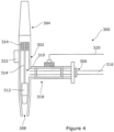
- the beer tap 300 includes a housing 302 having a tap handle 304, an inlet aperture 306 and an outlet aperture 308.
- a channel 310 is defined through housing 302 between the inlet aperture 306 and the outlet aperture 308 through which one or more items, such as for example beer, can flow in use.
- An electrical cable 320 can be connected to solenoid valve 318 to allow one or more control signals from control unit to be sent directly or indirectly to move the valve 318 between the open and closed positions.
- the solenoid valve 318 can be controlled via wireless means.
- dispensing apparatus 400 which does not form part of the present invention.
- This apparatus is capable of both wireless communication and wired communication.
- the two forms of communication can take place simultaneously to each other or independently of and/or separately of each other.
- a user can also select which form of communication is used at any particular time. This makes this embodiment of the present invention very flexible in terms of how it can be used.
- the same reference numerals have been used to describe the same features and components as mentioned in earlier embodiments.
- This WIFI transceiver unit 204 allows wireless communication with the central control unit 16 via WIFI transceiver unit 202, and also allows communication with the control unit 16 via wired connection 16.
- the provision of two possible communication pathways provides a back-up pathway in the event one of the pathways cannot work, such as if there is a loss of WIFI, if there is damage to the wired connection and/or the like.
- the single transceiver unit 204 allows control of all the solenoid valves 20 associated with all the dispensing taps 6.
- a flow meter reporting unit 402 is associated with the flow lines 8a-8c that measures the flow or liquid in each line 8a-8c.
- the flow meter reporting unit 402 is provided between the cooler 10 and the keg 4.
- the unit 402 communicates with a flow meter receiving unit 404, that in turn communicates with the control unit 400 via the transceiver unit 202 and that can signal with an information cloud to report on system controls and liquid volumes.
- the flow receiving unit 404 is the data hub control unit for receiving data from the flow meter. This sends one or more signals to the internet cloud which a customer can log on to their account and see the flow readings on liquid volumes that have passed through their system. It will also provide data relating to the temperature of the liquid, the rate of flow of the liquid and/or the like.
Landscapes
- Devices For Dispensing Beverages (AREA)
Claims (11)
- Freifluss-Getränkeausgabevorrichtung (2, 100, 200, 400) zum Ausgeben von einem oder mehr Getränkeartikeln daraus im Gebrauch; wobei die genannte Vorrichtung (2, 100, 200, 400) Folgendes beinhaltet: eine Mehrzahl von Behältern zum Fassen der ein oder der mehr auszugebenden Getränkeartikel; und eine Mehrzahl von Ausgabeauslassmitteln; wobei die Ausgabeauslassmittel konfiguriert sind, um zwischen einer geschlossenen Stellung, in der das Ausgeben der ein oder mehr Getränkeartikel daraus verhindert wird, und einer offenen Stellung, in der die ein oder mehr Getränkeartikel daraus zum Ausgeben der ein oder mehr Getränkeartikel aus der genannten Vorrichtung (2, 100, 200, 400) ausgegeben werden können, bewegt zu werden, wobei jedes der Ausgabeauslassmittel mit einem einzelnen der Behälter in Fluidverbindung steht; und eine(n) einzelne(n) Freiflusskanal oder Freiflussleitung (8a - 8c), der bzw. die zwischen jedem Behälter und den Ausgabeauslassmitteln positioniert ist, und wobei Freiflussventilmittel (mit) den genannten Ausgabeauslassmitteln versehen oder zugeordnet sind, um das Ausgeben der ein oder mehr Getränkeartikel aus den genannten Ausgabeauslassmitteln im Gebrauch zu steuern, wobei die genannten Freiflussventilmittel zwischen einer offenen Stellung, in der die ein oder mehr Getränkeartikel aus den Ausgabeauslassmitteln ausgegeben werden können, und einer geschlossenen Stellung, in der das Ausgeben der ein oder mehr Getränkeartikel aus den genannten Ausgabeauslassmitteln verhindert wird, bewegt werden können, wobei die Vorrichtung (2, 100, 200, 400) Erkennungsmittel zum Erkennen, wenn jeder der Mehrzahl von Behältern einen Mangel an den genannten auszugebenden Getränkeartikeln enthält, beinhaltet;
bei dem die Ausgabeauslassmittel elektronisch betätigte Ausgabeauslassmittel sind und die genannte Getränkeausgabevorrichtung (2, 100, 200, 400) eine Steuereinheit (16) beinhaltet, die zum Kommunizieren mit und/oder Steuern von mindestens zwei oder allen der genannten mehreren Ausgabeauslassmittel gleichzeitig und/oder jedes Ausgabeauslassmittel unabhängig von ein oder mehr anderen Ausgabeauslassmitteln direkt und über die Freiflussventilmittel (20, 318) angeordnet ist; und die Erkennungsmittel zum Kommunizieren mit der Steuereinheit (16) angeordnet sind und, bei Erkennung eines Mangels an aus dem Behälter auszugebenden Getränkeartikeln, dies der Steuereinheit (16) mitgeteilt wird, die angeordnet ist, um dem Ventilmittel zu signalisieren, sich von der offenen Stellung in die geschlossene Stellung zu bewegen. - Freifluss-Getränkeausgabevorrichtung nach Anspruch 1, wobei die Steuereinheit (16) über drahtgebundene und/oder drahtlose Mittel mit den Ausgabeauslassmitteln, den Freiflussventilmitteln und/oder den Erkennungsmitteln kommuniziert.
- Freifluss-Getränkeausgabevorrichtung nach Anspruch 2, wobei das Ausgabeauslassmittel, die Steuereinheit (16), das Freiflussventilmittel und/oder das Erkennungsmittel ein oder mehr Sendermittel, Empfängermittel und/oder Transceiver-Mittel (202, 204) zum Senden und/oder Empfangen von einem oder mehr Datensignalen im Gebrauch beinhaltet.
- Freifluss-Getränkeausgabevorrichtung nach Anspruch 1, wobei die Steuereinheit (16) fern von den Freiflussventilmitteln, den Ausgabeauslassmitteln, den Behältern und/oder den Erkennungsmitteln positioniert ist.
- Freifluss-Getränkeausgabevorrichtung nach Anspruch 1, wobei die Steuereinheit (16) ein beliebiges oder eine beliebige Kombination von Mikroprozessormitteln, Software, Speichermitteln, Benutzerbetätigungsmitteln oder Anzeigemitteln beinhaltet.
- Freifluss-Getränkeausgabevorrichtung nach Anspruch 1, wobei das Erkennungsmittel einen beliebigen Mechanismus, der die Erkennung ermöglicht, dass die Behälter leer sind und/oder einen Mangel an Getränkeartikeln zum Ausgeben aufweisen, Gewichtserkennungsmittel, Ultraschall-Erkennungsmittel, Schallpegelerkennungsmittel, Fob-Erkennungsmittel (12), einen oder mehr Reedschalter und/oder Druckerkennungsmittel beinhaltet.
- Freifluss-Getränkeausgabevorrichtung nach Anspruch 1, wobei das Freiflussventilmittel ein beliebiges oder eine beliebige Kombination aufweist von: elektronisch gesteuert, ein oder mehr Magnetventile (20, 318) beinhaltend, normalerweise in einer offenen Stellung, wenn der Behälter keinen Mangel an auszugebenden Getränkeartikeln aufweist, oder keine oder eine reduzierte Stromversorgung benötigend, um das Ventilmittel im Gebrauch in einer offenen Stellung zu halten.
- Freifluss-Getränkeausgabevorrichtung nach Anspruch 1, wobei die Stromversorgungsmittel zum Versorgen der Steuereinheit (16), der Ausgabeauslassmittel, der Freiflussventilmittel und/oder der Erkennungsmittel im Gebrauch bereitgestellt sind.
- Freifluss-Getränkeausgabevorrichtung nach Anspruch 1, wobei Anzeigemittel bereitgestellt sind, um zu ermöglichen, dass der Status der Ausgabeauslassmittel, der Freiflussventilmittel, des Freiflusskanals und/oder der Freiflussleitungen (8a - 8c) und/oder der Erkennungsmittel einem Benutzer im Gebrauch angezeigt wird.
- Freifluss-Getränkeausgabevorrichtung nach Anspruch 1, wobei ein oder mehr Heizgeräte und/oder Kühlgeräte (10) zum Erhitzen bzw. Kühlen von einem oder mehr Teilen der Vorrichtung (2, 100, 200, 400) im Gebrauch bereitgestellt sind.
- Verfahren zur Verwendung einer Freifluss-Getränkeausgabevorrichtung (2, 100, 200, 400) zum Ausgeben von einem oder mehr Getränkeartikeln daraus im Gebrauch; wobei die genannte Vorrichtung (2, 100, 200, 400) Folgendes beinhaltet: eine Mehrzahl von Behältern zum Fassen der ein oder der mehr auszugebenden Getränkeartikel; und eine Mehrzahl von Ausgabeauslassmitteln, wobei die Ausgabeauslassmittel konfiguriert sind, um zwischen einer geschlossenen Stellung, in der das Ausgeben der ein oder mehr Getränkeartikel daraus verhindert wird, und einer offenen Stellung, in der die ein oder mehr Getränkeartikel daraus zum Ausgeben der ein oder mehr Getränkeartikel aus der genannten Vorrichtung (2, 100, 200, 400) ausgegeben werden können, bewegt zu werden; wobei jedes der Ausgabeauslassmittel mit einem einzelnen der genannten Behälter in Fluidverbindung steht; und eine(n) einzelne(n) Freiflusskanal oder Freiflussleitung (8a - 8c), der bzw. die zwischen jedem der Behälter und der Ausgabeauslassmittel positioniert ist, und wobei Freiflussventilmittel (mit) den genannten Ausgabeauslassmitteln versehen oder zugeordnet sind, um das Ausgeben der ein oder mehr Getränkeartikel aus den genannten Ausgabeauslassmitteln im Gebrauch zu steuern; wobei die genannten Freiflussventilmittel zwischen einer offenen Stellung, in der die ein oder mehr Getränkeartikel aus den Ausgabeauslassmitteln ausgegeben werden können, und einer geschlossenen Stellung, in der das Ausgeben der ein oder mehr Getränkeartikel aus den genannten Ausgabeauslassmitteln verhindert wird, bewegt werden können; und die Vorrichtung (2, 100, 200, 400) Erkennungsmittel zum Erkennen, wenn die Behälter einen Mangel an den genannten auszugebenden Getränkeartikeln enthalten, beinhaltet; wobei das genannte Verfahren die folgenden Schritte beinhaltet: Ausgeben der ein oder mehr Getränkeartikel aus der Vorrichtung (2, 100, 200, 400) durch Bewegen der Freiflussventilmittel von der geschlossenen Stellung in die offene Stellung, Bewegen der Ausgabeauslassmittel von einer geschlossenen Stellung in eine offene Stellung, Bewegen der Getränkeartikel von dem Behälter zu dem Ausgabeauslassmitteln über den bzw. die mindestens eine(n) Freiflusskanal oder Freiflussleitung (8a - 8c), dadurch gekennzeichnet, dass Ausgabeauslassmittel elektronisch betätigte Ausgabeauslassmittel sind; und eine Steuereinheit (16) bereitgestellt ist, die zum Kommunizieren mit und/oder Steuern von mindestens zwei oder allen der genannten Ausgabeauslassmittel gleichzeitig und/oder jedem Ausgabeauslassmittel unabhängig von einem oder mehr anderen Ausgabeauslassmitteln direkt und über die Freiflussventilmittel (20, 318) angeordnet ist; die Erkennungsmittel mit der Steuereinheit (16) kommunizieren und bei Erkennung eines Mangels an aus dem Behälter auszugebenden Getränkeartikeln dies der Steuereinheit (16) mitgeteilt wird, die dem Freiflussventilmittel signalisiert, sich von der offenen Stellung in die geschlossene Stellung zu bewegen.
Applications Claiming Priority (1)
| Application Number | Priority Date | Filing Date | Title |
|---|---|---|---|
| GBGB1806302.4A GB201806302D0 (en) | 2018-04-18 | 2018-04-18 | Dispensing apparatus and method of use thereof |
Publications (3)
| Publication Number | Publication Date |
|---|---|
| EP3556726A1 EP3556726A1 (de) | 2019-10-23 |
| EP3556726B1 true EP3556726B1 (de) | 2025-02-26 |
| EP3556726C0 EP3556726C0 (de) | 2025-02-26 |
Family
ID=62203335
Family Applications (1)
| Application Number | Title | Priority Date | Filing Date |
|---|---|---|---|
| EP19275043.8A Active EP3556726B1 (de) | 2018-04-18 | 2019-04-03 | Freifluss-getränkeausgabevorrichtung und verfahren zur verwendung davon |
Country Status (3)
| Country | Link |
|---|---|
| US (1) | US20190322518A1 (de) |
| EP (1) | EP3556726B1 (de) |
| GB (1) | GB201806302D0 (de) |
Families Citing this family (3)
| Publication number | Priority date | Publication date | Assignee | Title |
|---|---|---|---|---|
| US11613455B1 (en) * | 2015-04-15 | 2023-03-28 | Sestra Systems, Inc. | Automated venting of gas/foam from foam on beer detector for carbonated beverages |
| CA3170145C (en) | 2020-02-07 | 2024-01-09 | Alfa Laval Copenhagen A/S | Unit for dispensing ultra-high gravity fermented beverages on draft |
| MX2022014840A (es) * | 2020-05-25 | 2023-04-04 | Sestra Systems Inc | Sistema fob para detección inteligente de flujo y control de dispensado. |
Family Cites Families (5)
| Publication number | Priority date | Publication date | Assignee | Title |
|---|---|---|---|---|
| US4305527A (en) * | 1977-06-13 | 1981-12-15 | The Cornelius Company | Method of dispensing a carbonated beverage |
| GB2165525A (en) * | 1984-08-18 | 1986-04-16 | Porter Lancastrian Ltd | Beverage dispensing apparatus with one measuring device for plural outlets |
| GB8810056D0 (en) * | 1988-04-28 | 1988-06-02 | Distillers Co Carbon Dioxide | Beverage metering system |
| GB2404651B (en) | 2003-07-02 | 2006-08-02 | Imi Cornelius | Beverage dispense |
| GB0415388D0 (en) * | 2004-07-08 | 2004-08-11 | Futuretec Technologies Ltd | Beverage quality monitoring system |
-
2018
- 2018-04-18 GB GBGB1806302.4A patent/GB201806302D0/en not_active Ceased
-
2019
- 2019-04-03 EP EP19275043.8A patent/EP3556726B1/de active Active
- 2019-04-17 US US16/386,525 patent/US20190322518A1/en not_active Abandoned
Also Published As
| Publication number | Publication date |
|---|---|
| US20190322518A1 (en) | 2019-10-24 |
| EP3556726A1 (de) | 2019-10-23 |
| GB201806302D0 (en) | 2018-05-30 |
| EP3556726C0 (de) | 2025-02-26 |
Similar Documents
| Publication | Publication Date | Title |
|---|---|---|
| US6536626B2 (en) | Self-monitoring, intelligent fountain dispenser | |
| US11845643B2 (en) | Beverage dispensing | |
| CN107531475B (zh) | 饮料分配系统 | |
| CA2628347C (en) | Automatic controller for a beverage dispensing faucet | |
| EP3556726B1 (de) | Freifluss-getränkeausgabevorrichtung und verfahren zur verwendung davon | |
| CN110831889B (zh) | 饮料分配系统 | |
| AU2001253902A1 (en) | Self-monitoring, intelligent fountain dispenser | |
| US20100170916A1 (en) | Control system for a beverage dispensing apparatus | |
| EP3053872A1 (de) | Automatisierte ausrüstung für bierausgebeanlagen | |
| WO2007053665A2 (en) | Controller-based management of a fluid dispensing system | |
| MXPA01001154A (es) | Sistema plural de suministro de liquidos. | |
| US11084705B1 (en) | Beverage dispenser with consumable monitoring system | |
| GB2505903A (en) | Dispensing beverage left in dispense lines using pressurised gas | |
| WO2024250266A1 (en) | A beverage dispensing system | |
| EP1125099A1 (de) | System und verfahren zur überwachung einer flüssigkeitsströmung | |
| IE20040152U1 (en) | An apparatus and method for cleaning beverage lines | |
| IES84068Y1 (en) | An apparatus and method for cleaning beverage lines |
Legal Events
| Date | Code | Title | Description |
|---|---|---|---|
| PUAI | Public reference made under article 153(3) epc to a published international application that has entered the european phase |
Free format text: ORIGINAL CODE: 0009012 |
|
| STAA | Information on the status of an ep patent application or granted ep patent |
Free format text: STATUS: THE APPLICATION HAS BEEN PUBLISHED |
|
| AK | Designated contracting states |
Kind code of ref document: A1 Designated state(s): AL AT BE BG CH CY CZ DE DK EE ES FI FR GB GR HR HU IE IS IT LI LT LU LV MC MK MT NL NO PL PT RO RS SE SI SK SM TR |
|
| AX | Request for extension of the european patent |
Extension state: BA ME |
|
| STAA | Information on the status of an ep patent application or granted ep patent |
Free format text: STATUS: REQUEST FOR EXAMINATION WAS MADE |
|
| 17P | Request for examination filed |
Effective date: 20200403 |
|
| STAA | Information on the status of an ep patent application or granted ep patent |
Free format text: STATUS: EXAMINATION IS IN PROGRESS |
|
| 17Q | First examination report despatched |
Effective date: 20230104 |
|
| REG | Reference to a national code |
Ref country code: DE Ref legal event code: R079 Free format text: PREVIOUS MAIN CLASS: B67D0001120000 Ipc: B67D0001080000 Ref document number: 602019066438 Country of ref document: DE |
|
| GRAP | Despatch of communication of intention to grant a patent |
Free format text: ORIGINAL CODE: EPIDOSNIGR1 |
|
| STAA | Information on the status of an ep patent application or granted ep patent |
Free format text: STATUS: GRANT OF PATENT IS INTENDED |
|
| RIC1 | Information provided on ipc code assigned before grant |
Ipc: B67D 1/08 20060101AFI20240925BHEP |
|
| INTG | Intention to grant announced |
Effective date: 20241008 |
|
| GRAS | Grant fee paid |
Free format text: ORIGINAL CODE: EPIDOSNIGR3 |
|
| GRAA | (expected) grant |
Free format text: ORIGINAL CODE: 0009210 |
|
| STAA | Information on the status of an ep patent application or granted ep patent |
Free format text: STATUS: THE PATENT HAS BEEN GRANTED |
|
| AK | Designated contracting states |
Kind code of ref document: B1 Designated state(s): AL AT BE BG CH CY CZ DE DK EE ES FI FR GB GR HR HU IE IS IT LI LT LU LV MC MK MT NL NO PL PT RO RS SE SI SK SM TR |
|
| REG | Reference to a national code |
Ref country code: GB Ref legal event code: FG4D |
|
| REG | Reference to a national code |
Ref country code: CH Ref legal event code: EP |
|
| REG | Reference to a national code |
Ref country code: DE Ref legal event code: R096 Ref document number: 602019066438 Country of ref document: DE |
|
| REG | Reference to a national code |
Ref country code: IE Ref legal event code: FG4D |
|
| U01 | Request for unitary effect filed |
Effective date: 20250317 |
|
| U07 | Unitary effect registered |
Designated state(s): AT BE BG DE DK EE FI FR IT LT LU LV MT NL PT RO SE SI Effective date: 20250324 |
|
| U20 | Renewal fee for the european patent with unitary effect paid |
Year of fee payment: 7 Effective date: 20250429 |
|
| PG25 | Lapsed in a contracting state [announced via postgrant information from national office to epo] |
Ref country code: RS Free format text: LAPSE BECAUSE OF FAILURE TO SUBMIT A TRANSLATION OF THE DESCRIPTION OR TO PAY THE FEE WITHIN THE PRESCRIBED TIME-LIMIT Effective date: 20250526 |
|
| PG25 | Lapsed in a contracting state [announced via postgrant information from national office to epo] |
Ref country code: PL Free format text: LAPSE BECAUSE OF FAILURE TO SUBMIT A TRANSLATION OF THE DESCRIPTION OR TO PAY THE FEE WITHIN THE PRESCRIBED TIME-LIMIT Effective date: 20250226 |
|
| PG25 | Lapsed in a contracting state [announced via postgrant information from national office to epo] |
Ref country code: ES Free format text: LAPSE BECAUSE OF FAILURE TO SUBMIT A TRANSLATION OF THE DESCRIPTION OR TO PAY THE FEE WITHIN THE PRESCRIBED TIME-LIMIT Effective date: 20250226 |
|
| PG25 | Lapsed in a contracting state [announced via postgrant information from national office to epo] |
Ref country code: IS Free format text: LAPSE BECAUSE OF FAILURE TO SUBMIT A TRANSLATION OF THE DESCRIPTION OR TO PAY THE FEE WITHIN THE PRESCRIBED TIME-LIMIT Effective date: 20250626 Ref country code: NO Free format text: LAPSE BECAUSE OF FAILURE TO SUBMIT A TRANSLATION OF THE DESCRIPTION OR TO PAY THE FEE WITHIN THE PRESCRIBED TIME-LIMIT Effective date: 20250526 |
|
| PG25 | Lapsed in a contracting state [announced via postgrant information from national office to epo] |
Ref country code: HR Free format text: LAPSE BECAUSE OF FAILURE TO SUBMIT A TRANSLATION OF THE DESCRIPTION OR TO PAY THE FEE WITHIN THE PRESCRIBED TIME-LIMIT Effective date: 20250226 |
|
| PG25 | Lapsed in a contracting state [announced via postgrant information from national office to epo] |
Ref country code: GR Free format text: LAPSE BECAUSE OF FAILURE TO SUBMIT A TRANSLATION OF THE DESCRIPTION OR TO PAY THE FEE WITHIN THE PRESCRIBED TIME-LIMIT Effective date: 20250527 |
|
| PGFP | Annual fee paid to national office [announced via postgrant information from national office to epo] |
Ref country code: IE Payment date: 20250429 Year of fee payment: 7 |
|
| PG25 | Lapsed in a contracting state [announced via postgrant information from national office to epo] |
Ref country code: SM Free format text: LAPSE BECAUSE OF FAILURE TO SUBMIT A TRANSLATION OF THE DESCRIPTION OR TO PAY THE FEE WITHIN THE PRESCRIBED TIME-LIMIT Effective date: 20250226 |
|
| PG25 | Lapsed in a contracting state [announced via postgrant information from national office to epo] |
Ref country code: CZ Free format text: LAPSE BECAUSE OF FAILURE TO SUBMIT A TRANSLATION OF THE DESCRIPTION OR TO PAY THE FEE WITHIN THE PRESCRIBED TIME-LIMIT Effective date: 20250226 |
|
| PG25 | Lapsed in a contracting state [announced via postgrant information from national office to epo] |
Ref country code: SK Free format text: LAPSE BECAUSE OF FAILURE TO SUBMIT A TRANSLATION OF THE DESCRIPTION OR TO PAY THE FEE WITHIN THE PRESCRIBED TIME-LIMIT Effective date: 20250226 |
|
| REG | Reference to a national code |
Ref country code: CH Ref legal event code: H13 Free format text: ST27 STATUS EVENT CODE: U-0-0-H10-H13 (AS PROVIDED BY THE NATIONAL OFFICE) Effective date: 20251125 |
|
| PG25 | Lapsed in a contracting state [announced via postgrant information from national office to epo] |
Ref country code: MC Free format text: LAPSE BECAUSE OF FAILURE TO SUBMIT A TRANSLATION OF THE DESCRIPTION OR TO PAY THE FEE WITHIN THE PRESCRIBED TIME-LIMIT Effective date: 20250226 |
|
| PLBE | No opposition filed within time limit |
Free format text: ORIGINAL CODE: 0009261 |
|
| STAA | Information on the status of an ep patent application or granted ep patent |
Free format text: STATUS: NO OPPOSITION FILED WITHIN TIME LIMIT |
|
| PG25 | Lapsed in a contracting state [announced via postgrant information from national office to epo] |
Ref country code: CH Free format text: LAPSE BECAUSE OF NON-PAYMENT OF DUE FEES Effective date: 20250430 |
|
| 26N | No opposition filed |
Effective date: 20251127 |
|
| PGFP | Annual fee paid to national office [announced via postgrant information from national office to epo] |
Ref country code: GB Payment date: 20260323 Year of fee payment: 8 |