EP3556666A1 - Radiateur déployable - Google Patents
Radiateur déployable Download PDFInfo
- Publication number
- EP3556666A1 EP3556666A1 EP17884097.1A EP17884097A EP3556666A1 EP 3556666 A1 EP3556666 A1 EP 3556666A1 EP 17884097 A EP17884097 A EP 17884097A EP 3556666 A1 EP3556666 A1 EP 3556666A1
- Authority
- EP
- European Patent Office
- Prior art keywords
- radiator
- panel
- satellite
- radiator panel
- body structure
- Prior art date
- Legal status (The legal status is an assumption and is not a legal conclusion. Google has not performed a legal analysis and makes no representation as to the accuracy of the status listed.)
- Granted
Links
- 230000007246 mechanism Effects 0.000 claims abstract description 83
- 239000012774 insulation material Substances 0.000 claims description 4
- 238000010586 diagram Methods 0.000 description 9
- 230000000052 comparative effect Effects 0.000 description 8
- 238000009413 insulation Methods 0.000 description 7
- 230000000694 effects Effects 0.000 description 5
- 238000004364 calculation method Methods 0.000 description 3
- 238000000034 method Methods 0.000 description 3
- 238000000926 separation method Methods 0.000 description 3
- 239000004918 carbon fiber reinforced polymer Substances 0.000 description 2
- 238000005516 engineering process Methods 0.000 description 2
- 238000012423 maintenance Methods 0.000 description 2
- 230000003287 optical effect Effects 0.000 description 2
- 230000000452 restraining effect Effects 0.000 description 2
- 230000007704 transition Effects 0.000 description 2
- 239000006163 transport media Substances 0.000 description 2
- 230000002159 abnormal effect Effects 0.000 description 1
- XAGFODPZIPBFFR-UHFFFAOYSA-N aluminium Chemical compound [Al] XAGFODPZIPBFFR-UHFFFAOYSA-N 0.000 description 1
- 229910052782 aluminium Inorganic materials 0.000 description 1
- 230000006872 improvement Effects 0.000 description 1
- 238000004519 manufacturing process Methods 0.000 description 1
- 238000012986 modification Methods 0.000 description 1
- 230000004048 modification Effects 0.000 description 1
- 229920001721 polyimide Polymers 0.000 description 1
- 230000009467 reduction Effects 0.000 description 1
Images


Classifications
-
- B—PERFORMING OPERATIONS; TRANSPORTING
- B64—AIRCRAFT; AVIATION; COSMONAUTICS
- B64G—COSMONAUTICS; VEHICLES OR EQUIPMENT THEREFOR
- B64G1/00—Cosmonautic vehicles
- B64G1/22—Parts of, or equipment specially adapted for fitting in or to, cosmonautic vehicles
- B64G1/46—Arrangements or adaptations of devices for control of environment or living conditions
- B64G1/50—Arrangements or adaptations of devices for control of environment or living conditions for temperature control
- B64G1/503—Radiator panels
-
- B—PERFORMING OPERATIONS; TRANSPORTING
- B23—MACHINE TOOLS; METAL-WORKING NOT OTHERWISE PROVIDED FOR
- B23P—METAL-WORKING NOT OTHERWISE PROVIDED FOR; COMBINED OPERATIONS; UNIVERSAL MACHINE TOOLS
- B23P15/00—Making specific metal objects by operations not covered by a single other subclass or a group in this subclass
- B23P15/26—Making specific metal objects by operations not covered by a single other subclass or a group in this subclass heat exchangers or the like
-
- B—PERFORMING OPERATIONS; TRANSPORTING
- B64—AIRCRAFT; AVIATION; COSMONAUTICS
- B64G—COSMONAUTICS; VEHICLES OR EQUIPMENT THEREFOR
- B64G1/00—Cosmonautic vehicles
- B64G1/22—Parts of, or equipment specially adapted for fitting in or to, cosmonautic vehicles
- B64G1/42—Arrangements or adaptations of power supply systems
- B64G1/44—Arrangements or adaptations of power supply systems using radiation, e.g. deployable solar arrays
-
- B—PERFORMING OPERATIONS; TRANSPORTING
- B64—AIRCRAFT; AVIATION; COSMONAUTICS
- B64G—COSMONAUTICS; VEHICLES OR EQUIPMENT THEREFOR
- B64G1/00—Cosmonautic vehicles
- B64G1/22—Parts of, or equipment specially adapted for fitting in or to, cosmonautic vehicles
- B64G1/46—Arrangements or adaptations of devices for control of environment or living conditions
- B64G1/50—Arrangements or adaptations of devices for control of environment or living conditions for temperature control
- B64G1/506—Heat pipes
-
- B—PERFORMING OPERATIONS; TRANSPORTING
- B64—AIRCRAFT; AVIATION; COSMONAUTICS
- B64G—COSMONAUTICS; VEHICLES OR EQUIPMENT THEREFOR
- B64G1/00—Cosmonautic vehicles
- B64G1/22—Parts of, or equipment specially adapted for fitting in or to, cosmonautic vehicles
- B64G1/52—Protection, safety or emergency devices; Survival aids
- B64G1/58—Thermal protection, e.g. heat shields
Definitions
- the present invention relates to a deployable radiator that is mounted on a satellite.
- a radiator panel is secured to the body structure surface of the satellite using a holding and releasing mechanism when the satellite is launched.
- the holding and releasing mechanism releases the radiator panel when the satellite reaches an orbit.
- the radiator panel is deployed by a deployment mechanism, thereby increasing a heat removal area.
- the radiator panel includes a condenser tube, and the body structure of the satellite includes a steam pipe. These condenser tube and steam pipe are connected by a flexible tube through which a heat transport medium passes.
- a quantity of heat generated in the body structure of the satellite is transported to the condenser tube in the radiator panel by the heat transport medium in the steam pipe through the flexible tube and is removed from the heat removal surface of the radiator panel.
- An optical solar reflector (Optical Solar Reflector) is attached to the heat removal surface of the radiator panel.
- Patent Literature 1 relates to a deployable radiator having an improved heat transport ability of a loop-type heat pipe. Patent Literature 1 also discloses a configuration in which a plurality of radiator panels are mounted on a satellite.
- Patent Literature 2 relates to a system and an apparatus for restraining spacecraft heat loss during orbit raising or between transfer orbits.
- Patent Literature 2 discloses a technology for restraining an amount of heat removal by covering a heat removal surface by a thermal shield panel during the orbit raising and increasing the amount of the heat removal by deployment on a geostationary orbit.
- Patent Literature 3 discloses a technology for stacking and stowing two radiator panels on each of west and east faces of a satellite in the satellite with four deployable radiators mounted thereon.
- radiator panel Due to an increase in an amount of heat removal caused by an increase in the size of a satellite, a necessary area for a radiator panel also increases. However, in terms of manufacturability, the radiator panel tends to be manufactured by being divided into a plurality of panels.
- each of a plurality of radiator panels is independently held by the body structure of the satellite so that the plurality of radiator panels do not stack.
- holding and releasing mechanisms just corresponding to the number of the radiator panels become necessary.
- the mass of the satellite increases.
- the radiator panels are stacked and held on each of the east and west faces.
- north and south faces of the body structure of the satellite that are heat removal surfaces are exposed to space even before the radiator panels are deployed.
- an amount of heat removal is large, so that spacecraft heat loss during orbit raising cannot be restrained.
- the north and south faces of the body structure of the satellite are used as the heat removal surfaces, and the west and east faces are not used as the heat removal surfaces.
- An object of the present invention is to provide a deployable radiator capable of reducing an increase in a mass of a satellite and improving a degree of freedom in disposition of apparatuses of the satellite. It is another object of the present invention to restrain heat loss in a spacecraft during orbit raising and improve an amount of heat removal after the spacecraft has reached a geostationary orbit.
- a deployable radiator of the present invention is a deployable radiator mounted on a body structure of a satellite.
- the deployable radiator may include:
- the first radiator panel is connected to the body structure of the satellite by the first deployment mechanism.
- the first deployment mechanism deploys the first radiator panel from the state where the first radiator panel is opposed to the north or south face of the body structure of the satellite.
- the second radiator panel is stacked with the first radiator panel to be opposed to the north or south face of the body structure of the satellite and is sandwiched between the body structure of the satellite and the first radiator panel, in the state where the first radiator panel is opposed to the north or south face of the body structure of the satellite.
- the second deployment mechanism connects the second radiator panel to the body structure of the satellite and deploys the second radiator panel in the direction opposite to the deployment direction of the first radiator panel from the state where the second radiator panel is opposed to the north or south face of the body structure of the satellite. Consequently, according to the deployable radiator of the present invention, an area of the radiator panels held on the north or south face of the body structure of the satellite can be reduced.
- an increase in a mass of the satellite can be reduced and a degree of freedom in disposition of apparatuses of the satellite can be improved. Since the deployable radiator is stowed on the north or south face of the body structure of the satellite, it becomes possible to restrain spacecraft heat loss during orbit raising and further improve an amount of heat removal after the satellite has reached a geostationary orbit.
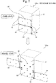
- FIG. 1 illustrates a stowed state and a deployed state of the deployable radiator 100.
- the deployable radiator 100 is mounted on a north or south face 10 of the body structure of a satellite.
- the deployable radiator 100 includes a first radiator panel 20, a first deployment mechanism 30, a second radiator panel 40, a second deployment mechanism 50, and holding and releasing mechanisms 60.
- the first radiator panel 20 is deployably connected to the north or south face 10 of the body structure of the satellite by the first deployment mechanism 30.
- the first deployment mechanism 30 connects the first radiator panel 20 to the north or south face 10 of the body structure of the satellite.
- the first deployment mechanism 30 also deploys the first radiator panel 20 from a state where the first radiator panel 20 is opposed to the north or south face 10 of the body structure of the satellite.
- a state of the first radiator panel 20 illustrated in the stowed state in FIG. 1 is the state where the first radiator panel 20 is opposed to the north or south face 10 of the body structure of the satellite.
- the second radiator panel 40 is deployably connected to the north or south face 10 of the body structure of the satellite by the second deployment mechanism 50.
- the second radiator panel 40 is stacked with the first radiator panel 20 to be opposed to the north or south face 10 of the body structure of the satellite and is sandwiched between the north or south face 10 of the body structure of the satellite and the first radiator panel 20 in the state where the first radiator panel 20 is opposed to the north or south face 10 of the body structure of the satellite. That is, in the stowed state in FIG. 1 , the second radiator panel 40 is sandwiched between the north or south face 10 of the body structure of the satellite and the first radiator panel 20 and is stacked with the first radiator panel 20.
- the second deployment mechanism 50 connects the second radiator panel 40 to the north or south face 10 of the body structure of the satellite.
- the second deployment mechanism 50 also deploys the second radiator panel 40 in a direction P2 opposite to a deployment direction P1 of the first radiator panel, from the state where the second radiator panel 40 is opposed to the north or south face 10 of the body structure of the satellite.
- Each holding and releasing mechanism 60 is constituted from a bolt to secure one of the panels, a separation nut to be engaged with the bolt, and a bracket to which those bolt and separation nut are attached, for example.
- the separation nut is a device in which an internal nut is divided by an electrical signal, thereby releasing the engagement with the bolt.
- the holding and releasing mechanisms 60 stack and hold the first radiator panel 20 and the second radiator panel 40 in the state where the first radiator panel 20 and the second radiator panel 40 are stacked with each other and are opposed to the north or south face 10 of the body structure of the satellite.
- the holding and releasing mechanisms 60 stack and hold the first radiator panel 20 and the second radiator panel 40.
- the holding and releasing mechanisms 60 also release the first radiator panel and the second radiator panel from the state where the holding and releasing mechanisms 60 have held the first radiator panel 20 and the second radiator panel 40.
- the stowed state in FIG. 1 is the state where the holding and releasing mechanisms 60 have stacked and held the first radiator panel 20 and the second radiator panel 40.
- the deployed state in FIG. 1 is the state where the holding and releasing mechanisms 60 have released the first radiator panel 20 and the second radiator panel 40.
- the second radiator panel 40 is first stowed so that the second radiator panel 40 is opposed to the north or south face 10 of the body structure of the satellite, and the first radiator panel 20 is stacked on the stowed second radiator panel 40 from an outside of the stowed second radiator panel 40 so that the first radiator panel 20 is opposed to the north or south face 10 of the body structure of the satellite. Then, two radiator panels using same holding and releasing mechanisms 60 are secured.
- the outer layer surface 22 of the first radiator panel 20 becomes an outermost layer surface that is exposed to space, in the stowed state.
- Each of the first deployment mechanism 30 and the second deployment mechanism 50 is a hinge constituted from bearings, a shaft, and brackets, for example.
- Each of the first deployment mechanism 30 and the second deployment mechanism 50 is driven by a driving source and obtains a panel deployment force.
- Each of the first deployment mechanism 30 and the second deployment mechanism 50 is driven by spring elastic energy device.
- each of the first deployment mechanism 30 and the second deployment mechanism 50 may be driven by a motor.
- each of the first deployment mechanism 30 and the second deployment mechanism 50 may be driven by a combination of a spring elastic energy device and a motor.
- FIG. 2 illustrates a deployable radiator 100x of a comparative example for being compared with the deployable radiator 100 according to this embodiment.
- each of two radiator panels is independently held on a north or south face 10 of the body structure of a satellite in a stowed state so that the two radiator panels are not stacked with each other.
- each of the radiator panels is independently secured to the north or south face 10 of the body structure of the satellite in the deployable radiator 100x of the comparative example as mentioned above, holding and releasing mechanisms 60 just corresponding to the number of the panels becomes necessary.
- 16 holding and releasing mechanisms 60 become necessary if the number of the radiator panels is two. Accordingly, a mass of the satellite increases, so that manufacturing cost also increases.
- each radiator panel is secured to the north or south face 10 of the body structure of the satellite.
- an area that is occupied by the radiator panels also doubles. Since the area of the north or south face 10 of the body structure of the satellite that is occupied by the radiator panels in the stowed state is large as mentioned above, a degree of freedom in disposition of apparatuses of the satellite is reduced. To take an example, a problem of apparatus deployment may arise that one of the radiator panels in the stowed state interferes with a solar array wing.
- the two radiator panels are stacked and held in the stowed state. Accordingly, the radiator panels can be stacked and secured to the north or south face 10 of the body structure of the satellite, using the same holding and releasing mechanisms 60. Thus, the holding and releasing mechanisms 60 corresponding to one panel are needed.
- an area of the north or south face 10 of the body structure of the satellite that is occupied by the radiator panels in the stowed state is smaller than that in the deployable radiator 100x of the comparative example.
- the area of the north or south face 10 of the body structure of the satellite that is occupied by the radiator panels is a half of that in the deployable radiator 100x of the comparative example.
- a degree of freedom in disposition of apparatuses of the satellite increases.
- the degree of freedom in the disposition of the apparatuses of the satellite increases in such a manner that the radiator panels in the stowed state and a solar array wing can be mounted side-by-side.
- the deployment mechanism for each radiator can be driven by the spring elastic energy. Consequently, according to the deployable radiator 100 in this embodiment, the deployment mechanism can be implemented without using a complex component such as the motor or a motor driving power source.
- the deployment mechanism for each radiator may be driven by the motor.
- the panels can be deployed by control of the motor so that the panels do not interfere with each other. Further, since a torque that is larger than a spring force can be generated, a large radiator panel can be accommodated. Further, according to the operation of the satellite, each radiator panel can be oriented on an orbit at an optimal angle and at an arbitrary timing.
- power consumption for temperature control of the satellite can be reduced by orienting each radiator panel on the orbit at an arbitrary timing such as a timing when the attitude of the satellite is abnormal and then returning each radiator panel to the stowed state.
- a configuration of the deployable radiator 100a according to this embodiment will be described, using FIG. 3 .
- the outer layer surface 22 of the first radiator panel 20 becomes an outermost layer surface in a stowed state. Accordingly, in order to minimize the spacecraft heat loss during the orbit raising, it is necessary to thermally insulate the outer layer surface 22 of the first radiator panel 20 that becomes the outermost layer surface. That is, it is necessary not to make heat escape from the outer layer surface 22 of the first radiator panel 20 that becomes the outermost layer surface.
- At least a portion of the outer layer surface 22 which is the opposite surface of the first opposed surface 21 that is opposed to the north or south face 10 of the body structure of the satellite is thermally insulated.
- the at least portion of the outer layer surface 22 of the first radiator panel is set to a thermally insulated surface 71.
- the thermally insulated surface 71 is generated by attaching a thermal insulation material to the outer layer surface 22.
- the thermally insulated surface 71 is generated by attaching a multi-layer insulation (Multi layer Insulation) composed of a polyimide film or the like to the outer layer surface 22.
- a multi-layer insulation Multi layer Insulation
- An amount of heat removal from the thermally insulated surface 71 to which this multi-layer insulation is attached becomes substantially zero.
- the first opposed surface 21 of the first radiator panel 20, the second opposed surface 41 of the second radiator panel 40, and the second outside surface 42 of the second radiator panel 40 are heat removal surfaces 72 from which heat is removed.
- the second outside surface 42 is also referred to as a second intermediate surface. It is necessary to remove the heats of the first opposed surface 21 of the first radiator panel 20 and both surfaces of the second radiator panel 40 in a deployed state.
- a deployable radiator includes the following features:
- the north or south face 10 of the body structure of the satellite is covered by an area corresponding to the two radiator panels, in the stowed state.
- an amount of heat removal in the stowed state can be reduced to be small. This is because the heat removal efficiency of each radiator panel is smaller than the heat removal efficiency of the body structure surface of the satellite, as mentioned above.
- each radiator panel is 1 square meter
- the amount of heat removal from the north or south face of the body structure surface of the satellite is 200 W per square meter
- the amount of heat removal from each radiator panel is 140 W per square meter.
- each radiator panel are the heat removal surfaces 72 in the deployable radiator 100 illustrated in FIG. 1 , as a second example.
- the north or south face 10 of the body structure of the satellite is overlapped by an area corresponding to one radiator panel, in the stowed state.
- an amount of heat removal in the stowed state becomes larger than that of the deployable radiator 100x of the comparative example illustrated in FIG. 2 .
- each radiator panel is 1 square meter
- the amount of heat removal from the north or south face of the body structure surface of the satellite is 200 W per square meter
- the amount of heat removal from each radiator panel is 140 W per square meter.
- the multi-layer insulation is attached to the outermost layer surface of the radiator panels on the side opposite to the north or south side 10 of the body structure of the satellite, with respect to the radiator panels stacked up at a time of the stowed state, so that an amount of heat removal becomes substantially zero.
- each radiator panel is 1 square meter
- the amount of heat removal from the north or south face of the body structure surface of the satellite is 200 W per square meter
- the amount of heat removal from each radiator panel is 140 W per square meter.
- the outermost layer surface of the radiator panels is thermally insulated.
- 820 / 200 4.1 holds, thereby indicating that the amount of the heat removal in the deployed state is 4.1 times the amount of the heat removal in the stowed state. This ratio is larger than that in the first example.
- the absolute quantity of the amount of the heat removal in the deployed state is smaller than 960 W in the first example.
- the amount of the heat removal in the stowed state is reduced to be smaller than the amount of the heat removal of 280 W in the first example.
- the deployable radiator 100a includes a thermally insulated region in at least the portion of the outer layer surface of the first radiator panel that becomes the outermost layer surface in the stowed state. Then, the other surface of the first radiator panel and the both surfaces of the second radiator panel in the deployable radiator 100a are the heat removal surfaces.
- the deployable radiator 100a is stowed on the north or south face of the body structure of the satellite.
- an amount of heat removal after the satellite has reached a geostationary orbit can be maximized while minimizing spacecraft heat loss during orbit raising, and satellite resources to be used, such as a mass of the satellite, can be minimized.
- a configuration of a deployable radiator 100b according to this embodiment will be described, using FIG. 4 .
- both surfaces of the first radiator panel 20 and both surfaces of the second radiator panel 40 are the heat removal surfaces 72.
- the first radiator panel 20 includes a thermally insulated panel 110 that covers at least a portion of the outer layer surface 22 in a state where the first radiator panel 20 is opposed to the north or south face 10 of the body structure of a satellite.
- the thermally insulated panel 110 is also referred to as a thermal shield panel, and is the one in which the surface of a sandwich plate formed of CFRP (Carbon Fiber Reinforced Plastics) and an aluminum honeycomb core is covered with a multi-layer insulation, like a solar battery panel.
- the first radiator panel 20 includes the thermally insulated panel 110 that is deployably connected to the leading end portion of the first radiator panel 20 when the first radiator panel 20 is deployed in a deployment direction P1.
- a surface opposed to the first radiator panel 20 in a stowed state, or a surface opposed to the north or south face 10 of the body structure of the satellite is set to a third opposed surface 111.
- a surface that becomes an outermost layer surface in the stowed state or the opposite surface of the third opposed surface 111 is set to a third outside surface 112.
- at least a portion of the third outside surface 112 is set to a thermally insulated surface.
- the entirety of the thermally insulated panel 110 may be formed of a thermal insulation material.
- the deployable radiator 100b includes a third deployment mechanism 120 that deployably connects the thermally insulated panel 110 to the first radiator panel 20. After the deployment of the first radiator panel 20 in the deployment direction P1 by the first deployment mechanism 30 has been started, the third deployment mechanism 120 deploys the thermally insulated panel 110 in a deployment direction P3.
- the third deployment mechanism 120 may be driven by a spring or a motor.
- the holding and releasing mechanisms 60 stacks and holds the first radiator panel 20, the second radiator panel 40, and the thermally insulated panel 110, in the stowed state.
- the rotation axis of the third deployment mechanism 120 may be rotated by 90°. That is, it may be so configured that the thermally insulated panel 110 is deployably connected at the upper end or the lower end of the first radiator panel 20 and that the thermally insulated panel 110 is deployed from the first radiator panel 20 to an upper side or a lower side of FIG. 4 .
- the deployable radiator 100b in this embodiment even if the both surfaces of the first radiator panel 20 and the both surfaces of the second radiator panel 40 have been set to the heat removal surfaces, the outermost layer surface can be thermally insulated in the stowed sate. Consequently, according to the deployable radiator 100b in this embodiment, an amount of heat removal after the satellite has reached a geostationary orbit can be further increased while minimizing spacecraft heat loss during orbit raising.
- a configuration of a deployable radiator 100c according to this embodiment will be described, using FIG. 5 .
- the deployable radiator 100c includes a deployment delay mechanism 140 to start deployment of the second radiator panel 40 after the first radiator panel 20 has been deployed by 90° or more.
- the deployment delay mechanism 140 includes a cam 142 provided at the root of the first radiator panel 20 and a roller 141 provided at the leading end of the second radiator panel 40.
- FIG. 6 is a diagram illustrating state transitions of the deployment delay mechanism 140 according to this embodiment.
- a configuration of the deployment delay mechanism 140 will be described, using FIGS. 5 and 6 .
- the deployment delay mechanism 140 includes the cam 142 at the root of the first radiator panel 20 and the roller 141 at the leading end of the second radiator panel 40. Though the roller 141 is positioned in the center of the first deployment mechanism 30 when a pair of two upper and lower radiator panels are positioned separated from each other, the rotation center of the first deployment mechanism 30 and the rotation center of the roller 141 coincide on a same straight line.
- FIG. 5 illustrates a stowed state, a first deployment state, a second deployment state, and a deployed state.
- FIG. 6 illustrates the roller 141 and the cam 142 in the stowed state, the roller 141 and the cam 142 in the first deployment state, and the roller 141 and the cam 142 in the second deployment state.
- the stowed state is the one in which the first radiator panel 20 and the second radiator panel 40 are stowed opposed to the north or south face 10 of the body structure of a satellite.
- the first deployment state is the one in which the first radiator panel 20 has been deployed up to 90° or less.
- the roller 141 Since the roller 141 is restrained by the cam 142 from the stowed state to the first deployment state, the second radiator panel 40 cannot be deployed in a deployment direction P2. Specifically, in a state where the deployment angle of the first radiator panel 20 is up to the 90° or less, the roller 141 is restrained by the cam 142. It may be so configured, for example, that the roller 141 is restrained by the cam 142 up to the deployment angle of 86°, 87°, or 89°, and the restraint of the roller 141 by the cam 142 is released at a deployment angle equal to or more than 86°, 87°, or 89°. In the following description, the description will be given, assuming that the restraint of the roller 141 by the cam 142 is released at the deployment angle of 90°.
- the first radiator panel 20 is deployed by 90° and the restraint by the cam 142 is released from the roller 141, so that the deployment of the second radiator panel 40 in the deployment direction P2 becomes possible.
- the first radiator panel 20 is deployed by 90° or more and the second radiator panel 40 is deployed in the deployment direction P2, so that the first radiator panel 20 completes the deployment.
- the deployed state is a state where each of the first radiator panel 20 and the second radiator panel 40 has completed the deployment. That is, the deployed state is a fully deployed state.
- the cam 142 restrains the roller 141.
- the second radiator panel 40 maintains a state where the second radiator panel 40 is stowed.
- the deployment of the first radiator panel 20 exceeds approximately 90°
- the restraint by the cam 142 is released, so that the roller 141 becomes free.
- the second radiator panel 40 starts the deployment. Due to this deployment delay, two radiator panels do not interfere with each other during the deployments.
- the roller may be restrained by an electromagnetic actuator instead of the cam and may be released by an electrical signal. Any other method may be adopted if the above-mentioned function of the deployment delay mechanism can be implemented.
- the deployable radiator 100c includes the deployment delay mechanism for starting the deployment of the second radiator panel after deployment of the first radiator panel by approximately 90° or more. Consequently, according to the deployable radiator 100c in this embodiment, the two radiator panels do not collide with each other during the deployments. Thus, the deployments can be performed without damaging the radiator panels. According to the deployable radiator 100c in this embodiment, a deployment failure due to interference or sticking between the radiator panels is prevented, thereby allowing improvement in deployment reliability.
- a deployable radiator 100d according to this embodiment will be described, using FIG. 7 .
- each of the two radiator panels is independently held on the north or south face 10 of the body structure of a satellite so that the two radiator panels are not stacked with each other in the stowed state. Consequently, an outer layer surface 22 of a first radiator panel 20 becomes an outermost layer surface and a second outside surface 42 of a second radiator panel 40 also becomes an outermost layer surface, in the stowed state.
- each of the outer layer surface 22 and the second outside surface 42 becomes the thermally insulated surface 71.
- the thermally insulated surface 71 is generated by attaching a thermal insulation material to each of the outer layer surface 22 and the second outside surface 42. More specifically, the thermally insulated surface 71 is generated by attaching a multi-layer insulation to each of the outer layer surface 22 and the second outside surface 42. An amount of heat removal from the thermally insulated surface 71 with this multi-layer insulation attached thereto becomes substantially zero.
- each of the outer layer surface 22 and the second outside surface 42 that become outermost layer surfaces in the stowed state are set to a thermally insulated region. Consequently, according to the deployable radiator 100d in this embodiment, spacecraft heat loss during orbit raising can be reduced.
- a deployable radiator 100e according to this embodiment will be described, using FIG. 8 .
- an outer layer surface 22 and a second outside surface 42 respectively includes thermally insulated panels 110 that are deployably connected to the leading ends of a first radiator panel 20 and a second radiator panel 40.
- These thermally insulated panels 110 are each the same as the thermally insulated panel 110 described in the third embodiment.
- each of the outer layer surface 22 and the second outside surface 42 in the deployable radiator 100e is thermally insulated by the thermally insulated panel 110.
- each of the first radiator panel 20 and the second radiator panel 40 and each thermally insulated panel 110 are connected by the third deployment mechanism 120 described in the third embodiment.
- both surfaces of the first radiator panel 20 and both surfaces of the second radiator panel 40 are the heat removal surfaces 72.
- each of the outer layer surface 22 and the second outside surface 42 that become outermost layer surfaces in the stowed state is thermally insulated by the thermally insulated panel.
- the both surfaces of the first radiator panel 20 and the both surfaces of the second radiator panel 40 are the heat removal surfaces 72. Consequently, according to the deployable radiator 100e in this embodiment, spacecraft heat loss during orbit raising can be reduced, and an amount of heat removal after the satellite has reached a geostationary orbit can be further increased.
Landscapes
- Engineering & Computer Science (AREA)
- Aviation & Aerospace Engineering (AREA)
- Remote Sensing (AREA)
- Life Sciences & Earth Sciences (AREA)
- Environmental & Geological Engineering (AREA)
- General Health & Medical Sciences (AREA)
- Toxicology (AREA)
- Environmental Sciences (AREA)
- Health & Medical Sciences (AREA)
- Biodiversity & Conservation Biology (AREA)
- Sustainable Development (AREA)
- Mechanical Engineering (AREA)
- Details Of Aerials (AREA)
- Aerials With Secondary Devices (AREA)
Applications Claiming Priority (2)
| Application Number | Priority Date | Filing Date | Title |
|---|---|---|---|
| JP2016245932 | 2016-12-19 | ||
| PCT/JP2017/009513 WO2018116490A1 (fr) | 2016-12-19 | 2017-03-09 | Radiateur déployable |
Publications (3)
| Publication Number | Publication Date |
|---|---|
| EP3556666A1 true EP3556666A1 (fr) | 2019-10-23 |
| EP3556666A4 EP3556666A4 (fr) | 2019-11-13 |
| EP3556666B1 EP3556666B1 (fr) | 2023-03-08 |
Family
ID=62626127
Family Applications (1)
| Application Number | Title | Priority Date | Filing Date |
|---|---|---|---|
| EP17884097.1A Active EP3556666B1 (fr) | 2016-12-19 | 2017-03-09 | Radiateur déployable |
Country Status (4)
| Country | Link |
|---|---|
| US (1) | US11492145B2 (fr) |
| EP (1) | EP3556666B1 (fr) |
| JP (1) | JP6698874B2 (fr) |
| WO (1) | WO2018116490A1 (fr) |
Families Citing this family (6)
| Publication number | Priority date | Publication date | Assignee | Title |
|---|---|---|---|---|
| WO2019204463A1 (fr) * | 2018-04-17 | 2019-10-24 | Raytheon Company | Structures thermiquement améliorées et déployables |
| US11760510B1 (en) * | 2020-03-09 | 2023-09-19 | Maxar Space Llc | Spacecraft design with semi-rigid solar array |
| CN113879568B (zh) * | 2021-09-06 | 2022-07-12 | 中国科学院微小卫星创新研究院 | 一种可插拔的卫星热控系统及方法 |
| US12017806B2 (en) * | 2022-01-21 | 2024-06-25 | Maxar Space Llc | Satellite with modular radiator panels |
| CN114852378B (zh) * | 2022-03-31 | 2024-05-24 | 北京空间飞行器总体设计部 | 基于单相流体回路的可展开式热辐射器 |
| CN117644996B (zh) * | 2023-12-06 | 2024-08-16 | 中国科学院微小卫星创新研究院 | 一种光学卫星 |
Family Cites Families (19)
| Publication number | Priority date | Publication date | Assignee | Title |
|---|---|---|---|---|
| JPS6361700A (ja) | 1986-09-03 | 1988-03-17 | 工業技術院長 | 展開型パネルの保持解放装置 |
| US4832113A (en) * | 1988-03-11 | 1989-05-23 | The United States Of America As Represented By The United States Department Of Energy | Survivable pulse power space radiator |
| US5732765A (en) * | 1995-12-22 | 1998-03-31 | Hughes Electronics | Adjustable heat rejection system |
| US5794890A (en) * | 1995-12-22 | 1998-08-18 | Hughes Electronics Corporation | Shielded radiator |
| US5806800A (en) * | 1995-12-22 | 1998-09-15 | Caplin; Glenn N. | Dual function deployable radiator cover |
| US6220548B1 (en) * | 1998-09-14 | 2001-04-24 | The United States Of America As Represented By The Secretary Of The Navy | Deployed equipment modules for satellite architecture improvement |
| FR2823182B1 (fr) * | 2001-04-05 | 2004-06-04 | Cit Alcatel | Radiateur deployable pour engin spatial |
| JP2003276696A (ja) | 2002-03-27 | 2003-10-02 | Mitsubishi Electric Corp | 衛星用ヒートパイプパネル |
| JP3949500B2 (ja) | 2002-04-18 | 2007-07-25 | 三菱電機株式会社 | 展開型ラジエータ及びそれを備えた人工衛星本体 |
| FR2864033B1 (fr) | 2003-12-23 | 2007-01-19 | Cit Alcatel | Dispositif de sequencement pour une structure deployable en fonction de la cinematique de l'un de ses corps mobiles |
| US7874520B2 (en) * | 2006-03-21 | 2011-01-25 | Lockheed Martin Corporation | Satellite with deployable, articulatable thermal radiators |
| JP2008265522A (ja) | 2007-04-20 | 2008-11-06 | Japan Aerospace Exploration Agency | 熱制御装置 |
| US20080289801A1 (en) * | 2007-05-02 | 2008-11-27 | Batty J Clair | Modular Thermal Management System for Spacecraft |
| EP2489593A1 (fr) * | 2011-02-21 | 2012-08-22 | European Space Agency | Satellite d'observation de la terre, système de satellite et système de lancement pour lancer les satellites |
| US8714492B2 (en) * | 2012-02-07 | 2014-05-06 | Lockheed Martin Corporation | Non-interfering deployable radiator arrangement for geo spacecraft |
| US8960608B2 (en) | 2012-02-07 | 2015-02-24 | Lockheed Martin Corporation | Deployable radiator having an increased view factor |
| EP2956364B1 (fr) | 2013-02-12 | 2020-07-15 | Lockheed Martin Corporation | Radiateur déployable à facteur de forme accru |
| US9352855B2 (en) | 2013-04-09 | 2016-05-31 | Lockheed Martin Corporation | Heat generating transfer orbit shield |
| NL2016677B1 (en) * | 2016-04-26 | 2017-11-07 | Airbus Defence And Space Netherlands B V | Solar Panel and Flexible Radiator for a Spacecraft. |
-
2017
- 2017-03-09 US US16/347,266 patent/US11492145B2/en active Active
- 2017-03-09 JP JP2018557515A patent/JP6698874B2/ja active Active
- 2017-03-09 WO PCT/JP2017/009513 patent/WO2018116490A1/fr active Application Filing
- 2017-03-09 EP EP17884097.1A patent/EP3556666B1/fr active Active
Also Published As
| Publication number | Publication date |
|---|---|
| US11492145B2 (en) | 2022-11-08 |
| EP3556666A4 (fr) | 2019-11-13 |
| EP3556666B1 (fr) | 2023-03-08 |
| US20190329912A1 (en) | 2019-10-31 |
| WO2018116490A1 (fr) | 2018-06-28 |
| JPWO2018116490A1 (ja) | 2019-03-28 |
| JP6698874B2 (ja) | 2020-05-27 |
Similar Documents
| Publication | Publication Date | Title |
|---|---|---|
| EP3556666B1 (fr) | Radiateur déployable | |
| JP4308478B2 (ja) | 展開可能な宇宙船用放熱器 | |
| EP2882649B1 (fr) | Micro-satellite de faible volume comprenant panneaux enroulés souples extensibles après lancement | |
| CN102582851B (zh) | 一种可装备卫星的可展开结构 | |
| US9242743B2 (en) | Side-by-side multiple launch configuration | |
| US10207824B2 (en) | Radiator deployable for a satellite stabilized on three axes | |
| EP3289313A1 (fr) | Système et procédé pour assembler et déployer des satellites | |
| JP2006517487A (ja) | 太陽発電パネルのヒンジ式アセンブリおよび宇宙船 | |
| US10926891B2 (en) | Hold down and release mechanism for a deployable satellite solar panel | |
| US11148834B2 (en) | Systems and methods for satellite solar panel stowage and deployment | |
| US11459128B2 (en) | Foldable tube with unitary hinge devices, systems, and methods | |
| US11670955B2 (en) | Integrated power module devices, systems, and methods | |
| US11691766B2 (en) | Deployable satellite solar panel hinge mechanism | |
| US5634612A (en) | Earth orbiting satellite having electrical energy storage batteries | |
| JP4094930B2 (ja) | 人工衛星 | |
| US11962272B2 (en) | Z-fold solar array with curved substrate panels | |
| US12040740B2 (en) | Retractable Z-fold flexible blanket solar array | |
| US11912440B2 (en) | Partially flexible solar array structure | |
| CN115416878A (zh) | 一种用于微纳卫星的帆板的展开装置 | |
| US11148831B2 (en) | Systems and methods for satellite solar panel deployment | |
| US12028016B2 (en) | Z-fold flexible blanket solar array | |
| JP2005521590A (ja) | 宇宙船、宇宙船の構築方法、及び宇宙船に使用されるアダプター | |
| Rossoni et al. | Developments in nano-satellite structural subsystem design at NASA-GSFC | |
| Takahashi et al. | MUSES-C solar array electrical and mechanical design | |
| CN116424570A (zh) | 一种一箭多星发射用的可折叠展开的堆叠卫星构型 |
Legal Events
| Date | Code | Title | Description |
|---|---|---|---|
| STAA | Information on the status of an ep patent application or granted ep patent |
Free format text: STATUS: THE INTERNATIONAL PUBLICATION HAS BEEN MADE |
|
| PUAI | Public reference made under article 153(3) epc to a published international application that has entered the european phase |
Free format text: ORIGINAL CODE: 0009012 |
|
| STAA | Information on the status of an ep patent application or granted ep patent |
Free format text: STATUS: REQUEST FOR EXAMINATION WAS MADE |
|
| 17P | Request for examination filed |
Effective date: 20190613 |
|
| AK | Designated contracting states |
Kind code of ref document: A1 Designated state(s): AL AT BE BG CH CY CZ DE DK EE ES FI FR GB GR HR HU IE IS IT LI LT LU LV MC MK MT NL NO PL PT RO RS SE SI SK SM TR |
|
| AX | Request for extension of the european patent |
Extension state: BA ME |
|
| A4 | Supplementary search report drawn up and despatched |
Effective date: 20191010 |
|
| RIC1 | Information provided on ipc code assigned before grant |
Ipc: B64G 1/50 20060101AFI20191004BHEP Ipc: B64G 1/58 20060101ALN20191004BHEP |
|
| DAV | Request for validation of the european patent (deleted) | ||
| DAX | Request for extension of the european patent (deleted) | ||
| STAA | Information on the status of an ep patent application or granted ep patent |
Free format text: STATUS: EXAMINATION IS IN PROGRESS |
|
| STAA | Information on the status of an ep patent application or granted ep patent |
Free format text: STATUS: EXAMINATION IS IN PROGRESS |
|
| 17Q | First examination report despatched |
Effective date: 20201125 |
|
| STAA | Information on the status of an ep patent application or granted ep patent |
Free format text: STATUS: EXAMINATION IS IN PROGRESS |
|
| GRAP | Despatch of communication of intention to grant a patent |
Free format text: ORIGINAL CODE: EPIDOSNIGR1 |
|
| STAA | Information on the status of an ep patent application or granted ep patent |
Free format text: STATUS: GRANT OF PATENT IS INTENDED |
|
| RIC1 | Information provided on ipc code assigned before grant |
Ipc: B64G 1/58 20060101ALN20220302BHEP Ipc: B64G 1/50 20060101AFI20220302BHEP |
|
| INTG | Intention to grant announced |
Effective date: 20220323 |
|
| GRAJ | Information related to disapproval of communication of intention to grant by the applicant or resumption of examination proceedings by the epo deleted |
Free format text: ORIGINAL CODE: EPIDOSDIGR1 |
|
| STAA | Information on the status of an ep patent application or granted ep patent |
Free format text: STATUS: EXAMINATION IS IN PROGRESS |
|
| INTC | Intention to grant announced (deleted) | ||
| GRAS | Grant fee paid |
Free format text: ORIGINAL CODE: EPIDOSNIGR3 |
|
| STAA | Information on the status of an ep patent application or granted ep patent |
Free format text: STATUS: GRANT OF PATENT IS INTENDED |
|
| RIC1 | Information provided on ipc code assigned before grant |
Ipc: B64G 1/58 20060101ALN20220809BHEP Ipc: B64G 1/50 20060101AFI20220809BHEP |
|
| GRAP | Despatch of communication of intention to grant a patent |
Free format text: ORIGINAL CODE: EPIDOSNIGR1 |
|
| RIC1 | Information provided on ipc code assigned before grant |
Ipc: B64G 1/58 20060101ALN20220816BHEP Ipc: B64G 1/50 20060101AFI20220816BHEP |
|
| INTG | Intention to grant announced |
Effective date: 20220921 |
|
| GRAA | (expected) grant |
Free format text: ORIGINAL CODE: 0009210 |
|
| STAA | Information on the status of an ep patent application or granted ep patent |
Free format text: STATUS: THE PATENT HAS BEEN GRANTED |
|
| AK | Designated contracting states |
Kind code of ref document: B1 Designated state(s): AL AT BE BG CH CY CZ DE DK EE ES FI FR GB GR HR HU IE IS IT LI LT LU LV MC MK MT NL NO PL PT RO RS SE SI SK SM TR |
|
| REG | Reference to a national code |
Ref country code: GB Ref legal event code: FG4D |
|
| REG | Reference to a national code |
Ref country code: CH Ref legal event code: EP Ref country code: AT Ref legal event code: REF Ref document number: 1552445 Country of ref document: AT Kind code of ref document: T Effective date: 20230315 |
|
| REG | Reference to a national code |
Ref country code: IE Ref legal event code: FG4D |
|
| REG | Reference to a national code |
Ref country code: DE Ref legal event code: R096 Ref document number: 602017066741 Country of ref document: DE |
|
| REG | Reference to a national code |
Ref country code: LT Ref legal event code: MG9D |
|
| REG | Reference to a national code |
Ref country code: NL Ref legal event code: MP Effective date: 20230308 |
|
| PG25 | Lapsed in a contracting state [announced via postgrant information from national office to epo] |
Ref country code: RS Free format text: LAPSE BECAUSE OF FAILURE TO SUBMIT A TRANSLATION OF THE DESCRIPTION OR TO PAY THE FEE WITHIN THE PRESCRIBED TIME-LIMIT Effective date: 20230308 Ref country code: NO Free format text: LAPSE BECAUSE OF FAILURE TO SUBMIT A TRANSLATION OF THE DESCRIPTION OR TO PAY THE FEE WITHIN THE PRESCRIBED TIME-LIMIT Effective date: 20230608 Ref country code: LV Free format text: LAPSE BECAUSE OF FAILURE TO SUBMIT A TRANSLATION OF THE DESCRIPTION OR TO PAY THE FEE WITHIN THE PRESCRIBED TIME-LIMIT Effective date: 20230308 Ref country code: LT Free format text: LAPSE BECAUSE OF FAILURE TO SUBMIT A TRANSLATION OF THE DESCRIPTION OR TO PAY THE FEE WITHIN THE PRESCRIBED TIME-LIMIT Effective date: 20230308 Ref country code: HR Free format text: LAPSE BECAUSE OF FAILURE TO SUBMIT A TRANSLATION OF THE DESCRIPTION OR TO PAY THE FEE WITHIN THE PRESCRIBED TIME-LIMIT Effective date: 20230308 Ref country code: ES Free format text: LAPSE BECAUSE OF FAILURE TO SUBMIT A TRANSLATION OF THE DESCRIPTION OR TO PAY THE FEE WITHIN THE PRESCRIBED TIME-LIMIT Effective date: 20230308 |
|
| REG | Reference to a national code |
Ref country code: AT Ref legal event code: MK05 Ref document number: 1552445 Country of ref document: AT Kind code of ref document: T Effective date: 20230308 |
|
| P01 | Opt-out of the competence of the unified patent court (upc) registered |
Effective date: 20230711 |
|
| PG25 | Lapsed in a contracting state [announced via postgrant information from national office to epo] |
Ref country code: SE Free format text: LAPSE BECAUSE OF FAILURE TO SUBMIT A TRANSLATION OF THE DESCRIPTION OR TO PAY THE FEE WITHIN THE PRESCRIBED TIME-LIMIT Effective date: 20230308 Ref country code: NL Free format text: LAPSE BECAUSE OF FAILURE TO SUBMIT A TRANSLATION OF THE DESCRIPTION OR TO PAY THE FEE WITHIN THE PRESCRIBED TIME-LIMIT Effective date: 20230308 Ref country code: GR Free format text: LAPSE BECAUSE OF FAILURE TO SUBMIT A TRANSLATION OF THE DESCRIPTION OR TO PAY THE FEE WITHIN THE PRESCRIBED TIME-LIMIT Effective date: 20230609 Ref country code: FI Free format text: LAPSE BECAUSE OF FAILURE TO SUBMIT A TRANSLATION OF THE DESCRIPTION OR TO PAY THE FEE WITHIN THE PRESCRIBED TIME-LIMIT Effective date: 20230308 |
|
| PG25 | Lapsed in a contracting state [announced via postgrant information from national office to epo] |
Ref country code: SM Free format text: LAPSE BECAUSE OF FAILURE TO SUBMIT A TRANSLATION OF THE DESCRIPTION OR TO PAY THE FEE WITHIN THE PRESCRIBED TIME-LIMIT Effective date: 20230308 Ref country code: RO Free format text: LAPSE BECAUSE OF FAILURE TO SUBMIT A TRANSLATION OF THE DESCRIPTION OR TO PAY THE FEE WITHIN THE PRESCRIBED TIME-LIMIT Effective date: 20230308 Ref country code: PT Free format text: LAPSE BECAUSE OF FAILURE TO SUBMIT A TRANSLATION OF THE DESCRIPTION OR TO PAY THE FEE WITHIN THE PRESCRIBED TIME-LIMIT Effective date: 20230710 Ref country code: EE Free format text: LAPSE BECAUSE OF FAILURE TO SUBMIT A TRANSLATION OF THE DESCRIPTION OR TO PAY THE FEE WITHIN THE PRESCRIBED TIME-LIMIT Effective date: 20230308 Ref country code: CZ Free format text: LAPSE BECAUSE OF FAILURE TO SUBMIT A TRANSLATION OF THE DESCRIPTION OR TO PAY THE FEE WITHIN THE PRESCRIBED TIME-LIMIT Effective date: 20230308 Ref country code: AT Free format text: LAPSE BECAUSE OF FAILURE TO SUBMIT A TRANSLATION OF THE DESCRIPTION OR TO PAY THE FEE WITHIN THE PRESCRIBED TIME-LIMIT Effective date: 20230308 |
|
| REG | Reference to a national code |
Ref country code: CH Ref legal event code: PL |
|
| PG25 | Lapsed in a contracting state [announced via postgrant information from national office to epo] |
Ref country code: SK Free format text: LAPSE BECAUSE OF FAILURE TO SUBMIT A TRANSLATION OF THE DESCRIPTION OR TO PAY THE FEE WITHIN THE PRESCRIBED TIME-LIMIT Effective date: 20230308 Ref country code: PL Free format text: LAPSE BECAUSE OF FAILURE TO SUBMIT A TRANSLATION OF THE DESCRIPTION OR TO PAY THE FEE WITHIN THE PRESCRIBED TIME-LIMIT Effective date: 20230308 Ref country code: IS Free format text: LAPSE BECAUSE OF FAILURE TO SUBMIT A TRANSLATION OF THE DESCRIPTION OR TO PAY THE FEE WITHIN THE PRESCRIBED TIME-LIMIT Effective date: 20230708 |
|
| REG | Reference to a national code |
Ref country code: BE Ref legal event code: MM Effective date: 20230331 |
|
| REG | Reference to a national code |
Ref country code: DE Ref legal event code: R097 Ref document number: 602017066741 Country of ref document: DE |
|
| PG25 | Lapsed in a contracting state [announced via postgrant information from national office to epo] |
Ref country code: LU Free format text: LAPSE BECAUSE OF NON-PAYMENT OF DUE FEES Effective date: 20230309 |
|
| PLBE | No opposition filed within time limit |
Free format text: ORIGINAL CODE: 0009261 |
|
| STAA | Information on the status of an ep patent application or granted ep patent |
Free format text: STATUS: NO OPPOSITION FILED WITHIN TIME LIMIT |
|
| PG25 | Lapsed in a contracting state [announced via postgrant information from national office to epo] |
Ref country code: MC Free format text: LAPSE BECAUSE OF FAILURE TO SUBMIT A TRANSLATION OF THE DESCRIPTION OR TO PAY THE FEE WITHIN THE PRESCRIBED TIME-LIMIT Effective date: 20230308 |
|
| REG | Reference to a national code |
Ref country code: IE Ref legal event code: MM4A |
|
| PG25 | Lapsed in a contracting state [announced via postgrant information from national office to epo] |
Ref country code: SI Free format text: LAPSE BECAUSE OF FAILURE TO SUBMIT A TRANSLATION OF THE DESCRIPTION OR TO PAY THE FEE WITHIN THE PRESCRIBED TIME-LIMIT Effective date: 20230308 Ref country code: MC Free format text: LAPSE BECAUSE OF FAILURE TO SUBMIT A TRANSLATION OF THE DESCRIPTION OR TO PAY THE FEE WITHIN THE PRESCRIBED TIME-LIMIT Effective date: 20230308 Ref country code: LI Free format text: LAPSE BECAUSE OF NON-PAYMENT OF DUE FEES Effective date: 20230331 Ref country code: IE Free format text: LAPSE BECAUSE OF NON-PAYMENT OF DUE FEES Effective date: 20230309 Ref country code: DK Free format text: LAPSE BECAUSE OF FAILURE TO SUBMIT A TRANSLATION OF THE DESCRIPTION OR TO PAY THE FEE WITHIN THE PRESCRIBED TIME-LIMIT Effective date: 20230308 Ref country code: CH Free format text: LAPSE BECAUSE OF NON-PAYMENT OF DUE FEES Effective date: 20230331 |
|
| 26N | No opposition filed |
Effective date: 20231211 |
|
| GBPC | Gb: european patent ceased through non-payment of renewal fee |
Effective date: 20230608 |
|
| PG25 | Lapsed in a contracting state [announced via postgrant information from national office to epo] |
Ref country code: BE Free format text: LAPSE BECAUSE OF NON-PAYMENT OF DUE FEES Effective date: 20230331 |
|
| PG25 | Lapsed in a contracting state [announced via postgrant information from national office to epo] |
Ref country code: GB Free format text: LAPSE BECAUSE OF NON-PAYMENT OF DUE FEES Effective date: 20230608 |
|
| PGFP | Annual fee paid to national office [announced via postgrant information from national office to epo] |
Ref country code: DE Payment date: 20240130 Year of fee payment: 8 |
|
| PG25 | Lapsed in a contracting state [announced via postgrant information from national office to epo] |
Ref country code: IT Free format text: LAPSE BECAUSE OF FAILURE TO SUBMIT A TRANSLATION OF THE DESCRIPTION OR TO PAY THE FEE WITHIN THE PRESCRIBED TIME-LIMIT Effective date: 20230308 |
|
| PGFP | Annual fee paid to national office [announced via postgrant information from national office to epo] |
Ref country code: FR Payment date: 20240213 Year of fee payment: 8 |