EP3556645A1 - Fahrradtretkurbelanordnung - Google Patents
Fahrradtretkurbelanordnung Download PDFInfo
- Publication number
- EP3556645A1 EP3556645A1 EP19169750.7A EP19169750A EP3556645A1 EP 3556645 A1 EP3556645 A1 EP 3556645A1 EP 19169750 A EP19169750 A EP 19169750A EP 3556645 A1 EP3556645 A1 EP 3556645A1
- Authority
- EP
- European Patent Office
- Prior art keywords
- crank
- pedal
- spindle
- cycle
- deformable member
- Prior art date
- Legal status (The legal status is an assumption and is not a legal conclusion. Google has not performed a legal analysis and makes no representation as to the accuracy of the status listed.)
- Granted
Links
Images

Classifications
-
- B—PERFORMING OPERATIONS; TRANSPORTING
- B62—LAND VEHICLES FOR TRAVELLING OTHERWISE THAN ON RAILS
- B62M—RIDER PROPULSION OF WHEELED VEHICLES OR SLEDGES; POWERED PROPULSION OF SLEDGES OR SINGLE-TRACK CYCLES; TRANSMISSIONS SPECIALLY ADAPTED FOR SUCH VEHICLES
- B62M1/00—Rider propulsion of wheeled vehicles
- B62M1/10—Rider propulsion of wheeled vehicles involving devices which enable the mechanical storing and releasing of energy occasionally, e.g. arrangement of flywheels
- B62M1/105—Rider propulsion of wheeled vehicles involving devices which enable the mechanical storing and releasing of energy occasionally, e.g. arrangement of flywheels using elastic elements
-
- B—PERFORMING OPERATIONS; TRANSPORTING
- B62—LAND VEHICLES FOR TRAVELLING OTHERWISE THAN ON RAILS
- B62M—RIDER PROPULSION OF WHEELED VEHICLES OR SLEDGES; POWERED PROPULSION OF SLEDGES OR SINGLE-TRACK CYCLES; TRANSMISSIONS SPECIALLY ADAPTED FOR SUCH VEHICLES
- B62M3/00—Construction of cranks operated by hand or foot
- B62M3/003—Combination of crank axles and bearings housed in the bottom bracket
-
- B—PERFORMING OPERATIONS; TRANSPORTING
- B62—LAND VEHICLES FOR TRAVELLING OTHERWISE THAN ON RAILS
- B62K—CYCLES; CYCLE FRAMES; CYCLE STEERING DEVICES; RIDER-OPERATED TERMINAL CONTROLS SPECIALLY ADAPTED FOR CYCLES; CYCLE AXLE SUSPENSIONS; CYCLE SIDE-CARS, FORECARS, OR THE LIKE
- B62K2201/00—Springs used in cycle frames or parts thereof
- B62K2201/06—Leaf springs
-
- B—PERFORMING OPERATIONS; TRANSPORTING
- B62—LAND VEHICLES FOR TRAVELLING OTHERWISE THAN ON RAILS
- B62M—RIDER PROPULSION OF WHEELED VEHICLES OR SLEDGES; POWERED PROPULSION OF SLEDGES OR SINGLE-TRACK CYCLES; TRANSMISSIONS SPECIALLY ADAPTED FOR SUCH VEHICLES
- B62M1/00—Rider propulsion of wheeled vehicles
- B62M1/36—Rider propulsion of wheeled vehicles with rotary cranks, e.g. with pedal cranks
-
- B—PERFORMING OPERATIONS; TRANSPORTING
- B62—LAND VEHICLES FOR TRAVELLING OTHERWISE THAN ON RAILS
- B62M—RIDER PROPULSION OF WHEELED VEHICLES OR SLEDGES; POWERED PROPULSION OF SLEDGES OR SINGLE-TRACK CYCLES; TRANSMISSIONS SPECIALLY ADAPTED FOR SUCH VEHICLES
- B62M3/00—Construction of cranks operated by hand or foot
- B62M2003/006—Crank arrangements to overcome dead points
Definitions
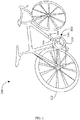
- FIG. 1 schematically shows an example bicycle 100 including a drivetrain including a crank assembly 102.
- Crank assembly 102 includes two crank arms (e.g., right crank arm 104) with pedals (e.g., right pedal 106) affixed to the ends of the crank arms.
- the two crank arms are each attached to a crank spindle 108 and mounted 180 degrees apart.
- the crank spindle may be attached to a rear wheel drivetrain connector configured to translate motion of the crank arms into motion of the rear wheel of the cycle.
- spindle 108 is attached to a chainring 110.
- Spindle 108 may be attached to chainring 110 via a cycle spider (not shown) or another suitable connector.
- Chainring 110 rotates with spindle 108, and this rotation is applied to rear wheel 112 via a bicycle chain.
- movement of the crank spindle e.g., caused by application of force to the pedals
- crank assembly 102 may be used with any suitable rear wheel drivetrain connector.
- bicycle 100 uses a bicycle spider, chainring, and bicycle chain to transfer power to real wheel 112.
- other suitable rear wheel drivetrain connectors may be used - e.g., a belt sprocket for a belt-drive bicycle, or a bevel gear for a shaft-driven bicycle.
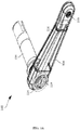
- FIG. 2 shows another view of a portion of cycle crank assembly 102.
- crank assembly 102 has been removed from bicycle 100, and pedal 106 and chainring 110 have been removed from the crank assembly.
- crank arm 104 includes a pedal interface 105 configured to accept a pedal spindle of pedal 106 shown in FIG. 1 .
- FIG. 2 more closely shows the attachment between crank arm 104 and crank spindle 108.
- crank spindle 108 will be positioned within a bottom bracket of bicycle 100 along with one or more bearings, thereby securing and stabilizing the crank spindle while allowing the crank spindle to freely rotate.
- crank arm is typically attached to a crank spindle.
- the attachment between the crank arm and the crank spindle is configured to prevent slipping of one relative to the other.
- the drivetrain is substantially rigid, such that power transfer from the crank arm to the rotating wheel is practically instantaneous and does not change along the components of the drivetrain.
- cycle crank assembly 102 incorporates a slip connection between the crank arm and crank spindle.
- the crank arm is able to rotate about the crank spindle.
- the crank arms can rotate more than the crank spindle throughout part of a pedal stroke, and the crank arms can rotate less than the crank spindle throughout another part of the pedal stroke.
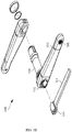
- FIGS. 3A and 3B show other partial views of cycle crank assembly 102.
- FIG. 3A shows the crank assembly in an assembled state, while FIG. 3B shows an exploded view.
- crank arm 104 is shown as being partially transparent.
- crank assembly 102 further includes a resiliently deformable member 114 and a slip connection 116, visible in FIG. 3A through the transparent crank arm and in FIG. 3B as exploded components. While FIGS. 3A and 3B only show right crank arm 104 having a resiliently deformable member and slip connection, the left crank arm may include a resiliently deformable member and slip connection as well. Because resiliently deformable member 114 is attached to crank arm 104, rotation of the crank arm causes corresponding rotation of the resiliently deformable member, which is translated to crank spindle 108.
- crank arm 104 when a load is applied to the crank arm (e.g., during a pedal downstroke), some amount of deformation of resiliently deformable member 114 will occur.
- crank arm 104 in response to the load, crank arm 104 will rotate, and resiliently deformable member 114 will deform (i.e., bend), storing a portion of the energy transferred by the load.
- the crank arm will "slip" somewhat relative to crank spindle 108, meaning the crank arm will rotate about the crank spindle.
- the crank arm may rotate by as much as one to four degrees around the spindle under load.
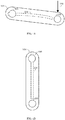
- the amount of "slip" and corresponding amount of energy storage is proportional to the force applied to the pedal. Higher forces will cause relatively more slip and relatively more energy storage. As such, the maximum amount of slip and corresponding amount of energy storage will generally occur from the pedal downstroke when the pedal is at approximately 90 degrees and pedal forces 120 are highest in the direction of rotation (as shown in FIG. 4A ). As such, the pedal downstroke may cause the crank arm 104 to rotate more than the crank spindle 108, but at least some of the difference in rotation may be stored as spring energy in the resiliently deformable member 114. This stored spring energy may be returned when relative force in the direction of rotation (i.e., pedal force 120) on the pedal decreases.
- the minimum amount of force on the pedal in the direction of rotation will generally occur during the pedal dead stroke, when the pedal is at approximately 180 degrees (As shown in FIG. 4B ).
- the resiliently deformable member 114 may return to its original shape and stored energy from the resiliently deformable member 114 may be returned.
- the released energy causes the crank spindle 108 to rotate faster than the crank arm 104, and the released energy may be transferred to the rear wheel drivetrain connector.
- the resiliently deformable member smooths the cyclist's output by storing some energy from the cyclist's most powerful portions of a pedal stroke and returning the stored energy during the cyclist's least powerful portions of the pedal stroke.
- the cycle crank assembly disclosed herein can improve the efficiency with which power is transferred to a rotating wheel by at least 4%.
- the experimental configuration included a bicycle mounted to a computerized training stand. According to the design of the training stand, the rear wheel of the bicycle was removed, and the bicycle drivetrain was attached to a disc incorporated into the training stand, such that power provided to the drivetrain of the bicycle caused rotation of the disc. Sensors attached to the disc allowed power, as well as equivalent ground speed and distance, to be measured. The power and total energy provided by the cyclist to each pedal was also measured using pedal-based power meters.
- the experiment was conducted in eight 30-minute sessions, including four sessions with a conventional crank assembly as well as four sessions with the modified crank assembly described herein.
- the average speed target as measured at the training stand, was 19.3 km/h, at a 3% slope to prevent freewheeling and coasting during the test.
- the conventional crank assembly showed an average power of 197.2W and an average total energy expenditure of 355kJ, both measured at the pedals.
- the modified crank assembly described herein the average power was 187.8W and the average total energy expenditure was 337.75kJ.
- each crank assembly had the same average speed (19.3km/h), cadence (71rpm), and equivalent distance (9.66km), when averaged across the four sessions for each crank assembly.
- the modified crank assembly described herein achieved the same average speed and equivalent ground distance despite the cyclist providing overall less power and energy to the pedals, on average. This represents an approximately 4% increase in cycling efficiency as compared to a conventional crank assembly. It is thought that the improvement can be attributed to an overall smoother torque profile, as power supplied by the cyclist during the pedal down stroke was stored by the resiliently deformable member and released during the pedal dead stroke. Energy savings may also potentially arise through reduced flexing of the bicycle frame and other components.
- resiliently deformable member 114 is shown disposed within a hollow of crank arm 104.
- the hollow will typically be larger in size than the resiliently deformable member along at least part of the length of the hollow so as to permit deformation of the resiliently deformable member while under load.
- the hollow may have any suitable size and shape.
- the hollow may narrow to have substantially the same size and shape as the resiliently deformable member proximate to pedal interface 105, such that the resiliently deformable member is snugly secured within the hollow.
- the hollow may additionally or alternatively include clips, brackets, magnets, and/or other fasteners configured to secure the resiliently deformable member in place.
- FIG. 3A shows a member holder 118 configured to secure the pedal-distal end of resiliently deformable member 114 within a hollow of crank spindle 108.
- slip connection 116 and crank spindle 108 each incorporate cutouts sized and shaped to accommodate the resiliently deformable member.
- the crank arm may have a window that aligns with the cutouts.
- the resiliently deformable member may be installed by sliding the pedal-proximate end of the resiliently-deformable member through the window, the slip connection cutout, and the crank spindle cutout until the pedal-proximate end of the resiliently deformable member is securely seated proximate to the pedal interface.
- the pedal-distal end of the resiliently-deformable member will be within the hollow of crank spindle 108, as shown in FIG. 3A .
- a protective cover or cap may optionally be installed to cover and protect the pedal-distal end of the resiliently-deformable member post-installation.
- the resiliently-deformable member may be installed and secured in any suitable way.
- the resiliently deformable member need not be positioned within the crank arm and may instead be external to the crank arm.
- the resiliently deformable member may have any suitable size and shape.
- the resiliently deformable member may be implemented as a leaf spring, with any suitable spring constant.
- the leaf spring may have a thickness of, for example, between 6 and 10 mm.
- the leaf spring may have a spring constant such that a load of 100 lbs. causes a deformation of between 0.1 and 0.5 inches, while a load of 200 lbs. causes a deformation of between 0.2 and 1.0 inches.
- the resiliently deformable member may have another suitable spring constant, structure, and/or composition.
- a preferred material for the leaf spring is fiberglass composite.
- crank arm 104 crank spindle 108, resiliently deformable member 114, etc.
- crank arm 104 crank spindle 108, resiliently deformable member 114, etc.
- metal e.g., steel or aluminum
- the components of cycle crank assembly 102 may be constructed from multiple materials, depending on what is optimal or desirable for each individual component.
- slip connection 116 permits rotation of crank arm 104 about crank spindle 108.
- Slip connection 116 may take any suitable form.
- slip connection 116 includes a sleeve bearing having two cutouts for resiliently deformable member 114 to pass through.
- Crank spindle 108 has similar cutouts, allowing resiliently deformable member 114 to pass through the hollow of the crank spindle as described above, where it is held in place by a member holder 118.
- the slip connection may take another suitable form, provided it permits rotation of the crank arm about the crank spindle.
- the shapes and arrangement of components shown in FIGS. 3A and 3B are presented as an example, and numerous changes may be made.
- Crank assembly 102 may provide numerous advantages in addition to improving pedaling efficiency.
- the maximum torque applied by the cyclist to the crank arms is reduced by the resiliently deformable members and not instantaneously transferred to the rotating wheel. This reduces the risk that the rotating wheel will slip, especially on a wet road surface.
- the resiliently deformable members may serve to absorb shocks to the cycle (e.g., when riding over a rough road surface), which can result in a smoother ride for the cyclist. Absorption of force by the resiliently deformable member can also reduce stresses and shocks to the cycle frame itself.
Landscapes
- Engineering & Computer Science (AREA)
- Mechanical Engineering (AREA)
- Chemical & Material Sciences (AREA)
- Combustion & Propulsion (AREA)
- Transportation (AREA)
- Transmission Devices (AREA)
- Organic Low-Molecular-Weight Compounds And Preparation Thereof (AREA)
Priority Applications (1)
| Application Number | Priority Date | Filing Date | Title |
|---|---|---|---|
| PL19169750T PL3556645T3 (pl) | 2018-04-17 | 2019-04-17 | <div>ZESPÓŁ KORBY ROWERU</div> |
Applications Claiming Priority (2)
| Application Number | Priority Date | Filing Date | Title |
|---|---|---|---|
| US201862659070P | 2018-04-17 | 2018-04-17 | |
| US16/367,784 US11142281B2 (en) | 2018-04-17 | 2019-03-28 | Cycle crank assembly |
Publications (2)
| Publication Number | Publication Date |
|---|---|
| EP3556645A1 true EP3556645A1 (de) | 2019-10-23 |
| EP3556645B1 EP3556645B1 (de) | 2021-12-15 |
Family
ID=66217886
Family Applications (1)
| Application Number | Title | Priority Date | Filing Date |
|---|---|---|---|
| EP19169750.7A Active EP3556645B1 (de) | 2018-04-17 | 2019-04-17 | Fahrradtretkurbelanordnung |
Country Status (8)
| Country | Link |
|---|---|
| US (1) | US11142281B2 (de) |
| EP (1) | EP3556645B1 (de) |
| JP (1) | JP7266450B2 (de) |
| CN (1) | CN110386217B (de) |
| ES (1) | ES2904801T3 (de) |
| PL (1) | PL3556645T3 (de) |
| PT (1) | PT3556645T (de) |
| TW (1) | TWI778253B (de) |
Families Citing this family (3)
| Publication number | Priority date | Publication date | Assignee | Title |
|---|---|---|---|---|
| JP2022107488A (ja) * | 2021-01-08 | 2022-07-21 | 浩一 榎田 | スプロケットとチェーンの寿命を延ばす為の自転車駆動装置と方法等 |
| US11814134B2 (en) | 2021-12-16 | 2023-11-14 | John Daniel Corder | Pivoting crank arm for increased torque |
| JP7504186B1 (ja) | 2022-12-08 | 2024-06-21 | 憲雄 籠田 | 自転車用動力伝達装置 |
Citations (5)
| Publication number | Priority date | Publication date | Assignee | Title |
|---|---|---|---|---|
| CN2513895Y (zh) * | 2001-10-11 | 2002-10-02 | 徐秉玉 | 一种可转位曲柄 |
| US20040211289A1 (en) * | 2003-04-25 | 2004-10-28 | Cheng-Hsun Chiang | Crank structure of bicycle |
| TWM286179U (en) * | 2005-07-14 | 2006-01-21 | Carbotec Ind Co Ltd | Carbon fiber bicycle crank structure with iron core |
| US20150007688A1 (en) * | 2013-07-08 | 2015-01-08 | Tien Hsin Industries Co., Ltd. | Crank arm |
| US20150175241A1 (en) * | 2013-12-20 | 2015-06-25 | Sram, Llc | Bicycle crank arm assembly |
Family Cites Families (17)
| Publication number | Priority date | Publication date | Assignee | Title |
|---|---|---|---|---|
| US4009623A (en) * | 1974-12-17 | 1977-03-01 | Interstate Sports, Inc. | Foot lever construction having controlled flexibility |
| JPS57147183U (de) * | 1981-03-10 | 1982-09-16 | ||
| EP0392063A1 (de) | 1989-04-14 | 1990-10-17 | Blättler, Arthur | Kurbel mit Totpunktüberwindung |
| US5060536A (en) | 1990-03-05 | 1991-10-29 | Boys Donald R | Flexible crank drive |
| JPH04189694A (ja) * | 1990-11-23 | 1992-07-08 | Munefusa Kobayashi | 自転車用駆動装置 |
| DE19900680A1 (de) | 1999-01-02 | 2000-07-06 | Jalmar Mathiessen | Kettenzahnrad-Kurbel-Vorrichtung zum Antreiben eines Muskelkraftfahrzeuges |
| AT410533B (de) | 2001-06-26 | 2003-05-26 | Hilber Gerhard Ing | Tretkurbelantrieb für ein fahrrad |
| JP2003072666A (ja) | 2001-06-27 | 2003-03-12 | Campagnolo Spa | 自転車用クランク、及び当該クランクの製造方法 |
| CN2533055Y (zh) | 2001-11-12 | 2003-01-29 | 徐秉玉 | 一种可转位曲柄 |
| CN2617670Y (zh) | 2003-04-14 | 2004-05-26 | 江承勋 | 改良结构的曲柄 |
| EP1792818A1 (de) * | 2005-12-02 | 2007-06-06 | Campagnolo S.R.L. | Kurbelwelle und Pedalkurbelarm eines Fahrradtretlagers, Fahrradtretkurbeleinheit mit einer solchen Kurbelwelle und einem derartigen Pedalarm und Methode zum Montieren einer Tretkurbeleinheit |
| CN101821157B (zh) | 2007-10-22 | 2012-12-19 | 浜元阳一郎 | 人力车辆用旋转传递机构及具备它的人力车辆以及自行车 |
| TWM409219U (en) * | 2010-10-14 | 2011-08-11 | Animal Bikes Inc | Bicycle pedal assembly |
| US20120304810A1 (en) | 2010-12-03 | 2012-12-06 | Christopher Butterfield | Flexible bicycle crank |
| US9403576B2 (en) | 2012-08-13 | 2016-08-02 | Willem den Boer | Power smoothing crank arm |
| US9809275B2 (en) | 2013-08-08 | 2017-11-07 | Willem den Boer | Pedal-driven vehicle crank |
| US10343745B2 (en) | 2013-09-26 | 2019-07-09 | Sram, Llc | Bicycle crank arm and chainring carrier assembly |
-
2019
- 2019-03-28 US US16/367,784 patent/US11142281B2/en active Active
- 2019-04-16 CN CN201910305009.6A patent/CN110386217B/zh active Active
- 2019-04-16 JP JP2019077785A patent/JP7266450B2/ja active Active
- 2019-04-17 PL PL19169750T patent/PL3556645T3/pl unknown
- 2019-04-17 TW TW108113366A patent/TWI778253B/zh active
- 2019-04-17 PT PT191697507T patent/PT3556645T/pt unknown
- 2019-04-17 EP EP19169750.7A patent/EP3556645B1/de active Active
- 2019-04-17 ES ES19169750T patent/ES2904801T3/es active Active
Patent Citations (5)
| Publication number | Priority date | Publication date | Assignee | Title |
|---|---|---|---|---|
| CN2513895Y (zh) * | 2001-10-11 | 2002-10-02 | 徐秉玉 | 一种可转位曲柄 |
| US20040211289A1 (en) * | 2003-04-25 | 2004-10-28 | Cheng-Hsun Chiang | Crank structure of bicycle |
| TWM286179U (en) * | 2005-07-14 | 2006-01-21 | Carbotec Ind Co Ltd | Carbon fiber bicycle crank structure with iron core |
| US20150007688A1 (en) * | 2013-07-08 | 2015-01-08 | Tien Hsin Industries Co., Ltd. | Crank arm |
| US20150175241A1 (en) * | 2013-12-20 | 2015-06-25 | Sram, Llc | Bicycle crank arm assembly |
Also Published As
| Publication number | Publication date |
|---|---|
| CN110386217B (zh) | 2022-06-10 |
| TWI778253B (zh) | 2022-09-21 |
| US11142281B2 (en) | 2021-10-12 |
| PT3556645T (pt) | 2022-01-11 |
| JP7266450B2 (ja) | 2023-04-28 |
| CN110386217A (zh) | 2019-10-29 |
| EP3556645B1 (de) | 2021-12-15 |
| PL3556645T3 (pl) | 2022-02-21 |
| US20190315430A1 (en) | 2019-10-17 |
| ES2904801T3 (es) | 2022-04-06 |
| TW201943600A (zh) | 2019-11-16 |
| JP2019182416A (ja) | 2019-10-24 |
Similar Documents
| Publication | Publication Date | Title |
|---|---|---|
| US8602434B2 (en) | Double chainring drivetrain | |
| US11142281B2 (en) | Cycle crank assembly | |
| US5860329A (en) | Pedaling mechanism for bicycles and the like | |
| US9359040B2 (en) | Electric bike retrofit for disc brakes bicycle | |
| US11548587B2 (en) | Vehicle | |
| US11993338B2 (en) | Vehicle | |
| US20030188906A1 (en) | Swing-steering system for three-wheeled vehicles | |
| US11142274B1 (en) | Recumbent bicycle and methods of riding employing supplemental upper body power, enhanced aerodynamics, stability, and control | |
| CN105764786A (zh) | 用于轻量级轮式运输车辆的电力推进的系统 | |
| CN105346668B (zh) | 无链自行车及其后轴组件 | |
| CN101848832A (zh) | 用于交通工具的驱动系统 | |
| CN206485503U (zh) | 自行车辅助动力结构 | |
| JP2019182416A5 (de) | ||
| US20080271551A1 (en) | Drive Apparatus | |
| CA3042936A1 (en) | Bicycle and bicycle frame | |
| US20140360314A1 (en) | Crankset and bottom bracket assembly | |
| US20140217695A1 (en) | Crank Assembly | |
| CN202295207U (zh) | 具差速辅助轮的自行车 | |
| Schneider | Easy rider | |
| CA2187772C (en) | Bicycle or motorcycle frame | |
| US20200385086A1 (en) | Willie's Crancks | |
| US20130181424A1 (en) | Reinforced bicycle frame | |
| KR20120010613A (ko) | 두 가지 기능을 갖는 변형자전거 | |
| CN110979540A (zh) | 一种双人自行车驱动动能传递中轴装置 | |
| CN202175147U (zh) | 折叠自行车 |
Legal Events
| Date | Code | Title | Description |
|---|---|---|---|
| PUAI | Public reference made under article 153(3) epc to a published international application that has entered the european phase |
Free format text: ORIGINAL CODE: 0009012 |
|
| STAA | Information on the status of an ep patent application or granted ep patent |
Free format text: STATUS: THE APPLICATION HAS BEEN PUBLISHED |
|
| AK | Designated contracting states |
Kind code of ref document: A1 Designated state(s): AL AT BE BG CH CY CZ DE DK EE ES FI FR GB GR HR HU IE IS IT LI LT LU LV MC MK MT NL NO PL PT RO RS SE SI SK SM TR |
|
| AX | Request for extension of the european patent |
Extension state: BA ME |
|
| STAA | Information on the status of an ep patent application or granted ep patent |
Free format text: STATUS: REQUEST FOR EXAMINATION WAS MADE |
|
| 17P | Request for examination filed |
Effective date: 20200326 |
|
| RBV | Designated contracting states (corrected) |
Designated state(s): AL AT BE BG CH CY CZ DE DK EE ES FI FR GB GR HR HU IE IS IT LI LT LU LV MC MK MT NL NO PL PT RO RS SE SI SK SM TR |
|
| STAA | Information on the status of an ep patent application or granted ep patent |
Free format text: STATUS: EXAMINATION IS IN PROGRESS |
|
| 17Q | First examination report despatched |
Effective date: 20201028 |
|
| GRAP | Despatch of communication of intention to grant a patent |
Free format text: ORIGINAL CODE: EPIDOSNIGR1 |
|
| STAA | Information on the status of an ep patent application or granted ep patent |
Free format text: STATUS: GRANT OF PATENT IS INTENDED |
|
| INTG | Intention to grant announced |
Effective date: 20210805 |
|
| GRAS | Grant fee paid |
Free format text: ORIGINAL CODE: EPIDOSNIGR3 |
|
| GRAA | (expected) grant |
Free format text: ORIGINAL CODE: 0009210 |
|
| STAA | Information on the status of an ep patent application or granted ep patent |
Free format text: STATUS: THE PATENT HAS BEEN GRANTED |
|
| AK | Designated contracting states |
Kind code of ref document: B1 Designated state(s): AL AT BE BG CH CY CZ DE DK EE ES FI FR GB GR HR HU IE IS IT LI LT LU LV MC MK MT NL NO PL PT RO RS SE SI SK SM TR |
|
| REG | Reference to a national code |
Ref country code: GB Ref legal event code: FG4D Ref country code: CH Ref legal event code: EP |
|
| REG | Reference to a national code |
Ref country code: DE Ref legal event code: R096 Ref document number: 602019010003 Country of ref document: DE |
|
| REG | Reference to a national code |
Ref country code: IE Ref legal event code: FG4D |
|
| REG | Reference to a national code |
Ref country code: PT Ref legal event code: SC4A Ref document number: 3556645 Country of ref document: PT Date of ref document: 20220111 Kind code of ref document: T Free format text: AVAILABILITY OF NATIONAL TRANSLATION Effective date: 20220105 |
|
| REG | Reference to a national code |
Ref country code: AT Ref legal event code: REF Ref document number: 1455311 Country of ref document: AT Kind code of ref document: T Effective date: 20220115 |
|
| REG | Reference to a national code |
Ref country code: NL Ref legal event code: FP |
|
| REG | Reference to a national code |
Ref country code: ES Ref legal event code: FG2A Ref document number: 2904801 Country of ref document: ES Kind code of ref document: T3 Effective date: 20220406 |
|
| REG | Reference to a national code |
Ref country code: LT Ref legal event code: MG9D |
|
| PG25 | Lapsed in a contracting state [announced via postgrant information from national office to epo] |
Ref country code: RS Free format text: LAPSE BECAUSE OF FAILURE TO SUBMIT A TRANSLATION OF THE DESCRIPTION OR TO PAY THE FEE WITHIN THE PRESCRIBED TIME-LIMIT Effective date: 20211215 Ref country code: LT Free format text: LAPSE BECAUSE OF FAILURE TO SUBMIT A TRANSLATION OF THE DESCRIPTION OR TO PAY THE FEE WITHIN THE PRESCRIBED TIME-LIMIT Effective date: 20211215 Ref country code: FI Free format text: LAPSE BECAUSE OF FAILURE TO SUBMIT A TRANSLATION OF THE DESCRIPTION OR TO PAY THE FEE WITHIN THE PRESCRIBED TIME-LIMIT Effective date: 20211215 Ref country code: BG Free format text: LAPSE BECAUSE OF FAILURE TO SUBMIT A TRANSLATION OF THE DESCRIPTION OR TO PAY THE FEE WITHIN THE PRESCRIBED TIME-LIMIT Effective date: 20220315 |
|
| REG | Reference to a national code |
Ref country code: AT Ref legal event code: MK05 Ref document number: 1455311 Country of ref document: AT Kind code of ref document: T Effective date: 20211215 |
|
| PG25 | Lapsed in a contracting state [announced via postgrant information from national office to epo] |
Ref country code: SE Free format text: LAPSE BECAUSE OF FAILURE TO SUBMIT A TRANSLATION OF THE DESCRIPTION OR TO PAY THE FEE WITHIN THE PRESCRIBED TIME-LIMIT Effective date: 20211215 Ref country code: NO Free format text: LAPSE BECAUSE OF FAILURE TO SUBMIT A TRANSLATION OF THE DESCRIPTION OR TO PAY THE FEE WITHIN THE PRESCRIBED TIME-LIMIT Effective date: 20220315 Ref country code: LV Free format text: LAPSE BECAUSE OF FAILURE TO SUBMIT A TRANSLATION OF THE DESCRIPTION OR TO PAY THE FEE WITHIN THE PRESCRIBED TIME-LIMIT Effective date: 20211215 Ref country code: HR Free format text: LAPSE BECAUSE OF FAILURE TO SUBMIT A TRANSLATION OF THE DESCRIPTION OR TO PAY THE FEE WITHIN THE PRESCRIBED TIME-LIMIT Effective date: 20211215 Ref country code: GR Free format text: LAPSE BECAUSE OF FAILURE TO SUBMIT A TRANSLATION OF THE DESCRIPTION OR TO PAY THE FEE WITHIN THE PRESCRIBED TIME-LIMIT Effective date: 20220316 |
|
| PG25 | Lapsed in a contracting state [announced via postgrant information from national office to epo] |
Ref country code: SM Free format text: LAPSE BECAUSE OF FAILURE TO SUBMIT A TRANSLATION OF THE DESCRIPTION OR TO PAY THE FEE WITHIN THE PRESCRIBED TIME-LIMIT Effective date: 20211215 Ref country code: SK Free format text: LAPSE BECAUSE OF FAILURE TO SUBMIT A TRANSLATION OF THE DESCRIPTION OR TO PAY THE FEE WITHIN THE PRESCRIBED TIME-LIMIT Effective date: 20211215 Ref country code: RO Free format text: LAPSE BECAUSE OF FAILURE TO SUBMIT A TRANSLATION OF THE DESCRIPTION OR TO PAY THE FEE WITHIN THE PRESCRIBED TIME-LIMIT Effective date: 20211215 Ref country code: EE Free format text: LAPSE BECAUSE OF FAILURE TO SUBMIT A TRANSLATION OF THE DESCRIPTION OR TO PAY THE FEE WITHIN THE PRESCRIBED TIME-LIMIT Effective date: 20211215 Ref country code: CZ Free format text: LAPSE BECAUSE OF FAILURE TO SUBMIT A TRANSLATION OF THE DESCRIPTION OR TO PAY THE FEE WITHIN THE PRESCRIBED TIME-LIMIT Effective date: 20211215 |
|
| PG25 | Lapsed in a contracting state [announced via postgrant information from national office to epo] |
Ref country code: AT Free format text: LAPSE BECAUSE OF FAILURE TO SUBMIT A TRANSLATION OF THE DESCRIPTION OR TO PAY THE FEE WITHIN THE PRESCRIBED TIME-LIMIT Effective date: 20211215 |
|
| REG | Reference to a national code |
Ref country code: DE Ref legal event code: R097 Ref document number: 602019010003 Country of ref document: DE |
|
| PG25 | Lapsed in a contracting state [announced via postgrant information from national office to epo] |
Ref country code: IS Free format text: LAPSE BECAUSE OF FAILURE TO SUBMIT A TRANSLATION OF THE DESCRIPTION OR TO PAY THE FEE WITHIN THE PRESCRIBED TIME-LIMIT Effective date: 20220415 |
|
| PLBE | No opposition filed within time limit |
Free format text: ORIGINAL CODE: 0009261 |
|
| STAA | Information on the status of an ep patent application or granted ep patent |
Free format text: STATUS: NO OPPOSITION FILED WITHIN TIME LIMIT |
|
| PG25 | Lapsed in a contracting state [announced via postgrant information from national office to epo] |
Ref country code: DK Free format text: LAPSE BECAUSE OF FAILURE TO SUBMIT A TRANSLATION OF THE DESCRIPTION OR TO PAY THE FEE WITHIN THE PRESCRIBED TIME-LIMIT Effective date: 20211215 Ref country code: AL Free format text: LAPSE BECAUSE OF FAILURE TO SUBMIT A TRANSLATION OF THE DESCRIPTION OR TO PAY THE FEE WITHIN THE PRESCRIBED TIME-LIMIT Effective date: 20211215 |
|
| 26N | No opposition filed |
Effective date: 20220916 |
|
| PG25 | Lapsed in a contracting state [announced via postgrant information from national office to epo] |
Ref country code: SI Free format text: LAPSE BECAUSE OF FAILURE TO SUBMIT A TRANSLATION OF THE DESCRIPTION OR TO PAY THE FEE WITHIN THE PRESCRIBED TIME-LIMIT Effective date: 20211215 |
|
| REG | Reference to a national code |
Ref country code: CH Ref legal event code: PL |
|
| PG25 | Lapsed in a contracting state [announced via postgrant information from national office to epo] |
Ref country code: MC Free format text: LAPSE BECAUSE OF FAILURE TO SUBMIT A TRANSLATION OF THE DESCRIPTION OR TO PAY THE FEE WITHIN THE PRESCRIBED TIME-LIMIT Effective date: 20211215 Ref country code: LU Free format text: LAPSE BECAUSE OF NON-PAYMENT OF DUE FEES Effective date: 20220417 Ref country code: LI Free format text: LAPSE BECAUSE OF NON-PAYMENT OF DUE FEES Effective date: 20220430 Ref country code: CH Free format text: LAPSE BECAUSE OF NON-PAYMENT OF DUE FEES Effective date: 20220430 |
|
| PG25 | Lapsed in a contracting state [announced via postgrant information from national office to epo] |
Ref country code: IE Free format text: LAPSE BECAUSE OF NON-PAYMENT OF DUE FEES Effective date: 20220417 |
|
| PGFP | Annual fee paid to national office [announced via postgrant information from national office to epo] |
Ref country code: PL Payment date: 20230406 Year of fee payment: 5 |
|
| PG25 | Lapsed in a contracting state [announced via postgrant information from national office to epo] |
Ref country code: HU Free format text: LAPSE BECAUSE OF FAILURE TO SUBMIT A TRANSLATION OF THE DESCRIPTION OR TO PAY THE FEE WITHIN THE PRESCRIBED TIME-LIMIT; INVALID AB INITIO Effective date: 20190417 |
|
| PG25 | Lapsed in a contracting state [announced via postgrant information from national office to epo] |
Ref country code: MK Free format text: LAPSE BECAUSE OF FAILURE TO SUBMIT A TRANSLATION OF THE DESCRIPTION OR TO PAY THE FEE WITHIN THE PRESCRIBED TIME-LIMIT Effective date: 20211215 Ref country code: CY Free format text: LAPSE BECAUSE OF FAILURE TO SUBMIT A TRANSLATION OF THE DESCRIPTION OR TO PAY THE FEE WITHIN THE PRESCRIBED TIME-LIMIT Effective date: 20211215 |
|
| PG25 | Lapsed in a contracting state [announced via postgrant information from national office to epo] |
Ref country code: TR Free format text: LAPSE BECAUSE OF FAILURE TO SUBMIT A TRANSLATION OF THE DESCRIPTION OR TO PAY THE FEE WITHIN THE PRESCRIBED TIME-LIMIT Effective date: 20211215 |
|
| PG25 | Lapsed in a contracting state [announced via postgrant information from national office to epo] |
Ref country code: MT Free format text: LAPSE BECAUSE OF FAILURE TO SUBMIT A TRANSLATION OF THE DESCRIPTION OR TO PAY THE FEE WITHIN THE PRESCRIBED TIME-LIMIT Effective date: 20211215 |
|
| PGFP | Annual fee paid to national office [announced via postgrant information from national office to epo] |
Ref country code: NL Payment date: 20250422 Year of fee payment: 7 |
|
| PGFP | Annual fee paid to national office [announced via postgrant information from national office to epo] |
Ref country code: DE Payment date: 20250424 Year of fee payment: 7 |
|
| PGFP | Annual fee paid to national office [announced via postgrant information from national office to epo] |
Ref country code: ES Payment date: 20250519 Year of fee payment: 7 Ref country code: GB Payment date: 20250423 Year of fee payment: 7 |
|
| PGFP | Annual fee paid to national office [announced via postgrant information from national office to epo] |
Ref country code: IT Payment date: 20250430 Year of fee payment: 7 Ref country code: BE Payment date: 20250422 Year of fee payment: 7 |
|
| PGFP | Annual fee paid to national office [announced via postgrant information from national office to epo] |
Ref country code: PT Payment date: 20250409 Year of fee payment: 7 |
|
| PGFP | Annual fee paid to national office [announced via postgrant information from national office to epo] |
Ref country code: FR Payment date: 20250428 Year of fee payment: 7 |
|
| PG25 | Lapsed in a contracting state [announced via postgrant information from national office to epo] |
Ref country code: PL Free format text: LAPSE BECAUSE OF FAILURE TO SUBMIT A TRANSLATION OF THE DESCRIPTION OR TO PAY THE FEE WITHIN THE PRESCRIBED TIME-LIMIT Effective date: 20240417 |
|
| PG25 | Lapsed in a contracting state [announced via postgrant information from national office to epo] |
Ref country code: PL Free format text: LAPSE BECAUSE OF NON-PAYMENT OF DUE FEES Effective date: 20240417 |