EP3556623A1 - Snap-in oriented fitting - Google Patents
Snap-in oriented fitting Download PDFInfo
- Publication number
- EP3556623A1 EP3556623A1 EP18214516.9A EP18214516A EP3556623A1 EP 3556623 A1 EP3556623 A1 EP 3556623A1 EP 18214516 A EP18214516 A EP 18214516A EP 3556623 A1 EP3556623 A1 EP 3556623A1
- Authority
- EP
- European Patent Office
- Prior art keywords
- plug portion
- orientation plate
- tube
- connector system
- plug
- Prior art date
- Legal status (The legal status is an assumption and is not a legal conclusion. Google has not performed a legal analysis and makes no representation as to the accuracy of the status listed.)
- Withdrawn
Links
- 230000014759 maintenance of location Effects 0.000 claims abstract description 28
- 238000007789 sealing Methods 0.000 claims abstract description 17
- 239000011324 bead Substances 0.000 claims description 9
- 239000002184 metal Substances 0.000 claims description 5
- 229920003023 plastic Polymers 0.000 claims description 5
- 239000004033 plastic Substances 0.000 claims description 5
- 238000003780 insertion Methods 0.000 description 5
- 230000037431 insertion Effects 0.000 description 5
- 238000000034 method Methods 0.000 description 5
- 239000012530 fluid Substances 0.000 description 4
- 239000000463 material Substances 0.000 description 3
- 230000006835 compression Effects 0.000 description 2
- 238000007906 compression Methods 0.000 description 2
- 238000005096 rolling process Methods 0.000 description 2
- 241001272567 Hominoidea Species 0.000 description 1
- 238000010276 construction Methods 0.000 description 1
- 230000001419 dependent effect Effects 0.000 description 1
- 238000002347 injection Methods 0.000 description 1
- 239000007924 injection Substances 0.000 description 1
- 238000009434 installation Methods 0.000 description 1
- 230000013011 mating Effects 0.000 description 1
Images


Classifications
-
- F—MECHANICAL ENGINEERING; LIGHTING; HEATING; WEAPONS; BLASTING
- F16—ENGINEERING ELEMENTS AND UNITS; GENERAL MEASURES FOR PRODUCING AND MAINTAINING EFFECTIVE FUNCTIONING OF MACHINES OR INSTALLATIONS; THERMAL INSULATION IN GENERAL
- F16L—PIPES; JOINTS OR FITTINGS FOR PIPES; SUPPORTS FOR PIPES, CABLES OR PROTECTIVE TUBING; MEANS FOR THERMAL INSULATION IN GENERAL
- F16L37/00—Couplings of the quick-acting type
- F16L37/008—Couplings of the quick-acting type for branching pipes; for joining pipes to walls
-
- F—MECHANICAL ENGINEERING; LIGHTING; HEATING; WEAPONS; BLASTING
- F16—ENGINEERING ELEMENTS AND UNITS; GENERAL MEASURES FOR PRODUCING AND MAINTAINING EFFECTIVE FUNCTIONING OF MACHINES OR INSTALLATIONS; THERMAL INSULATION IN GENERAL
- F16L—PIPES; JOINTS OR FITTINGS FOR PIPES; SUPPORTS FOR PIPES, CABLES OR PROTECTIVE TUBING; MEANS FOR THERMAL INSULATION IN GENERAL
- F16L41/00—Branching pipes; Joining pipes to walls
-
- B—PERFORMING OPERATIONS; TRANSPORTING
- B60—VEHICLES IN GENERAL
- B60T—VEHICLE BRAKE CONTROL SYSTEMS OR PARTS THEREOF; BRAKE CONTROL SYSTEMS OR PARTS THEREOF, IN GENERAL; ARRANGEMENT OF BRAKING ELEMENTS ON VEHICLES IN GENERAL; PORTABLE DEVICES FOR PREVENTING UNWANTED MOVEMENT OF VEHICLES; VEHICLE MODIFICATIONS TO FACILITATE COOLING OF BRAKES
- B60T17/00—Component parts, details, or accessories of power brake systems not covered by groups B60T8/00, B60T13/00 or B60T15/00, or presenting other characteristic features
- B60T17/04—Arrangements of piping, valves in the piping, e.g. cut-off valves, couplings or air hoses
- B60T17/043—Brake line couplings, air hoses and stopcocks
Definitions
- tubing connections can require many tubing connections to be made to carry fluids throughout the various parts of the engine.
- tubing connections utilize a threaded fitting and nut connection to provide a compression seal.
- the compression seal can also prevent the tubing from rotating.
- threaded fittings can take a substantial amount of time, because each connection needs to be individually threaded.
- the threads are liable to be damaged or stripped if the nut is initially misaligned or if the nut is overtightened. Accordingly, alternative systems for making tubing connections more quickly would be desirable.
- Some embodiments include a connector system.
- the connector system includes a plug portion and a receiving portion.
- the plug portion includes a resilient retention portion at the forward end of the plug portion, a sealing member distal from the retention portion, an orientation plate rigidly connected to the plug portion.
- the receiving portion includes a hole through the receiving portion, wherein the hole has a diameter smaller than a largest diameter of the resilient retention portion, a shoulder on one side of the receiving portion that cooperates with the retention portion to fix the axial position of the plug portion in the receiving portion, a recess on the opposite side of the receiving portion, wherein the orientation plate fits within the recess to fix the rotational orientation of the plug portion with respect to the receiving portion.
- the retention portion comprises a forward-facing ramp and a rear-facing ramp.
- the forward-facing ramp has a smaller angle of inclination as compared to the rear-facing ramp.
- the retention portion comprises a forward-facing ramp and a rear-facing ramp, and the retention portion is divided into a plurality of axially-extending fingers around a circumference of the plug portion.
- the plug portion comprises an O-ring as the sealing member, and the O-ring is juxtaposed next to the orientation plate.
- the plug portion comprises a tube, wherein the retention portion is formed from the tube, and the orientation plate is attached stationarily with respect to the tube.
- the frontal profile of the orientation plate is a polygon.
- the polygon has from 3 to 64 sides.
- the frontal profile of the orientation plate has one or more curved surfaces.
- the frontal profile of the orientation plate has a repeating shape.
- the receiving portion has a second diameter larger than the hole, wherein the second diameter forms a frontal face and a radial face, and the sealing member contacts at least the radial face.
- the receiving portion has a notch extending into the recess.
- the plug portion is made from a metal or from a plastic.
- a bead is juxtaposed next to the sealing member.
- the orientation plate has a frontal profile in the shape of a hexagon.
- the sealing member is press fit into a second diameter on the receiving portion, wherein the second diameter is larger than the hole diameter.
- a port for purposes of this application can be any opening for any fluid, for example, ports and tubing may be used to carry brake fluid throughout the braking system.
- the connector system relies on two portions designed to work with each other to make a fluid-tight connection that also provides a fixed orientation so as to prevent rotation.
- the connector system includes a plug portion on the end of tubing for example, and a mating receiving portion at the port to which the tubing is to be attached.
- front "forward,” and derivatives thereof are used to denote a direction toward the left side with respect to the figures.
- rear “backwards,” and derivatives thereof are used to denote a direction toward the right side with respect to the figures.
- the plug portion 101 of the connector system is illustrated.
- the plug portion 101 may be constructed from the end of the tubing 102, or, alternatively, the plug portion 101 can be fabricated separately from the tubing 102 and thereafter attached to or otherwise affixed to the end of tubing 102.
- the plug portion 101 includes a straight tube or tubing 102.
- the tubing 102 can be made of metal or plastics, for example.
- the tubing 102 is of suitable inner diameter size and wall thickness for the intended application of pressure and temperature and the material of construction is selected to be compatible with the fluid being carried by the tubing 102.
- the forward end of the plug portion 101 includes a retention portion 103 having a larger outer diameter than the outer diameter of the tubing 102.
- the retention portion 103 includes a forward-facing ramp 106 and a rear-facing ramp 108.
- the forward-facing ramp 106 and the rear-facing ramp converge at the apes.
- the forward ramp 106 and the rear ramp 108 can be rolled onto the end of metal tubing using a bead rolling process, for example.
- the tubing 102 can then be cut radially into a plurality of fingers 104.
- Each finger 104 includes a forward-facing ramp and a rear-facing ramp.
- the forward ramp 106 is at an angle less than 90° (degrees) with respect to the longitudinal axis of the tubing 102.
- the rear ramp 108 can be at an angle less than 90° with respect to the longitudinal axis of the tubing 102. The angle of the forward ramp 106 and the rear ramp 108 can be adjusted so as to fine tune the required force to make either the insertion process or the removal process easier or difficult.
- the forward ramp 106 can be set at a much smaller inclination angle in comparison to the rear ramp 108 so as to make insertion of the plug portion 101 much easier than the removal operation.
- the rear ramp 108 can be at an angle of 90°.
- the plug portion 101 and all its features can be injection molded, for example.
- the plug portion 101 includes a bead 110 formed form the tubing 102.
- the bead 110 is to the rear of the retention portion 102.
- the bead 110 holds an O-ring 112 from moving forward on the tubing 102.
- the bead 110 can be an optional feature.
- the O-ring 112 is used to seal an interface between the plug portion 101 and surface on the port.
- the O-ring 112 has an outer diameter that is larger than the outer diameter of the tubing 112 and the bead 110.
- An orientation plate 114 is placed on the rear side of the O-ring 112, and retains the O-ring from moving backwards on the tubing 102.
- the orientation plate 114 can be crimped, brazed, welded, or pressed onto the tube 102 so that it positively holds the orientation of the tube 102.
- the orientation plate 114 may formed from the tube 102 material via a rolling, forming, or hydroforming process.
- the orientation plate 114 is rigidly or stationarily held to the tubing 102 so that there is no rotation allowed between the orientation plate 114 with respect to the tube 102, nor is there longitudinal sliding of the orientation plate 114 with respect to the tube 102.
- the orientation plate 114 outer dimension is larger than the outer dimension of the O-ring 112.
- the frontal profile (as illustrated in FIGURE 2 ) of the orientation plate 114 is any non-circular shape, preferably with a repeating pattern so the entire fitting can be caught into a fixed orientation.
- a frontal profile as used herein is the outline of a front (or rear) surface as seen on a vertical cross section oriented normal to the front (or rear) surface.
- the orientation plate 114 can have one or more flat sides, or alternatively one or more curved sides or shapes, or a combination of flat sides and curved shapes.
- the orientation plate 114 may also include internal features, such as that the orientation plate 114 can have a number of holes.
- the orientation plate 114 can have a repeating structure so that the tubing 102 can be selected to have a rotational orientation. That is, the tubing 102 can be fixed at a rotational angle with respect to the receiving portion at angles dictated by the orientation plate 114.
- an eight-sided orientation plate 114 as illustrated in FIGURE 2 , allows orienting the tubing 102 into one of eight positions, each position differing from the next by 45 degrees of rotation. While a representative embodiment of an orientation plate is illustrated, it is to be understood that the orientation plate 114 is not limited to one having 8 equal sides, the orientation plate can be, for example, a polygon having from 3 to 64, or even more, straight edges. Alternatively, the orientation plate 114 can have other shapes, including curved shapes such as lobes. The orientation plate 114 can be a combination of straight edges with curved sections, as well.
- the receiving portion 116 has a hole 117 made of a first diameter smaller than the largest diameter at the apex wherein the ramps 106 and 108 converge, but at least larger than the tube 102 outer diameter.
- the hole 117 is however longitudinally shorter than the tubing 102 section between the orientation plate 114 and the rear-facing ramp 108 so as to allow the rear-facing ramp 108 to engage a shoulder 124 at the forward end of the hole 117.
- the receiving portion 116 includes a second diameter 120 made larger than the diameter of the hole 117 to allow the O-ring 112 to fit therein.
- the second diameter 120 is collinear with respect to the hole 117.
- the step in size between the first diameter and the second diameter 120 creates a frontal wall 121.
- the second diameter 120 can be slightly smaller than the outer diameter of the O-ring 112 such that the O-ring 112 creates a fluid-tight seal in the radial direction against the second diameter wall 120.
- the receiving portion 116 includes a recessed portion 118 that is provided at the entrance to the hole 117.
- the recessed portion 118 is the negative shape of the orientation plate 114, and the recess 118 has a frontal profile that closely matches the frontal profile of the orientation plate 114.
- the receiving portion 116 can have the positive or the negative shape to mate with the orientation plate 114.
- the orientation plate 114 is made to be a close tolerance fit within the recessed portion 118.
- the forward-facing ramps 104 on the fingers 104 contact the hole 117 such that the individual fingers 104 will deflect radially inward to allow passage of the plug 101 through the hole 117.
- the fingers 114 will spring resiliently radially outward so that the rear-facing ramp 108 will contact the edge of the opposite end of the hole 117 at the ramp 124.
- the rear ramps 108 may apply an axial force forcing the tubing 102 forward.
- the orientation plate 114 may on the frontal face of the recess 118.
- the O-ring 112 can be appropriately toleranced diametrically (radially) so that the O-ring 114 can seal against the outside wall of the tube 102 and the second diameter wall 120 in the radial direction.
- the interference or press fit of the O-ring into the second diameter 120 should be sufficient to create a seal.
- the diameter 120 can be slightly smaller than the outer diameter of the O-ring 112, such that the O-ring 112 will need to compress slightly to be inserted into the diameter 102.
- the O-ring 112 can create an outward radial force against the diameter 120 so as to create a sealing surface.
- the radial force also compresses the inner diameter of the O-ring 112 against the outer diameter of the tube 102 so as to create a sealing surface at this location as well.
- the recessed portion 118 will receive the orientation plate 114.
- the orientation plate 114 will be inserted into the recess 118 to prevent rotation after insertion.
- the orientation plate 114 placement into the recess 118 is neither an interference fit nor press fit, but there is simply a close fit tolerance to allow placement, and, once placed in the recess 114, the orientation plate 114 resists rotation. Because the orientation plate 114 is provided with a repeating pattern at the outer perimeter, the orientation plate 114 can be angularly oriented in a plurality of present angles. The number of orientations is dictated by the number of straight edges making up the perimeter, for example.
- the insertion force of the plug portion 101 will be lower than the removal force.
- Some embodiments include a connector system.
- the connector system includes a plug portion and a receiving portion.
- the plug portion includes a resilient retention portion at the forward end of the plug portion, a sealing member distal from the retention portion, an orientation plate rigidly connected to the plug portion.
- the receiving portion includes a hole through the receiving portion, wherein the hole has a diameter smaller than a largest diameter of the resilient retention portion, a shoulder on one side of the receiving portion that cooperates with the retention portion to fix the axial position of the plug portion in the receiving portion, a recess on the opposite side of the receiving portion, wherein the orientation plate fits within the recess to fix the rotational orientation of the plug portion with respect to the receiving portion.
- the retention portion comprises a forward-facing ramp and a rear-facing ramp.
- the forward-facing ramp has a smaller angle of inclination as compared to the rear-facing ramp.
- the retention portion comprises a forward-facing ramp and a rear-facing ramp, and the retention portion is divided into a plurality of axially-extending fingers around a circumference of the plug portion.
- the plug portion comprises an O-ring as the sealing member, and the O-ring is juxtaposed next to the orientation plate.
- the plug portion comprises a tube, wherein the retention portion is formed from the tube, and the orientation plate is attached stationarily with respect to the tube.
- the frontal profile of the orientation plate is a polygon.
- the polygon has from 3 to 64 sides.
- the frontal profile of the orientation plate has one or more curved surfaces.
- the frontal profile of the orientation plate has a repeating shape.
- the receiving portion has a second diameter larger than the hole, wherein the second diameter forms a frontal face and a radial face, and the sealing member contacts at least the radial face.
- the receiving portion has a notch extending into the recess.
- the plug portion is made from a metal or from a plastic.
- a bead is juxtaposed next to the sealing member.
- the orientation plate has a frontal profile in the shape of a hexagon.
- the sealing member is press fit into a second diameter on the receiving portion, wherein the second diameter is larger than the hole diameter.
Abstract
Description
- Complex machinery such as a truck engine can require many tubing connections to be made to carry fluids throughout the various parts of the engine. Conventionally, tubing connections utilize a threaded fitting and nut connection to provide a compression seal. The compression seal can also prevent the tubing from rotating. The use of threaded fittings, however, can take a substantial amount of time, because each connection needs to be individually threaded. Furthermore, the threads are liable to be damaged or stripped if the nut is initially misaligned or if the nut is overtightened. Accordingly, alternative systems for making tubing connections more quickly would be desirable.
- Some embodiments include a connector system. The connector system includes a plug portion and a receiving portion. The plug portion includes a resilient retention portion at the forward end of the plug portion, a sealing member distal from the retention portion, an orientation plate rigidly connected to the plug portion. The receiving portion includes a hole through the receiving portion, wherein the hole has a diameter smaller than a largest diameter of the resilient retention portion, a shoulder on one side of the receiving portion that cooperates with the retention portion to fix the axial position of the plug portion in the receiving portion, a recess on the opposite side of the receiving portion, wherein the orientation plate fits within the recess to fix the rotational orientation of the plug portion with respect to the receiving portion.
- In some embodiments of the connector system, the retention portion comprises a forward-facing ramp and a rear-facing ramp.
- In some embodiments of the connector system, the forward-facing ramp has a smaller angle of inclination as compared to the rear-facing ramp.
- In some embodiments of the connector system, the retention portion comprises a forward-facing ramp and a rear-facing ramp, and the retention portion is divided into a plurality of axially-extending fingers around a circumference of the plug portion.
- In some embodiments of the connector system, the plug portion comprises an O-ring as the sealing member, and the O-ring is juxtaposed next to the orientation plate.
- In some embodiments of the connector system, the plug portion comprises a tube, wherein the retention portion is formed from the tube, and the orientation plate is attached stationarily with respect to the tube.
- In some embodiments of the connector system, the frontal profile of the orientation plate is a polygon.
- In some embodiments of the connector system, the polygon has from 3 to 64 sides.
- In some embodiments of the connector system, the frontal profile of the orientation plate has one or more curved surfaces.
- In some embodiments of the connector system, the frontal profile of the orientation plate has a repeating shape.
- In some embodiments of the connector system, the receiving portion has a second diameter larger than the hole, wherein the second diameter forms a frontal face and a radial face, and the sealing member contacts at least the radial face.
- In some embodiments of the connector system, the receiving portion has a notch extending into the recess.
- In some embodiments of the connector system, the plug portion is made from a metal or from a plastic.
- In some embodiments of the connector system, a bead is juxtaposed next to the sealing member.
- In some embodiments of the connector system, the orientation plate has a frontal profile in the shape of a hexagon.
- In some embodiments of the connector system, the sealing member is press fit into a second diameter on the receiving portion, wherein the second diameter is larger than the hole diameter.
- The foregoing aspects and many of the attendant advantages of this invention will become more readily appreciated as the same become better understood by reference to the following detailed description, when taken in conjunction with the accompanying drawings, wherein:
-
FIGURE 1 is a diagrammatical illustration of a plug in a connector system; -
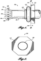
FIGURE 2 is a diagrammatical illustration of the plug ofFIGURE 1 showing a multi-sided orientation plate; -
FIGURE 3 is a diagrammatical cross sectional illustration of the plug portion and receiving portion of the connector system; and -
FIGURE 4 is a diagrammatical illustration of the connector system ofFIGURE 3 showing a multi-sided orientation plate. - Described herein is a connector system for attaching tubing, for example, to a port. A port for purposes of this application can be any opening for any fluid, for example, ports and tubing may be used to carry brake fluid throughout the braking system. The connector system relies on two portions designed to work with each other to make a fluid-tight connection that also provides a fixed orientation so as to prevent rotation. The connector system includes a plug portion on the end of tubing for example, and a mating receiving portion at the port to which the tubing is to be attached. In this application, "front," "forward," and derivatives thereof are used to denote a direction toward the left side with respect to the figures. In this application, "rear," "backwards," and derivatives thereof are used to denote a direction toward the right side with respect to the figures.
- Referring to
FIGURE 1 , theplug portion 101 of the connector system is illustrated. Theplug portion 101 may be constructed from the end of thetubing 102, or, alternatively, theplug portion 101 can be fabricated separately from thetubing 102 and thereafter attached to or otherwise affixed to the end oftubing 102. Theplug portion 101 includes a straight tube ortubing 102. Thetubing 102 can be made of metal or plastics, for example. Thetubing 102 is of suitable inner diameter size and wall thickness for the intended application of pressure and temperature and the material of construction is selected to be compatible with the fluid being carried by thetubing 102. - The forward end of the
plug portion 101 includes aretention portion 103 having a larger outer diameter than the outer diameter of thetubing 102. Theretention portion 103 includes a forward-facingramp 106 and a rear-facingramp 108. The forward-facingramp 106 and the rear-facing ramp converge at the apes. Theforward ramp 106 and therear ramp 108 can be rolled onto the end of metal tubing using a bead rolling process, for example. Once the forward-facing and rear-facing ramps are formed, thetubing 102 can then be cut radially into a plurality offingers 104. Eachfinger 104 includes a forward-facing ramp and a rear-facing ramp. Formingindividual fingers 104 that deflect at the base allows thefingers 104 to deflect in the inward radial direction, and then, return to the original position via the memory characteristics of the material. In this way, thefingers 104 will be able to deflect resiliently during the insertion process and the removal process, and then return to their original undeflected position. Theforward ramp 106 is at an angle less than 90° (degrees) with respect to the longitudinal axis of thetubing 102. Therear ramp 108 can be at an angle less than 90° with respect to the longitudinal axis of thetubing 102. The angle of theforward ramp 106 and therear ramp 108 can be adjusted so as to fine tune the required force to make either the insertion process or the removal process easier or difficult. For example, theforward ramp 106 can be set at a much smaller inclination angle in comparison to therear ramp 108 so as to make insertion of theplug portion 101 much easier than the removal operation. However, in one embodiment, therear ramp 108 can be at an angle of 90°. For plastics, theplug portion 101 and all its features can be injection molded, for example. - The
plug portion 101 includes abead 110 formed form thetubing 102. Thebead 110 is to the rear of theretention portion 102. Thebead 110 holds an O-ring 112 from moving forward on thetubing 102. Thebead 110 can be an optional feature. The O-ring 112 is used to seal an interface between theplug portion 101 and surface on the port. The O-ring 112 has an outer diameter that is larger than the outer diameter of thetubing 112 and thebead 110. Anorientation plate 114 is placed on the rear side of the O-ring 112, and retains the O-ring from moving backwards on thetubing 102. Theorientation plate 114 can be crimped, brazed, welded, or pressed onto thetube 102 so that it positively holds the orientation of thetube 102. Alternatively, theorientation plate 114 may formed from thetube 102 material via a rolling, forming, or hydroforming process. Theorientation plate 114 is rigidly or stationarily held to thetubing 102 so that there is no rotation allowed between theorientation plate 114 with respect to thetube 102, nor is there longitudinal sliding of theorientation plate 114 with respect to thetube 102. - The
orientation plate 114 outer dimension is larger than the outer dimension of the O-ring 112. The frontal profile (as illustrated inFIGURE 2 ) of theorientation plate 114 is any non-circular shape, preferably with a repeating pattern so the entire fitting can be caught into a fixed orientation. A frontal profile as used herein is the outline of a front (or rear) surface as seen on a vertical cross section oriented normal to the front (or rear) surface. Theorientation plate 114 can have one or more flat sides, or alternatively one or more curved sides or shapes, or a combination of flat sides and curved shapes. Theorientation plate 114 may also include internal features, such as that theorientation plate 114 can have a number of holes. Theorientation plate 114 can have a repeating structure so that thetubing 102 can be selected to have a rotational orientation. That is, thetubing 102 can be fixed at a rotational angle with respect to the receiving portion at angles dictated by theorientation plate 114. For example, an eight-sided orientation plate 114, as illustrated inFIGURE 2 , allows orienting thetubing 102 into one of eight positions, each position differing from the next by 45 degrees of rotation. While a representative embodiment of an orientation plate is illustrated, it is to be understood that theorientation plate 114 is not limited to one having 8 equal sides, the orientation plate can be, for example, a polygon having from 3 to 64, or even more, straight edges. Alternatively, theorientation plate 114 can have other shapes, including curved shapes such as lobes. Theorientation plate 114 can be a combination of straight edges with curved sections, as well. - Referring to
FIGURE 3 , theplug portion 102 is shown inserted into a receivingportion 116. The receivingportion 116 has ahole 117 made of a first diameter smaller than the largest diameter at the apex wherein theramps tube 102 outer diameter. Thehole 117 is however longitudinally shorter than thetubing 102 section between theorientation plate 114 and the rear-facingramp 108 so as to allow the rear-facingramp 108 to engage ashoulder 124 at the forward end of thehole 117. The receivingportion 116 includes asecond diameter 120 made larger than the diameter of thehole 117 to allow the O-ring 112 to fit therein. Thesecond diameter 120 is collinear with respect to thehole 117. The step in size between the first diameter and thesecond diameter 120 creates afrontal wall 121. Thesecond diameter 120 can be slightly smaller than the outer diameter of the O-ring 112 such that the O-ring 112 creates a fluid-tight seal in the radial direction against thesecond diameter wall 120. The receivingportion 116 includes a recessedportion 118 that is provided at the entrance to thehole 117. The recessedportion 118 is the negative shape of theorientation plate 114, and therecess 118 has a frontal profile that closely matches the frontal profile of theorientation plate 114. Depending on the shape of theorientation plate 114, the receivingportion 116 can have the positive or the negative shape to mate with theorientation plate 114. Theorientation plate 114 is made to be a close tolerance fit within the recessedportion 118. - When the
plug portion 101 is being inserted into thehole 117, the forward-facingramps 104 on thefingers 104 contact thehole 117 such that theindividual fingers 104 will deflect radially inward to allow passage of theplug 101 through thehole 117. When the forward-facingramps 104 exit on the opposite end of thehole 117, thefingers 114 will spring resiliently radially outward so that the rear-facingramp 108 will contact the edge of the opposite end of thehole 117 at theramp 124. Therear ramps 108 may apply an axial force forcing thetubing 102 forward. Theorientation plate 114 may on the frontal face of therecess 118. The O-ring 112 can be appropriately toleranced diametrically (radially) so that the O-ring 114 can seal against the outside wall of thetube 102 and thesecond diameter wall 120 in the radial direction. The interference or press fit of the O-ring into thesecond diameter 120 should be sufficient to create a seal. To create a press fit, thediameter 120 can be slightly smaller than the outer diameter of the O-ring 112, such that the O-ring 112 will need to compress slightly to be inserted into thediameter 102. The O-ring 112 can create an outward radial force against thediameter 120 so as to create a sealing surface. The radial force also compresses the inner diameter of the O-ring 112 against the outer diameter of thetube 102 so as to create a sealing surface at this location as well. At the outermost surface of the receivingportion 116, the recessedportion 118 will receive theorientation plate 114. Theorientation plate 114 will be inserted into therecess 118 to prevent rotation after insertion. Theorientation plate 114 placement into therecess 118 is neither an interference fit nor press fit, but there is simply a close fit tolerance to allow placement, and, once placed in therecess 114, theorientation plate 114 resists rotation. Because theorientation plate 114 is provided with a repeating pattern at the outer perimeter, theorientation plate 114 can be angularly oriented in a plurality of present angles. The number of orientations is dictated by the number of straight edges making up the perimeter, for example. - Preferably, the insertion force of the
plug portion 101 will be lower than the removal force. In some embodiments, as shown inFIGURE 4 , there will be anotch 122 to allow a tool to be inserted under theorientation plate 114 so that theplug portion 101 can be pried out of the receivingportion 116. Since the O-ring 112 is sealing in the radial direction, and theretention portion 103 is holding theplug portion 101 in the axial direction, the retention force created by theretention portion 103 is not associated with the quality of the seal so the potential of leaking is not dependent on installation. - Some embodiments include a connector system. The connector system includes a plug portion and a receiving portion. The plug portion includes a resilient retention portion at the forward end of the plug portion, a sealing member distal from the retention portion, an orientation plate rigidly connected to the plug portion. The receiving portion includes a hole through the receiving portion, wherein the hole has a diameter smaller than a largest diameter of the resilient retention portion, a shoulder on one side of the receiving portion that cooperates with the retention portion to fix the axial position of the plug portion in the receiving portion, a recess on the opposite side of the receiving portion, wherein the orientation plate fits within the recess to fix the rotational orientation of the plug portion with respect to the receiving portion.
- In some embodiments of the connector system, the retention portion comprises a forward-facing ramp and a rear-facing ramp.
- In some embodiments of the connector system, the forward-facing ramp has a smaller angle of inclination as compared to the rear-facing ramp.
- In some embodiments of the connector system, the retention portion comprises a forward-facing ramp and a rear-facing ramp, and the retention portion is divided into a plurality of axially-extending fingers around a circumference of the plug portion.
- In some embodiments of the connector system, the plug portion comprises an O-ring as the sealing member, and the O-ring is juxtaposed next to the orientation plate.
- In some embodiments of the connector system, the plug portion comprises a tube, wherein the retention portion is formed from the tube, and the orientation plate is attached stationarily with respect to the tube.
- In some embodiments of the connector system, the frontal profile of the orientation plate is a polygon.
- In some embodiments of the connector system, the polygon has from 3 to 64 sides.
- In some embodiments of the connector system, the frontal profile of the orientation plate has one or more curved surfaces.
- In some embodiments of the connector system, the frontal profile of the orientation plate has a repeating shape.
- In some embodiments of the connector system, the receiving portion has a second diameter larger than the hole, wherein the second diameter forms a frontal face and a radial face, and the sealing member contacts at least the radial face.
- In some embodiments of the connector system, the receiving portion has a notch extending into the recess.
- In some embodiments of the connector system, the plug portion is made from a metal or from a plastic.
- In some embodiments of the connector system, a bead is juxtaposed next to the sealing member.
- In some embodiments of the connector system, the orientation plate has a frontal profile in the shape of a hexagon.
- In some embodiments of the connector system, the sealing member is press fit into a second diameter on the receiving portion, wherein the second diameter is larger than the hole diameter.
- Each of the above individual features can be combined with one, more than one, or all other features to in further alternate embodiments.
- While illustrative embodiments have been illustrated and described, it will be appreciated that various changes can be made therein without departing from the spirit and scope of the invention.
Claims (13)
- A plug portion comprising:a tube with a resilient retention portion at the forward end of the tube;a sealing member distal from the retention portion;an orientation plate rigidly connected to the tube, wherein the orientation plate is held stationary to prevent rotation between the orientation plate and the tube.
- The plug portion of Claim 1, wherein the retention portion includes a forward-facing ramp and a rear-facing ramp, wherein the rear-facing ramp makes an angle less than 90° with respect to a longitudinal axis of the tube.
- The plug portion of Claim 2, wherein the forward-facing ramp has a smaller angle of inclination as compared to the rear-facing ramp.
- The plug portion of Claim 1, wherein the retention portion is divided into a plurality of axially-extending fingers around a circumference of the plug portion.
- The plug portion of Claim 1, wherein the plug portion comprises an O-ring as the sealing member, and the O-ring is juxtaposed next to the orientation plate.
- The plug portion of Claim 1, wherein a frontal profile of the orientation plate is a polygon.
- The plug portion of Claim 6, wherein the polygon has from 3 to 64 sides.
- The plug portion of Claim 1, wherein a frontal profile of the orientation plate has one or more curved surfaces.
- The plug portion of Claim 1, wherein a frontal profile of the orientation plate has a repeating shape.
- The plug portion of Claim 1, wherein the plug portion is made from a metal or from a plastic.
- The plug portion of Claim 1, further comprising a bead juxtaposed next to the sealing member.
- The plug portion of Claim 1, wherein the orientation plate has a frontal profile in the shape of a hexagon.
- The plug portion of Claim 1, wherein the orientation plate has a shape to allow the placement of the orientation plate within a recess in one of a plurality of angles.
Applications Claiming Priority (3)
| Application Number | Priority Date | Filing Date | Title |
|---|---|---|---|
| US14/030,906 US9464740B2 (en) | 2013-09-18 | 2013-09-18 | Snap-in oriented fitting |
| PCT/US2014/053575 WO2015041840A1 (en) | 2013-09-18 | 2014-08-29 | Snap-in oriented fitting |
| EP14846472.0A EP3047192B1 (en) | 2013-09-18 | 2014-08-29 | Snap-in oriented fitting |
Related Parent Applications (3)
| Application Number | Title | Priority Date | Filing Date |
|---|---|---|---|
| PCT/US2014/053575 Previously-Filed-Application WO2015041840A1 (en) | 2013-09-18 | 2014-08-29 | Snap-in oriented fitting |
| EP14846472.0A Division EP3047192B1 (en) | 2013-09-18 | 2014-08-29 | Snap-in oriented fitting |
| EP14846472.0A Division-Into EP3047192B1 (en) | 2013-09-18 | 2014-08-29 | Snap-in oriented fitting |
Publications (1)
| Publication Number | Publication Date |
|---|---|
| EP3556623A1 true EP3556623A1 (en) | 2019-10-23 |
Family
ID=52667314
Family Applications (2)
| Application Number | Title | Priority Date | Filing Date |
|---|---|---|---|
| EP14846472.0A Active EP3047192B1 (en) | 2013-09-18 | 2014-08-29 | Snap-in oriented fitting |
| EP18214516.9A Withdrawn EP3556623A1 (en) | 2013-09-18 | 2014-08-29 | Snap-in oriented fitting |
Family Applications Before (1)
| Application Number | Title | Priority Date | Filing Date |
|---|---|---|---|
| EP14846472.0A Active EP3047192B1 (en) | 2013-09-18 | 2014-08-29 | Snap-in oriented fitting |
Country Status (6)
| Country | Link |
|---|---|
| US (1) | US9464740B2 (en) |
| EP (2) | EP3047192B1 (en) |
| AU (1) | AU2014321633B2 (en) |
| CA (2) | CA3025782A1 (en) |
| MX (2) | MX371172B (en) |
| WO (1) | WO2015041840A1 (en) |
Families Citing this family (1)
| Publication number | Priority date | Publication date | Assignee | Title |
|---|---|---|---|---|
| CN107345609B (en) * | 2016-05-07 | 2020-05-12 | 秦皇岛天秦装备制造股份有限公司 | Axial-pressure type quick-dismounting sealing detection joint device |
Citations (4)
| Publication number | Priority date | Publication date | Assignee | Title |
|---|---|---|---|---|
| US3222093A (en) * | 1963-04-11 | 1965-12-07 | Carrier Corp | Fastening apparatus |
| US3568977A (en) * | 1969-01-29 | 1971-03-09 | Illinois Tool Works | Valve assembly |
| US5275448A (en) * | 1991-09-10 | 1994-01-04 | Huron Products Industries, Inc. | Quick connect tubing connector and method of assembly |
| FR2732445A1 (en) * | 1995-03-27 | 1996-10-04 | Mikuni Adec Corp | Synthetic resin ferrule for lubricating pump |
Family Cites Families (25)
| Publication number | Priority date | Publication date | Assignee | Title |
|---|---|---|---|---|
| US3929356A (en) | 1974-11-13 | 1975-12-30 | Gen Motors Corp | Tube to block mounting assembly |
| US4288113A (en) | 1979-07-06 | 1981-09-08 | Parker-Hannifin Corporation | Quick connector coupling for semi-rigid hose |
| US4313629A (en) | 1980-07-14 | 1982-02-02 | Champion Spark Plug Company | Hose connector |
| ZA815555B (en) * | 1980-08-22 | 1982-08-25 | Myson Group Ltd | Radiators |
| US4603890A (en) | 1984-12-06 | 1986-08-05 | Robert Huppee | Barbed tubing connector |
| US4635966A (en) | 1985-09-20 | 1987-01-13 | Chrysler Motors Corporation | Hose connector |
| US4640535A (en) | 1985-09-27 | 1987-02-03 | Chrysler Motors Corporation | Quick hose connector |
| US4773474A (en) * | 1987-08-12 | 1988-09-27 | Modine Manufacturing Company | Snap on fillerneck assembly for radiators |
| FR2626660B1 (en) * | 1988-02-02 | 1990-07-06 | Hutchinson Sa | ASSEMBLY DEVICE FOR A HEAT EXCHANGER / TUBULAR CONNECTION ASSEMBLY |
| US5395139A (en) * | 1993-06-29 | 1995-03-07 | Pro-Mark, Inc. | Swivel type adapter pipe fitting for sprinkler or drip-type irrigation systems |
| US5667257A (en) * | 1994-03-01 | 1997-09-16 | Caterpillar Inc. | Connector assembly |
| US5730481A (en) | 1994-11-04 | 1998-03-24 | Itt Automotive, Inc. | Quick connector with snap-on retainer |
| US6123111A (en) | 1996-09-24 | 2000-09-26 | Alfred Karcher Gmbh & Co. | High pressure hose having a fitting for attachment to a corresponding connector member |
| GB9620011D0 (en) | 1996-09-25 | 1996-11-13 | Bend All Mfg Inc | Snap-in end fitting for pipes |
| DE19648869C2 (en) | 1996-11-26 | 1999-02-04 | Bosch Gmbh Robert | Device for connecting a tubular connecting part to a housing |
| BR9907758A (en) | 1998-02-09 | 2000-10-17 | Linkindex Ltd | Pipe connection and threaded collar for the same |
| US6312020B1 (en) | 1999-08-10 | 2001-11-06 | Ti Group Automotive Systems Corp | Connector for connecting a hose to a fluid path within a bore |
| US6193283B1 (en) | 1999-10-29 | 2001-02-27 | Automotive Fluid Systems, Inc. | Conduit and block connection indicator device |
| US6557788B1 (en) | 2002-06-05 | 2003-05-06 | Dustin Huang | Hose connector |
| DE202005004221U1 (en) * | 2005-03-14 | 2006-07-27 | Uponor Innovation Ab | Two-part wall mount fitting for e.g. pipe fitting has base plate with linked large and smaller apertures bearing interlocking profiles |
| SI2110593T1 (en) | 2008-04-18 | 2011-09-30 | Eaton Fluid Power Gmbh | Hose connecting method and connector arrangement |
| US7806187B2 (en) | 2008-05-19 | 2010-10-05 | Trendsetter Engineering, Inc. | Connector assembly for connecting a hot stab to a hydraulic hose |
| EP2178173B1 (en) | 2008-10-14 | 2017-08-30 | BAUER Maschinen GmbH | Hose reel connector |
| FR2945100A1 (en) | 2009-04-30 | 2010-11-05 | Hutchinson | CONNECTING CONNECTION BETWEEN A FLUID CONDUIT AND A RIGID BIT WITH A WIRELESS CONNECTION DEVICE AND A METHOD OF CONTROLLING THE CONNECTION |
| US7992902B2 (en) | 2009-06-15 | 2011-08-09 | Johnson Oriz W | Air hose end-connector fitting for winter operation of service station tire inflator machines |
-
2013
- 2013-09-18 US US14/030,906 patent/US9464740B2/en active Active
-
2014
- 2014-08-29 CA CA3025782A patent/CA3025782A1/en not_active Abandoned
- 2014-08-29 AU AU2014321633A patent/AU2014321633B2/en active Active
- 2014-08-29 CA CA2921418A patent/CA2921418C/en active Active
- 2014-08-29 MX MX2016003479A patent/MX371172B/en active IP Right Grant
- 2014-08-29 EP EP14846472.0A patent/EP3047192B1/en active Active
- 2014-08-29 EP EP18214516.9A patent/EP3556623A1/en not_active Withdrawn
- 2014-08-29 WO PCT/US2014/053575 patent/WO2015041840A1/en active Application Filing
-
2016
- 2016-03-17 MX MX2019011114A patent/MX2019011114A/en unknown
Patent Citations (4)
| Publication number | Priority date | Publication date | Assignee | Title |
|---|---|---|---|---|
| US3222093A (en) * | 1963-04-11 | 1965-12-07 | Carrier Corp | Fastening apparatus |
| US3568977A (en) * | 1969-01-29 | 1971-03-09 | Illinois Tool Works | Valve assembly |
| US5275448A (en) * | 1991-09-10 | 1994-01-04 | Huron Products Industries, Inc. | Quick connect tubing connector and method of assembly |
| FR2732445A1 (en) * | 1995-03-27 | 1996-10-04 | Mikuni Adec Corp | Synthetic resin ferrule for lubricating pump |
Also Published As
| Publication number | Publication date |
|---|---|
| AU2014321633A1 (en) | 2016-03-10 |
| EP3047192A4 (en) | 2016-11-09 |
| CA2921418A1 (en) | 2015-03-26 |
| US9464740B2 (en) | 2016-10-11 |
| CA3025782A1 (en) | 2015-03-26 |
| WO2015041840A1 (en) | 2015-03-26 |
| MX371172B (en) | 2020-01-21 |
| MX2019011114A (en) | 2019-11-05 |
| MX2016003479A (en) | 2016-07-05 |
| US20150076810A1 (en) | 2015-03-19 |
| AU2014321633B2 (en) | 2018-02-22 |
| EP3047192B1 (en) | 2020-04-22 |
| CA2921418C (en) | 2019-01-08 |
| EP3047192A1 (en) | 2016-07-27 |
Similar Documents
| Publication | Publication Date | Title |
|---|---|---|
| US6435568B1 (en) | Tube joint having tightening member for accommodating tubes of varying wall thickness | |
| US8007013B2 (en) | Fitting with adapted engaging surfaces | |
| US6193239B1 (en) | Tube joint | |
| US20140210203A1 (en) | Fluid Couplling Assembly with Integral Plug Retainer | |
| CN101523095B (en) | Gripping valve seat | |
| CN103982726A (en) | Coupling unit | |
| CA2921418C (en) | Snap-in oriented fitting | |
| CN213236423U (en) | Press-fit pipe joint | |
| KR101771314B1 (en) | One touch fitting adapter | |
| US5839716A (en) | Device for transferring liquid under simple or accelerated gravity by means of a valve | |
| US7837236B2 (en) | Pipe connection having a reshaped pipe | |
| US20110092092A1 (en) | Connector assembly and method of manufacturing same | |
| US6378913B1 (en) | Swivel coupling and method for attaching a swivel nut to a tail piece | |
| EP2532473A1 (en) | Sealing system and sealing method | |
| US10648601B2 (en) | Quick connect system for a fluid coupling | |
| JP2023501060A (en) | quick connector | |
| CN212407857U (en) | Soft sealing mechanism of cutting ferrule formula joint | |
| KR200473400Y1 (en) | Apparatus for connecting a pipe and a connecting pipe | |
| KR100446186B1 (en) | tube coupler | |
| WO1986000680A1 (en) | Ball valve and method of mounting such valve | |
| JP5098101B2 (en) | Pipe fitting | |
| DE102011118822A1 (en) | Socket for plug connector used for connecting fuel line of fuel tank in e.g. truck, has spring that is arranged in inner periphery of seal in unloaded state when shaft is not inserted into socket | |
| DE19818585C1 (en) | Exhaust manifold tube to cylinder head connecting device for vehicle exhaust system |
Legal Events
| Date | Code | Title | Description |
|---|---|---|---|
| PUAI | Public reference made under article 153(3) epc to a published international application that has entered the european phase |
Free format text: ORIGINAL CODE: 0009012 |
|
| STAA | Information on the status of an ep patent application or granted ep patent |
Free format text: STATUS: THE APPLICATION HAS BEEN PUBLISHED |
|
| AC | Divisional application: reference to earlier application |
Ref document number: 3047192 Country of ref document: EP Kind code of ref document: P |
|
| AK | Designated contracting states |
Kind code of ref document: A1 Designated state(s): AL AT BE BG CH CY CZ DE DK EE ES FI FR GB GR HR HU IE IS IT LI LT LU LV MC MK MT NL NO PL PT RO RS SE SI SK SM TR |
|
| STAA | Information on the status of an ep patent application or granted ep patent |
Free format text: STATUS: THE APPLICATION IS DEEMED TO BE WITHDRAWN |
|
| 18D | Application deemed to be withdrawn |
Effective date: 20200603 |