EP3556598B1 - Batteriepack für ein fahrzeug, insbesondere ein hybrides oder elektrisches fahrzeug - Google Patents
Batteriepack für ein fahrzeug, insbesondere ein hybrides oder elektrisches fahrzeug Download PDFInfo
- Publication number
- EP3556598B1 EP3556598B1 EP18168548.8A EP18168548A EP3556598B1 EP 3556598 B1 EP3556598 B1 EP 3556598B1 EP 18168548 A EP18168548 A EP 18168548A EP 3556598 B1 EP3556598 B1 EP 3556598B1
- Authority
- EP
- European Patent Office
- Prior art keywords
- casing
- battery pack
- battery
- group
- battery cells
- Prior art date
- Legal status (The legal status is an assumption and is not a legal conclusion. Google has not performed a legal analysis and makes no representation as to the accuracy of the status listed.)
- Active
Links
Images


Classifications
-
- H—ELECTRICITY
- H01—ELECTRIC ELEMENTS
- H01M—PROCESSES OR MEANS, e.g. BATTERIES, FOR THE DIRECT CONVERSION OF CHEMICAL ENERGY INTO ELECTRICAL ENERGY
- H01M10/00—Secondary cells; Manufacture thereof
- H01M10/60—Heating or cooling; Temperature control
- H01M10/61—Types of temperature control
- H01M10/613—Cooling or keeping cold
-
- B—PERFORMING OPERATIONS; TRANSPORTING
- B60—VEHICLES IN GENERAL
- B60L—PROPULSION OF ELECTRICALLY-PROPELLED VEHICLES; SUPPLYING ELECTRIC POWER FOR AUXILIARY EQUIPMENT OF ELECTRICALLY-PROPELLED VEHICLES; ELECTRODYNAMIC BRAKE SYSTEMS FOR VEHICLES IN GENERAL; MAGNETIC SUSPENSION OR LEVITATION FOR VEHICLES; MONITORING OPERATING VARIABLES OF ELECTRICALLY-PROPELLED VEHICLES; ELECTRIC SAFETY DEVICES FOR ELECTRICALLY-PROPELLED VEHICLES
- B60L58/00—Methods or circuit arrangements for monitoring or controlling batteries or fuel cells, specially adapted for electric vehicles
- B60L58/10—Methods or circuit arrangements for monitoring or controlling batteries or fuel cells, specially adapted for electric vehicles for monitoring or controlling batteries
- B60L58/24—Methods or circuit arrangements for monitoring or controlling batteries or fuel cells, specially adapted for electric vehicles for monitoring or controlling batteries for controlling the temperature of batteries
- B60L58/26—Methods or circuit arrangements for monitoring or controlling batteries or fuel cells, specially adapted for electric vehicles for monitoring or controlling batteries for controlling the temperature of batteries by cooling
-
- H—ELECTRICITY
- H01—ELECTRIC ELEMENTS
- H01M—PROCESSES OR MEANS, e.g. BATTERIES, FOR THE DIRECT CONVERSION OF CHEMICAL ENERGY INTO ELECTRICAL ENERGY
- H01M10/00—Secondary cells; Manufacture thereof
- H01M10/60—Heating or cooling; Temperature control
- H01M10/62—Heating or cooling; Temperature control specially adapted for specific applications
- H01M10/625—Vehicles
-
- H—ELECTRICITY
- H01—ELECTRIC ELEMENTS
- H01M—PROCESSES OR MEANS, e.g. BATTERIES, FOR THE DIRECT CONVERSION OF CHEMICAL ENERGY INTO ELECTRICAL ENERGY
- H01M10/00—Secondary cells; Manufacture thereof
- H01M10/60—Heating or cooling; Temperature control
- H01M10/65—Means for temperature control structurally associated with the cells
- H01M10/656—Means for temperature control structurally associated with the cells characterised by the type of heat-exchange fluid
- H01M10/6569—Fluids undergoing a liquid-gas phase change or transition, e.g. evaporation or condensation
-
- H—ELECTRICITY
- H01—ELECTRIC ELEMENTS
- H01M—PROCESSES OR MEANS, e.g. BATTERIES, FOR THE DIRECT CONVERSION OF CHEMICAL ENERGY INTO ELECTRICAL ENERGY
- H01M10/00—Secondary cells; Manufacture thereof
- H01M10/60—Heating or cooling; Temperature control
- H01M10/65—Means for temperature control structurally associated with the cells
- H01M10/658—Means for temperature control structurally associated with the cells by thermal insulation or shielding
-
- H—ELECTRICITY
- H01—ELECTRIC ELEMENTS
- H01M—PROCESSES OR MEANS, e.g. BATTERIES, FOR THE DIRECT CONVERSION OF CHEMICAL ENERGY INTO ELECTRICAL ENERGY
- H01M10/00—Secondary cells; Manufacture thereof
- H01M10/60—Heating or cooling; Temperature control
- H01M10/65—Means for temperature control structurally associated with the cells
- H01M10/659—Means for temperature control structurally associated with the cells by heat storage or buffering, e.g. heat capacity or liquid-solid phase changes or transition
-
- B—PERFORMING OPERATIONS; TRANSPORTING
- B60—VEHICLES IN GENERAL
- B60L—PROPULSION OF ELECTRICALLY-PROPELLED VEHICLES; SUPPLYING ELECTRIC POWER FOR AUXILIARY EQUIPMENT OF ELECTRICALLY-PROPELLED VEHICLES; ELECTRODYNAMIC BRAKE SYSTEMS FOR VEHICLES IN GENERAL; MAGNETIC SUSPENSION OR LEVITATION FOR VEHICLES; MONITORING OPERATING VARIABLES OF ELECTRICALLY-PROPELLED VEHICLES; ELECTRIC SAFETY DEVICES FOR ELECTRICALLY-PROPELLED VEHICLES
- B60L2240/00—Control parameters of input or output; Target parameters
- B60L2240/40—Drive Train control parameters
- B60L2240/54—Drive Train control parameters related to batteries
- B60L2240/545—Temperature
-
- H—ELECTRICITY
- H01—ELECTRIC ELEMENTS
- H01M—PROCESSES OR MEANS, e.g. BATTERIES, FOR THE DIRECT CONVERSION OF CHEMICAL ENERGY INTO ELECTRICAL ENERGY
- H01M10/00—Secondary cells; Manufacture thereof
- H01M10/60—Heating or cooling; Temperature control
- H01M10/65—Means for temperature control structurally associated with the cells
- H01M10/655—Solid structures for heat exchange or heat conduction
- H01M10/6551—Surfaces specially adapted for heat dissipation or radiation, e.g. fins or coatings
-
- H—ELECTRICITY
- H01—ELECTRIC ELEMENTS
- H01M—PROCESSES OR MEANS, e.g. BATTERIES, FOR THE DIRECT CONVERSION OF CHEMICAL ENERGY INTO ELECTRICAL ENERGY
- H01M2220/00—Batteries for particular applications
- H01M2220/20—Batteries in motive systems, e.g. vehicle, ship, plane
-
- Y—GENERAL TAGGING OF NEW TECHNOLOGICAL DEVELOPMENTS; GENERAL TAGGING OF CROSS-SECTIONAL TECHNOLOGIES SPANNING OVER SEVERAL SECTIONS OF THE IPC; TECHNICAL SUBJECTS COVERED BY FORMER USPC CROSS-REFERENCE ART COLLECTIONS [XRACs] AND DIGESTS
- Y02—TECHNOLOGIES OR APPLICATIONS FOR MITIGATION OR ADAPTATION AGAINST CLIMATE CHANGE
- Y02E—REDUCTION OF GREENHOUSE GAS [GHG] EMISSIONS, RELATED TO ENERGY GENERATION, TRANSMISSION OR DISTRIBUTION
- Y02E60/00—Enabling technologies; Technologies with a potential or indirect contribution to GHG emissions mitigation
- Y02E60/10—Energy storage using batteries
-
- Y—GENERAL TAGGING OF NEW TECHNOLOGICAL DEVELOPMENTS; GENERAL TAGGING OF CROSS-SECTIONAL TECHNOLOGIES SPANNING OVER SEVERAL SECTIONS OF THE IPC; TECHNICAL SUBJECTS COVERED BY FORMER USPC CROSS-REFERENCE ART COLLECTIONS [XRACs] AND DIGESTS
- Y02—TECHNOLOGIES OR APPLICATIONS FOR MITIGATION OR ADAPTATION AGAINST CLIMATE CHANGE
- Y02T—CLIMATE CHANGE MITIGATION TECHNOLOGIES RELATED TO TRANSPORTATION
- Y02T10/00—Road transport of goods or passengers
- Y02T10/60—Other road transportation technologies with climate change mitigation effect
- Y02T10/70—Energy storage systems for electromobility, e.g. batteries
-
- Y—GENERAL TAGGING OF NEW TECHNOLOGICAL DEVELOPMENTS; GENERAL TAGGING OF CROSS-SECTIONAL TECHNOLOGIES SPANNING OVER SEVERAL SECTIONS OF THE IPC; TECHNICAL SUBJECTS COVERED BY FORMER USPC CROSS-REFERENCE ART COLLECTIONS [XRACs] AND DIGESTS
- Y02—TECHNOLOGIES OR APPLICATIONS FOR MITIGATION OR ADAPTATION AGAINST CLIMATE CHANGE
- Y02T—CLIMATE CHANGE MITIGATION TECHNOLOGIES RELATED TO TRANSPORTATION
- Y02T90/00—Enabling technologies or technologies with a potential or indirect contribution to GHG emissions mitigation
- Y02T90/10—Technologies relating to charging of electric vehicles
- Y02T90/16—Information or communication technologies improving the operation of electric vehicles
Definitions
- the present invention relates to battery packs for vehicles, in particular for hybrid vehicles or electric vehicles, of the type comprising:
- Battery packs of the type indicated above are able to constantly monitor the temperature of the battery cells, so as to keep this temperature within a range of values that ensures reliable and efficient operation.
- the solutions of this type that have been proposed up to now are relatively complex and expensive and above all involve quite large dimensions, which are not adapted to the need to place the battery pack in areas of the vehicle (for example under the seats) where the available space is limited.
- a battery pack containing cooling fans for activating a flow of refrigerating air through the battery cells is known from EP 2 187 473 A1 .
- US 2014/011059 A1 discloses a circuit for a refrigerant fluid associated to a battery pack, with part of the refrigerant fluid circuit located outside the battery pack.
- the object of the present invention is, therefore, that of producing a battery pack that has a relatively simple and low-cost structure, and that above all is dimensionally compact, in particular in the vertical direction.
- a further object of the invention is to provide the aforesaid objective while ensuring - in any case - an efficient and reliable control of the temperature of the battery cells.
- An additional object of the invention is that of producing a battery pack that is simple to assemble and inexpensive to construct.
- the invention relates to a battery pack having the characteristics of claim 1.
- the battery pack according to the invention provides an efficient and reliable control of the temperature of the battery cells, with a cooling system that is constructively simple and above all extremely compact in the vertical direction.
- the bottom wall of the casing has an outer surface defining a plurality of cooling fins, designed to increase the heat exchange surface with the surrounding environment.
- the aforesaid bottom wall is part of a lower casing element, which includes the bottom wall, two side walls and two end walls, said casing also comprising a top cover mounted above the lower casing element.
- the casing has an inner partition wall which defines a first chamber containing the group of battery cells and a second chamber containing the aforesaid compressor and the aforesaid control circuit.
- a liquid or solid material is interposed between the group of battery cells and the aforesaid walls of thermally insulating material, which allows the temperature between the cells of the battery itself to be uniform.
- a naturally dielectric phase change material can also be used.
- Phase Change Materials PCM are known and have been used for some time due to their ability to store and release heat, changing phase.
- PCMs that have a solid/liquid phase transition and vice versa, capable of absorbing and releasing high amounts of heat.
- electric heating devices are also interposed between the lower side of the battery unit and the wall of thermally insulating material associated therewith, which allow the temperature of the group of battery cells to be raised when the vehicle is in a low temperature environment.
- the casing of the battery pack has an opening in which a pressure compensation valve is arranged between the inner environment of the casing and the external environment.
- a dehydrator device of any known type is also provided for reducing the humidity inside the casing.
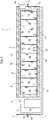
- numeral 1 indicates a battery pack for a hybrid vehicle or an electric vehicle, comprising a casing 2 including a lower casing element 3 having a bottom wall 4, two side walls 5 and two end walls 6.
- a cover 7 is mounted above the lower casing element 3, which delimits the space inside the casing, together with the lower element 3.
- a partition wall 8 ( Figure 3 ) is included, which defines a main chamber 8A inside the casing, in which a group 9 of battery cells is arranged, and an auxiliary chamber 8B, separated from the chamber 8A, in which an electronic control unit 10 and a unity 11 including a compressor with an associated electric drive motor are housed.
- the group of battery cells 9 includes an array of cells 12 arranged side-by-side to each other, but mutually spaced-apart. As illustrated in Figure 3 , the battery cells 12 are elongated in a direction transverse to the longitudinal direction of the casing 2 and fill the inner chamber 8A. The cells 12 have upper surfaces and lower surfaces substantially coplanar to each other.
- FIGS. 1 and 7A show an embodiment example of the casing 2, in which the lower element 3 of the casing and the cover 7 have peripheral coupling flanges 3A and 7A, which can be joined together by means of removable coupling means of any known type.
- the bottom wall 4 of the lower element 3 of the casing has its outer surface defining a plurality of parallel and spaced-apart fins 4A, for the object of increasing the surface of heat exchange with the external environment.
- the battery pack 1 includes an autonomous cooling system 13 including a circuit for a refrigerant fluid.
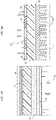
- This circuit comprises the compressor 11, driven by an electric motor, a condenser 14, which receives the compressed fluid from the compressor 11, an expansion device 15, for expanding the fluid coming from the condenser 14, an evaporator 16, which receives expanded fluid from the expansion device 15 and supplies it to the compressor 11.
- the expansion device 15 can also be formed by just one orifice provided in the line 17, which connects the outlet of the condenser 14 with the inlet of the evaporator 16.
- the condenser 14 and the evaporator 16 are each formed of a hollow panel, for example of metal material, having a single inner chamber communicating with an inlet and an outlet of the panel arranged on opposite sides of the panel.
- the panel forming the condenser 14 has an inlet 14A, which receives the compressed fluid from the compressor 11, and an outlet 14B from which the fluid is fed towards the expansion device 15.
- the panel forming the evaporator 16 has an inlet 16A, which receives expanded fluid from the expansion device 15, and an outlet 16B from which the fluid is supplied to the compressor 11.
- the two panels 14, 16 forming the condenser and the evaporator of the cooling system are arranged adjacent to two opposite major faces of the group 9 of the battery cells 12.
- the panel 14 forming the chamber of the cooling system rests on the inner surface of the bottom wall 4 inside the chamber 8A of the casing containing the 9 of the battery cells.
- the group 9 is placed above the panel 14 with the interposition of a wall 25 of thermally insulating material. This drastically reduces or completely eliminates any heat transfer from the condenser panel 14 to the battery cells 12, while the fins 4A of the bottom wall 4 of the casing encourage heat dissipation from the condenser panel 14.
- a wall 18 is provided within the casing 2, consisting of a PCM, which covers the upper side of the group 9 of the battery cells 12, filling the spaces between the individual cells 12, and also covers the end sides of the cells 12.
- the PCMs have been known and used for some time.
- any known PCM of the solid/liquid transition type can be provided.
- the evaporator panel 16 is embedded in the PCM wall 18.
- the function of the wall 18 is to make the temperature of the group of battery cells as uniform as possible.
- additional walls 19 of thermally insulating material are provided inside the casing 2 covering the upper side, the side surfaces and the end surfaces of the group 9 of the battery cells 12, inside the chamber 8A.
- electrical conductors 20 ( Figures 5 , 6 and 5B ) are provided in the form of strips parallel to each other and spaced apart, configured to act as heaters. These heaters are activated when the vehicle is in a very cold environment, whereby a battery cell heating 12 is required.
- control unit 10 automatically activates the cooling system 13 and the heaters 20 as a function of signals emitted by temperature sensors, including, for example, one or more temperature sensors of the battery cell group 9 (not illustrated) and an ambient temperature sensor.
- the control unit 10 is programmed according to one or more predetermined programs to ensure that the battery pack 1 always operates in an ideal temperature range for correct and efficient operation.
- the casing 1 can be provided with an opening 1A in which a compensation valve 21 of any known type is arranged, configured to uniform the pressures inside and outside the arranged, configured to uniform the pressures inside and outside the casing 2.
- a dehydrator device of any known type can also be associated with the battery pack.
- the battery pack according to the invention has a relatively simple and low-cost structure, and is able to operate efficiently, ensuring that the battery cells are constantly kept within a predetermined temperature range. All the aforesaid results are obtained with a battery pack that is dimensionally very compact, especially in the vertical direction, which makes it easy to place the battery pack in any suitable position within a vehicle.
Landscapes
- Engineering & Computer Science (AREA)
- Manufacturing & Machinery (AREA)
- Chemical & Material Sciences (AREA)
- Chemical Kinetics & Catalysis (AREA)
- Electrochemistry (AREA)
- General Chemical & Material Sciences (AREA)
- Life Sciences & Earth Sciences (AREA)
- Sustainable Development (AREA)
- Sustainable Energy (AREA)
- Power Engineering (AREA)
- Transportation (AREA)
- Mechanical Engineering (AREA)
- Battery Mounting, Suspending (AREA)
- Secondary Cells (AREA)
Claims (8)
- Batteriepack für ein Fahrzeug, insbesondere für ein Hybridfahrzeug oder ein Elektrofahrzeug, umfassend:- ein Gehäuse (2),- eine Gruppe (9) von Batteriezellen, die im Innern des Gehäuses (2) angeordnet sind,- einen Steuerkreis (10), der ebenfalls im Innern des Gehäuses (2) angeordnet ist,- ein unabhängiges Kühlsystem (13), das im Innern des Gehäuses (2) angeordnet und gestaltet ist, um die Batteriezellen (12) zu kühlen,wobei das Batteriepack (1) dadurch gekennzeichnet ist, dass das Kühlsystem (13), welches im Innern des Gehäuses des Batteriepacks angeordnet ist, einen Kreislauf für ein Kühlfluid (10) enthält, umfassend:- einen Kompressor (11), der von einem Elektromotor angetrieben wird,- einen Kühler (14), der komprimiertes Fluid von dem Kompressor (11) aufnimmt,- eine Expansionsvorrichtung (15) zum Expandieren des vom Kühler (14) kommenden Fluides, und- einen Verdampfer (16), der expandiertes Fluid von der Expansionsvorrichtung (15) aufnimmt und das Fluid dem Kompressor (11) zuführt,wobei- der Kühler (14) und der Verdampfer (16), die Teil des Kühlfluidkreislaufes bilden, aus zwei Hohlplatten bestehen, die zwei gegenüberliegenden Hauptflächen der Gruppe (9) von Batteriezellen benachbart angeordnet sind, wobei jede Hohlplatte eine einzelne innere Kammer aufweist, die mit einem Einlass (14B, 16B) und einem Auslass (14B, 16B) der Platte, die auf zwei gegenüberliegenden Seiten der Platte angeordnet sind, in Verbindung steht,- die den Kühler (14) des Kühlsystems (13) bildende Hohlplatte im Kontakt mit einer Bodenwand (4) des Gehäuses des Batteriepacks (1) unter der Gruppe (9) von Batteriezellen angeordnet ist,- eine Wand (25) aus thermisch isolierendem Material zwischen der Kühlerplatte (14) und der unteren Seite der Batteriezellengruppe (9) eingelegt ist,- die den Verdampfer (16) des Kühlsystems (13) bildende Hohlplatte über der Gruppe (9) von Batteriezellen angeordnet ist,- Wände (19) aus thermisch isolierendem Material über der Verdampferplatte (16) und über der Batteriezellengruppe (9) und um die Seitenwände der Batteriezellengruppe herum angeordnet sind.
- Batteriepack nach Anspruch 1, dadurch gekennzeichnet, dass die Bodenwand (4) des Gehäuses (2) eine Außenfläche aufweist, die eine Vielzahl von Kühlrippen (4A) bildet, die dazu bestimmt sind, die wärmetauschende Heizfläche mit der umliegenden Umgebung zu vergrößern.
- Batteriepack nach Anspruch 2, dadurch gekennzeichnet, dass die Bodenwand (4) Teil eines unteren Gehäuseelements (3) ist, welches die Bodenwand (4), zwei Seitenwände (5) und zwei Stirnwände (6) umfasst, und dadurch, dass das Gehäuse (2) außerdem eine obere Abdeckung (7) aufweist, die über dem unteren Gehäuseelement (3) befestigt ist.
- Batterieeinheit nach Anspruch 3, dadurch gekennzeichnet, dass das Gehäuse (2) eine innere Trennwand (8) aufweist, die eine die Gruppe (9) von Batteriezellen enthaltende erste Kammer (8A) und eine den Kompressor (11) und den Steuerkreis (10) enthaltende zweite Kammer (8B) bildet.
- Batteriepack nach Anspruch 1, dadurch gekennzeichnet, dass mindestens eine Wand (18) aus Phasenwechselmaterial zwischen der Gruppe (9) von Batteriezellen und den Wänden (19) aus thermisch isolierendem Material eingelegt ist.
- Batteriepack nach Anspruch 1, dadurch gekennzeichnet, dass elektrische Heizvorrichtungen zwischen der unteren Seite der Gruppe (9) von Batteriezellen und der Wand (25) aus dazugehörigem, thermisch isolierendem Material eingelegt sind.
- Batteriepack nach Anspruch 1, dadurch gekennzeichnet, dass das Gehäuse (2) eine Öffnung (1A) aufweist, in der ein Druckausgleichsventil (21) angeordnet ist, um den Druck zwischen der Umgebung im Innern des Gehäuses und der außen liegenden Umgebung auszugleichen.
- Batteriepack nach Anspruch 1, dadurch gekennzeichnet, dass es eine Trocknervorrichtung enthält, um Feuchtigkeit im Innern des Gehäuses (2) zu verringern.
Priority Applications (1)
| Application Number | Priority Date | Filing Date | Title |
|---|---|---|---|
| EP18168548.8A EP3556598B1 (de) | 2018-04-20 | 2018-04-20 | Batteriepack für ein fahrzeug, insbesondere ein hybrides oder elektrisches fahrzeug |
Applications Claiming Priority (1)
| Application Number | Priority Date | Filing Date | Title |
|---|---|---|---|
| EP18168548.8A EP3556598B1 (de) | 2018-04-20 | 2018-04-20 | Batteriepack für ein fahrzeug, insbesondere ein hybrides oder elektrisches fahrzeug |
Publications (2)
| Publication Number | Publication Date |
|---|---|
| EP3556598A1 EP3556598A1 (de) | 2019-10-23 |
| EP3556598B1 true EP3556598B1 (de) | 2022-05-04 |
Family
ID=62186222
Family Applications (1)
| Application Number | Title | Priority Date | Filing Date |
|---|---|---|---|
| EP18168548.8A Active EP3556598B1 (de) | 2018-04-20 | 2018-04-20 | Batteriepack für ein fahrzeug, insbesondere ein hybrides oder elektrisches fahrzeug |
Country Status (1)
| Country | Link |
|---|---|
| EP (1) | EP3556598B1 (de) |
Cited By (1)
| Publication number | Priority date | Publication date | Assignee | Title |
|---|---|---|---|---|
| EP4550528A1 (de) * | 2023-11-06 | 2025-05-07 | Deere & Company | Batteriesystem |
Families Citing this family (2)
| Publication number | Priority date | Publication date | Assignee | Title |
|---|---|---|---|---|
| CN111313123B (zh) * | 2020-02-27 | 2022-06-07 | 中国矿业大学 | 一种基于两级热管与车身结合的动力电池热管理系统 |
| FR3134481A1 (fr) * | 2022-04-07 | 2023-10-13 | Akwel | Unité de batterie pour véhicule automobile hybride ou électrique. |
Family Cites Families (4)
| Publication number | Priority date | Publication date | Assignee | Title |
|---|---|---|---|---|
| JP5330810B2 (ja) * | 2008-11-18 | 2013-10-30 | 株式会社日立製作所 | 電池モジュールを収容する電池箱及びそれを備える鉄道車両 |
| US20140011059A1 (en) * | 2011-03-31 | 2014-01-09 | Hiroyuki Hashimoto | Power supply device and vehicle equipped therewith |
| CN103419661B (zh) * | 2012-05-22 | 2015-12-02 | 比亚迪股份有限公司 | 电动汽车、电动汽车的动力系统及电池加热方法 |
| FR3008036B1 (fr) * | 2013-07-05 | 2015-06-26 | Renault Sa | Dispositif de gestion thermique de la batterie d'un vehicule electrique |
-
2018
- 2018-04-20 EP EP18168548.8A patent/EP3556598B1/de active Active
Cited By (1)
| Publication number | Priority date | Publication date | Assignee | Title |
|---|---|---|---|---|
| EP4550528A1 (de) * | 2023-11-06 | 2025-05-07 | Deere & Company | Batteriesystem |
Also Published As
| Publication number | Publication date |
|---|---|
| EP3556598A1 (de) | 2019-10-23 |
Similar Documents
| Publication | Publication Date | Title |
|---|---|---|
| JP5664690B2 (ja) | 電池パック | |
| EP3556598B1 (de) | Batteriepack für ein fahrzeug, insbesondere ein hybrides oder elektrisches fahrzeug | |
| US4644758A (en) | Refrigerated display cabinet | |
| US11326839B2 (en) | Thermal exchanger-accumulator | |
| US8726688B2 (en) | Refrigerator for fresh products with temperature leveling means | |
| US8967233B2 (en) | Latent cold storage device | |
| JP2012242075A (ja) | 冷蔵庫 | |
| KR101371362B1 (ko) | 멀티냉각방식 열교환기 일체형 p.c.m 축냉조 | |
| US20080148755A1 (en) | Cooling apparatus for on-vehicle electronic device | |
| WO2010143407A1 (ja) | 輸送用冷凍装置 | |
| EP1421323B1 (de) | Gehäuse mit thermischer wärmedämmung | |
| NL2015702B1 (en) | Cargo space unit for a vehicle. | |
| AU2001286740A1 (en) | Thermal barrier enclosure system | |
| CN113758339B (zh) | 单元配送箱及具有其的物流配送车 | |
| US9784490B2 (en) | Refrigeration system with humidity control | |
| CN114074515A (zh) | 热管理系统、车辆的空气调节系统、电池调温系统和车辆 | |
| JP2020201006A (ja) | 冷蔵庫 | |
| KR100336324B1 (ko) | 동시 냉, 온 저장이 가능한 냉온장고 | |
| ITMI20000784A1 (it) | Impianto per il mantenimento a bassa temperatura di un ambiente isotermico | |
| JP2011007369A (ja) | 輸送用冷凍装置 | |
| JP2022184713A (ja) | 輸送用コンテナの温度調節構造および温度調節方法 | |
| EP3882551A1 (de) | Wärmetauscher | |
| US20250377145A1 (en) | Ice making assembly for a refrigerator appliance | |
| KR20260030688A (ko) | 전기 차량용 가압 하의 저장 시스템 | |
| JP3243364B2 (ja) | 自動販売機 |
Legal Events
| Date | Code | Title | Description |
|---|---|---|---|
| PUAI | Public reference made under article 153(3) epc to a published international application that has entered the european phase |
Free format text: ORIGINAL CODE: 0009012 |
|
| STAA | Information on the status of an ep patent application or granted ep patent |
Free format text: STATUS: REQUEST FOR EXAMINATION WAS MADE |
|
| 17P | Request for examination filed |
Effective date: 20190513 |
|
| AK | Designated contracting states |
Kind code of ref document: A1 Designated state(s): AL AT BE BG CH CY CZ DE DK EE ES FI FR GB GR HR HU IE IS IT LI LT LU LV MC MK MT NL NO PL PT RO RS SE SI SK SM TR |
|
| AX | Request for extension of the european patent |
Extension state: BA ME |
|
| STAA | Information on the status of an ep patent application or granted ep patent |
Free format text: STATUS: EXAMINATION IS IN PROGRESS |
|
| 17Q | First examination report despatched |
Effective date: 20210125 |
|
| REG | Reference to a national code |
Ref country code: DE Ref legal event code: R079 Ref document number: 602018034787 Country of ref document: DE Free format text: PREVIOUS MAIN CLASS: B60L0011180000 Ipc: B60L0058240000 |
|
| GRAP | Despatch of communication of intention to grant a patent |
Free format text: ORIGINAL CODE: EPIDOSNIGR1 |
|
| STAA | Information on the status of an ep patent application or granted ep patent |
Free format text: STATUS: GRANT OF PATENT IS INTENDED |
|
| RIC1 | Information provided on ipc code assigned before grant |
Ipc: H01M 10/659 20140101ALI20220121BHEP Ipc: H01M 10/658 20140101ALI20220121BHEP Ipc: H01M 10/6569 20140101ALI20220121BHEP Ipc: H01M 10/625 20140101ALI20220121BHEP Ipc: H01M 10/613 20140101ALI20220121BHEP Ipc: H01M 6/50 20060101ALI20220121BHEP Ipc: B60L 58/26 20190101ALI20220121BHEP Ipc: B60L 58/24 20190101AFI20220121BHEP |
|
| INTG | Intention to grant announced |
Effective date: 20220208 |
|
| GRAS | Grant fee paid |
Free format text: ORIGINAL CODE: EPIDOSNIGR3 |
|
| GRAA | (expected) grant |
Free format text: ORIGINAL CODE: 0009210 |
|
| STAA | Information on the status of an ep patent application or granted ep patent |
Free format text: STATUS: THE PATENT HAS BEEN GRANTED |
|
| AK | Designated contracting states |
Kind code of ref document: B1 Designated state(s): AL AT BE BG CH CY CZ DE DK EE ES FI FR GB GR HR HU IE IS IT LI LT LU LV MC MK MT NL NO PL PT RO RS SE SI SK SM TR |
|
| REG | Reference to a national code |
Ref country code: GB Ref legal event code: FG4D |
|
| REG | Reference to a national code |
Ref country code: CH Ref legal event code: EP |
|
| REG | Reference to a national code |
Ref country code: AT Ref legal event code: REF Ref document number: 1488708 Country of ref document: AT Kind code of ref document: T Effective date: 20220515 |
|
| REG | Reference to a national code |
Ref country code: IE Ref legal event code: FG4D Ref country code: DE Ref legal event code: R096 Ref document number: 602018034787 Country of ref document: DE |
|
| REG | Reference to a national code |
Ref country code: LT Ref legal event code: MG9D |
|
| REG | Reference to a national code |
Ref country code: NL Ref legal event code: MP Effective date: 20220504 |
|
| REG | Reference to a national code |
Ref country code: AT Ref legal event code: MK05 Ref document number: 1488708 Country of ref document: AT Kind code of ref document: T Effective date: 20220504 |
|
| PG25 | Lapsed in a contracting state [announced via postgrant information from national office to epo] |
Ref country code: SE Free format text: LAPSE BECAUSE OF FAILURE TO SUBMIT A TRANSLATION OF THE DESCRIPTION OR TO PAY THE FEE WITHIN THE PRESCRIBED TIME-LIMIT Effective date: 20220504 Ref country code: PT Free format text: LAPSE BECAUSE OF FAILURE TO SUBMIT A TRANSLATION OF THE DESCRIPTION OR TO PAY THE FEE WITHIN THE PRESCRIBED TIME-LIMIT Effective date: 20220905 Ref country code: NO Free format text: LAPSE BECAUSE OF FAILURE TO SUBMIT A TRANSLATION OF THE DESCRIPTION OR TO PAY THE FEE WITHIN THE PRESCRIBED TIME-LIMIT Effective date: 20220804 Ref country code: NL Free format text: LAPSE BECAUSE OF FAILURE TO SUBMIT A TRANSLATION OF THE DESCRIPTION OR TO PAY THE FEE WITHIN THE PRESCRIBED TIME-LIMIT Effective date: 20220504 Ref country code: LT Free format text: LAPSE BECAUSE OF FAILURE TO SUBMIT A TRANSLATION OF THE DESCRIPTION OR TO PAY THE FEE WITHIN THE PRESCRIBED TIME-LIMIT Effective date: 20220504 Ref country code: HR Free format text: LAPSE BECAUSE OF FAILURE TO SUBMIT A TRANSLATION OF THE DESCRIPTION OR TO PAY THE FEE WITHIN THE PRESCRIBED TIME-LIMIT Effective date: 20220504 Ref country code: GR Free format text: LAPSE BECAUSE OF FAILURE TO SUBMIT A TRANSLATION OF THE DESCRIPTION OR TO PAY THE FEE WITHIN THE PRESCRIBED TIME-LIMIT Effective date: 20220805 Ref country code: FI Free format text: LAPSE BECAUSE OF FAILURE TO SUBMIT A TRANSLATION OF THE DESCRIPTION OR TO PAY THE FEE WITHIN THE PRESCRIBED TIME-LIMIT Effective date: 20220504 Ref country code: ES Free format text: LAPSE BECAUSE OF FAILURE TO SUBMIT A TRANSLATION OF THE DESCRIPTION OR TO PAY THE FEE WITHIN THE PRESCRIBED TIME-LIMIT Effective date: 20220504 Ref country code: BG Free format text: LAPSE BECAUSE OF FAILURE TO SUBMIT A TRANSLATION OF THE DESCRIPTION OR TO PAY THE FEE WITHIN THE PRESCRIBED TIME-LIMIT Effective date: 20220804 Ref country code: AT Free format text: LAPSE BECAUSE OF FAILURE TO SUBMIT A TRANSLATION OF THE DESCRIPTION OR TO PAY THE FEE WITHIN THE PRESCRIBED TIME-LIMIT Effective date: 20220504 |
|
| PG25 | Lapsed in a contracting state [announced via postgrant information from national office to epo] |
Ref country code: RS Free format text: LAPSE BECAUSE OF FAILURE TO SUBMIT A TRANSLATION OF THE DESCRIPTION OR TO PAY THE FEE WITHIN THE PRESCRIBED TIME-LIMIT Effective date: 20220504 Ref country code: PL Free format text: LAPSE BECAUSE OF FAILURE TO SUBMIT A TRANSLATION OF THE DESCRIPTION OR TO PAY THE FEE WITHIN THE PRESCRIBED TIME-LIMIT Effective date: 20220504 Ref country code: LV Free format text: LAPSE BECAUSE OF FAILURE TO SUBMIT A TRANSLATION OF THE DESCRIPTION OR TO PAY THE FEE WITHIN THE PRESCRIBED TIME-LIMIT Effective date: 20220504 Ref country code: IS Free format text: LAPSE BECAUSE OF FAILURE TO SUBMIT A TRANSLATION OF THE DESCRIPTION OR TO PAY THE FEE WITHIN THE PRESCRIBED TIME-LIMIT Effective date: 20220904 |
|
| PG25 | Lapsed in a contracting state [announced via postgrant information from national office to epo] |
Ref country code: SM Free format text: LAPSE BECAUSE OF FAILURE TO SUBMIT A TRANSLATION OF THE DESCRIPTION OR TO PAY THE FEE WITHIN THE PRESCRIBED TIME-LIMIT Effective date: 20220504 Ref country code: SK Free format text: LAPSE BECAUSE OF FAILURE TO SUBMIT A TRANSLATION OF THE DESCRIPTION OR TO PAY THE FEE WITHIN THE PRESCRIBED TIME-LIMIT Effective date: 20220504 Ref country code: RO Free format text: LAPSE BECAUSE OF FAILURE TO SUBMIT A TRANSLATION OF THE DESCRIPTION OR TO PAY THE FEE WITHIN THE PRESCRIBED TIME-LIMIT Effective date: 20220504 Ref country code: EE Free format text: LAPSE BECAUSE OF FAILURE TO SUBMIT A TRANSLATION OF THE DESCRIPTION OR TO PAY THE FEE WITHIN THE PRESCRIBED TIME-LIMIT Effective date: 20220504 Ref country code: DK Free format text: LAPSE BECAUSE OF FAILURE TO SUBMIT A TRANSLATION OF THE DESCRIPTION OR TO PAY THE FEE WITHIN THE PRESCRIBED TIME-LIMIT Effective date: 20220504 Ref country code: CZ Free format text: LAPSE BECAUSE OF FAILURE TO SUBMIT A TRANSLATION OF THE DESCRIPTION OR TO PAY THE FEE WITHIN THE PRESCRIBED TIME-LIMIT Effective date: 20220504 |
|
| REG | Reference to a national code |
Ref country code: DE Ref legal event code: R097 Ref document number: 602018034787 Country of ref document: DE |
|
| PLBE | No opposition filed within time limit |
Free format text: ORIGINAL CODE: 0009261 |
|
| STAA | Information on the status of an ep patent application or granted ep patent |
Free format text: STATUS: NO OPPOSITION FILED WITHIN TIME LIMIT |
|
| PG25 | Lapsed in a contracting state [announced via postgrant information from national office to epo] |
Ref country code: AL Free format text: LAPSE BECAUSE OF FAILURE TO SUBMIT A TRANSLATION OF THE DESCRIPTION OR TO PAY THE FEE WITHIN THE PRESCRIBED TIME-LIMIT Effective date: 20220504 |
|
| 26N | No opposition filed |
Effective date: 20230207 |
|
| PG25 | Lapsed in a contracting state [announced via postgrant information from national office to epo] |
Ref country code: SI Free format text: LAPSE BECAUSE OF FAILURE TO SUBMIT A TRANSLATION OF THE DESCRIPTION OR TO PAY THE FEE WITHIN THE PRESCRIBED TIME-LIMIT Effective date: 20220504 |
|
| REG | Reference to a national code |
Ref country code: CH Ref legal event code: PL |
|
| GBPC | Gb: european patent ceased through non-payment of renewal fee |
Effective date: 20230420 |
|
| PG25 | Lapsed in a contracting state [announced via postgrant information from national office to epo] |
Ref country code: LU Free format text: LAPSE BECAUSE OF NON-PAYMENT OF DUE FEES Effective date: 20230420 |
|
| REG | Reference to a national code |
Ref country code: BE Ref legal event code: MM Effective date: 20230430 |
|
| PG25 | Lapsed in a contracting state [announced via postgrant information from national office to epo] |
Ref country code: MC Free format text: LAPSE BECAUSE OF FAILURE TO SUBMIT A TRANSLATION OF THE DESCRIPTION OR TO PAY THE FEE WITHIN THE PRESCRIBED TIME-LIMIT Effective date: 20220504 |
|
| PG25 | Lapsed in a contracting state [announced via postgrant information from national office to epo] |
Ref country code: GB Free format text: LAPSE BECAUSE OF NON-PAYMENT OF DUE FEES Effective date: 20230420 |
|
| PG25 | Lapsed in a contracting state [announced via postgrant information from national office to epo] |
Ref country code: MC Free format text: LAPSE BECAUSE OF FAILURE TO SUBMIT A TRANSLATION OF THE DESCRIPTION OR TO PAY THE FEE WITHIN THE PRESCRIBED TIME-LIMIT Effective date: 20220504 Ref country code: LI Free format text: LAPSE BECAUSE OF NON-PAYMENT OF DUE FEES Effective date: 20230430 Ref country code: GB Free format text: LAPSE BECAUSE OF NON-PAYMENT OF DUE FEES Effective date: 20230420 Ref country code: CH Free format text: LAPSE BECAUSE OF NON-PAYMENT OF DUE FEES Effective date: 20230430 |
|
| REG | Reference to a national code |
Ref country code: IE Ref legal event code: MM4A |
|
| PG25 | Lapsed in a contracting state [announced via postgrant information from national office to epo] |
Ref country code: BE Free format text: LAPSE BECAUSE OF NON-PAYMENT OF DUE FEES Effective date: 20230430 |
|
| PG25 | Lapsed in a contracting state [announced via postgrant information from national office to epo] |
Ref country code: IE Free format text: LAPSE BECAUSE OF NON-PAYMENT OF DUE FEES Effective date: 20230420 |
|
| PG25 | Lapsed in a contracting state [announced via postgrant information from national office to epo] |
Ref country code: IE Free format text: LAPSE BECAUSE OF NON-PAYMENT OF DUE FEES Effective date: 20230420 |
|
| PG25 | Lapsed in a contracting state [announced via postgrant information from national office to epo] |
Ref country code: BG Free format text: LAPSE BECAUSE OF FAILURE TO SUBMIT A TRANSLATION OF THE DESCRIPTION OR TO PAY THE FEE WITHIN THE PRESCRIBED TIME-LIMIT Effective date: 20220504 |
|
| PG25 | Lapsed in a contracting state [announced via postgrant information from national office to epo] |
Ref country code: BG Free format text: LAPSE BECAUSE OF FAILURE TO SUBMIT A TRANSLATION OF THE DESCRIPTION OR TO PAY THE FEE WITHIN THE PRESCRIBED TIME-LIMIT Effective date: 20220504 |
|
| PGFP | Annual fee paid to national office [announced via postgrant information from national office to epo] |
Ref country code: DE Payment date: 20250319 Year of fee payment: 8 |
|
| PG25 | Lapsed in a contracting state [announced via postgrant information from national office to epo] |
Ref country code: CY Free format text: LAPSE BECAUSE OF FAILURE TO SUBMIT A TRANSLATION OF THE DESCRIPTION OR TO PAY THE FEE WITHIN THE PRESCRIBED TIME-LIMIT; INVALID AB INITIO Effective date: 20180420 |
|
| PG25 | Lapsed in a contracting state [announced via postgrant information from national office to epo] |
Ref country code: HU Free format text: LAPSE BECAUSE OF FAILURE TO SUBMIT A TRANSLATION OF THE DESCRIPTION OR TO PAY THE FEE WITHIN THE PRESCRIBED TIME-LIMIT; INVALID AB INITIO Effective date: 20180420 |
|
| PG25 | Lapsed in a contracting state [announced via postgrant information from national office to epo] |
Ref country code: TR Free format text: LAPSE BECAUSE OF FAILURE TO SUBMIT A TRANSLATION OF THE DESCRIPTION OR TO PAY THE FEE WITHIN THE PRESCRIBED TIME-LIMIT Effective date: 20220504 |
|
| REG | Reference to a national code |
Ref country code: DE Ref legal event code: R081 Ref document number: 602018034787 Country of ref document: DE Owner name: STELLANTIS EUROPE S.P.A., IT Free format text: FORMER OWNER: FCA ITALY S.P.A., TORINO, IT |
|
| PGFP | Annual fee paid to national office [announced via postgrant information from national office to epo] |
Ref country code: IT Payment date: 20260319 Year of fee payment: 9 |
|
| PGFP | Annual fee paid to national office [announced via postgrant information from national office to epo] |
Ref country code: FR Payment date: 20260320 Year of fee payment: 9 |