EP3556592A1 - Verfahren zur rückgewinnung von energie des verbrennungsmotors sowie steuergerät zur durchführung des verfahrens - Google Patents
Verfahren zur rückgewinnung von energie des verbrennungsmotors sowie steuergerät zur durchführung des verfahrens Download PDFInfo
- Publication number
- EP3556592A1 EP3556592A1 EP19166781.5A EP19166781A EP3556592A1 EP 3556592 A1 EP3556592 A1 EP 3556592A1 EP 19166781 A EP19166781 A EP 19166781A EP 3556592 A1 EP3556592 A1 EP 3556592A1
- Authority
- EP
- European Patent Office
- Prior art keywords
- combustion engine
- internal combustion
- kinetic energy
- transmission
- electric machine
- Prior art date
- Legal status (The legal status is an assumption and is not a legal conclusion. Google has not performed a legal analysis and makes no representation as to the accuracy of the status listed.)
- Granted
Links
Images


Classifications
-
- B—PERFORMING OPERATIONS; TRANSPORTING
- B60—VEHICLES IN GENERAL
- B60K—ARRANGEMENT OR MOUNTING OF PROPULSION UNITS OR OF TRANSMISSIONS IN VEHICLES; ARRANGEMENT OR MOUNTING OF PLURAL DIVERSE PRIME-MOVERS IN VEHICLES; AUXILIARY DRIVES FOR VEHICLES; INSTRUMENTATION OR DASHBOARDS FOR VEHICLES; ARRANGEMENTS IN CONNECTION WITH COOLING, AIR INTAKE, GAS EXHAUST OR FUEL SUPPLY OF PROPULSION UNITS IN VEHICLES
- B60K6/00—Arrangement or mounting of plural diverse prime-movers for mutual or common propulsion, e.g. hybrid propulsion systems comprising electric motors and internal combustion engines
- B60K6/20—Arrangement or mounting of plural diverse prime-movers for mutual or common propulsion, e.g. hybrid propulsion systems comprising electric motors and internal combustion engines the prime-movers consisting of electric motors and internal combustion engines, e.g. HEVs
- B60K6/22—Arrangement or mounting of plural diverse prime-movers for mutual or common propulsion, e.g. hybrid propulsion systems comprising electric motors and internal combustion engines the prime-movers consisting of electric motors and internal combustion engines, e.g. HEVs characterised by apparatus, components or means specially adapted for HEVs
- B60K6/38—Arrangement or mounting of plural diverse prime-movers for mutual or common propulsion, e.g. hybrid propulsion systems comprising electric motors and internal combustion engines the prime-movers consisting of electric motors and internal combustion engines, e.g. HEVs characterised by apparatus, components or means specially adapted for HEVs characterised by the driveline clutches
- B60K6/387—Actuated clutches, i.e. clutches engaged or disengaged by electric, hydraulic or mechanical actuating means
-
- B—PERFORMING OPERATIONS; TRANSPORTING
- B60—VEHICLES IN GENERAL
- B60K—ARRANGEMENT OR MOUNTING OF PROPULSION UNITS OR OF TRANSMISSIONS IN VEHICLES; ARRANGEMENT OR MOUNTING OF PLURAL DIVERSE PRIME-MOVERS IN VEHICLES; AUXILIARY DRIVES FOR VEHICLES; INSTRUMENTATION OR DASHBOARDS FOR VEHICLES; ARRANGEMENTS IN CONNECTION WITH COOLING, AIR INTAKE, GAS EXHAUST OR FUEL SUPPLY OF PROPULSION UNITS IN VEHICLES
- B60K6/00—Arrangement or mounting of plural diverse prime-movers for mutual or common propulsion, e.g. hybrid propulsion systems comprising electric motors and internal combustion engines
- B60K6/20—Arrangement or mounting of plural diverse prime-movers for mutual or common propulsion, e.g. hybrid propulsion systems comprising electric motors and internal combustion engines the prime-movers consisting of electric motors and internal combustion engines, e.g. HEVs
- B60K6/42—Arrangement or mounting of plural diverse prime-movers for mutual or common propulsion, e.g. hybrid propulsion systems comprising electric motors and internal combustion engines the prime-movers consisting of electric motors and internal combustion engines, e.g. HEVs characterised by the architecture of the hybrid electric vehicle
- B60K6/48—Parallel type
-
- B—PERFORMING OPERATIONS; TRANSPORTING
- B60—VEHICLES IN GENERAL
- B60W—CONJOINT CONTROL OF VEHICLE SUB-UNITS OF DIFFERENT TYPE OR DIFFERENT FUNCTION; CONTROL SYSTEMS SPECIALLY ADAPTED FOR HYBRID VEHICLES; ROAD VEHICLE DRIVE CONTROL SYSTEMS FOR PURPOSES NOT RELATED TO THE CONTROL OF A PARTICULAR SUB-UNIT
- B60W10/00—Conjoint control of vehicle sub-units of different type or different function
- B60W10/04—Conjoint control of vehicle sub-units of different type or different function including control of propulsion units
- B60W10/06—Conjoint control of vehicle sub-units of different type or different function including control of propulsion units including control of combustion engines
-
- B—PERFORMING OPERATIONS; TRANSPORTING
- B60—VEHICLES IN GENERAL
- B60W—CONJOINT CONTROL OF VEHICLE SUB-UNITS OF DIFFERENT TYPE OR DIFFERENT FUNCTION; CONTROL SYSTEMS SPECIALLY ADAPTED FOR HYBRID VEHICLES; ROAD VEHICLE DRIVE CONTROL SYSTEMS FOR PURPOSES NOT RELATED TO THE CONTROL OF A PARTICULAR SUB-UNIT
- B60W10/00—Conjoint control of vehicle sub-units of different type or different function
- B60W10/04—Conjoint control of vehicle sub-units of different type or different function including control of propulsion units
- B60W10/08—Conjoint control of vehicle sub-units of different type or different function including control of propulsion units including control of electric propulsion units, e.g. motors or generators
-
- B—PERFORMING OPERATIONS; TRANSPORTING
- B60—VEHICLES IN GENERAL
- B60W—CONJOINT CONTROL OF VEHICLE SUB-UNITS OF DIFFERENT TYPE OR DIFFERENT FUNCTION; CONTROL SYSTEMS SPECIALLY ADAPTED FOR HYBRID VEHICLES; ROAD VEHICLE DRIVE CONTROL SYSTEMS FOR PURPOSES NOT RELATED TO THE CONTROL OF A PARTICULAR SUB-UNIT
- B60W10/00—Conjoint control of vehicle sub-units of different type or different function
- B60W10/10—Conjoint control of vehicle sub-units of different type or different function including control of change-speed gearings
- B60W10/11—Stepped gearings
- B60W10/113—Stepped gearings with two input flow paths, e.g. double clutch transmission selection of one of the torque flow paths by the corresponding input clutch
-
- B—PERFORMING OPERATIONS; TRANSPORTING
- B60—VEHICLES IN GENERAL
- B60W—CONJOINT CONTROL OF VEHICLE SUB-UNITS OF DIFFERENT TYPE OR DIFFERENT FUNCTION; CONTROL SYSTEMS SPECIALLY ADAPTED FOR HYBRID VEHICLES; ROAD VEHICLE DRIVE CONTROL SYSTEMS FOR PURPOSES NOT RELATED TO THE CONTROL OF A PARTICULAR SUB-UNIT
- B60W20/00—Control systems specially adapted for hybrid vehicles
- B60W20/10—Controlling the power contribution of each of the prime movers to meet required power demand
- B60W20/13—Controlling the power contribution of each of the prime movers to meet required power demand in order to stay within battery power input or output limits; in order to prevent overcharging or battery depletion
-
- B—PERFORMING OPERATIONS; TRANSPORTING
- B60—VEHICLES IN GENERAL
- B60W—CONJOINT CONTROL OF VEHICLE SUB-UNITS OF DIFFERENT TYPE OR DIFFERENT FUNCTION; CONTROL SYSTEMS SPECIALLY ADAPTED FOR HYBRID VEHICLES; ROAD VEHICLE DRIVE CONTROL SYSTEMS FOR PURPOSES NOT RELATED TO THE CONTROL OF A PARTICULAR SUB-UNIT
- B60W20/00—Control systems specially adapted for hybrid vehicles
- B60W20/10—Controlling the power contribution of each of the prime movers to meet required power demand
- B60W20/15—Control strategies specially adapted for achieving a particular effect
- B60W20/16—Control strategies specially adapted for achieving a particular effect for reducing engine exhaust emissions
-
- B—PERFORMING OPERATIONS; TRANSPORTING
- B60—VEHICLES IN GENERAL
- B60W—CONJOINT CONTROL OF VEHICLE SUB-UNITS OF DIFFERENT TYPE OR DIFFERENT FUNCTION; CONTROL SYSTEMS SPECIALLY ADAPTED FOR HYBRID VEHICLES; ROAD VEHICLE DRIVE CONTROL SYSTEMS FOR PURPOSES NOT RELATED TO THE CONTROL OF A PARTICULAR SUB-UNIT
- B60W20/00—Control systems specially adapted for hybrid vehicles
- B60W20/40—Controlling the engagement or disengagement of prime movers, e.g. for transition between prime movers
-
- Y—GENERAL TAGGING OF NEW TECHNOLOGICAL DEVELOPMENTS; GENERAL TAGGING OF CROSS-SECTIONAL TECHNOLOGIES SPANNING OVER SEVERAL SECTIONS OF THE IPC; TECHNICAL SUBJECTS COVERED BY FORMER USPC CROSS-REFERENCE ART COLLECTIONS [XRACs] AND DIGESTS
- Y02—TECHNOLOGIES OR APPLICATIONS FOR MITIGATION OR ADAPTATION AGAINST CLIMATE CHANGE
- Y02T—CLIMATE CHANGE MITIGATION TECHNOLOGIES RELATED TO TRANSPORTATION
- Y02T10/00—Road transport of goods or passengers
- Y02T10/60—Other road transportation technologies with climate change mitigation effect
- Y02T10/62—Hybrid vehicles
-
- Y—GENERAL TAGGING OF NEW TECHNOLOGICAL DEVELOPMENTS; GENERAL TAGGING OF CROSS-SECTIONAL TECHNOLOGIES SPANNING OVER SEVERAL SECTIONS OF THE IPC; TECHNICAL SUBJECTS COVERED BY FORMER USPC CROSS-REFERENCE ART COLLECTIONS [XRACs] AND DIGESTS
- Y02—TECHNOLOGIES OR APPLICATIONS FOR MITIGATION OR ADAPTATION AGAINST CLIMATE CHANGE
- Y02T—CLIMATE CHANGE MITIGATION TECHNOLOGIES RELATED TO TRANSPORTATION
- Y02T10/00—Road transport of goods or passengers
- Y02T10/80—Technologies aiming to reduce greenhouse gasses emissions common to all road transportation technologies
- Y02T10/92—Energy efficient charging or discharging systems for batteries, ultracapacitors, supercapacitors or double-layer capacitors specially adapted for vehicles
Definitions
- the invention relates to methods for recovering energy of an internal combustion engine and control device for carrying out the method.
- a planetary gear arrangement optionally in conjunction with a continuously variable transmission.
- the integration of a dual-clutch transmission in a hybrid drive train is particularly advantageous, in particular when the electric machine is connected to the input of a partial transmission.
- the dual-clutch transmission is able to automatically engage and disengage when the internal combustion engine (VM) is disconnected. It is thus prepared for a start / stop system and an extended sailing function in which the vehicle rolls freely with the combustion engine disconnected.
- the electrical actuator also allows easy hybridization of the transmission, through an additional e-machine.
- the different hybrid powertrains offer the possibility of recovering the energy that the vehicle has in operation in many different ways.
- the simplest example is the recovery of energy from the braking of the vehicle is known, which returns with an efficiency over 80% energy in the drive process.
- the object is achieved with a method of recovering kinetic energy of an internal combustion engine by reducing the rotational speed of the internal combustion engine during a predetermined time in a vehicle and converting the kinetic energy of the rotation of the internal combustion engine or a drive unit into electrical energy by at least one electrical machine.
- the stored energy in the rotation of the internal combustion engine is tapped either directly on the engine or on a drive unit, a rotating shaft.
- the other alternative is that the internal combustion engine is decoupled and at least a portion of the kinetic energy of the expiring output is recovered.
- the method is implemented in a dual-clutch transmission, wherein the electric machine that is used to recover the energy in a dual-clutch transmission with a first and second partial transmission can be coupled to a partial transmission.
- the energy is advantageously recovered so that the energy of the expiring internal combustion engine by means of a first clutch and places a torque in the first partial transmission and a reduction of the torque of the electric machines. So here is not the electric machine operated as a generator, but the energy is used to reduce the electrical power supply side of the electric machine.
- the electric machine is operated as a generator.
- the torque of the electric machine is reduced absolutely, so either less motor torque or more regenerative torque. In both cases, electrical energy is saved.
- the speed of the internal combustion engine is greater than or equal to the speed of the first partial transmission.
- the electric machine is a starter generator, which acts on the internal combustion engine, or the electric machine of the dual-clutch transmission, which runs in the recuperation mode.
- FIG. 5 is schematically illustrated a hybrid solution with the integration of an electric motor EM in a dual-clutch transmission.
- the arrangement has a starter generator 13.
- the solution according to the invention can be carried out both with the hybridization dual-clutch transmission alone and with the starter generator alone.
- the electric machine in the drive system for the invention can be used.
- the powertrain 10 includes an engine VM connected to a starter generator 13. Furthermore, the drive train 10 includes a dual-clutch transmission 14 whose output side is connected to a differential 16. The differential 16 distributes drive power to left and right driven wheels 18L, 18R.
- the dual-clutch transmission 14 includes a first friction clutch 30 and a first partial transmission TG 1 .
- the first partial transmission TG 1 includes, for example Gear stages N, 1, 3, 5, etc. which can be engaged and disengaged by means of schematically indicated clutches 34.
- the first friction clutch 30 and the first partial transmission TG 1 form a first power transmission path 36 for transmitting power from the drive motor VM to the differential 16.
- the dual-clutch transmission 14 further includes a second friction clutch 20 and a second partial transmission TG 2 .
- the second partial transmission TG 2 includes, for example, the odd gear ratios N, 2, 4, 6, R, which are switched on and interpreted by means of associated clutches 24.
- the second friction clutch 20 and the second partial transmission TG 2 form a second power transmission path 26 for transmitting drive power from the drive motor VM to the differential 16.
- the powertrain 10 includes an electric machine EM, which is connected to a controller 42 for driving and power supply.
- the controller 42 may also include power electronics and a battery.
- the electric machine EM is fixedly connected to the second partial transmission TG 2 , for example by means of a spur gear or the like.
- the electric machine EM can be connected by means of a coupling arrangement to the second partial transmission TG 2 .
- connection of the electric machine EM to the second partial transmission TG 2 which has a high gear and the reverse gear, allows electric driving in almost all operating situations.
- the powertrain 10 is configured to operate in three different modes.
- a conventional drive mode drive power is generated only by the drive motor, the engine VM.
- Gear changes take place in an interruption-free manner by driving power being supplied via one of the power transmission paths 26, 36, wherein a gear stage is preselected in the partial transmission of the other power transmission path. Subsequently, a gear change takes place by transferring the power transmission flow from one path to the other path by the friction clutches 20, 30 are operated in an overlapping manner.
- This drive mode is well known in the art of dual clutch transmissions.
- a second hybrid drive mode may be arranged in which drive power is provided from both the engine VM and the electric machine EM. In this case, the drive powers can be added substantially over the summation point at the input of the second subtransmission TG 2 .
- the electric machine EM recuperates energy via the drive wheels 18 R and 18 L and the second partial transmission TG 2 .
- the solution is described, as it can be displayed using a hybridized dual-clutch transmission.
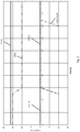
- Fig. 1 shows the situation how it works without a special solution for recovering energy in a dual-clutch transmission.
- the two partial transmissions of the dual-clutch gearbox rotate at different speeds.
- the internal combustion engine VM is coupled to the second partial transmission TG 2 , which rotates at 2000 rpm, which is shown in the figure with the broken line ins2_spd.
- the first partial transmission TG 1 rotates at a speed of 1000 revolutions / min and is represented by the graph ins1_spd.
- the engine VM is turned off and the second clutch 20 of the second gear TG 2 opens.
- the speed of the engine should then drop quickly, the desired drop in the combustion speed tgt_eng_spd follows that of the dotted line in Fig. 1 ,
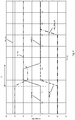
- FIG. 2 is a representation of the torques over time on the same scale as FIG. 1 ,
- the resulting output torque available for propulsion of the vehicle is represented by the top horizontal line out_tq. Since the illustrated solution is a solution in a dual-clutch transmission with an electric machine, the course of the torque of the electric machine EM_tq can also be found in this illustration. Their torque EM_tq is reduced from 30 Nm to 20 Nm at 0.5 seconds at the time the engine VM stops. From 0.5 seconds on the output there is no drag torque from the burner as the clutch opens. In order to maintain the same output torque, therefore, less torque of the electric machine EM is required (30 Nm -> 20 Nm).
- the torque of the first partial transmission runs along the zero line with ins1_tq, while the second partial transmission initially still has a torque ins2_tq and is connected drive-technically.
- the torque of the internal combustion engine follows the dashed line eng_drag_tq, which shows that the internal combustion engine nachdollelt and nachlauf after stopping the combustion process even at 0.5 seconds to 1.7 seconds.
- the two partial transmissions turn again with different rotational speeds.
- the first partial transmission TG 1 rotates at 2000 revolutions / min ins1_spd
- the second part transmission TG 2 rotates at 1000 revolutions / min, ins2_spd.
- the drop in the rotational speed of the internal combustion engine again follows the graph eng_spd, after switching off the internal combustion engine VM at 0.5 s.
- energy can be obtained.
- FIG. 4 In the FIG. 4 is shown how the transmission is made to partially recover the rotational energy of the engine VM can.
- the second clutch 20 of the second subtransmission TG 2 is opened.
- the goal is to decelerate the combustion engine faster and recover the energy.
- the first clutch 30 of the first partial transmission TG 1 is provided with a torque ins1_tq of 20 Nm.
- the torque EM_tq of the electric machine EM is reduced.
- the engine VM is slowed down a little faster and the energy of rotation contained in it is used by the electric machine EM has to deliver less power. or can generate more.
- the torque EM_tq of the electric machine EM is reduced below the target torque during the time t in which the first partial transmission sets a torque.
- the removal of the energy can be recognized by the fact that the internal combustion engine flies faster, namely only up to a time of 1.5 seconds in the graph, i. E. its residual energy is not that high anymore. However, the residual energy can not be completely recovered in a dual clutch transmission with hybridization. For the recovery of energy, the speed of the engine VM must be above the speed of the slower part of the transmission.
- Another possibility of energy recovery in a hybridized dual-clutch transmission is that the electric machine EM is loaded by opening the clutch 20 of the second sub-transmission, which is set neutral.
- the situation is different in a solution in which the starter generator 13 connected independently of a gearbox to the system engine with gearbox is.
- the starter generator When using a starter generator with the requirement that the engine should be turned off, the starter generator, a high regenerative torque can be generated to bring the engine VM as fast as possible to the target speed and the kinetic energy of the engine VM as good as possible regain.
- the connection of the starter generator only needs to be in front of the gearbox. In this type of energy recovery, the gear type is not important.
- the complete residual energy of the internal combustion engine VM can be recovered after switching off via the starter generator 13 and stored as electrical energy.
- This method of energy recovery is suitable for vehicles equipped with automatic start-stop.
- the starter generator can recover the remaining energy of the internal combustion engine VM almost to standstill.
- the entire idea of recovering electrical energy during the combustion stop can also be realized when disconnecting the internal combustion engine VM from the drive train. Once the engine VM is decoupled from the powertrain in the condition of sailing, the energy contained in the coasting of the engine RPM VM can be recovered.
- the type of connected gear is not important. If a starter generator is present, this energy can also be recovered with high yield.
- the realization of the method according to the invention takes place in a software solution which can be contained in the vehicle control system, more precisely in either a motor control, a transmission control or a combination of the controls.
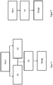
- the inventive method is schematically again in the FIGS. 6 and 7 shown.
- the procedure starts with the block "Start", which can be triggered by different processes.
- the start can be initiated by switching off the internal combustion engine VM.
- the start can also be triggered by the decoupling of the internal combustion engine VM from the drive train.
- the start of the method can also be triggered by reducing the request to the internal combustion engine VM.
- step S1 a torque is set with the first clutch 30 of the first partial transmission TG 1 , while the second clutch 20 is opened. At the same time, the torque of the electric machine is reduced below the setpoint in S2.
- step S3 This state continues during the time t, which is shown in step S3.
- the electric machine consumes less energy.
- the speed difference between the engine VM and the faster rotating shaft of the partial transmission is used up.
- the speed difference between the output shaft of the internal combustion engine and the faster rotating shaft of the partial transmission is used up.
- FIG. 7 schematically represents the simplified solution, when the energy of the engine VM when parking or when disconnecting directly to a starter generator or decoupled from the rest of the transmission, electrical machine is issued in the transmission.
- Such an arrangement can be a connection of the include electrical machines input side of the transmission, or a connection on the output side of a shaft.
- step S4 the electric machine that is to operate as a generator is connected to the rotating vehicle element and thus the kinetic energy is converted into electrical energy.
- the process is stopped when either the engine VM has come to a complete halt or has reached its target speed in an alternative solution - it may also be idle instead of idle - or the energy recovery in the generator for efficiency reasons no longer runs.
- the method is applicable to different hybrid arrangements. It is also an arrangement of the electric machine EM input side in front of the transmission or an arrangement of the electric machine EM at the transmission output with direct connection to the output shaft of the transmission.
Landscapes
- Engineering & Computer Science (AREA)
- Chemical & Material Sciences (AREA)
- Combustion & Propulsion (AREA)
- Transportation (AREA)
- Mechanical Engineering (AREA)
- Automation & Control Theory (AREA)
- Hybrid Electric Vehicles (AREA)
- Control Of Vehicle Engines Or Engines For Specific Uses (AREA)
Abstract
Description
- Die Erfindung betrifft Verfahren zur Rückgewinnung von Energie eines Verbrennungsmotors sowie Steuergerät zur Durchführung des Verfahrens.
- Die auf dem Gebiet der Kraftfahrzeugtechnik besteht seit einigen Jahren ein Trend hin zu Hybridfahrzeugen, bei denen die Antriebsleistung mittels eines Verbrennungsmotor (VM)s und mittels einer elektrischen Maschine bereitgestellt werden kann. Hierbei wird generell unterschieden zwischen sogenannten milden Hybrid Anwendungen, bei denen die elektrische Maschine lediglich kurzzeitig als alleinige Antriebsquelle verwendbar ist bzw. überwiegend als Boost-Antrieb eingesetzt wird. In sogenannten Range-Extender- Antriebssträngen dient eine elektrische Maschine hingegen als Hauptantriebsmotor und der Verbrennungsmotor wird zum Laden einer Batterie mitgeführt. Hinsichtlich des Layouts von solchen Antriebssträngen besteht die Möglichkeit den Verbrennungsmotor die elektrische Antriebsmaschine in Leistungsflussrichtung vor einer Kupplungsanordnung anzuordnen. Dieses Layout ist konstruktiv vergleichsweise einfach realisierbar, hat jedoch funktionelle Einschränkungen. In derartigen Hybrid Antriebsträngen wird als Getriebeanordnung häufig eine Planetengetriebe-Anordnung gegebenenfalls in Verbindung mit einem stufenlosen Getriebe verwendet. Besonders vorteilhaft ist jedoch die Integration eines Doppelkupplungsgetriebes in einem Hybrid-Antriebstrang, insbesondere dann, wenn die elektrische Maschine mit dem Eingang eines Teilgetriebes verbunden ist.
- Aus der
DE 10 2010 044 618 A1 ist ein Doppelkupplungsgetriebe mit nasser Doppelkupplung, elektromechanischer Betätigung des Schaltsystems und einer elektrohydraulischen Aktuatorik für die Doppelkupplung bekannt. - Mit der elektrischen Aktuatorik ist das Doppelkupplungsgetriebe in der Lage, bei abgetrenntem Verbrennungsmotor (VM) automatisch zu kuppeln und zu schalten. Es ist somit vorbereitet für ein Start/Stopp-System und eine erweiterte Segelfunktion, bei der das Fahrzeug bei abgekoppeltem Verbrennungsmotor frei rollt. Die elektrische Aktuatorik ermöglicht darüber hinaus die einfache Hybridisierung des Getriebes, durch eine zusätzliche E-Maschine.
- Durch die Verschärfung der Abgasvorschriften für Verbrennungsfahrzeuge ist es sinnvoll, jede auch kleinere Einsparungen an fossilen Brennstoffen und somit an Abgasen umzusetzen.
- Die unterschiedlichen Hybrid-Antriebstränge bieten die Möglichkeit, Energie, die das Fahrzeug ein Betrieb enthält, auf die unterschiedlichste Art und Weise zurück zu gewinnen. Als einfachstes Beispiel ist dabei die Rückgewinnung von Energie aus den Bremsvorgängen des Fahrzeugs bekannt, die mit einem Wirkungsgrad über 80% Energie in den Antriebsprozess rückführt.
- Allerdings gibt es im Fahrzeug noch weitere Bereiche, die bezüglich einer Energierückgewinnung betrachtet werden können.
- Auch ein Verbrennungsmotor, der nach dem Abschalten der Zündung ausläuft oder auch nur von seiner Arbeitsdrehzahl in die Leerlaufdrehzahl absinkt, enthält Rotationsenergie, die bisher ohne Nutzung als Schleppverlust lediglich in Wärme umgewandelt wird.
- Es ist Aufgabe der Erfindung, ein Verfahren zur Rückgewinnung von Energie aus einem Verbrennungsmotor vorzustellen.
- Die Aufgabe wird gelöst mit einem Verfahren von Rückgewinnen von kinetischer Energie eines Verbrennungsmotors durch Reduktion der Drehzahl des Verbrennungsmotors während einer vorgegebenen Zeit in einem Fahrzeug und Umwandlung der kinetischen Energie der Rotation des Verbrennungsmotors oder einer Antriebseinheit in elektrische Energie durch mindestens eine elektrische Maschine.
- Durch die Rückgewinnung der Energie des Verbrennungsmotors kann der Energieverbrauch des Gesamtfahrzeuges reduziert werden. Die Energie, die ansonsten durch Schleppverluste verschwindet, wird sinnvoll verwendet. Die noch in der Rotation des Verbrennungsmotors gespeicherte Energie wird entweder direkt am Verbrennungsmotor oder an einer Antriebseinheit, einer sich drehenden Welle abgegriffen.
- Es ist dabei eine Alternative, dass der Verbrennungsmotor abgeschaltet wird und zumindest ein Teil der kinetischen Energie des auslaufenden Verbrennungsmotors rückgewonnen wird.
- Die andere Alternative besteht darin, dass der Verbrennungsmotor abgekoppelt wird und zumindest ein Teil der kinetischen Energie des auslaufenden Abtriebs rückgewonnen wird.
- In einer besonders vorteilhaften Ausführungsform wird das Verfahren in einem Doppelkupplungsgetriebe umgesetzt, wobei die elektrische Maschine, die zur Rückgewinnung der Energie eingesetzt wird, in einem Doppelkupplungsgetriebe mit einem ersten und zweiten Teilgetriebe an einem Teilgetriebe ankoppelbar ist.
- Dabei wird vorteilhafterweise die Energie so zurückgewonnen, dass die Energie des auslaufenden Verbrennungsmotors mittels einer ersten Kupplung und Stellen eines Drehmoments im ersten Teilgetriebe und einer Reduktion des Drehmoments der elektrischen Maschinen erfolgt. Hier wird also die elektrische Maschine nicht als Generator betrieben, sondern die Energie wird zur Reduktion der elektrischen Energieversorgungsseite der elektrischen Maschine verwendet.
- Es kann aber auch sein, dass die elektrische Maschine als Generator betrieben wird. Bei diesem Verfahren wird das Drehmoment der elektrischen Maschine absolut reduziert, also entweder weniger motorisches Drehmoment oder mehr generatorisches Drehmoment. In beiden Fällen wird elektrische Energie gespart.
- Um das Verfahren durchzuführen, ist es notwendig, dass die Drehzahl des Verbrennungsmotors größer oder gleich der Drehzahl des ersten Teilgetriebes ist.
- In einer alternativen Ausführungsform ist die elektrische Maschine ein Startergenerator, der am Verbrennungsmotor angreift, oder die elektrische Maschine des Doppelkupplungsgetriebes, die im Rekuperationsbetrieb läuft.
- Das erfindungsgemäße Verfahren weist einen Verfahrensstart auf, der durch das Abschalten des Verbrennungsmotors und/oder durch das Abkoppeln des Verbrennungsmotors vom Antriebsstrang und/oder durch Reduktion der Anforderung an den Verbrennungsmotor ausgelöst wird.
- Das erfindungsgemäße Verfahren wird gestoppt, wenn der Verbrennungsmotor zum Stillstand gekommen ist oder unter eine Grenzdrehzahl fällt oder der Generatorwirkungsgrad unter eine Schwelle fällt.
- Die Aufgabe wird gelöst mit einer Steuerung zur Durchführung des Verfahrens, wobei die Steuerung eine Motorsteuerung und/oder eine Getriebesteuerung mit jeweiligen Datenaustausch ist.
- Die Erfindung wird nachfolgend beispielhaft unter Bezugnahme auf die beigefügte Zeichnung beschrieben.
-
Fig. 1 und2 zeigen den zeitlichen Verlauf von Drehzahlen und Drehmomenten im Stand der Technik, -
Figur 3 und4 zeigen den zeitlichen Verlauf von Drehzahlen und Drehmomenten mit einer Ausführungsform der erfinderischen Lösung, -
Fig. 5 zeigt eine schematische Darstellung der Hybrid-Architektur in zwei unterschiedlichen Varianten, -
Figur 6 und 7 zeigen schematisch 2 alternative Verfahrensverläufe. - In
Figur 5 ist schematisch eine hybride Lösung mit der Integration eines Elektromotors EM in einem Doppelkupplungsgetriebe dargestellt. Als weitere elektrische Maschine weist die Anordnung einen Startergenerator 13 auf. - Die erfindungsgemäße Lösung lässt sich sowohl mit dem Hybridisierung Doppelkupplungsgetriebe allein als auch mit dem Startergenerator allein ausführen. Natürlich sind auch weitere Anordnungen der elektrischen Maschine im Antriebssystem für die Erfindung nutzbar.
- Der Antriebsstrang 10 beinhaltet einen Verbrennungsmotor VM, der mit einem Startergenerator 13 verbunden ist. Ferner beinhaltet der Antriebsstrang 10 ein Doppelkupplungsgetriebe 14, dessen Abtriebsseite mit einem Differential 16 verbunden ist. Das Differential 16 verteilt Antriebsleistung auf ein linkes und ein rechtes angetriebenes Rad 18L, 18R.
- Das Doppelkupplungsgetriebe 14 beinhaltet eine erste Reibkupplung 30 sowie ein erstes Teilgetriebe TG1. Das erste Teilgetriebe TG1 beinhaltet beispielsweise Gangstufen N, 1, 3, 5, etc. die mittels schematisch angedeuteter Schaltkupplungen 34 ein- und auslegbar sind. Die erste Reibkupplung 30 und das erste Teilgetriebe TG1 bilden einen ersten Leistungsübertragungspfad 36 zur Übertragung von Leistung von dem Antriebsmotor VM zu dem Differential 16.
- Das Doppelkupplungsgetriebe 14 beinhaltet ferner eine zweite Reibkupplung 20 sowie ein zweites Teilgetriebe TG2. Das zweite Teilgetriebe TG2 beinhaltet beispielsweise die ungeraden Gangstufen N, 2, 4, 6, R, die mittels zugeordneter Schaltkupplungen 24 ein- und auslegbar sind. Die zweite Reibkupplung 20 und das zweite Teilgetriebe TG2 bilden einen zweiten Leistungsübertragungspfad 26 zur Übertragung von Antriebsleistung von dem Antriebsmotor VM zu dem Differential 16.
- Ferner beinhaltet der Antriebsstrang 10 eine elektrische Maschine EM, die mit einer Steuerung 42 zur Ansteuerung und Energieversorgung verbunden ist. Die Steuerung 42 kann auch eine Leistungselektronik sowie eine Batterie beinhalten.
- Die elektrische Maschine EM ist an das zweite Teilgetriebe TG2 fest angebunden, beispielsweise mittels eines Stirnradsatzes oder dergleichen. Alternativ hierzu kann die elektrische Maschine EM mittels einer Koppelanordnung an das zweite Teilgetriebe TG2 angebunden sein.
- Die Anbindung der elektrischen Maschine EM an das zweite Teilgetriebe TG2, das eine hohe Gangstufe und die Rückwärtsgangstufe aufweist, ermöglicht ein elektrisches Fahren in nahezu allen Betriebssituationen.
- Der Antriebsstrang 10 ist dazu ausgelegt, in drei unterschiedlichen Betriebsarten zu arbeiten. In einem konventionellen Antriebsmodus wird Antriebsleistung nur von dem Antriebsmotor, dem Verbrennungsmotor VM erzeugt. Gangwechsel erfolgen auf zugkraftunterbrechungsfreie Art und Weise, indem Antriebsleistung über einen der Leistungsübertragungspfade 26, 36 geführt wird, wobei in dem Teilgetriebe des anderen Leistungsübertragungspfades eine Gangstufe vorgewählt wird. Anschließend erfolgt ein Gangwechsel durch Übergabe des Leistungsübertragungsflusses von dem einen Pfad auf den anderen Pfad, indem die Reibkupplungen 20, 30 auf überschneidende Art und Weise betätigt werden. Dieser Antriebsmodus ist auf dem Gebiet der Doppelkupplungsgetriebe allgemein bekannt. Ferner kann ein zweiter hybridischer Antriebsmodus eingerichtet werden, bei dem Antriebsleistung sowohl von dem Verbrennungsmotor VM als auch von der elektrischen Maschine EM bereitgestellt wird. Hierbei können die Antriebsleistungen im Wesentlichen über den Summenpunkt am Eingang des zweiten Teilgetriebes TG2 addiert werden.
- Schließlich ist ein dritter Antriebsmodus möglich, bei dem nur die elektrische Maschine EM zur Erzeugung von Antriebsleistung angesteuert wird, wohingegen der Verbrennungsmotor (VM) VM stillgelegt wird.
- In diesem dritten Antriebsmodus rekuperiert die elektrische Maschine EM über die Antriebsräder 18 R und 18 L und das zweite Teilgetriebe TG2 Energie.
- In einer ersten Variante der Erfindung wird die Lösung beschrieben, wie sie unter Verwendung eines hybridisierten Doppelkupplungsgetriebes darstellbar ist.
- Dazu geht man zunächst von der Situation ohne Verwendung einer elektrischen Maschine aus, wie sie im Stand der Technik verwendet und in den
Figuren 1 und2 gezeigt wird. -
Fig. 1 zeigt die Situation, wie sie ohne eine besondere Lösung zur Wiedergewinnung von Energie in einem Doppelkupplungsgetriebe abläuft. Die beiden Teilgetriebe des Doppelkupplungsgetriebes drehen bei unterschiedlichen Drehzahlen. In diesem Beispiel ist der Verbrennungsmotor VM mit dem zweiten Teilgetriebe TG2, das mit 2000 Umdrehungen/min dreht, gekoppelt, was in der Figur mit der gestrichelten Linie ins2_spd dargestellt ist. - Das erste Teilgetriebe TG1 dreht mit einer Geschwindigkeit von 1000 Umdrehungen/min und ist durch den Graphen ins1_spd dargestellt.
- Zu einem Zeitpunkt, in der gewählten Darstellung bei 0,5 Sekunden, wird der Verbrennungsmotor VM abgeschaltet und die zweite Kupplung 20 des zweiten Teilgetriebes TG2 geöffnet. Die Drehzahl des Verbrennungsmotors sollte dann schnell abfallen, der gewünschte Abfall der Verbrennungsdrehzahl tgt_eng_spd folgt der der gepunkteten Linie in
Fig. 1 . - In der Realität verläuft die Drehzahl des Verbrennungsmotors VM aber entlang der geringer abfallenden Kurve und erstreckt sich bis zu einem Zeitpunkt von 1,7 Sekunden entlang des Verlaufs eng_spd. Der Verbrennungsmotor VM trudelt aus und die in ihm gespeicherte Energie wird durch die Schleppmomente im Verbrennungsmotor selbst abgebaut. Das bedeutet, dass theoretisch die Fläche unter der abfallenden Drehzahl eng_spd ein Mass für eine mögliche Energierückgewinnung darstellt.
-
Figur 2 ist eine Darstellung der Drehmomente über der Zeit auf derselben Skala wieFigur 1 . - Das resultierende Ausgangsdrehmoment, das für den Antrieb des Fahrzeugs zur Verfügung steht, ist mit der obersten horizontalen Linie out_tq dargestellt. Da es sich bei der dargestellten Lösung um eine Lösung in einem Doppelkupplungsgetriebe mit einer elektrischen Maschine handelt, findet sich in dieser Darstellung auch der Verlauf des Drehmoments der elektrischen Maschine EM_tq. Deren Drehmoment EM_tq wird zum Zeitpunkt des Abstellens des Verbrennungsmotors VM bei 0,5 Sekunden von 30 Nm auf 20 Nm reduziert. Ab 0,5 Sekunden gibt es am Abtrieb kein Schleppmoment vom Verbrenner, da die Kupplung aufgeht. Um das gleiche Abtriebsmoment zu halten, wird daher weniger Drehmoment der elektrischen Maschine EM benötigt (30 Nm --> 20 Nm).
- Das Drehmoment des ersten Teilgetriebes verläuft entlang der Nulllinie mit ins1_tq, während das zweite Teilgetriebe zunächst noch ein Drehmoment ins2_tq aufweist und antriebstechnisch verbunden ist.
- Das Drehmoment des Verbrennungsmotors folgt dabei der gestrichelt dargestellten Linie eng_drag_tq, die zeigt, dass der Verbrennungsmotor nachtrudelt und nach Abstellung des Verbrennungsvorgangs selbst bei 0,5 Sekunden noch bis 1,7 Sekunden nachläuft.
- In den
Figuren 3 und4 sind die Drehzahlverläufe sowie die Drehmomente dargestellt, wenn Rotationsenergie aus dem Verbrennungsmotor VM mithilfe der im Doppelkupplungsgetriebe integrierten elektrischen Maschine EM wiedergewonnen wird. - Die beiden Teilgetriebe drehen wieder mit unterschiedlichen Rotationsgeschwindigkeiten. Das erste Teilgetriebe TG1 dreht bei 2000 Umdrehungen/min ins1_spd das zweite Teilgetriebe TG2 dreht bei 1000 Umdrehungen/min, ins2_spd. Der Abfall der Drehgeschwindigkeit des Verbrennungsmotors folgt wieder dem Graphen eng_spd, nach dem Ausschalten des Verbrennungsmotors VM bei 0,5 s. Solange der Verbrennungsmotor VM eine höhere Geschwindigkeit aufweist als das erste Teilgetriebe TG1 bei den beispielhaften 1000 Umdrehungen, kann Energie gewonnen werden.
- In der
Figur 4 ist dargestellt, wie das Getriebe gestellt wird, um die Rotationenergie des Verbrennungsmotors VM teilweise wiedergewinnen zu können. - Mit dem Abstellen des Verbrennungsmotors VM wird die zweite Kupplung 20 des zweiten Teilgetriebes TG2 geöffnet. Das Ziel ist dabei, den Verbrennungsmotor schneller abzubremsen und die Energie zurückzugewinnen.
- Zu diesem Zweck wird die erste Kupplung 30 des ersten Teilgetriebes TG1 mit einen Drehmoment ins1_tq von 20 Nm gestellt. Gleichzeitig wird das Drehmoment EM_tq der elektrischen Maschine EM reduziert. Dadurch wird der Verbrennungsmotor VM etwas schneller abgebremst und die in ihm enthaltene Energie der Rotation wird verwendet, indem die elektrische Maschine EM weniger Leistung abgeben muss. bzw. mehr generieren kann.
- Dazu wird das Drehmoment EM_tq der elektrischen Maschine EM während der Zeit t, in der das erste Teilgetriebe ein Drehmoment stellt, unter das Zieldrehmoment herabgesetzt.
- Die Entnahme der Energie lässt sich daran erkennen, dass der Verbrennungsmotor schneller, nämlich nur bis zu einem Zeitpunkt von 1,5 Sekunden in der graphischen Darstellung, austrudelt, d.h. seine Restenergie ist nicht mehr so hoch. Allerdings lässt sich die Restenergie in einem Doppelungskupplungsgetriebe mit Hybridisierung nicht komplett wiedergewinnen. Für die Rückgewinnung der Energie muss die Drehzahl des Verbrennungsmotors VM über der Drehzahl des langsameren Teilgetriebes liegen.
- Da bei einem hybridisierten Doppelkupplungsgetriebe der Verbrennungsmotor VM immer ausgeschaltet wird oder ausgeschaltet werden kann, wenn die Getriebesteuerung eine Reduktion der Antriebsleistung als Anforderung erkennt, kann hier über einen Fahrzyklus eine gute Energierückgewinnung erfolgen.
- Eine weitere Möglichkeit der Energierückgewinnung in einem hybridisierten Doppelkupplungsgetriebe besteht darin, dass die elektrische Maschine EM durch Öffnen der Kupplung 20 des zweiten Teilgetriebes, das neutral gestellt ist, geladen wird. Anders sieht es bei einer Lösung aus, in der der Startergenerator 13 unabhängig von einem Getriebe an das System Verbrennungsmotor mit Getriebe angebunden ist. Bei der Verwendung eines Startergenerators kann mit der Anforderung, dass der Verbrennungsmotor ausgeschaltet werden soll, vom Startergenerator ein hohes generatorisches Moment erzeugt werden, um den Verbrennungsmotor VM möglichst schnell auf die Ziel-Drehzahl zu bringen und die kinetische Energie des Verbrennungsmotors VM so gut wie möglich wiederzugewinnen. Die Anbindung des Startergenerators muss dafür lediglich vor dem Getriebe liegen. Bei dieser Art der Energierückgewinnung ist der Getriebetyp nicht von Bedeutung.
- In einem solchen Fall kann die komplette Restenergie des Verbrennungsmotors VM nach dem Abschalten über den Startergenerator 13 wiedergewonnen werden und als elektrische Energie gespeichert werden.
- Dieses Verfahren für die Energierückgewinnung eignet sich für Fahrzeuge, die mit Start-Stopp-Automatik ausgestattet sind. Dabei kann der Startergenerator die restliche Energie des Verbrennungsmotors VM bis nahezu Stillstand wiedergewinnen.
- Die gesamte Idee der Rückgewinnung von elektrischer Energie beim Verbrennungsstopp lässt sich auch bei dem Abkoppeln des Verbrennungsmotors VM vom Antriebsstrang realisieren. Sobald der Verbrennungsmotor VM im Zustand des Segelns von dem Antriebsstrang entkoppelt wird, kann die Energie rückgewonnen werden, die im Auslaufen der Drehzahl des Verbrennungsmotors VM enthalten ist.
- Dabei ist die Art des angeschlossenen Getriebes nicht von Bedeutung. Wenn ein Startergenerator vorhanden ist, kann auch diese Energie mit hoher Ausbeute rückgewonnen werden.
- Die Realisierung der erfindungsgemäßen Methode erfolgt in einer Softwarelösung, die in der Fahrzeugsteuerung, genauer entweder in einer Motorsteuerung, einer Getriebesteuerung oder einer Kombination der Steuerungen enthalten sein kann. Das erfindungsgemäße Verfahren wird schematisch noch mal in den
Figuren 6 und 7 dargestellt. Das Verfahren beginnt mit dem Block "Start", der durch unterschiedliche Vorgänge getriggert werden kann. Der Start kann durch das Abschalten des Verbrennungsmotors VM initiiert sein. Der Start kann auch durch das Abkoppeln des Verbrennungsmotors VM vom Antriebsstrang ausgelöst werden. Weiterhin kann der Start des Verfahrens auch durch Reduktion der Anforderung an den Verbrennungsmotor VM ausgelöst sein. - Im Verfahrensschritt S1 wird mit der ersten Kupplung 30 des ersten Teilgetriebes TG1 ein Drehmoment gestellt, während die zweite Kupplung 20 geöffnet wird. Gleichzeitig wird in S2 das Drehmoment der elektrischen Maschine unter den Sollwert reduziert.
- Dieser Zustand hält während der Zeit t an, was im Schritt S3 dargestellt ist. In dieser Zeit t, die im gezeigten Beispiel 0,4 Sekunden beträgt, verbraucht die elektrische Maschine weniger Energie.
- Nach Ablauf der Zeit t ist die Drehzahldifferenz zwischen dem Verbrennungsmotor VM und der schneller drehenden Welle des Teilgetriebes aufgebraucht. Alternativ ist die Drehzahldifferenz zwischen Abtriebswelle des Verbrennungsmotors und der schneller drehenden Welle des Teilgetriebes aufgebraucht.
- Das Verfahren wird an dieser Stelle gestoppt, das gestellte Drehmoment der ersten Kupplung 30 wieder auf null gestellt und das Drehmoment der elektrischen Maschine wieder auf den Sollwert zurückgesetzt.
-
Figur 7 stellt schematisch die vereinfachte Lösung dar, wenn die Energie des Verbrennungsmotors VM beim Abstellen oder beim Abkoppeln direkt an einen Startergenerator oder eine vom Rest des Getriebes entkoppelter, elektrischer Maschine im Getriebe abgegeben wird. Eine solche Anordnung kann eine Anbindung der elektrischen Maschinen eingangsseitig vor dem Getriebe beinhalten, oder einen Anbindung abtriebsseitig an einer Welle. - Der Startvorgang ist dabei derselbe wie in
Figur 6 . Im Schritt S4 wird die elektrische Maschine, die als Generator arbeiten soll, mit dem drehenden Fahrzeugelement verbunden und die kinetische Energie somit in elektrische Energie umgewandelt. Das Verfahren wird gestoppt, wenn entweder der Verbrennungsmotor VM vollständig zum Stillstand gekommen ist oder in einer alternativen Lösung seine Zieldrehzahl erreicht hat- es kann auch z.B. Leerlauf statt Stillstand sein - oder die Energierückgewinnung im Generator aus Wirkungsgradgründen nicht mehr weiterläuft. - Das Verfahren ist auf unterschiedliche Hybrid-Anordnungen anwendbar. Es ist auch eine Anordnung der elektrischen Maschine EM eingangsseitig vor dem Getriebe oder eine Anordnung der elektrischen Maschine EM am Getriebeausgang mit direkter Anbindung an der Abtriebswelle des Getriebes.
-
- 10 Antriebsstrang
- 13 Startergenerator
- VM Verbrennungsmotor
- 14 Doppelkupplungsgetriebe
- 16 Differenzial
- 18 L, 18 R rechtes und linkes Rad
- 30 erste Reibungskupplung
- 34 Schaltkupplung
- 36 erster Leistungsübertragungspfad
- 20 zweite Reibkupplung
- 24 zweite Schaltkupplung
- 26 zweiter Leistungsübertragungspfad
- 42 Steuerung
- EM elektrische Maschine
- TG1 erstes Teilgetriebe
- TG2 zweites Teilgetriebe
- S1-S4 Verfahrensschritte
Claims (11)
- Verfahren von Rückgewinnen von kinetischer Energie eines Verbrennungsmotors (VM) durch Reduktion der Drehzahl des Verbrennungsmotors (VM) während einer vorgegeben Zeit (t) in einem Fahrzeug und Umwandlung der kinetischen Energie der Rotation des Verbrennungsmotors (eng_spd) oder einer Antriebseinheit in elektrische Energie durch mindestens eine elektrische Maschine (EM, 13), wobei der Verbrennungsmotor (VM) vom Antriebsstrang des Fahrzeugs entkoppelt wird.
- Verfahren von Rückgewinnen von kinetischer Energie eines Verbrennungsmotors (VM) nach Anspruch 1, dadurch gekennzeichnet, dass der Verbrennungsmotor (VM) abgeschaltet wird und zumindest ein Teil der kinetischen Energie des auslaufenden Verbrennungsmotors (VM) rückgewonnen wird.
- Verfahren von Rückgewinnen von kinetischer Energie eines Verbrennungsmotors (VM) nach Anspruch 1, dadurch gekennzeichnet, dass der Verbrennungsmotor (VM) abgekoppelt wird und zumindest ein Teil der kinetischen Energie des auslaufenden Verbrennungsmotors (VM) rückgewonnen wird.
- Verfahren von Rückgewinnen von kinetischer Energie eines Verbrennungsmotors (VM) nach einem der vorhergehenden Ansprüche, dadurch gekennzeichnet, dass die elektrische Maschine (EM) in einem Doppelkupplungsgetriebe (14) mit einem ersten und zweiten Teilgetriebe (TG1, TG2) an einem Teilgetriebe (TG1, TG2) ankoppelbar ist.
- Verfahren von Rückgewinnen von kinetischer Energie eines Verbrennungsmotors (VM) einem der vorhergehenden Ansprüche, dadurch gekennzeichnet, dass die Energie des auslaufenden Verbrennungsmotors (VM) mittels einer ersten Kupplung (30) und Stellen eines Drehmoments (ins1_tq) im ersten Teilgetriebe (TG1) und einer Reduktion des Drehmoments der elektrischen Maschinen (EM_tq) erfolgt.
- Verfahren von Rückgewinnen von kinetischer Energie eines Verbrennungsmotors (VM) nach einem der vorhergehenden Ansprüche, dadurch gekennzeichnet, dass die Drehzahl des Verbrennungsmotors (VM) während der vorgegebenen Zeit (t) größer oder gleich der Drehzahl des ersten Teilgetriebes (ins1_spd) ist.
- Verfahren von Rückgewinnen von kinetischer Energie eines Verbrennungsmotors (VM) nach Anspruch 1 bis 3, dadurch gekennzeichnet, dass die elektrische Maschine ein Startergenerator (13) ist, der am Verbrennungsmotor (VM) angreift oder die elektrische Maschine (EM) des Doppelkupplungsgetriebes (14), die im Rekuperationsbetrieb läuft.
- Verfahren von Rückgewinnen von kinetischer Energie eines Verbrennungsmotors (VM) nach Anspruch 1 bis 3, dadurch gekennzeichnet, dass die elektrische Maschine (EM) mit einem Ankoppelelement am Verbrennungsmotor (VM) oder an der Ausgangswelle eines Getriebes angekoppelt oder ankoppelbar ist.
- Verfahren von Rückgewinnen von kinetischer Energie eines Verbrennungsmotors (VM) nach einem der vorhergehenden Ansprüche, dadurch gekennzeichnet, dass der Verfahrensstart (Start) durch das Abschalten des Verbrennungsmotors (VM) und/oder durch das Abkoppeln des Verbrennungsmotors (VM) vom Antriebsstrang und/oder durch Reduktion der Anforderung an den Verbrennungsmotor (VM) ausgelöst wird.
- Verfahren von Rückgewinnen von kinetischer Energie eines Verbrennungsmotors (VM) nach einem der vorhergehenden Ansprüche, dadurch gekennzeichnet, dass das Verfahren gestoppt wird (Stopp), wenn der Verbrennungsmotor (VM) zum Stillstand gekommen ist oder unter eine Grenzdrehzahl fällt oder der Generatorwirkungsgrad unter eine Schwelle fällt.
- Steuerung zur Durchführung des Verfahrens nach den vorhergehenden Ansprüchen, wobei die Steuerung (42) eine Motorsteuerung und/oder eine Getriebesteuerung mit jeweiligen Datenaustausch ist.
Applications Claiming Priority (1)
| Application Number | Priority Date | Filing Date | Title |
|---|---|---|---|
| DE102018206115.7A DE102018206115A1 (de) | 2018-04-20 | 2018-04-20 | Verfahren zur Rückgewinnung von Energie des Verbrennungsmotors sowie Steuergerät zur Durchführung des Verfahrens |
Publications (2)
| Publication Number | Publication Date |
|---|---|
| EP3556592A1 true EP3556592A1 (de) | 2019-10-23 |
| EP3556592B1 EP3556592B1 (de) | 2020-04-08 |
Family
ID=66091936
Family Applications (1)
| Application Number | Title | Priority Date | Filing Date |
|---|---|---|---|
| EP19166781.5A Active EP3556592B1 (de) | 2018-04-20 | 2019-04-02 | Verfahren zur rückgewinnung von energie des verbrennungsmotors sowie steuergerät zur durchführung des verfahrens |
Country Status (3)
| Country | Link |
|---|---|
| EP (1) | EP3556592B1 (de) |
| CN (1) | CN110386133B (de) |
| DE (1) | DE102018206115A1 (de) |
Cited By (1)
| Publication number | Priority date | Publication date | Assignee | Title |
|---|---|---|---|---|
| CN115956040A (zh) * | 2020-07-27 | 2023-04-11 | 麦格纳Pt有限两合公司 | 启动具有混动的双离合变速器的动力总成中的内燃机的方法 |
Citations (3)
| Publication number | Priority date | Publication date | Assignee | Title |
|---|---|---|---|---|
| EP1714817A1 (de) * | 2005-04-19 | 2006-10-25 | Getrag Ford Transmissions GmbH | Hybrid-Doppelkupplungsgetriebe |
| DE102010022749A1 (de) * | 2009-06-25 | 2010-12-30 | Luk Lamellen Und Kupplungsbau Beteiligungs Kg | Verfahren zum Steuern eines Kraftfahrzeugs mit Doppelkupplungsgetriebe |
| US20160375892A1 (en) * | 2015-06-26 | 2016-12-29 | Hyundai Motor Company | System and method for engine stop control of hybrid vehicle |
Family Cites Families (7)
| Publication number | Priority date | Publication date | Assignee | Title |
|---|---|---|---|---|
| DE102005015485A1 (de) * | 2005-04-05 | 2006-11-30 | Daimlerchrysler Ag | Antriebsstrang eines Fahrzeuges und Verfahren zur Steuerung eines Antriebsstranges |
| DE102007031605A1 (de) * | 2007-07-06 | 2009-01-22 | Dr. Ing. H.C. F. Porsche Aktiengesellschaft | Hybridfahrzeug |
| DE102007055827A1 (de) * | 2007-12-17 | 2009-06-18 | Zf Friedrichshafen Ag | Verfahren und Vorrichtung zum Betrieb eines Hybridantriebes eines Fahrzeuges |
| DE102010044618B4 (de) | 2010-08-27 | 2013-10-31 | Getrag Getriebe- Und Zahnradfabrik Hermann Hagenmeyer Gmbh & Cie Kg | Verfahren zum Ansteuern eines Hybrid-Antriebsstranges |
| DE102011003080A1 (de) * | 2011-01-19 | 2012-07-19 | Robert Bosch Gmbh | Verfahren und Vorrichtung zum Betreiben einer Antriebsvorrichtung |
| CN202480860U (zh) * | 2012-03-21 | 2012-10-10 | 田丽欣 | 一种车辆势能回收系统 |
| DE102012024213A1 (de) * | 2012-12-11 | 2014-06-12 | Volkswagen Aktiengesellschaft | Verfahren zur Steuerung eines Antriebsstrangs eines Kraftfahrzeuges |
-
2018
- 2018-04-20 DE DE102018206115.7A patent/DE102018206115A1/de not_active Withdrawn
-
2019
- 2019-04-02 EP EP19166781.5A patent/EP3556592B1/de active Active
- 2019-04-19 CN CN201910318179.8A patent/CN110386133B/zh active Active
Patent Citations (3)
| Publication number | Priority date | Publication date | Assignee | Title |
|---|---|---|---|---|
| EP1714817A1 (de) * | 2005-04-19 | 2006-10-25 | Getrag Ford Transmissions GmbH | Hybrid-Doppelkupplungsgetriebe |
| DE102010022749A1 (de) * | 2009-06-25 | 2010-12-30 | Luk Lamellen Und Kupplungsbau Beteiligungs Kg | Verfahren zum Steuern eines Kraftfahrzeugs mit Doppelkupplungsgetriebe |
| US20160375892A1 (en) * | 2015-06-26 | 2016-12-29 | Hyundai Motor Company | System and method for engine stop control of hybrid vehicle |
Cited By (1)
| Publication number | Priority date | Publication date | Assignee | Title |
|---|---|---|---|---|
| CN115956040A (zh) * | 2020-07-27 | 2023-04-11 | 麦格纳Pt有限两合公司 | 启动具有混动的双离合变速器的动力总成中的内燃机的方法 |
Also Published As
| Publication number | Publication date |
|---|---|
| EP3556592B1 (de) | 2020-04-08 |
| CN110386133A (zh) | 2019-10-29 |
| CN110386133B (zh) | 2022-09-13 |
| DE102018206115A1 (de) | 2019-10-24 |
Similar Documents
| Publication | Publication Date | Title |
|---|---|---|
| EP2708400B1 (de) | Verfahren zum Ansteuern eines Hybridantriebsstranges | |
| EP2855226B1 (de) | Verfahren und vorrichtung zum ansteuern einer mobilen arbeitsmaschine | |
| EP1554154B1 (de) | Antriebsstrang für ein kraftfahrzeug sowie verfahren zum starten eines verbrennungsmotors und verfahren zum generieren von elektrischem strom | |
| DE112016002143B4 (de) | Neustartsteuerungsvorrichtung für eine verbrennungskraftmaschine | |
| DE102011077594B4 (de) | Hybridantrieb | |
| DE112014005375B4 (de) | Verfahren zum Steuern eines Antriebssystems eines Fahrzeugs, Antriebssystem, Computerprogrammprodukt und Fahrzeug | |
| DE102010016723A1 (de) | Hybridfahrzeug und Steuerverfahren | |
| DE102016204936A1 (de) | Verfahren zum Betrieb einer Antriebsvorrichtung für ein Hybrid-Kraftfahrzeug | |
| EP1953059B1 (de) | Verfahren zum Betreiben des Antriebsstranges eines Hybridfahrzeugs | |
| DE102010022395A1 (de) | Verfahren zum Wechseln der Gangschaltstufen bei einem Hybridantriebssystem | |
| DE102009023499A1 (de) | Steuerung eines Hybridantriebssystems | |
| DE102006054405B4 (de) | Elektrodynamisches Anfahrelement und Verfahren zum Regeln eines elektrodynamischen Anfahrelements | |
| DE102020118786A1 (de) | Fahrzeugsteuerungssystem | |
| DE102019115651A1 (de) | Bedienstrategien für ein hybridfahrzeug | |
| EP3556592B1 (de) | Verfahren zur rückgewinnung von energie des verbrennungsmotors sowie steuergerät zur durchführung des verfahrens | |
| DE102017216984A1 (de) | Verfahren zur Ansteuerung eines Stufengetriebes und eines Antriebsstranges, sowie Steuereinrichtung und Antriebsstrang | |
| WO2005016681A1 (de) | Verfahren zur steuerung eines fahrantriebs eines hybridfahrzeugs | |
| DE102019220191A1 (de) | Verfahren zum Starten eines Verbrennungsmotors in einem Antriebsstrang mit hybridisiertem Doppelkupplungsgetriebe | |
| WO2018065313A1 (de) | Verfahren zum anfahren eines kraftfahrzeuges | |
| EP3781425B1 (de) | Verfahren zur rückgewinnung von energie des verbrennungsmotors beim hochschalten sowie steuergerät zur durchführung des verfahrens | |
| WO2021228665A1 (de) | Verfahren zum ansteuern eines hybridantriebsstrangs | |
| EP3204665B1 (de) | Antriebsvorrichtung für ein kraftfahrzeug | |
| DE102016202879B4 (de) | Antriebssystem für ein Hybridfahrzeug sowie Verfahren zum Betreiben eines solchen Antriebssystems | |
| DE102019123544A1 (de) | Antriebsstrangeinheit mit elektrischer Maschine und Verbrennungskraftmaschine; sowie Verfahren zum Betreiben einer Antriebsstrangeinheit | |
| EP3797231B1 (de) | Antriebsstrang für ein kraftfahrzeug und verfahren zum betreiben desselben |
Legal Events
| Date | Code | Title | Description |
|---|---|---|---|
| PUAI | Public reference made under article 153(3) epc to a published international application that has entered the european phase |
Free format text: ORIGINAL CODE: 0009012 |
|
| STAA | Information on the status of an ep patent application or granted ep patent |
Free format text: STATUS: REQUEST FOR EXAMINATION WAS MADE |
|
| 17P | Request for examination filed |
Effective date: 20190910 |
|
| AK | Designated contracting states |
Kind code of ref document: A1 Designated state(s): AL AT BE BG CH CY CZ DE DK EE ES FI FR GB GR HR HU IE IS IT LI LT LU LV MC MK MT NL NO PL PT RO RS SE SI SK SM TR |
|
| AX | Request for extension of the european patent |
Extension state: BA ME |
|
| GRAP | Despatch of communication of intention to grant a patent |
Free format text: ORIGINAL CODE: EPIDOSNIGR1 |
|
| STAA | Information on the status of an ep patent application or granted ep patent |
Free format text: STATUS: GRANT OF PATENT IS INTENDED |
|
| INTG | Intention to grant announced |
Effective date: 20191216 |
|
| GRAS | Grant fee paid |
Free format text: ORIGINAL CODE: EPIDOSNIGR3 |
|
| GRAA | (expected) grant |
Free format text: ORIGINAL CODE: 0009210 |
|
| STAA | Information on the status of an ep patent application or granted ep patent |
Free format text: STATUS: THE PATENT HAS BEEN GRANTED |
|
| AK | Designated contracting states |
Kind code of ref document: B1 Designated state(s): AL AT BE BG CH CY CZ DE DK EE ES FI FR GB GR HR HU IE IS IT LI LT LU LV MC MK MT NL NO PL PT RO RS SE SI SK SM TR |
|
| REG | Reference to a national code |
Ref country code: CH Ref legal event code: EP Ref country code: AT Ref legal event code: REF Ref document number: 1253905 Country of ref document: AT Kind code of ref document: T Effective date: 20200415 |
|
| REG | Reference to a national code |
Ref country code: DE Ref legal event code: R096 Ref document number: 502019000021 Country of ref document: DE |
|
| REG | Reference to a national code |
Ref country code: IE Ref legal event code: FG4D Free format text: LANGUAGE OF EP DOCUMENT: GERMAN |
|
| REG | Reference to a national code |
Ref country code: NL Ref legal event code: MP Effective date: 20200408 |
|
| REG | Reference to a national code |
Ref country code: LT Ref legal event code: MG4D |
|
| PG25 | Lapsed in a contracting state [announced via postgrant information from national office to epo] |
Ref country code: IS Free format text: LAPSE BECAUSE OF FAILURE TO SUBMIT A TRANSLATION OF THE DESCRIPTION OR TO PAY THE FEE WITHIN THE PRESCRIBED TIME-LIMIT Effective date: 20200808 Ref country code: FI Free format text: LAPSE BECAUSE OF FAILURE TO SUBMIT A TRANSLATION OF THE DESCRIPTION OR TO PAY THE FEE WITHIN THE PRESCRIBED TIME-LIMIT Effective date: 20200408 Ref country code: NL Free format text: LAPSE BECAUSE OF FAILURE TO SUBMIT A TRANSLATION OF THE DESCRIPTION OR TO PAY THE FEE WITHIN THE PRESCRIBED TIME-LIMIT Effective date: 20200408 Ref country code: SE Free format text: LAPSE BECAUSE OF FAILURE TO SUBMIT A TRANSLATION OF THE DESCRIPTION OR TO PAY THE FEE WITHIN THE PRESCRIBED TIME-LIMIT Effective date: 20200408 Ref country code: LT Free format text: LAPSE BECAUSE OF FAILURE TO SUBMIT A TRANSLATION OF THE DESCRIPTION OR TO PAY THE FEE WITHIN THE PRESCRIBED TIME-LIMIT Effective date: 20200408 Ref country code: NO Free format text: LAPSE BECAUSE OF FAILURE TO SUBMIT A TRANSLATION OF THE DESCRIPTION OR TO PAY THE FEE WITHIN THE PRESCRIBED TIME-LIMIT Effective date: 20200708 Ref country code: PT Free format text: LAPSE BECAUSE OF FAILURE TO SUBMIT A TRANSLATION OF THE DESCRIPTION OR TO PAY THE FEE WITHIN THE PRESCRIBED TIME-LIMIT Effective date: 20200817 Ref country code: GR Free format text: LAPSE BECAUSE OF FAILURE TO SUBMIT A TRANSLATION OF THE DESCRIPTION OR TO PAY THE FEE WITHIN THE PRESCRIBED TIME-LIMIT Effective date: 20200709 |
|
| PG25 | Lapsed in a contracting state [announced via postgrant information from national office to epo] |
Ref country code: BG Free format text: LAPSE BECAUSE OF FAILURE TO SUBMIT A TRANSLATION OF THE DESCRIPTION OR TO PAY THE FEE WITHIN THE PRESCRIBED TIME-LIMIT Effective date: 20200708 Ref country code: LV Free format text: LAPSE BECAUSE OF FAILURE TO SUBMIT A TRANSLATION OF THE DESCRIPTION OR TO PAY THE FEE WITHIN THE PRESCRIBED TIME-LIMIT Effective date: 20200408 Ref country code: RS Free format text: LAPSE BECAUSE OF FAILURE TO SUBMIT A TRANSLATION OF THE DESCRIPTION OR TO PAY THE FEE WITHIN THE PRESCRIBED TIME-LIMIT Effective date: 20200408 Ref country code: HR Free format text: LAPSE BECAUSE OF FAILURE TO SUBMIT A TRANSLATION OF THE DESCRIPTION OR TO PAY THE FEE WITHIN THE PRESCRIBED TIME-LIMIT Effective date: 20200408 |
|
| PG25 | Lapsed in a contracting state [announced via postgrant information from national office to epo] |
Ref country code: AL Free format text: LAPSE BECAUSE OF FAILURE TO SUBMIT A TRANSLATION OF THE DESCRIPTION OR TO PAY THE FEE WITHIN THE PRESCRIBED TIME-LIMIT Effective date: 20200408 |
|
| REG | Reference to a national code |
Ref country code: DE Ref legal event code: R097 Ref document number: 502019000021 Country of ref document: DE |
|
| PG25 | Lapsed in a contracting state [announced via postgrant information from national office to epo] |
Ref country code: EE Free format text: LAPSE BECAUSE OF FAILURE TO SUBMIT A TRANSLATION OF THE DESCRIPTION OR TO PAY THE FEE WITHIN THE PRESCRIBED TIME-LIMIT Effective date: 20200408 Ref country code: DK Free format text: LAPSE BECAUSE OF FAILURE TO SUBMIT A TRANSLATION OF THE DESCRIPTION OR TO PAY THE FEE WITHIN THE PRESCRIBED TIME-LIMIT Effective date: 20200408 Ref country code: ES Free format text: LAPSE BECAUSE OF FAILURE TO SUBMIT A TRANSLATION OF THE DESCRIPTION OR TO PAY THE FEE WITHIN THE PRESCRIBED TIME-LIMIT Effective date: 20200408 Ref country code: SM Free format text: LAPSE BECAUSE OF FAILURE TO SUBMIT A TRANSLATION OF THE DESCRIPTION OR TO PAY THE FEE WITHIN THE PRESCRIBED TIME-LIMIT Effective date: 20200408 Ref country code: RO Free format text: LAPSE BECAUSE OF FAILURE TO SUBMIT A TRANSLATION OF THE DESCRIPTION OR TO PAY THE FEE WITHIN THE PRESCRIBED TIME-LIMIT Effective date: 20200408 Ref country code: CZ Free format text: LAPSE BECAUSE OF FAILURE TO SUBMIT A TRANSLATION OF THE DESCRIPTION OR TO PAY THE FEE WITHIN THE PRESCRIBED TIME-LIMIT Effective date: 20200408 |
|
| PLBE | No opposition filed within time limit |
Free format text: ORIGINAL CODE: 0009261 |
|
| STAA | Information on the status of an ep patent application or granted ep patent |
Free format text: STATUS: NO OPPOSITION FILED WITHIN TIME LIMIT |
|
| PG25 | Lapsed in a contracting state [announced via postgrant information from national office to epo] |
Ref country code: PL Free format text: LAPSE BECAUSE OF FAILURE TO SUBMIT A TRANSLATION OF THE DESCRIPTION OR TO PAY THE FEE WITHIN THE PRESCRIBED TIME-LIMIT Effective date: 20200408 Ref country code: SK Free format text: LAPSE BECAUSE OF FAILURE TO SUBMIT A TRANSLATION OF THE DESCRIPTION OR TO PAY THE FEE WITHIN THE PRESCRIBED TIME-LIMIT Effective date: 20200408 |
|
| 26N | No opposition filed |
Effective date: 20210112 |
|
| PG25 | Lapsed in a contracting state [announced via postgrant information from national office to epo] |
Ref country code: MC Free format text: LAPSE BECAUSE OF FAILURE TO SUBMIT A TRANSLATION OF THE DESCRIPTION OR TO PAY THE FEE WITHIN THE PRESCRIBED TIME-LIMIT Effective date: 20200408 |
|
| PG25 | Lapsed in a contracting state [announced via postgrant information from national office to epo] |
Ref country code: LU Free format text: LAPSE BECAUSE OF NON-PAYMENT OF DUE FEES Effective date: 20210402 |
|
| REG | Reference to a national code |
Ref country code: BE Ref legal event code: MM Effective date: 20210430 |
|
| PG25 | Lapsed in a contracting state [announced via postgrant information from national office to epo] |
Ref country code: IE Free format text: LAPSE BECAUSE OF NON-PAYMENT OF DUE FEES Effective date: 20210402 |
|
| PG25 | Lapsed in a contracting state [announced via postgrant information from national office to epo] |
Ref country code: BE Free format text: LAPSE BECAUSE OF NON-PAYMENT OF DUE FEES Effective date: 20210430 |
|
| PGFP | Annual fee paid to national office [announced via postgrant information from national office to epo] |
Ref country code: IT Payment date: 20220430 Year of fee payment: 4 Ref country code: FR Payment date: 20220421 Year of fee payment: 4 |
|
| REG | Reference to a national code |
Ref country code: CH Ref legal event code: PL |
|
| PG25 | Lapsed in a contracting state [announced via postgrant information from national office to epo] |
Ref country code: LI Free format text: LAPSE BECAUSE OF NON-PAYMENT OF DUE FEES Effective date: 20220430 Ref country code: CH Free format text: LAPSE BECAUSE OF NON-PAYMENT OF DUE FEES Effective date: 20220430 |
|
| PG25 | Lapsed in a contracting state [announced via postgrant information from national office to epo] |
Ref country code: CY Free format text: LAPSE BECAUSE OF FAILURE TO SUBMIT A TRANSLATION OF THE DESCRIPTION OR TO PAY THE FEE WITHIN THE PRESCRIBED TIME-LIMIT Effective date: 20200408 |
|
| PG25 | Lapsed in a contracting state [announced via postgrant information from national office to epo] |
Ref country code: HU Free format text: LAPSE BECAUSE OF FAILURE TO SUBMIT A TRANSLATION OF THE DESCRIPTION OR TO PAY THE FEE WITHIN THE PRESCRIBED TIME-LIMIT; INVALID AB INITIO Effective date: 20190402 |
|
| PG25 | Lapsed in a contracting state [announced via postgrant information from national office to epo] |
Ref country code: SI Free format text: LAPSE BECAUSE OF FAILURE TO SUBMIT A TRANSLATION OF THE DESCRIPTION OR TO PAY THE FEE WITHIN THE PRESCRIBED TIME-LIMIT Effective date: 20200408 |
|
| GBPC | Gb: european patent ceased through non-payment of renewal fee |
Effective date: 20230402 |
|
| PG25 | Lapsed in a contracting state [announced via postgrant information from national office to epo] |
Ref country code: GB Free format text: LAPSE BECAUSE OF NON-PAYMENT OF DUE FEES Effective date: 20230402 |
|
| PG25 | Lapsed in a contracting state [announced via postgrant information from national office to epo] |
Ref country code: GB Free format text: LAPSE BECAUSE OF NON-PAYMENT OF DUE FEES Effective date: 20230402 Ref country code: FR Free format text: LAPSE BECAUSE OF NON-PAYMENT OF DUE FEES Effective date: 20230430 |
|
| PG25 | Lapsed in a contracting state [announced via postgrant information from national office to epo] |
Ref country code: MK Free format text: LAPSE BECAUSE OF FAILURE TO SUBMIT A TRANSLATION OF THE DESCRIPTION OR TO PAY THE FEE WITHIN THE PRESCRIBED TIME-LIMIT Effective date: 20200408 Ref country code: IT Free format text: LAPSE BECAUSE OF NON-PAYMENT OF DUE FEES Effective date: 20230402 |
|
| PG25 | Lapsed in a contracting state [announced via postgrant information from national office to epo] |
Ref country code: MT Free format text: LAPSE BECAUSE OF FAILURE TO SUBMIT A TRANSLATION OF THE DESCRIPTION OR TO PAY THE FEE WITHIN THE PRESCRIBED TIME-LIMIT Effective date: 20200408 |
|
| REG | Reference to a national code |
Ref country code: DE Ref legal event code: R082 Ref document number: 502019000021 Country of ref document: DE Representative=s name: EULER, MATTHIAS, DR., DE |
|
| REG | Reference to a national code |
Ref country code: AT Ref legal event code: MM01 Ref document number: 1253905 Country of ref document: AT Kind code of ref document: T Effective date: 20240402 |
|
| PGFP | Annual fee paid to national office [announced via postgrant information from national office to epo] |
Ref country code: DE Payment date: 20250422 Year of fee payment: 7 |
|
| PG25 | Lapsed in a contracting state [announced via postgrant information from national office to epo] |
Ref country code: AT Free format text: LAPSE BECAUSE OF NON-PAYMENT OF DUE FEES Effective date: 20240402 |
|
| REG | Reference to a national code |
Ref country code: DE Ref legal event code: R081 Ref document number: 502019000021 Country of ref document: DE Owner name: MAGNA PT B.V. & CO. KGAA, DE Free format text: FORMER OWNER: MAGNA PT B.V. & CO. KG, 74199 UNTERGRUPPENBACH, DE |
|
| PG25 | Lapsed in a contracting state [announced via postgrant information from national office to epo] |
Ref country code: TR Free format text: LAPSE BECAUSE OF FAILURE TO SUBMIT A TRANSLATION OF THE DESCRIPTION OR TO PAY THE FEE WITHIN THE PRESCRIBED TIME-LIMIT Effective date: 20200408 |
|
| PGFP | Annual fee paid to national office [announced via postgrant information from national office to epo] |
Ref country code: AT Payment date: 20260410 Year of fee payment: 5 |