EP3556591A1 - Vehicle body front structure for electric vehicle - Google Patents
Vehicle body front structure for electric vehicle Download PDFInfo
- Publication number
- EP3556591A1 EP3556591A1 EP19169849.7A EP19169849A EP3556591A1 EP 3556591 A1 EP3556591 A1 EP 3556591A1 EP 19169849 A EP19169849 A EP 19169849A EP 3556591 A1 EP3556591 A1 EP 3556591A1
- Authority
- EP
- European Patent Office
- Prior art keywords
- vehicle body
- bracket
- vehicle
- rear end
- width direction
- Prior art date
- Legal status (The legal status is an assumption and is not a legal conclusion. Google has not performed a legal analysis and makes no representation as to the accuracy of the status listed.)
- Granted
Links
Images


Classifications
-
- B—PERFORMING OPERATIONS; TRANSPORTING
- B60—VEHICLES IN GENERAL
- B60K—ARRANGEMENT OR MOUNTING OF PROPULSION UNITS OR OF TRANSMISSIONS IN VEHICLES; ARRANGEMENT OR MOUNTING OF PLURAL DIVERSE PRIME-MOVERS IN VEHICLES; AUXILIARY DRIVES FOR VEHICLES; INSTRUMENTATION OR DASHBOARDS FOR VEHICLES; ARRANGEMENTS IN CONNECTION WITH COOLING, AIR INTAKE, GAS EXHAUST OR FUEL SUPPLY OF PROPULSION UNITS IN VEHICLES
- B60K1/00—Arrangement or mounting of electrical propulsion units
- B60K1/04—Arrangement or mounting of electrical propulsion units of the electric storage means for propulsion
-
- B—PERFORMING OPERATIONS; TRANSPORTING
- B62—LAND VEHICLES FOR TRAVELLING OTHERWISE THAN ON RAILS
- B62D—MOTOR VEHICLES; TRAILERS
- B62D21/00—Understructures, i.e. chassis frame on which a vehicle body may be mounted
- B62D21/15—Understructures, i.e. chassis frame on which a vehicle body may be mounted having impact absorbing means, e.g. a frame designed to permanently or temporarily change shape or dimension upon impact with another body
- B62D21/152—Front or rear frames
- B62D21/155—Sub-frames or underguards
-
- B—PERFORMING OPERATIONS; TRANSPORTING
- B62—LAND VEHICLES FOR TRAVELLING OTHERWISE THAN ON RAILS
- B62D—MOTOR VEHICLES; TRAILERS
- B62D25/00—Superstructure or monocoque structure sub-units; Parts or details thereof not otherwise provided for
- B62D25/20—Floors or bottom sub-units
-
- B—PERFORMING OPERATIONS; TRANSPORTING
- B60—VEHICLES IN GENERAL
- B60K—ARRANGEMENT OR MOUNTING OF PROPULSION UNITS OR OF TRANSMISSIONS IN VEHICLES; ARRANGEMENT OR MOUNTING OF PLURAL DIVERSE PRIME-MOVERS IN VEHICLES; AUXILIARY DRIVES FOR VEHICLES; INSTRUMENTATION OR DASHBOARDS FOR VEHICLES; ARRANGEMENTS IN CONNECTION WITH COOLING, AIR INTAKE, GAS EXHAUST OR FUEL SUPPLY OF PROPULSION UNITS IN VEHICLES
- B60K1/00—Arrangement or mounting of electrical propulsion units
- B60K1/04—Arrangement or mounting of electrical propulsion units of the electric storage means for propulsion
- B60K2001/0405—Arrangement or mounting of electrical propulsion units of the electric storage means for propulsion characterised by their position
- B60K2001/0438—Arrangement under the floor
-
- B—PERFORMING OPERATIONS; TRANSPORTING
- B60—VEHICLES IN GENERAL
- B60Y—INDEXING SCHEME RELATING TO ASPECTS CROSS-CUTTING VEHICLE TECHNOLOGY
- B60Y2306/00—Other features of vehicle sub-units
- B60Y2306/01—Reducing damages in case of crash, e.g. by improving battery protection
Definitions
- the present invention relates to a vehicle body front structure for an electric vehicle, comprising a battery pack mounted beneath a vehicle body floor, a bracket having a rear part and a front part thereof, the rear part being fixed to the battery pack and the front part being fixed to the vehicle body floor, and a vehicle body frame disposed in a fore-and-aft direction in front of the vehicle body floor.
- Japanese Patent Application Laid-open No. 7-117725 has made known an arrangement in which a battery frame having a battery mounted thereon is attached to a lower face of a vehicle body frame and a guide face formed on an upper face of a rear part of a subframe disposed in front of the battery frame is made to oppose a slant part formed on a lower face of a front part of the battery frame, and when the vehicle is involved in a frontal collision, abutting the guide face against the slant part makes the subframe drop downward, thus avoiding any decrease in the crash stroke of the subframe due to interference with the battery frame.
- the slant part is provided directly on the front part of the battery frame, in order to finely adjust the angle or the position of the slant part, it is necessary to re-design the battery frame, which is a large member, and there is the problem that the cost increases.
- the present invention has been accomplished in light of the above circumstances, and it is an object thereof to ensure with a simple structure the crash stroke of a vehicle body frame when an electric vehicle in which a battery pack is mounted beneath a vehicle body floor is involved in a frontal collision.
- a vehicle body front structure for an electric vehicle comprising a battery pack mounted beneath a vehicle body floor, a bracket having a rear part and a front part thereof, the rear part being fixed to the battery pack and the front part being fixed to the vehicle body floor, and a vehicle body frame disposed in a fore-and-aft direction in front of the vehicle body floor, wherein a rear end part of the vehicle body frame is inclined downward from an upper front to a rear, the bracket is inclined downward from the upper front to the rear, and when viewed in the fore-and-aft direction, at least part of the bracket overlaps the rear end part of the vehicle body frame.
- the vehicle body front part of the electric vehicle includes the battery pack mounted beneath the vehicle body floor, the bracket having its rear part fixed to the battery pack and its front part fixed to the vehicle body floor, and the vehicle body frame disposed in the fore-and-aft direction in front of the vehicle body floor.
- the bracket Since the rear end part of the vehicle body frame is inclined downward from the upper front to the rear, the bracket is inclined downward from the upper front to the rear, and when viewed in the fore-and-aft direction at least part of the bracket overlaps the rear end part of the vehicle body frame, the rear end part of the vehicle body frame, which moves rearward due to a frontal collision, abuts against the bracket, and the vehicle body frame slips and drops downward from the upper front to the lower rear along the bracket, thus preventing any decrease in the crash stroke of the vehicle body frame due to interference with the battery pack at the end stage of the collision.
- the cost is very low.
- a center in a vehicle width direction of the rear end part of the vehicle body frame is offset outside in the vehicle width direction with respect to a center in the vehicle width direction of the bracket.
- the center in the vehicle width direction of the rear end part of the vehicle body frame is offset outside in the vehicle width direction with respect to the center in the vehicle width direction of the bracket, when involved in an oblique frontal collision from the outside in the vehicle width direction, even if the vehicle body frame moves obliquely rearward and to the inside in the vehicle width direction, it is possible to reliably make the rear end part of the vehicle body frame abut against the bracket.
- a dimension in the vehicle width direction of the bracket is larger than a dimension in the vehicle width direction of the rear end part of the vehicle body frame.
- the dimension in the vehicle width direction of the bracket is larger than the dimension in the vehicle width direction of the rear end part of the vehicle body frame, when involved in an oblique frontal collision from the outside in the vehicle width direction, even if the vehicle body frame moves obliquely rearward and to the inside in the vehicle width direction, it is possible to reliably make the rear end part of the vehicle body frame abut against the bracket.
- a fourth aspect of the present invention in addition to any one of the first to third aspects, there are a plurality of vehicle body frames as said vehicle body frame and a plurality of brackets as said bracket, and a high voltage terminal of the battery pack is positioned between two of the brackets that are adjacent to each other in the vehicle width direction.
- the high voltage terminal of the battery pack since there are the plurality of vehicle body frames and the plurality of brackets, and the high voltage terminal of the battery pack is positioned between two of the brackets, which are adjacent to each other in the vehicle width direction, the high voltage terminal of the battery pack can be protected by the two brackets positioned on opposite sides in the vehicle width direction of the high voltage terminal.
- the front part of the bracket is fixed to the vehicle body floor by a bolt and bent rearward so that a head portion of the bolt is positioned rearwardly of an imaginary inclined line of the bracket.
- the front part of the bracket is fixed to the vehicle body floor by the bolt, and the front part of the bracket is bent rearward so that the head portion of the bolt is positioned rearwardly of the imaginary inclined line of the bracket, the rear end part of the vehicle body frame, which moves rearward due to a frontal collision, does not interfere with the bolt fixing the front part of the bracket, and the vehicle body frame can be made to move smoothly rearward and drop reliably downward by the bracket.
- longitudinal frames 18 of embodiments correspond to the vehicle body frame of the present invention.
- FIG. 1 to FIG. 3 A first embodiment of the present invention is explained below by reference to FIG. 1 to FIG. 3 .
- a vehicle body front part of an electric vehicle includes a dash panel lower 12 rising upward from the front end of a vehicle body floor 11, and a rectangular frame-shaped front bulkhead 14 is connected to front ends of a pair of left and right front side frames 13 extending forward from a front part of the vehicle body floor 11 and a lower part of the dash panel lower 12.
- a front cross member 15 extending in the vehicle width direction is provided on a lower face of the front part of the vehicle body floor 11, a pair of left and right support members 16 extending downward are provided on front parts of the left and right front side frames 13, and a front sub frame 17 is suspended on a lower face of the front cross member 15 and the lower ends of the left and right support members 16, the front subframe 17 supporting a steering device, a suspension system of a front wheel, a compressor for air conditioning, etc.
- the front subframe 17 includes a pair of left and right longitudinal frames 18 extending in the fore-and-aft direction, a cross member 19 providing a link in the vehicle width direction between middle parts in the fore-and-aft direction of the left and right longitudinal frames 18, and an X-shaped reinforcing member 20 providing a link between the left and right longitudinal frames 18 to the rear of the cross member 19.
- Rear parts of the left and right longitudinal frames 18 of the front subframe 17 are fastened by screwing two bolts 21, extending through the rear parts from bottom to top, into two nuts 22 provided in the interior of the front cross member 15 and, furthermore, one ends of a pair of left and right stays 23 are fastened together by the bolts 21 and other ends of the stays 23 are fastened to the rear ends of the left and right front side frames 13 by two bolts 24.
- a battery pack 27 that includes a case 25 and a cover 26 and that houses a battery for traveling is mounted on a lower face of the vehicle body floor 11.
- Each bracket 29 includes an upper mounting portion 29a, a lower mounting portion 29b, and a guide portion 29c providing a connection between the upper mounting portion 29a and the lower mounting portion 29b.
- each bracket 29 is bent into an L shape and is fastened to a bottom wall 28a of the battery pack support part 28 by a bolt 30 extending through an upper part of the upper mounting portion 29a from bottom to top.
- the lower mounting portion 29b of the bracket 29 extends rearward from the lower end of the guide portion 29c and is welded to a bottom wall 25a of the case 25 of the battery pack 27.
- the guide portion 29c of the bracket 29 is inclined upward to the front in going from the lower mounting portion 29b toward the upper mounting portion 29a, and the upper mounting portion 29a, a head portion 30a of the bolt 30, and the lower mounting portion 29b are positioned to the rear with respect to an imaginary inclined line L that is an extension of the guide portion 29c in the fore-and-aft direction.
- a guide wall 28b extending so as to be inclined upward to the front from the bottom wall 28a of the battery pack support part 28 is also positioned on the imaginary inclined line L.
- each longitudinal frame 18 of the front subframe 17 is a hollow closed section member formed by joining an upper member 18a and a lower member 18b via an outer peripheral flange, and a guide wall 18c parallel to the imaginary inclined line L is formed at the rear end of the upper member 18a facing the front of the guide wall 28b of the battery pack support part 28 and the guide portion 29c of the bracket 29.
- a high voltage cable 32 is led out from a high voltage terminal 31 provided on a front wall 25b of the case 25 of the battery pack 27 toward a junction board (not illustrated) disposed above the front side frames 13.
- a dimension W1 in the vehicle width direction of the bracket 29 is smaller than a dimension W2 in the vehicle width direction of a rear end part of the longitudinal frame 18, but a center C2 in the vehicle width direction of the rear end part of the longitudinal frame 18 is offset outward in the vehicle width direction with respect to a center C1 in the vehicle width direction of the bracket 29.
- the front subframe 17 moves rearward while crumpling in the fore-and-aft direction and in the end stage of the collision the rear end part of the front subframe 17 drops downward without interfering with the front end part of the battery pack 27; not only is it possible to prevent the battery pack 27 from being damaged due to collision with the front subframe 17, but it is also possible to ensure the crash stroke of the vehicle body front part due to rearward movement of the front subframe 17, thus enhancing the effect in absorbing collision energy.
- the center C2 in the vehicle width direction of the rear end parts of the longitudinal frames 18 is offset outward in the vehicle width direction with respect to the center C1 in the vehicle width direction of the brackets 29, even when the vehicle is involved in an oblique collision from the direction of arrow A of FIG. 2 and the rear end parts of the longitudinal frames 18 of the front subframe 17 move obliquely rearward and inward in the vehicle width direction, it is possible to reliably make the rear end parts of the longitudinal frames 18 abut against the brackets 29.
- brackets 29 are fixed to the battery pack support parts 28 by the bolts 30, since the upper mounting portions 29a of the brackets 29 are bent rearward so that the head portions 30a of the bolts 30 are positioned rearwardly of the imaginary inclined line L, the rear end part of the front subframe 17, which moves rearward due to a frontal collision, does not interfere with the head portions 30a of the bolts 30, the front subframe 17 moves smoothly rearward, and the brackets 29 can reliably drop off.
- the high voltage terminal 31 of the battery pack 27 is positioned between the two brackets 29 adjacent to each other in the vehicle width direction, the high voltage terminal 31 of the battery pack 27 can be protected by the two brackets 29 from an impact from the outside in the vehicle width direction.
- FIG. 4 A second embodiment of the present invention is now explained by reference to FIG. 4 .
- the dimension W2 in the vehicle width direction of the rear end parts of the longitudinal frames 18 of the front subframe 17 is set larger than the dimension W1 in the vehicle width direction of the brackets 29; in the second embodiment the dimension W1 in the vehicle width direction of the brackets 29 is set larger than the dimension W2 in the vehicle width direction of the rear end parts of the longitudinal frames 18 of the front subframe 17.
- the guide walls 18c at the rear end of the longitudinal frames 18 of the front subframe 17 can abut against the guide walls 28b of the battery pack support parts 28 and the guide portions 29c of the brackets 29, but the guide walls 28b of the battery pack support parts 28 are not always necessary and can be omitted.
- the guide walls 18c are provided on the rear end parts of the longitudinal frames 18 of the front subframe 17, but the guide walls 18c are not always necessary as long as the rear end parts of the longitudinal frames 18 can abut against the guide portions 29c of the brackets 29.
- vehicle body frame of the present invention is not limited to the longitudinal frames 18 of the front subframe 17 of the embodiments.
- a bracket and a rear end part of a vehicle body frame are each inclined downward from an upper front to a rear.
- at least part of the bracket overlaps the rear end part. Therefore, the rear end part, moving rearward due to frontal collision, abuts against the bracket, and the frame slips and drops downward from the upper front to the lower rear along the bracket, thus preventing any decrease in crash stroke of the frame due to interference with the battery pack at the end stage of collision. Since abutment relationship with the rear end part can be adjusted merely changing angle of inclination or position of the bracket, the cost is very low.
Landscapes
- Engineering & Computer Science (AREA)
- Chemical & Material Sciences (AREA)
- Combustion & Propulsion (AREA)
- Transportation (AREA)
- Mechanical Engineering (AREA)
- Body Structure For Vehicles (AREA)
- Arrangement Or Mounting Of Propulsion Units For Vehicles (AREA)
Abstract
Description
- The present invention relates to a vehicle body front structure for an electric vehicle, comprising a battery pack mounted beneath a vehicle body floor, a bracket having a rear part and a front part thereof, the rear part being fixed to the battery pack and the front part being fixed to the vehicle body floor, and a vehicle body frame disposed in a fore-and-aft direction in front of the vehicle body floor.
- Japanese Patent Application Laid-open No.
7-117725 - In the above arrangement, since the slant part is provided directly on the front part of the battery frame, in order to finely adjust the angle or the position of the slant part, it is necessary to re-design the battery frame, which is a large member, and there is the problem that the cost increases.
- The present invention has been accomplished in light of the above circumstances, and it is an object thereof to ensure with a simple structure the crash stroke of a vehicle body frame when an electric vehicle in which a battery pack is mounted beneath a vehicle body floor is involved in a frontal collision.
- In order to achieve the object, according to a first aspect of the present invention, there is provided a vehicle body front structure for an electric vehicle, comprising a battery pack mounted beneath a vehicle body floor, a bracket having a rear part and a front part thereof, the rear part being fixed to the battery pack and the front part being fixed to the vehicle body floor, and a vehicle body frame disposed in a fore-and-aft direction in front of the vehicle body floor, wherein a rear end part of the vehicle body frame is inclined downward from an upper front to a rear, the bracket is inclined downward from the upper front to the rear, and when viewed in the fore-and-aft direction, at least part of the bracket overlaps the rear end part of the vehicle body frame.
- In accordance with the first aspect, the vehicle body front part of the electric vehicle includes the battery pack mounted beneath the vehicle body floor, the bracket having its rear part fixed to the battery pack and its front part fixed to the vehicle body floor, and the vehicle body frame disposed in the fore-and-aft direction in front of the vehicle body floor. Since the rear end part of the vehicle body frame is inclined downward from the upper front to the rear, the bracket is inclined downward from the upper front to the rear, and when viewed in the fore-and-aft direction at least part of the bracket overlaps the rear end part of the vehicle body frame, the rear end part of the vehicle body frame, which moves rearward due to a frontal collision, abuts against the bracket, and the vehicle body frame slips and drops downward from the upper front to the lower rear along the bracket, thus preventing any decrease in the crash stroke of the vehicle body frame due to interference with the battery pack at the end stage of the collision. Moreover, since the abutment relationship with the rear end of the vehicle body frame can be adjusted merely utilizing the bracket for fixing the battery pack to the vehicle body floor and changing the angle of inclination or the position of the bracket without subjecting the battery pack itself to a change in design, the cost is very low.
- According to a second aspect of the present invention, in addition to the first aspect, a center in a vehicle width direction of the rear end part of the vehicle body frame is offset outside in the vehicle width direction with respect to a center in the vehicle width direction of the bracket.
- In accordance with the second aspect, since the center in the vehicle width direction of the rear end part of the vehicle body frame is offset outside in the vehicle width direction with respect to the center in the vehicle width direction of the bracket, when involved in an oblique frontal collision from the outside in the vehicle width direction, even if the vehicle body frame moves obliquely rearward and to the inside in the vehicle width direction, it is possible to reliably make the rear end part of the vehicle body frame abut against the bracket.
- According to a third aspect of the present invention, in addition to the first aspect, a dimension in the vehicle width direction of the bracket is larger than a dimension in the vehicle width direction of the rear end part of the vehicle body frame.
- In accordance with the third aspect, since the dimension in the vehicle width direction of the bracket is larger than the dimension in the vehicle width direction of the rear end part of the vehicle body frame, when involved in an oblique frontal collision from the outside in the vehicle width direction, even if the vehicle body frame moves obliquely rearward and to the inside in the vehicle width direction, it is possible to reliably make the rear end part of the vehicle body frame abut against the bracket.
- According to a fourth aspect of the present invention, in addition to any one of the first to third aspects, there are a plurality of vehicle body frames as said vehicle body frame and a plurality of brackets as said bracket, and a high voltage terminal of the battery pack is positioned between two of the brackets that are adjacent to each other in the vehicle width direction.
- In accordance with the fourth aspect, since there are the plurality of vehicle body frames and the plurality of brackets, and the high voltage terminal of the battery pack is positioned between two of the brackets, which are adjacent to each other in the vehicle width direction, the high voltage terminal of the battery pack can be protected by the two brackets positioned on opposite sides in the vehicle width direction of the high voltage terminal.
- According to a fifth aspect of the present invention, in addition to any one of the first to fourth aspects, the front part of the bracket is fixed to the vehicle body floor by a bolt and bent rearward so that a head portion of the bolt is positioned rearwardly of an imaginary inclined line of the bracket.
- In accordance with the fifth aspect, since the front part of the bracket is fixed to the vehicle body floor by the bolt, and the front part of the bracket is bent rearward so that the head portion of the bolt is positioned rearwardly of the imaginary inclined line of the bracket, the rear end part of the vehicle body frame, which moves rearward due to a frontal collision, does not interfere with the bolt fixing the front part of the bracket, and the vehicle body frame can be made to move smoothly rearward and drop reliably downward by the bracket.
- Note that
longitudinal frames 18 of embodiments correspond to the vehicle body frame of the present invention. - The above and other objects, characteristics and advantages of the present invention will be clear from detailed descriptions of the preferred embodiments which will be provided below while referring to the attached drawings.
-
-
FIG. 1 is a longitudinal sectional view of a vehicle body front part of an electric vehicle (first embodiment). -
FIG. 2 is a view in the direction ofarrow 2 inFIG. 1 (first embodiment). -
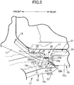
FIG. 3 is an operation explanatory view when involved in a frontal collision (first embodiment). -
FIG. 4 is a view corresponding toFIG. 2 (second embodiment). - In the following description reference numbers corresponding to components of exemplary embodiments are included only for ease of understanding, but the applicant's claims are not limited to the exemplary embodiments or to specific components of the exemplary embodiments.
- A first embodiment of the present invention is explained below by reference to
FIG. 1 to FIG. 3 . - As shown in
FIG. 1 andFIG. 2 , a vehicle body front part of an electric vehicle includes a dash panel lower 12 rising upward from the front end of avehicle body floor 11, and a rectangular frame-shapedfront bulkhead 14 is connected to front ends of a pair of left and rightfront side frames 13 extending forward from a front part of thevehicle body floor 11 and a lower part of the dash panel lower 12. Afront cross member 15 extending in the vehicle width direction is provided on a lower face of the front part of thevehicle body floor 11, a pair of left andright support members 16 extending downward are provided on front parts of the left and rightfront side frames 13, and afront sub frame 17 is suspended on a lower face of thefront cross member 15 and the lower ends of the left andright support members 16, thefront subframe 17 supporting a steering device, a suspension system of a front wheel, a compressor for air conditioning, etc. - The
front subframe 17 includes a pair of left and rightlongitudinal frames 18 extending in the fore-and-aft direction, across member 19 providing a link in the vehicle width direction between middle parts in the fore-and-aft direction of the left and rightlongitudinal frames 18, and anX-shaped reinforcing member 20 providing a link between the left and rightlongitudinal frames 18 to the rear of thecross member 19. Rear parts of the left and rightlongitudinal frames 18 of thefront subframe 17 are fastened by screwing twobolts 21, extending through the rear parts from bottom to top, into twonuts 22 provided in the interior of thefront cross member 15 and, furthermore, one ends of a pair of left andright stays 23 are fastened together by thebolts 21 and other ends of thestays 23 are fastened to the rear ends of the left and rightfront side frames 13 by twobolts 24. - A
battery pack 27 that includes acase 25 and acover 26 and that houses a battery for traveling is mounted on a lower face of thevehicle body floor 11. A pair of left and right batterypack support parts 28, which are reinforcing parts of thevehicle body floor 11, are downwardly projectingly provided so as to be in contact with a rear face of thefront cross member 15, and thecase 25 of thebattery pack 27 is suspendingly supported on the batterypack support parts 28 via a pair of left andright brackets 29. Eachbracket 29 includes anupper mounting portion 29a, alower mounting portion 29b, and aguide portion 29c providing a connection between theupper mounting portion 29a and thelower mounting portion 29b. - The
upper mounting portion 29a of eachbracket 29 is bent into an L shape and is fastened to abottom wall 28a of the battery pack supportpart 28 by abolt 30 extending through an upper part of theupper mounting portion 29a from bottom to top. Thelower mounting portion 29b of thebracket 29 extends rearward from the lower end of theguide portion 29c and is welded to abottom wall 25a of thecase 25 of thebattery pack 27. Theguide portion 29c of thebracket 29 is inclined upward to the front in going from thelower mounting portion 29b toward theupper mounting portion 29a, and theupper mounting portion 29a, ahead portion 30a of thebolt 30, and thelower mounting portion 29b are positioned to the rear with respect to an imaginary inclined line L that is an extension of theguide portion 29c in the fore-and-aft direction. Aguide wall 28b extending so as to be inclined upward to the front from thebottom wall 28a of the batterypack support part 28 is also positioned on the imaginary inclined line L. - On the other hand, each
longitudinal frame 18 of thefront subframe 17 is a hollow closed section member formed by joining anupper member 18a and alower member 18b via an outer peripheral flange, and a guide wall 18c parallel to the imaginary inclined line L is formed at the rear end of theupper member 18a facing the front of theguide wall 28b of the battery pack supportpart 28 and theguide portion 29c of thebracket 29. Ahigh voltage cable 32 is led out from ahigh voltage terminal 31 provided on afront wall 25b of thecase 25 of thebattery pack 27 toward a junction board (not illustrated) disposed above thefront side frames 13. - As is clear from
FIG. 2 , a dimension W1 in the vehicle width direction of thebracket 29 is smaller than a dimension W2 in the vehicle width direction of a rear end part of thelongitudinal frame 18, but a center C2 in the vehicle width direction of the rear end part of thelongitudinal frame 18 is offset outward in the vehicle width direction with respect to a center C1 in the vehicle width direction of thebracket 29. - The operation of the embodiment of the present invention having the above arrangement is now explained.
- When the vehicle is involved in a frontal collision and the
front subframe 17 moves rearward with respect to thefront side frames 13, the guide walls 18c at the rear ends of the left and rightlongitudinal frames 18 of thefront subframe 17 abut against theguide walls 28b of the batterypack support parts 28 and theguide portions 29c of thebrackets 29. Since the guide walls 18c of thefront subframe 17 are inclined downward from the upper front to the rear along the imaginary inclined line L, and theguide walls 28b of the batterypack support parts 28 and theguide portions 29c of thebrackets 29 are also inclined downward from the upper front to the rear along the imaginary inclined line L, as shown inFIG. 3 the rear end part of thefront subframe 17 slips downward along the imaginary inclined line L, the batterypack support parts 28 are broken, and thebolts 21 drop off. - As a result, the
front subframe 17 moves rearward while crumpling in the fore-and-aft direction and in the end stage of the collision the rear end part of thefront subframe 17 drops downward without interfering with the front end part of thebattery pack 27; not only is it possible to prevent thebattery pack 27 from being damaged due to collision with thefront subframe 17, but it is also possible to ensure the crash stroke of the vehicle body front part due to rearward movement of thefront subframe 17, thus enhancing the effect in absorbing collision energy. As described above, since the abutment relationship with the guide walls 18c of thelongitudinal frames 18 of thefront subframe 17 can be adjusted merely utilizing thebrackets 29 for fixing thebattery pack 27 to the vehicle body and changing the angle of inclination or the position of thebrackets 29 without subjecting the shape itself of thebattery pack 27 to a change in design, the cost is very low. - Moreover, since the center C2 in the vehicle width direction of the rear end parts of the
longitudinal frames 18 is offset outward in the vehicle width direction with respect to the center C1 in the vehicle width direction of thebrackets 29, even when the vehicle is involved in an oblique collision from the direction of arrow A ofFIG. 2 and the rear end parts of thelongitudinal frames 18 of thefront subframe 17 move obliquely rearward and inward in the vehicle width direction, it is possible to reliably make the rear end parts of thelongitudinal frames 18 abut against thebrackets 29. - Furthermore, although the front parts of the
brackets 29 are fixed to the batterypack support parts 28 by thebolts 30, since theupper mounting portions 29a of thebrackets 29 are bent rearward so that thehead portions 30a of thebolts 30 are positioned rearwardly of the imaginary inclined line L, the rear end part of thefront subframe 17, which moves rearward due to a frontal collision, does not interfere with thehead portions 30a of thebolts 30, thefront subframe 17 moves smoothly rearward, and thebrackets 29 can reliably drop off. - Moreover, since the
high voltage terminal 31 of thebattery pack 27 is positioned between the twobrackets 29 adjacent to each other in the vehicle width direction, thehigh voltage terminal 31 of thebattery pack 27 can be protected by the twobrackets 29 from an impact from the outside in the vehicle width direction. - A second embodiment of the present invention is now explained by reference to
FIG. 4 . - In the first embodiment, the dimension W2 in the vehicle width direction of the rear end parts of the
longitudinal frames 18 of thefront subframe 17 is set larger than the dimension W1 in the vehicle width direction of thebrackets 29; in the second embodiment the dimension W1 in the vehicle width direction of thebrackets 29 is set larger than the dimension W2 in the vehicle width direction of the rear end parts of thelongitudinal frames 18 of thefront subframe 17. This enables the rear end parts of thelongitudinal frames 18 of thefront subframe 17 to be more reliably abutted against thebrackets 29 even when thefront subframe 17 moves rearward in various directions due to a frontal collision. - Embodiments of the present invention are explained above, but the present invention may be modified in a variety of ways as long as the modifications do not depart from the gist of the present invention.
- For example, in the embodiments the guide walls 18c at the rear end of the
longitudinal frames 18 of thefront subframe 17 can abut against theguide walls 28b of the batterypack support parts 28 and theguide portions 29c of thebrackets 29, but theguide walls 28b of the batterypack support parts 28 are not always necessary and can be omitted. - Furthermore, in the embodiments the guide walls 18c are provided on the rear end parts of the
longitudinal frames 18 of thefront subframe 17, but the guide walls 18c are not always necessary as long as the rear end parts of thelongitudinal frames 18 can abut against theguide portions 29c of thebrackets 29. - Moreover, the vehicle body frame of the present invention is not limited to the
longitudinal frames 18 of thefront subframe 17 of the embodiments. - In a vehicle body front structure for an electric vehicle, including a battery pack mounted beneath a vehicle body floor, a bracket and a rear end part of a vehicle body frame are each inclined downward from an upper front to a rear. When viewed in a fore-and-aft direction, at least part of the bracket overlaps the rear end part. Therefore, the rear end part, moving rearward due to frontal collision, abuts against the bracket, and the frame slips and drops downward from the upper front to the lower rear along the bracket, thus preventing any decrease in crash stroke of the frame due to interference with the battery pack at the end stage of collision. Since abutment relationship with the rear end part can be adjusted merely changing angle of inclination or position of the bracket, the cost is very low.
Claims (5)
- A vehicle body front structure for an electric vehicle, comprising
a battery pack (27) mounted beneath a vehicle body floor (11),
a bracket (29) having a rear part and a front part thereof, the rear part being fixed to the battery pack (27) and the front part being fixed to the vehicle body floor (11), and
a vehicle body frame (18) disposed in a fore-and-aft direction in front of the vehicle body floor (11),
wherein a rear end part of the vehicle body frame (18) is inclined downward from an upper front to a rear,
the bracket (29) is inclined downward from the upper front to the rear, and
when viewed in the fore-and-aft direction, at least part of the bracket (29) overlaps the rear end part of the vehicle body frame (18). - The vehicle body front structure for an electric vehicle according to Claim 1, wherein a center (C2) in a vehicle width direction of the rear end part of the vehicle body frame (18) is offset outside in the vehicle width direction with respect to a center (C1) in the vehicle width direction of the bracket (29).
- The vehicle body front structure for an electric vehicle according to Claim 1, wherein a dimension (W1) in the vehicle width direction of the bracket (29) is larger than a dimension (W2) in the vehicle width direction of the rear end part of the vehicle body frame (18).
- The vehicle body front structure for an electric vehicle according to any one of Claim 1 to Claim 3, wherein
there are a plurality of vehicle body frames (18) as said vehicle body frame (18) and a plurality of brackets (29) as said bracket (29), and
a high voltage terminal (31) of the battery pack (27) is positioned between two of the brackets (29) that are adjacent to each other in the vehicle width direction. - The vehicle body front structure for an electric vehicle according to any one of Claim 1 to Claim 4, wherein
the front part of the bracket (29) is fixed to the vehicle body floor (11) by a bolt (30) and bent rearward so that a head portion (30a) of the bolt (30) is positioned rearwardly of an imaginary inclined line (L) of the bracket (29).
Applications Claiming Priority (1)
| Application Number | Priority Date | Filing Date | Title |
|---|---|---|---|
| JP2018081188A JP6669803B2 (en) | 2018-04-20 | 2018-04-20 | Front structure of electric vehicle |
Publications (2)
| Publication Number | Publication Date |
|---|---|
| EP3556591A1 true EP3556591A1 (en) | 2019-10-23 |
| EP3556591B1 EP3556591B1 (en) | 2020-12-23 |
Family
ID=66217944
Family Applications (1)
| Application Number | Title | Priority Date | Filing Date |
|---|---|---|---|
| EP19169849.7A Active EP3556591B1 (en) | 2018-04-20 | 2019-04-17 | Vehicle body front structure for electric vehicle |
Country Status (4)
| Country | Link |
|---|---|
| US (1) | US11173776B2 (en) |
| EP (1) | EP3556591B1 (en) |
| JP (1) | JP6669803B2 (en) |
| CN (1) | CN110395099B (en) |
Cited By (1)
| Publication number | Priority date | Publication date | Assignee | Title |
|---|---|---|---|---|
| WO2024160441A1 (en) * | 2023-02-02 | 2024-08-08 | Volkswagen Aktiengesellschaft | Method for mounting a battery unit, vehicle and production method |
Families Citing this family (26)
| Publication number | Priority date | Publication date | Assignee | Title |
|---|---|---|---|---|
| JP6237863B1 (en) * | 2016-11-17 | 2017-11-29 | マツダ株式会社 | Front subframe structure |
| US11027782B2 (en) * | 2018-07-03 | 2021-06-08 | Toyota Jidosha Kabushiki Kaisha | Vehicle front-part structure |
| JP7363159B2 (en) * | 2019-07-24 | 2023-10-18 | マツダ株式会社 | Front suspension subframe structure |
| JP7256147B2 (en) * | 2020-05-11 | 2023-04-11 | トヨタ自動車株式会社 | electric vehicle |
| JP7272998B2 (en) * | 2020-06-02 | 2023-05-12 | トヨタ自動車株式会社 | electric vehicle |
| JP7456302B2 (en) * | 2020-06-16 | 2024-03-27 | スズキ株式会社 | Vehicle battery protection structure |
| DE102020123289B3 (en) * | 2020-09-07 | 2021-12-09 | Bayerische Motoren Werke Aktiengesellschaft | Energy storage floor assembly for an electrically powered passenger car |
| US11745573B2 (en) | 2020-10-22 | 2023-09-05 | Ford Global Technologies, Llc | Integrated frame and battery pack structure for electric vehicles |
| DE102020128605A1 (en) * | 2020-10-30 | 2022-05-05 | Bayerische Motoren Werke Aktiengesellschaft | Energy storage floor assembly for an electrically driven motor vehicle |
| JP7369681B2 (en) * | 2020-11-11 | 2023-10-26 | 本田技研工業株式会社 | Vehicles equipped with battery packs |
| KR20220099307A (en) * | 2021-01-06 | 2022-07-13 | 현대자동차주식회사 | Mounting structure for power electric module and vehicle body provided with the same |
| CN114954630B (en) * | 2021-02-24 | 2024-11-15 | 本田技研工业株式会社 | Front structure of the vehicle |
| JP7397020B2 (en) * | 2021-03-15 | 2023-12-12 | トヨタ自動車株式会社 | vehicle |
| JP7559645B2 (en) * | 2021-03-26 | 2024-10-02 | マツダ株式会社 | Electric vehicle undercarriage |
| JP7468434B2 (en) * | 2021-03-30 | 2024-04-16 | マツダ株式会社 | Body structure |
| JP7676964B2 (en) * | 2021-06-01 | 2025-05-15 | マツダ株式会社 | Body structure |
| JP2023002363A (en) * | 2021-06-22 | 2023-01-10 | トヨタ自動車株式会社 | vehicle front structure |
| US11897543B2 (en) * | 2021-07-26 | 2024-02-13 | Rivian Ip Holdings, Llc | Vehicle chassis shear plate |
| JP7677029B2 (en) * | 2021-07-26 | 2025-05-15 | マツダ株式会社 | Hybrid vehicle undercarriage |
| KR20230096453A (en) * | 2021-12-23 | 2023-06-30 | 현대자동차주식회사 | Mounting structure of sub-frame of vehicle for avoiding collision between battery and sub-frame |
| US12565270B2 (en) * | 2022-02-24 | 2026-03-03 | Mazda Motor Corporation | Vehicle-body front structure including a reinforcement structure that couples a motor arrangement portion and a cross structure together |
| US20230264557A1 (en) * | 2022-02-24 | 2023-08-24 | Mazda Motor Corporation | Vehicle-body front structure with side frame support |
| JP7764781B2 (en) * | 2022-02-24 | 2025-11-06 | マツダ株式会社 | Body structure |
| JP7796570B2 (en) * | 2022-03-24 | 2026-01-09 | 本田技研工業株式会社 | Vehicle body device protection structure |
| JP2024024758A (en) * | 2022-08-10 | 2024-02-26 | トヨタ自動車株式会社 | Vehicle front structure |
| FR3166112A1 (en) * | 2024-09-10 | 2026-03-13 | Renault Sas | Arrangement for motor vehicle. |
Citations (2)
| Publication number | Priority date | Publication date | Assignee | Title |
|---|---|---|---|---|
| JPH07117725A (en) | 1993-10-22 | 1995-05-09 | Nissan Motor Co Ltd | Electric vehicle body front structure |
| US20130119706A1 (en) * | 2011-11-14 | 2013-05-16 | Honda Motor Co., Ltd. | Power supply system for electric vehicle |
Family Cites Families (22)
| Publication number | Priority date | Publication date | Assignee | Title |
|---|---|---|---|---|
| US5555950A (en) * | 1992-03-04 | 1996-09-17 | Toyota Jidosha Kabushiki Kaisha | Body structure for electric vehicle |
| US5501289A (en) * | 1993-01-22 | 1996-03-26 | Nissan Motor Co., Ltd. | Floor structure of electric vehicle |
| US5605353A (en) * | 1995-08-09 | 1997-02-25 | General Motors Corporation | Vehicle chassis with energy management |
| US6598691B2 (en) * | 1997-12-18 | 2003-07-29 | Honda Giken Kogyo Kabushiki Kaisha | Electric vehicle |
| JP2003261061A (en) * | 2002-03-08 | 2003-09-16 | Nissan Motor Co Ltd | Car front body structure |
| JP4325351B2 (en) * | 2003-10-08 | 2009-09-02 | 三菱自動車工業株式会社 | Vehicle chassis mounting structure |
| WO2007037113A1 (en) * | 2005-09-27 | 2007-04-05 | Autoliv Development Ab | Impact reducing structure of vehicle |
| JP4957492B2 (en) * | 2007-09-28 | 2012-06-20 | 三菱自動車工業株式会社 | Electric vehicle battery unit cooling duct structure |
| DE102009042513A1 (en) * | 2009-09-22 | 2011-03-24 | GM Global Technology Operations, Inc., Detroit | Vehicle with energy storage area |
| JP2012045995A (en) | 2010-08-25 | 2012-03-08 | Nissan Motor Co Ltd | Vehicle body structure |
| JP5528988B2 (en) * | 2010-11-16 | 2014-06-25 | 本田技研工業株式会社 | Support structure for vehicle battery unit |
| US9022152B2 (en) * | 2010-12-24 | 2015-05-05 | Honda Motor Co., Ltd. | Automobile body structure |
| DE102011051698A1 (en) | 2011-07-08 | 2013-01-10 | Thyssenkrupp Steel Europe Ag | Floor structure for a vehicle |
| JP5468594B2 (en) * | 2011-11-14 | 2014-04-09 | 本田技研工業株式会社 | Electric vehicle power supply device |
| EP3106373B1 (en) * | 2012-02-13 | 2018-09-19 | Honda Motor Co., Ltd. | Vehicle body bottom structure |
| US8646790B2 (en) * | 2012-04-12 | 2014-02-11 | Toyota Motor Engineering & Manufacturing North America, Inc. | Sub-frame intrusion control by ramping during frontal impact for electric vehicle battery protection |
| WO2014038346A1 (en) * | 2012-09-04 | 2014-03-13 | 日産自動車株式会社 | Vehicle body structure of electric vehicle |
| JP5776677B2 (en) * | 2012-12-19 | 2015-09-09 | トヨタ自動車株式会社 | Body front structure |
| JP2013154880A (en) * | 2013-04-12 | 2013-08-15 | Mitsubishi Motors Corp | Mounting structure of vehicle battery unit |
| JP5790714B2 (en) * | 2013-06-20 | 2015-10-07 | トヨタ自動車株式会社 | Vehicle lower structure |
| WO2015156052A1 (en) * | 2014-04-11 | 2015-10-15 | 本田技研工業株式会社 | Automobile vehicle-body structure |
| JP6314757B2 (en) * | 2014-09-04 | 2018-04-25 | 日産自動車株式会社 | Rear structure of electric vehicle body |
-
2018
- 2018-04-20 JP JP2018081188A patent/JP6669803B2/en active Active
-
2019
- 2019-04-17 CN CN201910310774.7A patent/CN110395099B/en active Active
- 2019-04-17 EP EP19169849.7A patent/EP3556591B1/en active Active
- 2019-04-17 US US16/386,436 patent/US11173776B2/en active Active
Patent Citations (2)
| Publication number | Priority date | Publication date | Assignee | Title |
|---|---|---|---|---|
| JPH07117725A (en) | 1993-10-22 | 1995-05-09 | Nissan Motor Co Ltd | Electric vehicle body front structure |
| US20130119706A1 (en) * | 2011-11-14 | 2013-05-16 | Honda Motor Co., Ltd. | Power supply system for electric vehicle |
Cited By (1)
| Publication number | Priority date | Publication date | Assignee | Title |
|---|---|---|---|---|
| WO2024160441A1 (en) * | 2023-02-02 | 2024-08-08 | Volkswagen Aktiengesellschaft | Method for mounting a battery unit, vehicle and production method |
Also Published As
| Publication number | Publication date |
|---|---|
| US20190322164A1 (en) | 2019-10-24 |
| US11173776B2 (en) | 2021-11-16 |
| CN110395099A (en) | 2019-11-01 |
| CN110395099B (en) | 2022-12-23 |
| EP3556591B1 (en) | 2020-12-23 |
| JP6669803B2 (en) | 2020-03-18 |
| JP2019188899A (en) | 2019-10-31 |
Similar Documents
| Publication | Publication Date | Title |
|---|---|---|
| EP3556591B1 (en) | Vehicle body front structure for electric vehicle | |
| CN109421805B (en) | Vehicle body structure of electric vehicle | |
| US9248865B2 (en) | Vehicle body front structure | |
| US10618489B2 (en) | Utility vehicle | |
| JP6511078B2 (en) | Electric car floor structure | |
| US10604189B2 (en) | Vehicle body front part structure | |
| US10717469B2 (en) | Vehicle body front part structure | |
| KR101518925B1 (en) | Front vehicle body reinforcing structure | |
| US20190232911A1 (en) | Utility vehicle | |
| JP5942810B2 (en) | Front subframe of automobile and its supporting structure | |
| CN110901362A (en) | vehicle substructure | |
| CN115503835A (en) | Vehicle Front Structure | |
| JP5942811B2 (en) | Undercarriage of the vehicle | |
| CN108928395A (en) | Car body fore part arrangement | |
| CN107021138A (en) | The body structure of automobile and the manufacture method of automobile | |
| JP5076718B2 (en) | Front body structure of automobile | |
| KR102394581B1 (en) | Front vehicle body reinforcing structure | |
| CN109664948B (en) | Vehicle front structure | |
| JP2009035106A (en) | Front vehicle body structure of automobile | |
| US11667332B2 (en) | Subframe structure | |
| KR101484221B1 (en) | Rear shock absorber mounting structure for vehicle | |
| US11787474B2 (en) | Vehicle suspension tower structure | |
| JP2015202707A (en) | Front structure of cab-over type vehicle | |
| US9493131B2 (en) | Structure for front of vehicle body | |
| WO2023175843A1 (en) | Vehicle body front part structure |
Legal Events
| Date | Code | Title | Description |
|---|---|---|---|
| PUAI | Public reference made under article 153(3) epc to a published international application that has entered the european phase |
Free format text: ORIGINAL CODE: 0009012 |
|
| STAA | Information on the status of an ep patent application or granted ep patent |
Free format text: STATUS: REQUEST FOR EXAMINATION WAS MADE |
|
| 17P | Request for examination filed |
Effective date: 20190417 |
|
| AK | Designated contracting states |
Kind code of ref document: A1 Designated state(s): AL AT BE BG CH CY CZ DE DK EE ES FI FR GB GR HR HU IE IS IT LI LT LU LV MC MK MT NL NO PL PT RO RS SE SI SK SM TR |
|
| AX | Request for extension of the european patent |
Extension state: BA ME |
|
| GRAP | Despatch of communication of intention to grant a patent |
Free format text: ORIGINAL CODE: EPIDOSNIGR1 |
|
| STAA | Information on the status of an ep patent application or granted ep patent |
Free format text: STATUS: GRANT OF PATENT IS INTENDED |
|
| RIC1 | Information provided on ipc code assigned before grant |
Ipc: B60K 1/04 20190101AFI20200720BHEP |
|
| INTG | Intention to grant announced |
Effective date: 20200814 |
|
| GRAS | Grant fee paid |
Free format text: ORIGINAL CODE: EPIDOSNIGR3 |
|
| GRAA | (expected) grant |
Free format text: ORIGINAL CODE: 0009210 |
|
| STAA | Information on the status of an ep patent application or granted ep patent |
Free format text: STATUS: THE PATENT HAS BEEN GRANTED |
|
| AK | Designated contracting states |
Kind code of ref document: B1 Designated state(s): AL AT BE BG CH CY CZ DE DK EE ES FI FR GB GR HR HU IE IS IT LI LT LU LV MC MK MT NL NO PL PT RO RS SE SI SK SM TR |
|
| REG | Reference to a national code |
Ref country code: GB Ref legal event code: FG4D |
|
| REG | Reference to a national code |
Ref country code: DE Ref legal event code: R096 Ref document number: 602019001839 Country of ref document: DE |
|
| REG | Reference to a national code |
Ref country code: AT Ref legal event code: REF Ref document number: 1347383 Country of ref document: AT Kind code of ref document: T Effective date: 20210115 |
|
| REG | Reference to a national code |
Ref country code: IE Ref legal event code: FG4D |
|
| PG25 | Lapsed in a contracting state [announced via postgrant information from national office to epo] |
Ref country code: FI Free format text: LAPSE BECAUSE OF FAILURE TO SUBMIT A TRANSLATION OF THE DESCRIPTION OR TO PAY THE FEE WITHIN THE PRESCRIBED TIME-LIMIT Effective date: 20201223 Ref country code: RS Free format text: LAPSE BECAUSE OF FAILURE TO SUBMIT A TRANSLATION OF THE DESCRIPTION OR TO PAY THE FEE WITHIN THE PRESCRIBED TIME-LIMIT Effective date: 20201223 Ref country code: NO Free format text: LAPSE BECAUSE OF FAILURE TO SUBMIT A TRANSLATION OF THE DESCRIPTION OR TO PAY THE FEE WITHIN THE PRESCRIBED TIME-LIMIT Effective date: 20210323 Ref country code: GR Free format text: LAPSE BECAUSE OF FAILURE TO SUBMIT A TRANSLATION OF THE DESCRIPTION OR TO PAY THE FEE WITHIN THE PRESCRIBED TIME-LIMIT Effective date: 20210324 |
|
| REG | Reference to a national code |
Ref country code: AT Ref legal event code: MK05 Ref document number: 1347383 Country of ref document: AT Kind code of ref document: T Effective date: 20201223 |
|
| REG | Reference to a national code |
Ref country code: NL Ref legal event code: MP Effective date: 20201223 |
|
| PG25 | Lapsed in a contracting state [announced via postgrant information from national office to epo] |
Ref country code: LV Free format text: LAPSE BECAUSE OF FAILURE TO SUBMIT A TRANSLATION OF THE DESCRIPTION OR TO PAY THE FEE WITHIN THE PRESCRIBED TIME-LIMIT Effective date: 20201223 Ref country code: SE Free format text: LAPSE BECAUSE OF FAILURE TO SUBMIT A TRANSLATION OF THE DESCRIPTION OR TO PAY THE FEE WITHIN THE PRESCRIBED TIME-LIMIT Effective date: 20201223 Ref country code: BG Free format text: LAPSE BECAUSE OF FAILURE TO SUBMIT A TRANSLATION OF THE DESCRIPTION OR TO PAY THE FEE WITHIN THE PRESCRIBED TIME-LIMIT Effective date: 20210323 |
|
| PG25 | Lapsed in a contracting state [announced via postgrant information from national office to epo] |
Ref country code: NL Free format text: LAPSE BECAUSE OF FAILURE TO SUBMIT A TRANSLATION OF THE DESCRIPTION OR TO PAY THE FEE WITHIN THE PRESCRIBED TIME-LIMIT Effective date: 20201223 Ref country code: HR Free format text: LAPSE BECAUSE OF FAILURE TO SUBMIT A TRANSLATION OF THE DESCRIPTION OR TO PAY THE FEE WITHIN THE PRESCRIBED TIME-LIMIT Effective date: 20201223 |
|
| REG | Reference to a national code |
Ref country code: LT Ref legal event code: MG9D |
|
| PG25 | Lapsed in a contracting state [announced via postgrant information from national office to epo] |
Ref country code: CZ Free format text: LAPSE BECAUSE OF FAILURE TO SUBMIT A TRANSLATION OF THE DESCRIPTION OR TO PAY THE FEE WITHIN THE PRESCRIBED TIME-LIMIT Effective date: 20201223 Ref country code: EE Free format text: LAPSE BECAUSE OF FAILURE TO SUBMIT A TRANSLATION OF THE DESCRIPTION OR TO PAY THE FEE WITHIN THE PRESCRIBED TIME-LIMIT Effective date: 20201223 Ref country code: SM Free format text: LAPSE BECAUSE OF FAILURE TO SUBMIT A TRANSLATION OF THE DESCRIPTION OR TO PAY THE FEE WITHIN THE PRESCRIBED TIME-LIMIT Effective date: 20201223 Ref country code: SK Free format text: LAPSE BECAUSE OF FAILURE TO SUBMIT A TRANSLATION OF THE DESCRIPTION OR TO PAY THE FEE WITHIN THE PRESCRIBED TIME-LIMIT Effective date: 20201223 Ref country code: PT Free format text: LAPSE BECAUSE OF FAILURE TO SUBMIT A TRANSLATION OF THE DESCRIPTION OR TO PAY THE FEE WITHIN THE PRESCRIBED TIME-LIMIT Effective date: 20210423 Ref country code: RO Free format text: LAPSE BECAUSE OF FAILURE TO SUBMIT A TRANSLATION OF THE DESCRIPTION OR TO PAY THE FEE WITHIN THE PRESCRIBED TIME-LIMIT Effective date: 20201223 Ref country code: LT Free format text: LAPSE BECAUSE OF FAILURE TO SUBMIT A TRANSLATION OF THE DESCRIPTION OR TO PAY THE FEE WITHIN THE PRESCRIBED TIME-LIMIT Effective date: 20201223 |
|
| REG | Reference to a national code |
Ref country code: DE Ref legal event code: R084 Ref document number: 602019001839 Country of ref document: DE |
|
| PG25 | Lapsed in a contracting state [announced via postgrant information from national office to epo] |
Ref country code: AT Free format text: LAPSE BECAUSE OF FAILURE TO SUBMIT A TRANSLATION OF THE DESCRIPTION OR TO PAY THE FEE WITHIN THE PRESCRIBED TIME-LIMIT Effective date: 20201223 Ref country code: PL Free format text: LAPSE BECAUSE OF FAILURE TO SUBMIT A TRANSLATION OF THE DESCRIPTION OR TO PAY THE FEE WITHIN THE PRESCRIBED TIME-LIMIT Effective date: 20201223 |
|
| REG | Reference to a national code |
Ref country code: DE Ref legal event code: R097 Ref document number: 602019001839 Country of ref document: DE |
|
| PG25 | Lapsed in a contracting state [announced via postgrant information from national office to epo] |
Ref country code: IS Free format text: LAPSE BECAUSE OF FAILURE TO SUBMIT A TRANSLATION OF THE DESCRIPTION OR TO PAY THE FEE WITHIN THE PRESCRIBED TIME-LIMIT Effective date: 20210423 |
|
| PG25 | Lapsed in a contracting state [announced via postgrant information from national office to epo] |
Ref country code: AL Free format text: LAPSE BECAUSE OF FAILURE TO SUBMIT A TRANSLATION OF THE DESCRIPTION OR TO PAY THE FEE WITHIN THE PRESCRIBED TIME-LIMIT Effective date: 20201223 Ref country code: IT Free format text: LAPSE BECAUSE OF FAILURE TO SUBMIT A TRANSLATION OF THE DESCRIPTION OR TO PAY THE FEE WITHIN THE PRESCRIBED TIME-LIMIT Effective date: 20201223 |
|
| PLBE | No opposition filed within time limit |
Free format text: ORIGINAL CODE: 0009261 |
|
| STAA | Information on the status of an ep patent application or granted ep patent |
Free format text: STATUS: NO OPPOSITION FILED WITHIN TIME LIMIT |
|
| PG25 | Lapsed in a contracting state [announced via postgrant information from national office to epo] |
Ref country code: MC Free format text: LAPSE BECAUSE OF FAILURE TO SUBMIT A TRANSLATION OF THE DESCRIPTION OR TO PAY THE FEE WITHIN THE PRESCRIBED TIME-LIMIT Effective date: 20201223 Ref country code: DK Free format text: LAPSE BECAUSE OF FAILURE TO SUBMIT A TRANSLATION OF THE DESCRIPTION OR TO PAY THE FEE WITHIN THE PRESCRIBED TIME-LIMIT Effective date: 20201223 |
|
| 26N | No opposition filed |
Effective date: 20210924 |
|
| PG25 | Lapsed in a contracting state [announced via postgrant information from national office to epo] |
Ref country code: LU Free format text: LAPSE BECAUSE OF NON-PAYMENT OF DUE FEES Effective date: 20210417 |
|
| REG | Reference to a national code |
Ref country code: BE Ref legal event code: MM Effective date: 20210430 |
|
| PG25 | Lapsed in a contracting state [announced via postgrant information from national office to epo] |
Ref country code: FR Free format text: LAPSE BECAUSE OF NON-PAYMENT OF DUE FEES Effective date: 20210430 Ref country code: ES Free format text: LAPSE BECAUSE OF FAILURE TO SUBMIT A TRANSLATION OF THE DESCRIPTION OR TO PAY THE FEE WITHIN THE PRESCRIBED TIME-LIMIT Effective date: 20201223 |
|
| PG25 | Lapsed in a contracting state [announced via postgrant information from national office to epo] |
Ref country code: SI Free format text: LAPSE BECAUSE OF FAILURE TO SUBMIT A TRANSLATION OF THE DESCRIPTION OR TO PAY THE FEE WITHIN THE PRESCRIBED TIME-LIMIT Effective date: 20201223 |
|
| PG25 | Lapsed in a contracting state [announced via postgrant information from national office to epo] |
Ref country code: IE Free format text: LAPSE BECAUSE OF NON-PAYMENT OF DUE FEES Effective date: 20210417 |
|
| PG25 | Lapsed in a contracting state [announced via postgrant information from national office to epo] |
Ref country code: IS Free format text: LAPSE BECAUSE OF FAILURE TO SUBMIT A TRANSLATION OF THE DESCRIPTION OR TO PAY THE FEE WITHIN THE PRESCRIBED TIME-LIMIT Effective date: 20210423 |
|
| PG25 | Lapsed in a contracting state [announced via postgrant information from national office to epo] |
Ref country code: BE Free format text: LAPSE BECAUSE OF NON-PAYMENT OF DUE FEES Effective date: 20210430 |
|
| REG | Reference to a national code |
Ref country code: CH Ref legal event code: PL |
|
| PG25 | Lapsed in a contracting state [announced via postgrant information from national office to epo] |
Ref country code: LI Free format text: LAPSE BECAUSE OF NON-PAYMENT OF DUE FEES Effective date: 20220430 Ref country code: CH Free format text: LAPSE BECAUSE OF NON-PAYMENT OF DUE FEES Effective date: 20220430 |
|
| PG25 | Lapsed in a contracting state [announced via postgrant information from national office to epo] |
Ref country code: CY Free format text: LAPSE BECAUSE OF FAILURE TO SUBMIT A TRANSLATION OF THE DESCRIPTION OR TO PAY THE FEE WITHIN THE PRESCRIBED TIME-LIMIT Effective date: 20201223 |
|
| PG25 | Lapsed in a contracting state [announced via postgrant information from national office to epo] |
Ref country code: HU Free format text: LAPSE BECAUSE OF FAILURE TO SUBMIT A TRANSLATION OF THE DESCRIPTION OR TO PAY THE FEE WITHIN THE PRESCRIBED TIME-LIMIT; INVALID AB INITIO Effective date: 20190417 |
|
| GBPC | Gb: european patent ceased through non-payment of renewal fee |
Effective date: 20230417 |
|
| PG25 | Lapsed in a contracting state [announced via postgrant information from national office to epo] |
Ref country code: GB Free format text: LAPSE BECAUSE OF NON-PAYMENT OF DUE FEES Effective date: 20230417 |
|
| PG25 | Lapsed in a contracting state [announced via postgrant information from national office to epo] |
Ref country code: GB Free format text: LAPSE BECAUSE OF NON-PAYMENT OF DUE FEES Effective date: 20230417 |
|
| PG25 | Lapsed in a contracting state [announced via postgrant information from national office to epo] |
Ref country code: MK Free format text: LAPSE BECAUSE OF FAILURE TO SUBMIT A TRANSLATION OF THE DESCRIPTION OR TO PAY THE FEE WITHIN THE PRESCRIBED TIME-LIMIT Effective date: 20201223 |
|
| PG25 | Lapsed in a contracting state [announced via postgrant information from national office to epo] |
Ref country code: TR Free format text: LAPSE BECAUSE OF FAILURE TO SUBMIT A TRANSLATION OF THE DESCRIPTION OR TO PAY THE FEE WITHIN THE PRESCRIBED TIME-LIMIT Effective date: 20201223 |
|
| PG25 | Lapsed in a contracting state [announced via postgrant information from national office to epo] |
Ref country code: MT Free format text: LAPSE BECAUSE OF FAILURE TO SUBMIT A TRANSLATION OF THE DESCRIPTION OR TO PAY THE FEE WITHIN THE PRESCRIBED TIME-LIMIT Effective date: 20201223 |
|
| PGFP | Annual fee paid to national office [announced via postgrant information from national office to epo] |
Ref country code: DE Payment date: 20250319 Year of fee payment: 7 |