EP3556538B1 - Verfahren zum herstellen einer injektionsvorrichtung mit bypasskanal und werkzeug hierfür - Google Patents
Verfahren zum herstellen einer injektionsvorrichtung mit bypasskanal und werkzeug hierfür Download PDFInfo
- Publication number
- EP3556538B1 EP3556538B1 EP19163351.0A EP19163351A EP3556538B1 EP 3556538 B1 EP3556538 B1 EP 3556538B1 EP 19163351 A EP19163351 A EP 19163351A EP 3556538 B1 EP3556538 B1 EP 3556538B1
- Authority
- EP
- European Patent Office
- Prior art keywords
- preform
- tool
- bypass channel
- cylindrical portion
- punch
- Prior art date
- Legal status (The legal status is an assumption and is not a legal conclusion. Google has not performed a legal analysis and makes no representation as to the accuracy of the status listed.)
- Active
Links
Images
Classifications
-
- B—PERFORMING OPERATIONS; TRANSPORTING
- B29—WORKING OF PLASTICS; WORKING OF SUBSTANCES IN A PLASTIC STATE IN GENERAL
- B29C—SHAPING OR JOINING OF PLASTICS; SHAPING OF MATERIAL IN A PLASTIC STATE, NOT OTHERWISE PROVIDED FOR; AFTER-TREATMENT OF THE SHAPED PRODUCTS, e.g. REPAIRING
- B29C45/00—Injection moulding, i.e. forcing the required volume of moulding material through a nozzle into a closed mould; Apparatus therefor
- B29C45/14—Injection moulding, i.e. forcing the required volume of moulding material through a nozzle into a closed mould; Apparatus therefor incorporating preformed parts or layers, e.g. injection moulding around inserts or for coating articles
-
- B—PERFORMING OPERATIONS; TRANSPORTING
- B29—WORKING OF PLASTICS; WORKING OF SUBSTANCES IN A PLASTIC STATE IN GENERAL
- B29C—SHAPING OR JOINING OF PLASTICS; SHAPING OF MATERIAL IN A PLASTIC STATE, NOT OTHERWISE PROVIDED FOR; AFTER-TREATMENT OF THE SHAPED PRODUCTS, e.g. REPAIRING
- B29C55/00—Shaping by stretching, e.g. drawing through a die; Apparatus therefor
- B29C55/22—Shaping by stretching, e.g. drawing through a die; Apparatus therefor of tubes
- B29C55/24—Shaping by stretching, e.g. drawing through a die; Apparatus therefor of tubes radial
-
- A—HUMAN NECESSITIES
- A61—MEDICAL OR VETERINARY SCIENCE; HYGIENE
- A61M—DEVICES FOR INTRODUCING MEDIA INTO, OR ONTO, THE BODY; DEVICES FOR TRANSDUCING BODY MEDIA OR FOR TAKING MEDIA FROM THE BODY; DEVICES FOR PRODUCING OR ENDING SLEEP OR STUPOR
- A61M5/00—Devices for bringing media into the body in a subcutaneous, intra-vascular or intramuscular way; Accessories therefor, e.g. filling or cleaning devices, arm-rests
- A61M5/178—Syringes
- A61M5/31—Details
- A61M5/3129—Syringe barrels
-
- B—PERFORMING OPERATIONS; TRANSPORTING
- B29—WORKING OF PLASTICS; WORKING OF SUBSTANCES IN A PLASTIC STATE IN GENERAL
- B29C—SHAPING OR JOINING OF PLASTICS; SHAPING OF MATERIAL IN A PLASTIC STATE, NOT OTHERWISE PROVIDED FOR; AFTER-TREATMENT OF THE SHAPED PRODUCTS, e.g. REPAIRING
- B29C51/00—Shaping by thermoforming, i.e. shaping sheets or sheet like preforms after heating, e.g. shaping sheets in matched moulds or by deep-drawing; Apparatus therefor
- B29C51/10—Forming by pressure difference, e.g. vacuum
-
- B—PERFORMING OPERATIONS; TRANSPORTING
- B29—WORKING OF PLASTICS; WORKING OF SUBSTANCES IN A PLASTIC STATE IN GENERAL
- B29C—SHAPING OR JOINING OF PLASTICS; SHAPING OF MATERIAL IN A PLASTIC STATE, NOT OTHERWISE PROVIDED FOR; AFTER-TREATMENT OF THE SHAPED PRODUCTS, e.g. REPAIRING
- B29C67/00—Shaping techniques not covered by groups B29C39/00 - B29C65/00, B29C70/00 or B29C73/00
- B29C67/0014—Shaping techniques not covered by groups B29C39/00 - B29C65/00, B29C70/00 or B29C73/00 for shaping tubes or blown tubular films
- B29C67/0022—Shaping techniques not covered by groups B29C39/00 - B29C65/00, B29C70/00 or B29C73/00 for shaping tubes or blown tubular films using an internal mandrel
-
- B—PERFORMING OPERATIONS; TRANSPORTING
- B29—WORKING OF PLASTICS; WORKING OF SUBSTANCES IN A PLASTIC STATE IN GENERAL
- B29C—SHAPING OR JOINING OF PLASTICS; SHAPING OF MATERIAL IN A PLASTIC STATE, NOT OTHERWISE PROVIDED FOR; AFTER-TREATMENT OF THE SHAPED PRODUCTS, e.g. REPAIRING
- B29C67/00—Shaping techniques not covered by groups B29C39/00 - B29C65/00, B29C70/00 or B29C73/00
- B29C67/0048—Local deformation of formed objects
-
- A—HUMAN NECESSITIES
- A61—MEDICAL OR VETERINARY SCIENCE; HYGIENE
- A61M—DEVICES FOR INTRODUCING MEDIA INTO, OR ONTO, THE BODY; DEVICES FOR TRANSDUCING BODY MEDIA OR FOR TAKING MEDIA FROM THE BODY; DEVICES FOR PRODUCING OR ENDING SLEEP OR STUPOR
- A61M5/00—Devices for bringing media into the body in a subcutaneous, intra-vascular or intramuscular way; Accessories therefor, e.g. filling or cleaning devices, arm-rests
- A61M5/178—Syringes
- A61M5/31—Details
- A61M5/3129—Syringe barrels
- A61M2005/3132—Syringe barrels having flow passages for injection agents at the distal end of the barrel to bypass a sealing stopper after its displacement to this end due to internal pressure increase
-
- A—HUMAN NECESSITIES
- A61—MEDICAL OR VETERINARY SCIENCE; HYGIENE
- A61M—DEVICES FOR INTRODUCING MEDIA INTO, OR ONTO, THE BODY; DEVICES FOR TRANSDUCING BODY MEDIA OR FOR TAKING MEDIA FROM THE BODY; DEVICES FOR PRODUCING OR ENDING SLEEP OR STUPOR
- A61M2207/00—Methods of manufacture, assembly or production
- A61M2207/10—Device therefor
-
- B—PERFORMING OPERATIONS; TRANSPORTING
- B29—WORKING OF PLASTICS; WORKING OF SUBSTANCES IN A PLASTIC STATE IN GENERAL
- B29C—SHAPING OR JOINING OF PLASTICS; SHAPING OF MATERIAL IN A PLASTIC STATE, NOT OTHERWISE PROVIDED FOR; AFTER-TREATMENT OF THE SHAPED PRODUCTS, e.g. REPAIRING
- B29C2791/00—Shaping characteristics in general
- B29C2791/004—Shaping under special conditions
- B29C2791/006—Using vacuum
-
- B—PERFORMING OPERATIONS; TRANSPORTING
- B29—WORKING OF PLASTICS; WORKING OF SUBSTANCES IN A PLASTIC STATE IN GENERAL
- B29L—INDEXING SCHEME ASSOCIATED WITH SUBCLASS B29C, RELATING TO PARTICULAR ARTICLES
- B29L2031/00—Other particular articles
- B29L2031/753—Medical equipment; Accessories therefor
- B29L2031/7544—Injection needles, syringes
Definitions
- the invention relates to a method for producing an injection device with a bypass channel.
- the invention relates to a tool for the method for producing an injection device with a bypass channel.
- the German patent application DE 10 2007 014 281 A1 discloses a method for manufacturing a multi-chamber syringe with a bypass channel.
- a preform is first produced from a thermoformable plastic with a tubular section.
- the preform is surrounded by a die in the area in which the bypass channel is to be formed.
- the die has formed a depression in the area of the bypass channel.
- the preform is heated to a temperature above the softening range of the plastic.
- the tubular portion of the preform is positioned in the die and pressure is applied. Due to the pressure difference, the wall of the preform is pressed into the recesses of the die, so that the bypass channel is plastically formed.
- DE 10 2007 014 281 A1 also discloses a method and a tool for manufacturing an injection device with a bypass channel by means of a die.
- German patent application DE 29 25 858 discloses a folding core that can be used to form undercuts inside injection molded parts.
- the bypass channel in the injection syringe could also be formed with the folding core.
- the folded core is mechanically complex and would also lead to separating edges and particle formation during the injection molding process of the hypodermic syringe.
- Another way of forming the bypass channel in the injection syringe is to use inserts that form the bypass channel during the injection molding process.
- a second tool would be required for this, which leads to longer cycles in the production of hypodermic syringes. These longer cycles and the second tool consequently increase the parts cost for the hypodermic syringe equipped with the bypass port. Handling the inserts also leads to longer cycle times, higher costs and particle formation cannot be ruled out in the injection molding process.
- the bypass channel in the hypodermic syringe could also be produced using a two-component injection molding process.
- two-component injection molding has the disadvantage that it leads to higher tool costs and less tool occupancy. The tool itself is very complex and therefore vulnerable.
- two-component injection molding also leads to higher part prices.
- U.S. 3,932,093 A and FR 2 244 609 A1 disclose further methods and complex expander tools for producing an injection device.
- the invention is based on the object of creating a method for producing an injection device with a bypass channel which is easy and reliable to handle and reduces the costs per injection device produced.
- the invention is based on the object of creating a tool for producing an injection device with a bypass channel, with which the bypass channel can be formed in the injection device in a simple, reliable and cost-effective manner.
- the method according to the invention for producing an injection device with a bypass channel is characterized in that a preform is first placed in a tool.
- the preform partially rests with a cylindrical outer surface of a cylindrical section in the tool.
- a partial area of the cylindrical section is then heated.
- a stamp can be pushed into the cylindrical section essentially in the axial direction.
- the punch is in position to the heated portion, the punch is displaced in the radial direction onto a cylindrical inner surface of the cylindrical portion of the preform.
- the stamp is then pressed into the heated partial area of the cylindrical section and the bypass channel is thereby formed by plastic deformation of the heated partial area.
- the method according to the invention has the advantage that the bypass channel is formed by means of the die, e.g. after the injection molding process.
- the plunger By using the plunger, expensive operating resources can be saved and no particles or separations occur in the body of the injection syringe, which would lead to contamination of the finished product.
- the partial area of the cylindrical section is heated with a heat source, or heated.
- the heat source is used to bring the material of the partial area to such a temperature that the material of the preform can be plastically deformed in the radial direction by the pressure of the stamp.
- the partial area of the cylindrical section can be heated by means of the heat source by means of radiant heat and/or contact heat.
- the preform for the injection device can be injection molded from cyclo-olefin copolymer (COC), cyclic olefin polymer (COP) or from polypropylene (PP).
- COC cyclo-olefin copolymer
- COP cyclic olefin polymer
- PP polypropylene
- the tool for producing an injection device with a bypass channel is also characterized in that it is designed in such a way that a preform of the injection device is supported in at least one cylindrical section in the tool.
- An in-mold heat source is positioned to heat a portion of the cylindrical portion of the preform opposite an outer cylindrical surface of the cylindrical portion.
- the tool comprises a punch which can be moved into the preform in an axial direction.
- the stamp is also designed in such a way that it can be moved in the preform in a radial direction towards the heated partial area.
- the heat source can be designed as a contact heat source and/or as a radiant heat source.
- the latter has a stop for handling the preform. This has the advantage that the preform with the partial area to be heated is reproducibly positioned in relation to the heat source of the tool.
- the stamp itself is attached to a handle, by means of which the stamp can be moved into the preform in the axial direction.
- the preform can also be moved in the radial direction towards the heated partial area via the handle.
- a pressure can be exerted on the heated partial area with the stamp that the stamp forms the base channel in the heated material of the cylindrical area or the partial area of the preform.
- the injection device with the formed bypass channel can be removed from the tool.
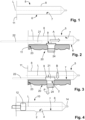
- FIG 1 shows a sectional view of a preform 5 for the production of an injection device 10 with a bypass channel 2 (see FIG figure 4 ).
- the preform 5 consists of a cylindrical section 8 which is aligned along a longitudinal axis L.
- FIG. The cylindrical section 8 defines a cylindrical outer surface 6 and a cylindrical inner surface 7.
- the preform 5 also has a handle 11 which is used during the manufacturing process for positioning the preform 5 in a tool 20 (see figure 2 ) can be used.
- FIG 2 also shows a sectional view along the longitudinal axis L of the preform 5.
- the preform 5 is already positioned in a specially designed tool 20 here.
- the tool defines a stop 23 which interacts with the handle 11 of the preform 5 . This achieves a reproducible positioning of the preform 5 in the tool 20 .
- the tool 20 also includes a heat source 24 for heating a Portion 9 of the cylindrical portion 8 of the preform 5 is suitable.
- the heat source 24 can be in the form of a contact heat source and/or a radiant heat source.
- the preform 5 thus rests in the tool with a cylindrical outer surface 6 of the cylindrical section 8 .
- the heat source 24 heats the partial area 9 of the cylindrical section 8 to a temperature such that the material of the preform 5 can be plastically deformed.
- a stamp 21 can be inserted into the preform 5 in the axial direction A at the same time as the partial area 9 of the cylindrical section 8 is heated.
- the plunger 21 is preferably attached to a handle
- figure 3 12 shows the situation in which the stamp 21 has been moved in a radial direction B towards the partial area 9 of the cylindrical section 8.
- the preform 5 is preferably injection molded from a thermoplastic material.
- the materials used for the preform 5 are COC, COP and PP.
- the movement of the plunger 21 in the radial direction B is essentially brought about by the handle 22 .
- a pressure P is exerted on the plunger 21 in the radial direction B via the handle 22 , which pressure ensures plastic deformation of the heated partial area 9 .
- FIG 4 shows a sectional view of the injection device 10 produced with the method according to the invention along the longitudinal axis L.
- the bypass channel 2 is formed in the cylindrical section 8 .
- the cylindrical section 8 is here from the cylindrical inner surface 7 in the partial area 9 (see figure 2 + 3) curved outwards, so that as a result the cylindrical section 8 of the injection device 10 has formed an undercut 4 .
- a plunger 12 can also be inserted into the injection device 10 , with which the material present in the injection device 10 can be discharged through a nozzle 14 of the injection device 10 .
Landscapes
- Engineering & Computer Science (AREA)
- Mechanical Engineering (AREA)
- Health & Medical Sciences (AREA)
- Animal Behavior & Ethology (AREA)
- Public Health (AREA)
- Heart & Thoracic Surgery (AREA)
- Hematology (AREA)
- Life Sciences & Earth Sciences (AREA)
- Anesthesiology (AREA)
- General Health & Medical Sciences (AREA)
- Biomedical Technology (AREA)
- Veterinary Medicine (AREA)
- Manufacturing & Machinery (AREA)
- Vascular Medicine (AREA)
- Processing And Handling Of Plastics And Other Materials For Molding In General (AREA)
- Blow-Moulding Or Thermoforming Of Plastics Or The Like (AREA)
- Injection Moulding Of Plastics Or The Like (AREA)
Description
- Die Erfindung betrifft ein Verfahren zum Herstellen einer Injektionsvorrichtung mit Bypasskanal.
- Ferner betrifft die Erfindung ein Werkzeug für das Verfahren zum Herstellen einer Injektionsvorrichtung mit Bypasskanal.
- Die deutsche Patentanmeldung
DE 10 2007 014 281 A1 offenbart ein Verfahren zum Herstellen einer Mehrkammer-Spritze mit Bypasskanal. Hierzu wird zunächst ein Vorformling aus einem thermoformbaren Kunststoff mit einem rohrförmigen Abschnitt hergestellt. Der Vorformling wird in dem Bereich, in dem der Bypasskanal ausgebildet werden soll, mit einer Matrize umschlossen. Die Matrize hat in dem Bereich des Bypasskanals eine Vertiefung ausgebildet. Der Vorformling wird erwärmt und zwar auf eine Temperatur oberhalb des Erweichungsbereiches des Kunststoffs. Der rohrförmige Abschnitt des Vorformlings wird in der Matrize positioniert und mit Druck beaufschlagt. Aufgrund der Druckdifferenz wird die Wandung des Vorformlings in die Vertiefungen der Matrize gedrückt, so dass dadurch der Bypasskanal plastisch ausgeformt wird. Der Nachteil dieses Verfahrens ist, dass sich mit dem zusätzlichen Werkzeug (Matrize) und dem erforderlichen Anlegen eines Drucks im Vorformling die Produktionskosten und die Zykluszeit für die Herstellung einer Mehrkammer-Spritze mit Bypasskanal erhöhen.DE 10 2007 014 281 A1 offenbart ebenfalls ein Verfahren und ein Werkzeug zum Herstellen einer Injektionsvorrichtung mit einem Bypasskanal vermittels einer Matrize. - Die
deutsche Offenlegungsschrift DE 29 25 858 offenbart einen Faltkern, mit dem Hinterschneidungen im Innern von Spritzgussteilen ausgebildet werden können. Mit dem Faltkern könnte auch der Bypasskanal in der Injektionsspritze geformt werden. Der Faltkern ist jedoch mechanisch aufwändig und würde beim Spritzgussprozess der Injektionssspritze doch auch zu Trennkanten und Partikelbildung führen. - Eine weitere Möglichkeit der Ausbildung des Bypasskanals in der Injektionsspritze ist, dass man Einlegeteile verwendet, die beim Spritzgussprozess den Bypasskanal formen. Hierzu würde ein zweites Werkzeug benötigt, was zu längeren Zyklen bei der Herstellung von Injektionsspritzen führt. Diese längeren Zyklen und das zweite Werkzeug erhöhen folglich die Teilepreise für die Injektionsspritze, die mit dem Bypasskanal versehen ist. Das Handling mit den Einlegeteilen führt ebenfalls zu längeren Zykluszeiten, höheren Kosten und die Partikelbildung kann beim Spritzgussprozess nicht ausgeschlossen werden.
- Der Bypasskanal in der Injektionsspritze könnte auch mittels eines Zweikomponenten-Spritzgussverfahrens hergestellt werden. Der Zweikomponenten-Spritzguss hat jedoch den Nachteil, dass dieser zu höheren Werkzeugkosten und zu einer niedrigeren Belegung des Werkzeugs führt. Das Werkzeug selbst ist sehr komplex und somit auch anfällig. Letztendlich führt der Zweikomponenten-Spritzguss ebenfalls zu höheren Teilepreisen.
-
US 3 932 093 A undFR 2 244 609 A1 - Der Erfindung liegt die Aufgabe zugrunde, ein Verfahren zum Herstellen einer Injektionsvorrichtung mit einem Bypasskanal zu schaffen, das einfach und zuverlässig zu handhaben ist und die Kosten pro hergestellter Injektionsvorrichtung senkt.
- Diese Aufgabe wird durch ein Verfahren zum Herstellen einer Injektionsvorrichtung mit einem Bypasskanal gelöst, das die Merkmale des Anspruchs 1 umfasst.
- Ferner liegt der Erfindung die Aufgabe zugrunde, ein Werkzeug zum Herstellen einer Injektionsvorrichtung mit Bypasskanal zu schaffen, mit dem auf einfache, zuverlässige und kostengünstige Weise der Bypasskanal in der Injektionsvorrichtung ausgeformt werden kann.
- Diese Aufgabe wird durch ein Werkzeug gelöst, dass die Merkmale des Anspruchs 5 umfasst.
- Das erfindungsgemäße Verfahren zum Herstellen einer Injektionsvorrichtung mit einem Bypasskanal zeichnet sich dadurch aus, dass zunächst ein Vorformling in ein Werkzeug eingelegt wird. Dabei liegt der Vorformling teilweise mit einer zylindrischen Außenfläche eines zylinderförmigen Abschnitts im Werkzeug auf. Anschließend erfolgt ein Erwärmen eines Teilbereichs des zylinderförmigen Abschnitts. Parallel dazu kann ein Stempel in den zylinderförmigen Abschnitt im Wesentlichen in axialer Richtung eingeschoben werden. Wenn sich der Stempel in der Position zum erwärmten Teilbereich befindet, wird der Stempel in radialer Richtung auf eine zylindrische Innenfläche des zylinderförmigen Abschnitts des Vorformlings verschoben. Der Stempel wird dann in den erwärmten Teilbereich des zylinderförmigen Abschnitts eingedrückt und dabei der Bypasskanal durch plastische Verformung des erwärmten Teilbereichs ausgeformt.
- Das erfindungsgemäße Verfahren hat den Vorteil, dass der Bypasskanal mittels dem Stempel, z.B. nach dem Spritzgussprozess, geformt wird. Durch die Benutzung des Stempels können aufwendige Betriebsmittel gespart werden und im Körper der Injektionsspritze entstehen keine Partikel oder Trennungen, die zu Verunreinigungen beim fertigen Produkt führen würden.
- Der Teilbereich des zylinderförmigen Abschnitts wird mit einer Wärmequelle erwärmt, bzw. erhitzt. Mit der Wärmequelle wird das Material des Teilbereichs auf eine derartige Temperatur gebracht, dass das Material des Vorformlings plastisch durch den Druck des Stempels in radialer Richtung verformt werden kann. Das Erwärmen des Teilbereichs des zylinderförmigen Abschnitts kann mittels der Wärmequelle durch Strahlungswärme und/oder Kontaktwärme durchgeführt werden.
- Der Vorformling für die Injektionsvorrichtung kann dabei aus Cyclo-Olefin-Copolymer (COC), Cyclic-Olefin-Polymer (COP) oder aus Polypropylen (PP) spritzgegossen werden.
- Durch das Eindrücken des Stempels in den erwärmten Teilbereich des zylinderförmigen Abschnitts erfolgt eine plastische Deformation, durch die ein Hinterschnitt im Teilbereich des zylinderförmigen Abschnitts ausgebildet wird. Der Hinterschnitt definiert den Bypasskanal, der von der zylinderförmigen Innenfläche des Vorformlings nach außen gedrückt wird.
- Das Werkzeug zur Herstellung einer Injektionsvorrichtung mit Bypasskanal zeichnet sich auch dadurch aus, dass es derart ausgebildet ist, dass ein Vorformling der Injektionsvorrichtung im Werkzeug in zumindest einem zylinderförmigen Abschnitt unterstützt ist. Eine Wärmequelle im Werkzeug ist zum Erwärmen eines Teilbereichs des zylinderförmigen Abschnitts des Vorformlings gegenüber einer zylindrischen Außenfläche des zylinderförmigen Abschnitts angeordnet. Ferner umfasst das Werkzeug einen Stempel, der in den Vorformling in einer axialen Richtung einfahrbar ist. Ebenso ist der Stempel derart ausgebildet, dass er im Vorformling in einer radialen Richtung zum erwärmten Teilbereich hin verfahrbar ist.
- Die Wärmequelle kann als eine Kontaktwärmequelle und/oder als eine Strahlungswärmequelle ausgebildet sein. Zur Positionierung des Vorformlings im Werkzeug, hat dieses einen Anschlag für eine Handhabe des Vorformlings ausgebildet. Dies hat den Vorteil, dass der Vorformling mit dem zu erwärmenden Teilbereich reproduzierbar gegenüber der Wärmequelle des Werkzeugs positioniert ist.
- Der Stempel selbst ist an einer Handhabe angebracht, mittels der der Stempel in den Vorformling in der axialen Richtung einfahrbar ist. Ebenso ist über die Handhabe der Vorformling in der radialen Richtung zum erwärmten Teilbereich hin verfahrbar. Über die Handhabe des Stempels kann auf den erwärmten Teilbereich mit dem Stempel ein derartiger Druck ausgeübt werden, dass der Stempel in dem erwärmten Material des zylinderförmigen Bereichs, bzw. des Teilbereichs des Vorformlings den Basiskanal formt. Nach dem Erkalten kann die Injektionsvorrichtung mit dem ausgeformten Bypasskanal aus dem Werkzeug entnommen werden.
- Weitere Vorteile und vorteilhafte Ausgestaltungen der Erfindung sind Gegenstand der nachfolgenden Figuren, sowie deren Beschreibungsteile.
- Es zeigen im Einzelnen:
- Figur 1
- eine Schnittansicht eines Vorformlings entlang einer Längsachse.
- Figur 2
- eine Schnittansicht des in
Figur 1 dargestellten Vorformlings, der im Werkzeug positioniert ist; - Figur 3
- eine Schnittansicht des Vorformlings, der im Werkzeugs positioniert ist und bei dem der Bypasskanal ausgeformt wird; und
- Figur 4
- eine Schnittansicht der erfindungsgemäßen Injektionsvorrichtung mit dem ausgeformten Bypasskanal.
- Für gleiche oder gleich wirkende Elemente der Erfindung werden identische Bezugszeichen verwendet. Das dargestellte Ausführungsbeispiel für die Ausformung eines Bypasskanals für eine Injektionsvorrichtung stellt lediglich eine mögliche Ausführungsform dar, wie das erfindungsgemäße Verfahren ausgestaltet sein kann. Dies soll nicht als eine Beschränkung der Erfindung aufgefasst werden.
-
Figur 1 zeigt eine Schnittansicht eines Vorformlings 5 für die Herstellung einer Injektionsvorrichtung 10 mit einem Bypasskanal 2 (sieheFigur 4 ). Der Vorformling 5 besteht aus einem zylinderförmigen Abschnitt 8, der entlang einer Längsachse L ausgerichtet ist. Der zylinderförmige Abschnitt 8 definiert eine zylindrische Außenfläche 6 und eine zylindrische Innenfläche 7. Ebenso hat der Vorformling 5 eine Handhabe 11 ausgebildet, die beim Herstellungsprozess für die Positionierung des Vorformlings 5 in einem Werkzeug 20 (sieheFigur 2 ) herangezogen werden kann. -
Figur 2 zeigt ebenfalls eine Schnittansicht entlang der Längsachse L des Vorformlings 5. Der Vorformling 5 ist hier bereits in einem speziell ausgebildeten Werkzeug 20 positioniert. Das Werkzeug definiert einen Anschlag 23, der mit der Handhabe 11 des Vorformlings 5 zusammenwirkt. Dadurch wird eine reproduzierbare Positionierung des Vorformlings 5 im Werkzeug 20 erreicht. Das Werkzeug 20 umfasst ebenfalls eine Wärmequelle 24, die zum Erwärmen eines Teilbereichs 9 des zylinderförmigen Abschnitts 8 des Vorformlings 5 geeignet ist. Die Wärmequelle 24 kann dabei in Form einer Kontaktwärmequelle und/oder einer Strahlungswärmequelle ausgebildet sein. Der Vorformling 5 liegt somit mit einer zylindrischen Außenfläche 6 des zylindrischen Abschnitts 8 im Werkzeug auf. Die Wärmequelle 24 erwärmt dabei den Teilbereich 9 des zylinderförmigen Abschnitts 8 auf eine Temperatur, so dass das Material des Vorformlings 5 plastisch deformiert werden kann. Gleichzeitig zur Erwärmung des Teilbereichs 9 des zylinderförmigen Abschnitts 8 kann ein Stempel 21 in axialer Richtung A in den Vorformling 5 eingeführt werden. Bevorzugt ist dabei der Stempel 21 an einer Handhabe 22 angebracht. -
Figur 3 zeigt die Situation, dass der Stempel 21 in einer radialen Richtung B auf den Teilbereich 9 des zylinderförmigen Abschnitts 8 zubewegt wurde. Bevorzugt ist der Vorformling 5 aus einem thermoplastischen Kunststoff spritzgegossen. Im Besonderen werden für den Vorformling 5 die Materialien COC, COP und PP verwendet. Die Bewegung des Stempels 21 in radialer Richtung B wird im Wesentlichen durch die Handhabe 22 bewirkt. Sobald der Stempel 21 die zylindrische Innenfläche 7 des zylinderförmigen Abschnitts 8 erreicht, wird über die Handhabe 22 auf den Stempel 21 ein Druck P in radialer Richtung B ausgeübt, der für eine plastische Verformung des erwärmten Teilbereichs 9 sorgt. -
Figur 4 zeigt eine Schnittansicht der mit dem erfindungsgemäßen Verfahren hergestellten Injektionsvorrichtung 10 entlang der Längsachse L. Der Bypasskanal 2 ist dabei im zylinderförmigen Abschnitt 8 ausgebildet. Dabei ist der zylinderförmige Abschnitt 8 von der zylindrischen Innenfläche 7 her im Teilbereich 9 (sieheFigur 2 + 3) nach außen gewölbt, so dass dadurch der zylinderförmige Abschnitt 8 der Injektionsvorrichtung 10 einen Hinterschnitt 4 ausgebildet hat. In die Injektionsvorrichtung 10 kann ferner noch ein Kolben 12 eingesetzt werden, mit dem das in der Injektionsvorrichtung 10 vorhandene Material durch eine Düse 14 der Injektionsvorrichtung 10 ausgebracht werden kann. -
- 2
- Bypasskanal
- 4
- Hinterschnitt
- 5
- Vorformling
- 6
- zylindrische Außenfläche
- 7
- zylindrische Innenfläche
- 8
- zylinderförmiger Abschnitt
- 9
- Teilbereich
- 10
- Injektionsvorrichtung
- 11
- Handhabe
- 12
- Kolben
- 14
- Düse
- 20
- Werkzeug
- 21
- Stempel
- 22
- Handhabe
- 23
- Anschlag
- 24
- Wärmequelle
- A
- axiale Richtung
- B
- radiale Richtung
- L
- Längsachse
- P
- Druck
Claims (8)
- Verfahren zum Herstellen einer Injektionsvorrichtung (10) mit einem Bypasskanal (2), umfassend die folgenden Schritte:• Einlegen eines Vorformlings (5) in ein Werkzeug (20), so dass der Vorformling (5) teilweise mit einer zylindrischen Außenfläche (6) eines zylinderförmigen Abschnitts (8) im Werkzeug (20) aufliegt;
gekennzeichnet durch• Erwärmen eines Teilbereichs (9) des zylinderförmigen Abschnitts (8) mit einer Wärmequelle (24) des Werkzeugs (20) auf eine Temperatur, so dass das Material des Vorformlings (5) plastisch deformiert werden kann;• Einschieben eines Stempels (21) in den zylinderförmigen Abschnitt (8), im Wesentlichen in einer axialen Richtung (A);• Verschieben des Stempels (21) in einer radialen Richtung (B) auf eine zylindrische Innenfläche (7) des zylinderförmigen Abschnitts (8) des Vorformlings (5);• Eindrücken des Stempels (21) in den erwärmten Teilbereich (9) des zylinderförmigen Abschnitts (8), so dass durch einen Druck (P) des Stempels (21) in der radialen Richtung (B) der Bypasskanal (2) durch plastische Verformung des erwärmten Teilbereichs (9) ausgeformt wird. - Verfahren nach Anspruch 1, wobei das Erwärmen des Teilbereichs (9) des zylinderförmigen Abschnitts (8) mittels Strahlungswärme und/oder Kontaktwärme durchgeführt wird.
- Verfahren nach einem der vorangehenden Ansprüche, wobei der Vorformling (5) aus Cyclo-Olefin-Copolymer, Cyclic-Olefin-Polymer oder Polypropylen spritzgegossen ist.
- Verfahren nach einem der vorangehenden Ansprüche, wobei durch das Eindrücken des Stempels (21) in den erwärmten Teilbereich (9) des zylinderförmigen Abschnitts (8) durch die plastische Deformation ein Hinterschnitt (4) im Teilbereich (9) des zylinderförmigen Abschnitts (8) ausgebildet wird, wobei der Hinterschnitt (4) den Bypasskanal (2) definiert.
- Werkzeug (20) zum Herstellen einer Injektionsvorrichtung (10) mit einem Bypasskanal (2),
gekennzeichnet durcheine Auflage zum Unterstützen zumindest eines zylinderförmigen Abschnitts (8) eines Vorformlings (5),eine Wärmequelle (24) im Werkzeug (20) zum Erwärmen eines Teilbereichs (9) des zylinderförmigen Abschnitts (8) des Vorformlings (5) gegenüber einer zylindrischen Außenfläche (6) des zylinderförmigen Abschnitts (8); undeinen Stempel (21), der in den Vorformling (5) in einer axialen Richtung (A) einfahrbar und im Vorformling (5) in einer radialen Richtung (B) zum erwärmten Teilbereich (9) hin verfahrbar ist. - Werkzeug (20) nach Anspruch 5, wobei die Wärmequelle (24) eine Kontakt- und/oder eine Strahlungswärmequelle ist.
- Werkzeug (20) nach einem der vorangehenden Ansprüche 5 oder 6, wobei das Werkzeug (20) einen Anschlag (23) für eine Handhabe (11) des Vorformlings (5) ausgebildet hat, so dass der Vorformling (5) mit dem zu erwärmenden Teilbereich (9) reproduzierbar gegenüber der Wärmequelle (24) des Werkzeugs (20) positioniert ist.
- Werkzeug (20) nach Anspruch 5, wobei der Stempel (21) an einer Handhabe (22) angebracht ist, mittels der der Stempel (21) in den Vorformling (5) in der axialen Richtung (A) einfahrbar, im Vorformling (5) in der radialen Richtung (B) zum erwärmten Teilbereich (9) hin verfahrbar und auf den erwärmten Teilbereich (9) ein Druck (P) ausübbar ist, so dass der Stempel (21) den Bypasskanal (2) formt.
Applications Claiming Priority (1)
| Application Number | Priority Date | Filing Date | Title |
|---|---|---|---|
| DE102018108549.4A DE102018108549B4 (de) | 2018-04-11 | 2018-04-11 | Verfahren zum Herstellen einer Injektionsvorrichtung mit Bypasskanal und Werkzeug hierfür |
Publications (2)
| Publication Number | Publication Date |
|---|---|
| EP3556538A1 EP3556538A1 (de) | 2019-10-23 |
| EP3556538B1 true EP3556538B1 (de) | 2023-04-26 |
Family
ID=65818273
Family Applications (1)
| Application Number | Title | Priority Date | Filing Date |
|---|---|---|---|
| EP19163351.0A Active EP3556538B1 (de) | 2018-04-11 | 2019-03-18 | Verfahren zum herstellen einer injektionsvorrichtung mit bypasskanal und werkzeug hierfür |
Country Status (3)
| Country | Link |
|---|---|
| US (1) | US11458658B2 (de) |
| EP (1) | EP3556538B1 (de) |
| DE (1) | DE102018108549B4 (de) |
Cited By (1)
| Publication number | Priority date | Publication date | Assignee | Title |
|---|---|---|---|---|
| EP4670950A1 (de) | 2024-06-25 | 2025-12-31 | Stevanato Group S.P.A. | Vorrichtung zur herstellung eines bypasskanals in spritzenvorformlingen und verfahren zur herstellung eines bypasskanals in spritzenvorformlingen |
Families Citing this family (1)
| Publication number | Priority date | Publication date | Assignee | Title |
|---|---|---|---|---|
| EP4395665A1 (de) * | 2021-09-03 | 2024-07-10 | Biolife, LLC | Bypass-spritze |
Family Cites Families (7)
| Publication number | Priority date | Publication date | Assignee | Title |
|---|---|---|---|---|
| GB1274643A (en) | 1968-07-04 | 1972-05-17 | Diva Cars Ltd | Improvements relating to motor land vehicles |
| FR2244609B1 (de) * | 1973-09-21 | 1976-05-14 | Schnuelle Eckhard | |
| US3932093A (en) * | 1975-04-25 | 1976-01-13 | Maier Johann H | Tube expander apparatus |
| DE2925858A1 (de) | 1979-06-27 | 1981-01-22 | Pietsch Be We Form Werkzeug | Faltkern |
| DE102006047670A1 (de) * | 2006-10-09 | 2008-04-10 | Firma G.B. Boucherie N.V. | Spritzenkörper |
| DE102007014281A1 (de) | 2007-03-19 | 2008-09-25 | Schott Ag | Verfahren zur Herstellung einer Mehrkammer-Spritze mit Bypasskanal |
| DE102011107764A1 (de) * | 2011-07-15 | 2013-01-17 | Friedrich Sanner Gmbh & Co. Kg | Mehrkammer-Spritze |
-
2018
- 2018-04-11 DE DE102018108549.4A patent/DE102018108549B4/de active Active
-
2019
- 2019-03-18 EP EP19163351.0A patent/EP3556538B1/de active Active
- 2019-04-08 US US16/377,547 patent/US11458658B2/en active Active
Cited By (1)
| Publication number | Priority date | Publication date | Assignee | Title |
|---|---|---|---|---|
| EP4670950A1 (de) | 2024-06-25 | 2025-12-31 | Stevanato Group S.P.A. | Vorrichtung zur herstellung eines bypasskanals in spritzenvorformlingen und verfahren zur herstellung eines bypasskanals in spritzenvorformlingen |
Also Published As
| Publication number | Publication date |
|---|---|
| DE102018108549B4 (de) | 2022-01-05 |
| DE102018108549A1 (de) | 2019-10-17 |
| US11458658B2 (en) | 2022-10-04 |
| US20190315028A1 (en) | 2019-10-17 |
| EP3556538A1 (de) | 2019-10-23 |
Similar Documents
| Publication | Publication Date | Title |
|---|---|---|
| EP2504144B1 (de) | Verfahren und vorrichtung zum herstellen von formzierteilen | |
| EP3556538B1 (de) | Verfahren zum herstellen einer injektionsvorrichtung mit bypasskanal und werkzeug hierfür | |
| DE3518441C2 (de) | Verfahren zum Herstellen eines Verformlings für das Blasformen eines Hohlkörpers | |
| EP0280204B1 (de) | Verfahren und Vorrichtung zum Anformen eines Flansches an einem Hohlkörper aus thermoplastischem Kunststoff | |
| DE102008009895A1 (de) | Bauteil, insbesondere Innenverkleidungsteil für Kraftfahrzeug, und Herstellverfahren | |
| EP2585276A1 (de) | Verfahren und vorrichtung zur herstellung eines bauteils | |
| DE2758188C3 (de) | Verfahren zum Formen einer Ringnut im Endabschnitt eines Rohres aus thermoplastischem Kunststoff | |
| WO2010051866A1 (de) | Verfahren und vorrichtung zur herstellung eines formteils mit dekoroberfläche | |
| EP3463802B1 (de) | Streckgeblasener kunststoffbehälter mit einem integriert ausgebildeten griffbereich und herstellverfahren für den kunststoffbehälter | |
| DE202016102996U1 (de) | Vorrichtung zum Herstellen einer Bürste | |
| WO2016030293A1 (de) | System zur weiterbehandlung von mittels spritzgiessen hergestellter vorformlinge | |
| DE69423536T2 (de) | Verfahren und Vorrichtung zur Herstellung eines Halteflansches um eine Behälteröffnung | |
| DE102008037131B4 (de) | Vorrichtung zum Herstellen eines formstabilen, sichtbaren Verkleidungsteils für ein Kraftfahrzeug sowie form- und narbgebende Schale zum lösbaren Verbinden mit einer Werkzeughälfte einer Spritzgießmaschine | |
| DE3511954C2 (de) | Verfahren und Vorrichtung zur Herstellung von Formpreßteilen, die an mindestens einem Rand mit einem thermoplastischen Randstreifen, insbesondere einer Dichtlippe od.dgl. verbunden sind | |
| EP3613550B1 (de) | Verfahren und vorrichtung zum herstellen eines kaschierten formteils | |
| DE102015010434A1 (de) | Verfahren und Einrichtung zum Herstellen eines Verbundbauteils | |
| DE102011108942B4 (de) | Verfahren zur Herstellung eines Bauteils aus einem ersten und einem zweiten Material | |
| DE102018207937A1 (de) | Verfahren zum Herstellen eines Sandwichbauteils | |
| EP0883480B1 (de) | Verfahren und vorrichtung zum biegen eines bauteils aus einem thermoplastischen kunststoff | |
| DE4000799B4 (de) | Verfahren zum Auskleiden eines Meßrohrs eines Durchflußmeßgeräts | |
| DE1479073A1 (de) | Vorrichtung zur nachtraeglichen AEnderung des Querschnitts von Hohlprofilen aus thermisch verformbaren Materialien | |
| EP2576177B1 (de) | Verfahren und vorrichtung zur innenhochdruckumformung eines ausgangshalbzeuges | |
| DE102016108290B3 (de) | Schweisswerkzeug und verfahren zum verschweissen von kunststoffteilen | |
| DE19632279C2 (de) | Verfahren zur Herstellung eines scheibenförmigen Teiles | |
| DE19535875C2 (de) | Verfahren zum Etikettieren von Gegenständen |
Legal Events
| Date | Code | Title | Description |
|---|---|---|---|
| PUAI | Public reference made under article 153(3) epc to a published international application that has entered the european phase |
Free format text: ORIGINAL CODE: 0009012 |
|
| STAA | Information on the status of an ep patent application or granted ep patent |
Free format text: STATUS: THE APPLICATION HAS BEEN PUBLISHED |
|
| AK | Designated contracting states |
Kind code of ref document: A1 Designated state(s): AL AT BE BG CH CY CZ DE DK EE ES FI FR GB GR HR HU IE IS IT LI LT LU LV MC MK MT NL NO PL PT RO RS SE SI SK SM TR |
|
| AX | Request for extension of the european patent |
Extension state: BA ME |
|
| STAA | Information on the status of an ep patent application or granted ep patent |
Free format text: STATUS: REQUEST FOR EXAMINATION WAS MADE |
|
| 17P | Request for examination filed |
Effective date: 20200402 |
|
| RBV | Designated contracting states (corrected) |
Designated state(s): AL AT BE BG CH CY CZ DE DK EE ES FI FR GB GR HR HU IE IS IT LI LT LU LV MC MK MT NL NO PL PT RO RS SE SI SK SM TR |
|
| STAA | Information on the status of an ep patent application or granted ep patent |
Free format text: STATUS: EXAMINATION IS IN PROGRESS |
|
| 17Q | First examination report despatched |
Effective date: 20201130 |
|
| GRAP | Despatch of communication of intention to grant a patent |
Free format text: ORIGINAL CODE: EPIDOSNIGR1 |
|
| STAA | Information on the status of an ep patent application or granted ep patent |
Free format text: STATUS: GRANT OF PATENT IS INTENDED |
|
| INTG | Intention to grant announced |
Effective date: 20221011 |
|
| GRAS | Grant fee paid |
Free format text: ORIGINAL CODE: EPIDOSNIGR3 |
|
| GRAA | (expected) grant |
Free format text: ORIGINAL CODE: 0009210 |
|
| STAA | Information on the status of an ep patent application or granted ep patent |
Free format text: STATUS: THE PATENT HAS BEEN GRANTED |
|
| AK | Designated contracting states |
Kind code of ref document: B1 Designated state(s): AL AT BE BG CH CY CZ DE DK EE ES FI FR GB GR HR HU IE IS IT LI LT LU LV MC MK MT NL NO PL PT RO RS SE SI SK SM TR |
|
| REG | Reference to a national code |
Ref country code: GB Ref legal event code: FG4D Free format text: NOT ENGLISH |
|
| REG | Reference to a national code |
Ref country code: CH Ref legal event code: EP |
|
| REG | Reference to a national code |
Ref country code: DE Ref legal event code: R096 Ref document number: 502019007532 Country of ref document: DE |
|
| REG | Reference to a national code |
Ref country code: AT Ref legal event code: REF Ref document number: 1562525 Country of ref document: AT Kind code of ref document: T Effective date: 20230515 |
|
| REG | Reference to a national code |
Ref country code: IE Ref legal event code: FG4D Free format text: LANGUAGE OF EP DOCUMENT: GERMAN |
|
| REG | Reference to a national code |
Ref country code: LT Ref legal event code: MG9D |
|
| REG | Reference to a national code |
Ref country code: NL Ref legal event code: MP Effective date: 20230426 |
|
| PG25 | Lapsed in a contracting state [announced via postgrant information from national office to epo] |
Ref country code: NL Free format text: LAPSE BECAUSE OF FAILURE TO SUBMIT A TRANSLATION OF THE DESCRIPTION OR TO PAY THE FEE WITHIN THE PRESCRIBED TIME-LIMIT Effective date: 20230426 |
|
| PG25 | Lapsed in a contracting state [announced via postgrant information from national office to epo] |
Ref country code: SE Free format text: LAPSE BECAUSE OF FAILURE TO SUBMIT A TRANSLATION OF THE DESCRIPTION OR TO PAY THE FEE WITHIN THE PRESCRIBED TIME-LIMIT Effective date: 20230426 Ref country code: PT Free format text: LAPSE BECAUSE OF FAILURE TO SUBMIT A TRANSLATION OF THE DESCRIPTION OR TO PAY THE FEE WITHIN THE PRESCRIBED TIME-LIMIT Effective date: 20230828 Ref country code: NO Free format text: LAPSE BECAUSE OF FAILURE TO SUBMIT A TRANSLATION OF THE DESCRIPTION OR TO PAY THE FEE WITHIN THE PRESCRIBED TIME-LIMIT Effective date: 20230726 Ref country code: ES Free format text: LAPSE BECAUSE OF FAILURE TO SUBMIT A TRANSLATION OF THE DESCRIPTION OR TO PAY THE FEE WITHIN THE PRESCRIBED TIME-LIMIT Effective date: 20230426 |
|
| PG25 | Lapsed in a contracting state [announced via postgrant information from national office to epo] |
Ref country code: RS Free format text: LAPSE BECAUSE OF FAILURE TO SUBMIT A TRANSLATION OF THE DESCRIPTION OR TO PAY THE FEE WITHIN THE PRESCRIBED TIME-LIMIT Effective date: 20230426 Ref country code: PL Free format text: LAPSE BECAUSE OF FAILURE TO SUBMIT A TRANSLATION OF THE DESCRIPTION OR TO PAY THE FEE WITHIN THE PRESCRIBED TIME-LIMIT Effective date: 20230426 Ref country code: LV Free format text: LAPSE BECAUSE OF FAILURE TO SUBMIT A TRANSLATION OF THE DESCRIPTION OR TO PAY THE FEE WITHIN THE PRESCRIBED TIME-LIMIT Effective date: 20230426 Ref country code: LT Free format text: LAPSE BECAUSE OF FAILURE TO SUBMIT A TRANSLATION OF THE DESCRIPTION OR TO PAY THE FEE WITHIN THE PRESCRIBED TIME-LIMIT Effective date: 20230426 Ref country code: IS Free format text: LAPSE BECAUSE OF FAILURE TO SUBMIT A TRANSLATION OF THE DESCRIPTION OR TO PAY THE FEE WITHIN THE PRESCRIBED TIME-LIMIT Effective date: 20230826 Ref country code: HR Free format text: LAPSE BECAUSE OF FAILURE TO SUBMIT A TRANSLATION OF THE DESCRIPTION OR TO PAY THE FEE WITHIN THE PRESCRIBED TIME-LIMIT Effective date: 20230426 Ref country code: GR Free format text: LAPSE BECAUSE OF FAILURE TO SUBMIT A TRANSLATION OF THE DESCRIPTION OR TO PAY THE FEE WITHIN THE PRESCRIBED TIME-LIMIT Effective date: 20230727 |
|
| PG25 | Lapsed in a contracting state [announced via postgrant information from national office to epo] |
Ref country code: FI Free format text: LAPSE BECAUSE OF FAILURE TO SUBMIT A TRANSLATION OF THE DESCRIPTION OR TO PAY THE FEE WITHIN THE PRESCRIBED TIME-LIMIT Effective date: 20230426 |
|
| PG25 | Lapsed in a contracting state [announced via postgrant information from national office to epo] |
Ref country code: SK Free format text: LAPSE BECAUSE OF FAILURE TO SUBMIT A TRANSLATION OF THE DESCRIPTION OR TO PAY THE FEE WITHIN THE PRESCRIBED TIME-LIMIT Effective date: 20230426 |
|
| P01 | Opt-out of the competence of the unified patent court (upc) registered |
Effective date: 20231220 |
|
| REG | Reference to a national code |
Ref country code: DE Ref legal event code: R097 Ref document number: 502019007532 Country of ref document: DE |
|
| PG25 | Lapsed in a contracting state [announced via postgrant information from national office to epo] |
Ref country code: SM Free format text: LAPSE BECAUSE OF FAILURE TO SUBMIT A TRANSLATION OF THE DESCRIPTION OR TO PAY THE FEE WITHIN THE PRESCRIBED TIME-LIMIT Effective date: 20230426 Ref country code: SK Free format text: LAPSE BECAUSE OF FAILURE TO SUBMIT A TRANSLATION OF THE DESCRIPTION OR TO PAY THE FEE WITHIN THE PRESCRIBED TIME-LIMIT Effective date: 20230426 Ref country code: RO Free format text: LAPSE BECAUSE OF FAILURE TO SUBMIT A TRANSLATION OF THE DESCRIPTION OR TO PAY THE FEE WITHIN THE PRESCRIBED TIME-LIMIT Effective date: 20230426 Ref country code: EE Free format text: LAPSE BECAUSE OF FAILURE TO SUBMIT A TRANSLATION OF THE DESCRIPTION OR TO PAY THE FEE WITHIN THE PRESCRIBED TIME-LIMIT Effective date: 20230426 Ref country code: DK Free format text: LAPSE BECAUSE OF FAILURE TO SUBMIT A TRANSLATION OF THE DESCRIPTION OR TO PAY THE FEE WITHIN THE PRESCRIBED TIME-LIMIT Effective date: 20230426 Ref country code: CZ Free format text: LAPSE BECAUSE OF FAILURE TO SUBMIT A TRANSLATION OF THE DESCRIPTION OR TO PAY THE FEE WITHIN THE PRESCRIBED TIME-LIMIT Effective date: 20230426 |
|
| PLBE | No opposition filed within time limit |
Free format text: ORIGINAL CODE: 0009261 |
|
| STAA | Information on the status of an ep patent application or granted ep patent |
Free format text: STATUS: NO OPPOSITION FILED WITHIN TIME LIMIT |
|
| 26N | No opposition filed |
Effective date: 20240129 |
|
| PG25 | Lapsed in a contracting state [announced via postgrant information from national office to epo] |
Ref country code: SI Free format text: LAPSE BECAUSE OF FAILURE TO SUBMIT A TRANSLATION OF THE DESCRIPTION OR TO PAY THE FEE WITHIN THE PRESCRIBED TIME-LIMIT Effective date: 20230426 |
|
| PG25 | Lapsed in a contracting state [announced via postgrant information from national office to epo] |
Ref country code: SI Free format text: LAPSE BECAUSE OF FAILURE TO SUBMIT A TRANSLATION OF THE DESCRIPTION OR TO PAY THE FEE WITHIN THE PRESCRIBED TIME-LIMIT Effective date: 20230426 Ref country code: IT Free format text: LAPSE BECAUSE OF FAILURE TO SUBMIT A TRANSLATION OF THE DESCRIPTION OR TO PAY THE FEE WITHIN THE PRESCRIBED TIME-LIMIT Effective date: 20230426 |
|
| REG | Reference to a national code |
Ref country code: CH Ref legal event code: PL |
|
| PG25 | Lapsed in a contracting state [announced via postgrant information from national office to epo] |
Ref country code: BG Free format text: LAPSE BECAUSE OF FAILURE TO SUBMIT A TRANSLATION OF THE DESCRIPTION OR TO PAY THE FEE WITHIN THE PRESCRIBED TIME-LIMIT Effective date: 20230426 |
|
| PG25 | Lapsed in a contracting state [announced via postgrant information from national office to epo] |
Ref country code: LU Free format text: LAPSE BECAUSE OF NON-PAYMENT OF DUE FEES Effective date: 20240318 |
|
| PG25 | Lapsed in a contracting state [announced via postgrant information from national office to epo] |
Ref country code: MC Free format text: LAPSE BECAUSE OF FAILURE TO SUBMIT A TRANSLATION OF THE DESCRIPTION OR TO PAY THE FEE WITHIN THE PRESCRIBED TIME-LIMIT Effective date: 20230426 |
|
| PG25 | Lapsed in a contracting state [announced via postgrant information from national office to epo] |
Ref country code: MC Free format text: LAPSE BECAUSE OF FAILURE TO SUBMIT A TRANSLATION OF THE DESCRIPTION OR TO PAY THE FEE WITHIN THE PRESCRIBED TIME-LIMIT Effective date: 20230426 Ref country code: LU Free format text: LAPSE BECAUSE OF NON-PAYMENT OF DUE FEES Effective date: 20240318 Ref country code: BG Free format text: LAPSE BECAUSE OF FAILURE TO SUBMIT A TRANSLATION OF THE DESCRIPTION OR TO PAY THE FEE WITHIN THE PRESCRIBED TIME-LIMIT Effective date: 20230426 |
|
| REG | Reference to a national code |
Ref country code: BE Ref legal event code: MM Effective date: 20240331 |
|
| PG25 | Lapsed in a contracting state [announced via postgrant information from national office to epo] |
Ref country code: BE Free format text: LAPSE BECAUSE OF NON-PAYMENT OF DUE FEES Effective date: 20240331 |
|
| PG25 | Lapsed in a contracting state [announced via postgrant information from national office to epo] |
Ref country code: IE Free format text: LAPSE BECAUSE OF NON-PAYMENT OF DUE FEES Effective date: 20240318 |
|
| PG25 | Lapsed in a contracting state [announced via postgrant information from national office to epo] |
Ref country code: IE Free format text: LAPSE BECAUSE OF NON-PAYMENT OF DUE FEES Effective date: 20240318 Ref country code: BE Free format text: LAPSE BECAUSE OF NON-PAYMENT OF DUE FEES Effective date: 20240331 Ref country code: CH Free format text: LAPSE BECAUSE OF NON-PAYMENT OF DUE FEES Effective date: 20240331 |
|
| PGFP | Annual fee paid to national office [announced via postgrant information from national office to epo] |
Ref country code: DE Payment date: 20250319 Year of fee payment: 7 |
|
| PGFP | Annual fee paid to national office [announced via postgrant information from national office to epo] |
Ref country code: FR Payment date: 20250324 Year of fee payment: 7 |
|
| PGFP | Annual fee paid to national office [announced via postgrant information from national office to epo] |
Ref country code: GB Payment date: 20250324 Year of fee payment: 7 |
|
| REG | Reference to a national code |
Ref country code: AT Ref legal event code: MM01 Ref document number: 1562525 Country of ref document: AT Kind code of ref document: T Effective date: 20240318 |
|
| PG25 | Lapsed in a contracting state [announced via postgrant information from national office to epo] |
Ref country code: AT Free format text: LAPSE BECAUSE OF NON-PAYMENT OF DUE FEES Effective date: 20240318 |
|
| PG25 | Lapsed in a contracting state [announced via postgrant information from national office to epo] |
Ref country code: CY Free format text: LAPSE BECAUSE OF FAILURE TO SUBMIT A TRANSLATION OF THE DESCRIPTION OR TO PAY THE FEE WITHIN THE PRESCRIBED TIME-LIMIT; INVALID AB INITIO Effective date: 20190318 |
|
| PG25 | Lapsed in a contracting state [announced via postgrant information from national office to epo] |
Ref country code: HU Free format text: LAPSE BECAUSE OF FAILURE TO SUBMIT A TRANSLATION OF THE DESCRIPTION OR TO PAY THE FEE WITHIN THE PRESCRIBED TIME-LIMIT; INVALID AB INITIO Effective date: 20190318 |
|
| PGFP | Annual fee paid to national office [announced via postgrant information from national office to epo] |
Ref country code: MK Payment date: 20250307 Year of fee payment: 7 |
|
| PG25 | Lapsed in a contracting state [announced via postgrant information from national office to epo] |
Ref country code: TR Free format text: LAPSE BECAUSE OF FAILURE TO SUBMIT A TRANSLATION OF THE DESCRIPTION OR TO PAY THE FEE WITHIN THE PRESCRIBED TIME-LIMIT Effective date: 20230426 |