EP3556422A1 - Set de pansement protecteur de catheter - Google Patents
Set de pansement protecteur de catheter Download PDFInfo
- Publication number
- EP3556422A1 EP3556422A1 EP19170378.4A EP19170378A EP3556422A1 EP 3556422 A1 EP3556422 A1 EP 3556422A1 EP 19170378 A EP19170378 A EP 19170378A EP 3556422 A1 EP3556422 A1 EP 3556422A1
- Authority
- EP
- European Patent Office
- Prior art keywords
- dressing
- catheter
- pouch
- patient
- tube
- Prior art date
- Legal status (The legal status is an assumption and is not a legal conclusion. Google has not performed a legal analysis and makes no representation as to the accuracy of the status listed.)
- Granted
Links
- 230000001681 protective effect Effects 0.000 title claims abstract description 17
- 230000001070 adhesive effect Effects 0.000 claims description 33
- 239000000853 adhesive Substances 0.000 claims description 32
- 229920002635 polyurethane Polymers 0.000 claims description 15
- 239000004814 polyurethane Substances 0.000 claims description 15
- 239000000463 material Substances 0.000 claims description 7
- 239000010410 layer Substances 0.000 description 35
- 238000000502 dialysis Methods 0.000 description 15
- 238000001631 haemodialysis Methods 0.000 description 14
- 230000000322 hemodialysis Effects 0.000 description 14
- 229920001296 polysiloxane Polymers 0.000 description 12
- 210000001015 abdomen Anatomy 0.000 description 11
- 239000003292 glue Substances 0.000 description 7
- 208000015181 infectious disease Diseases 0.000 description 5
- 206010020751 Hypersensitivity Diseases 0.000 description 4
- 229920000297 Rayon Polymers 0.000 description 4
- 230000007815 allergy Effects 0.000 description 4
- 239000008280 blood Substances 0.000 description 4
- 210000004369 blood Anatomy 0.000 description 4
- 230000000474 nursing effect Effects 0.000 description 4
- -1 polyéthylène Polymers 0.000 description 4
- WQZGKKKJIJFFOK-GASJEMHNSA-N Glucose Natural products OC[C@H]1OC(O)[C@H](O)[C@@H](O)[C@@H]1O WQZGKKKJIJFFOK-GASJEMHNSA-N 0.000 description 3
- NIXOWILDQLNWCW-UHFFFAOYSA-N acrylic acid group Chemical group C(C=C)(=O)O NIXOWILDQLNWCW-UHFFFAOYSA-N 0.000 description 3
- 239000008103 glucose Substances 0.000 description 3
- 210000002784 stomach Anatomy 0.000 description 3
- 238000012800 visualization Methods 0.000 description 3
- XLYOFNOQVPJJNP-UHFFFAOYSA-N water Substances O XLYOFNOQVPJJNP-UHFFFAOYSA-N 0.000 description 3
- 239000004952 Polyamide Substances 0.000 description 2
- 239000004698 Polyethylene Substances 0.000 description 2
- 239000012790 adhesive layer Substances 0.000 description 2
- 239000002390 adhesive tape Substances 0.000 description 2
- 210000000038 chest Anatomy 0.000 description 2
- 239000004816 latex Substances 0.000 description 2
- 229920000126 latex Polymers 0.000 description 2
- 238000004519 manufacturing process Methods 0.000 description 2
- 238000012544 monitoring process Methods 0.000 description 2
- 125000005498 phthalate group Chemical group 0.000 description 2
- 229920002647 polyamide Polymers 0.000 description 2
- 229920000728 polyester Polymers 0.000 description 2
- 229920000573 polyethylene Polymers 0.000 description 2
- 239000004447 silicone coating Substances 0.000 description 2
- VPWNQTHUCYMVMZ-UHFFFAOYSA-N 4,4'-sulfonyldiphenol Chemical class C1=CC(O)=CC=C1S(=O)(=O)C1=CC=C(O)C=C1 VPWNQTHUCYMVMZ-UHFFFAOYSA-N 0.000 description 1
- 229930185605 Bisphenol Natural products 0.000 description 1
- 201000004624 Dermatitis Diseases 0.000 description 1
- 206010061218 Inflammation Diseases 0.000 description 1
- 206010040914 Skin reaction Diseases 0.000 description 1
- 239000003522 acrylic cement Substances 0.000 description 1
- 208000030961 allergic reaction Diseases 0.000 description 1
- 230000015556 catabolic process Effects 0.000 description 1
- 231100000749 chronicity Toxicity 0.000 description 1
- 239000011248 coating agent Substances 0.000 description 1
- 238000000576 coating method Methods 0.000 description 1
- 230000000295 complement effect Effects 0.000 description 1
- 230000003247 decreasing effect Effects 0.000 description 1
- 238000006731 degradation reaction Methods 0.000 description 1
- 230000032798 delamination Effects 0.000 description 1
- 239000000839 emulsion Substances 0.000 description 1
- 206010014665 endocarditis Diseases 0.000 description 1
- 239000004744 fabric Substances 0.000 description 1
- 238000011049 filling Methods 0.000 description 1
- 239000006260 foam Substances 0.000 description 1
- 210000002837 heart atrium Anatomy 0.000 description 1
- 230000000774 hypoallergenic effect Effects 0.000 description 1
- 230000002458 infectious effect Effects 0.000 description 1
- 230000004054 inflammatory process Effects 0.000 description 1
- 210000004731 jugular vein Anatomy 0.000 description 1
- 238000002803 maceration Methods 0.000 description 1
- 238000012423 maintenance Methods 0.000 description 1
- 238000000034 method Methods 0.000 description 1
- 239000004745 nonwoven fabric Substances 0.000 description 1
- 210000004303 peritoneum Anatomy 0.000 description 1
- 206010034674 peritonitis Diseases 0.000 description 1
- 239000011148 porous material Substances 0.000 description 1
- 230000002028 premature Effects 0.000 description 1
- 238000000746 purification Methods 0.000 description 1
- 239000000523 sample Substances 0.000 description 1
- 238000007789 sealing Methods 0.000 description 1
- 231100000430 skin reaction Toxicity 0.000 description 1
- 230000035483 skin reaction Effects 0.000 description 1
- 238000007920 subcutaneous administration Methods 0.000 description 1
- 238000002054 transplantation Methods 0.000 description 1
- 239000002441 uremic toxin Substances 0.000 description 1
Images


Classifications
-
- A—HUMAN NECESSITIES
- A61—MEDICAL OR VETERINARY SCIENCE; HYGIENE
- A61M—DEVICES FOR INTRODUCING MEDIA INTO, OR ONTO, THE BODY; DEVICES FOR TRANSDUCING BODY MEDIA OR FOR TAKING MEDIA FROM THE BODY; DEVICES FOR PRODUCING OR ENDING SLEEP OR STUPOR
- A61M25/00—Catheters; Hollow probes
- A61M25/01—Introducing, guiding, advancing, emplacing or holding catheters
- A61M25/02—Holding devices, e.g. on the body
-
- A—HUMAN NECESSITIES
- A61—MEDICAL OR VETERINARY SCIENCE; HYGIENE
- A61F—FILTERS IMPLANTABLE INTO BLOOD VESSELS; PROSTHESES; DEVICES PROVIDING PATENCY TO, OR PREVENTING COLLAPSING OF, TUBULAR STRUCTURES OF THE BODY, e.g. STENTS; ORTHOPAEDIC, NURSING OR CONTRACEPTIVE DEVICES; FOMENTATION; TREATMENT OR PROTECTION OF EYES OR EARS; BANDAGES, DRESSINGS OR ABSORBENT PADS; FIRST-AID KITS
- A61F13/00—Bandages or dressings; Absorbent pads
- A61F2013/00361—Plasters
- A61F2013/00365—Plasters use
- A61F2013/00412—Plasters use for use with needles, tubes or catheters
-
- A—HUMAN NECESSITIES
- A61—MEDICAL OR VETERINARY SCIENCE; HYGIENE
- A61M—DEVICES FOR INTRODUCING MEDIA INTO, OR ONTO, THE BODY; DEVICES FOR TRANSDUCING BODY MEDIA OR FOR TAKING MEDIA FROM THE BODY; DEVICES FOR PRODUCING OR ENDING SLEEP OR STUPOR
- A61M25/00—Catheters; Hollow probes
- A61M25/01—Introducing, guiding, advancing, emplacing or holding catheters
- A61M25/02—Holding devices, e.g. on the body
- A61M2025/0246—Holding devices, e.g. on the body fixed on the skin having a cover for covering the holding means
-
- A—HUMAN NECESSITIES
- A61—MEDICAL OR VETERINARY SCIENCE; HYGIENE
- A61M—DEVICES FOR INTRODUCING MEDIA INTO, OR ONTO, THE BODY; DEVICES FOR TRANSDUCING BODY MEDIA OR FOR TAKING MEDIA FROM THE BODY; DEVICES FOR PRODUCING OR ENDING SLEEP OR STUPOR
- A61M25/00—Catheters; Hollow probes
- A61M25/01—Introducing, guiding, advancing, emplacing or holding catheters
- A61M25/02—Holding devices, e.g. on the body
- A61M2025/0266—Holding devices, e.g. on the body using pads, patches, tapes or the like
Definitions
- the present invention relates to the technical field of devices for holding or securing and protecting catheters, including peritoneal dialysis catheters or hemodialysis (protection by waterproof and breathable dressings).
- the invention could also apply to the maintenance and protection of other devices for medical use, such as probes, drains or other tubes to maintain and protect.
- the peritoneal dialysis catheter is in the form of a transparent silicone tube that emerges from the lower abdomen of patients, allowing the filling or emptying of the patient's peritoneum with a glucose solution, in order to allow exchanges between the blood and this solution. . This helps purify the blood of its uremic toxins, as well as excess water.
- the hemodialysis catheter is in the form of one or two silicone or polyurethane tubes, coming out of the patient's chest at the level of the pectoralis, often after a subcutaneous course (called tunelling). This or these same tubes enter the jugular vein of the patient and their ends ideally descend at the vena cava and atrium. This system provides access to the blood of the patient, in order to proceed to its treatment during dialysis sessions.
- the main problem of dialysis is the chronicity of patients because they are treated for life, except transplantation. Also, the habits of the nursing staff are difficult to change.
- PD peritoneal dialysis
- HD hemodialysis
- WO2015 / 166157 discloses a protective dressing set for a catheter, comprising a nonwoven or foam piece adapted to be disposed at the point of emergence of the catheter, a sleeve for receiving the catheter tube, and a dressing for covering the workpiece and the upper opening of the sheath.
- This set comprising three distinct elements is relatively expensive to manufacture and complex to implement, requiring several manipulations by the patient or the medical staff.
- the object of the present invention is to provide an improved dressing set, remedying the above problems.
- the invention makes it possible to maintain the catheter in a simple and practical manner on the patient's abdomen or thorax, without hindering it.
- the invention is inexpensive to manufacture and simple to use.
- the invention avoids that the catheter moves in the undergarments or clothing of the patient, and thus reduces the risk of infection (peritonitis or endocarditis).
- the catheter remains easily accessible to the patient, to make his exchanges (empty and fill his stomach with glucose solution) several times a day in the case DP.
- the viewing window provides medical monitoring of the point of emergence of the catheter exiting the patient's skin, which will immediately treat any onset of inflammation or infection.
- the holding device makes it possible to conceal the window in the case DP, or a compress can fulfill this role in the case HD, and thus prevent the patient from visualizing this point of emergence, which could hinder him for his body image.
- the holding device can be attached directly to the dressing protecting the emergence point, which limits the bonding area on the skin.
- the holding device (pouch type) can be attached directly to the skin of the patient, and then be partially covered by the window dressing.
- the dressing can be changed daily or every other day. It must be easy to achieve, respecting all the aseptic rules to ensure maximum hygiene.
- the dressing is impervious to allow the patient to take a shower without exposing the point of emergence of the catheter with water, which could put him at risk of infection.
- the dressing set according to the invention can be offered at a reasonable cost, in a context where the reimbursement of dialysis sessions has been decreasing for several years.
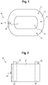
- FIGS. 1 and 2 show a protective dressing set for DP catheter, comprising a dressing (10) and a holding device (20) in the form of a pouch (21).
- this set consists of only two distinct elements, namely the dressing (10) and the holding device (20). This greatly facilitates his manipulations.
- the set is convenient to use and has a reduced cost compared to more complex sets.
- the dressing (10) is designed to protect an emergence point of the DP catheter coming out of a patient's belly.
- the window dressing (10) is waterproof and breathable.
- the dressing (10) comprises an outer layer (11) impervious and transparent, an inner layer (12) opaque (or transparent) shaped frame and a protective paper (13) removable covering an inner face (15) of the inner layer (12), opposite the outer layer (11).
- the layer (12) delimits a central window (14), which is covered by the transparent non-adhesive layer (11) and makes it possible to see through the dressing (10).
- the dimensions of the window (14) are for example of the order of 8cm x 4cm, but may vary depending on the patient.
- the window (14) is devoid of adhesive material.
- the transparent window (14) provides medical monitoring of the point of emergence of the catheter emerging from the patient's skin.
- the pouch (21) allows to hide the window (14), and thus prevent the patient to visualize this point of emergence for increased discretion, security and comfort.
- the inner face (15) of the layer (12) is adhesive, to fix the dressing (10) against the skin of the patient. Initially, the face (15) is covered by the protective paper (13), which is removable to reveal the inner face (15) and stick the dressing (10).
- the bonding area of the face (15) is limited to the shape of the frame of the layer (12), around the window (14). Thus, the bonding area is reduced to a minimum, which limits the use of glue that could cause an unpleasant or harmful allergic reaction in the patient.
- the glue used is the most hypoallergenic possible and / or uses a coating technique to reduce its harmfulness.
- the use of silicone or PSA silicone coatings can be envisaged, for example in the form of a gel.
- the outer layer (11) is polyurethane (transparent), while the inner layer (12) is nonwoven material (opaque) or polyurethane (transparent).
- the layers (11, 12) may be of other materials adapted to the intended application.
- the dressing (10) must be breathable so as not to macerate against the skin of the patient.
- at least one of the layers (11, 12) is perforated (or very breathable porous material), to improve the breathability and flexibility of the dressing (10).
- the dressing (10) in the case of the DP has a notch (16) side for the passage and sealing of the tube of the DP catheter.
- the notch (16) is formed through the two layers (11, 12).
- the notch (16) may be in the form of a "keyhole", with a rounded portion (17) for the passage of the tube and a thinned portion (18) intended to be tightened around the tube.
- the holding device (20) is adapted to hold the catheter (3) close to the dressing (10), preferably against the dressing (10).
- the device (20) comprises a pouch (21) consisting of two parts delimiting between them a receiving space of the catheter. Preferably, these two parts are impervious. Still preferably, the pouch (21) is opaque and white in color. This makes it possible to mask the tube (4) and the connector (5) of the catheter (3) housed in the pouch (21).
- the pocket (21) is provided with an opening (22) on at least one side, preferably a single opening (22) on one side, or two openings (22) on opposite sides.
- the dimensions of the pouch (21) are preferably between 7cm x 3cm and 15cm x 20cm, preferably of the order of 12cm x 7.5cm or 16cm x 7cm. Such dimensions allow the pocket (21) to hide the window (14), regardless of the positioning of the dressing (10).
- One side of the pouch (21) is provided with two parallel double-sided adhesive strips (23, 24) for attachment to the dressing (10).
- Each strip (23, 24) has a face secured to the pocket (21) and a tacky face opposite to the cover (21).
- the tacky side is provided with a removable protective paper (25, 26). Once the protective paper (25, 26) is removed, the tacky face can be applied to the dressing (10) to attach the pocket (21).
- the protective papers (25, 26) of the adhesive strips (23, 24) may protrude on one side of the pouch (21) different from the opening (22), to facilitate their grasping by the patient.
- the figure 3 shows the DP catheter (3) emerging from the patient's abdomen (7) at an emergence point (6).
- the catheter (3) comprises a tube (4) exiting the belly (7) and an external connector (5) for connecting the catheter to a glucose solution bag placed or suspended on a dialysis machine.
- the connector (5) is adapted to receive another tube to connect the catheter tube (4) to the bag.
- the Figures 4 to 6 show the dressing set (1) fitted to the patient.
- the dressing (10) is glued on the belly (7) by its inner face (15) adhesive.
- the window (14) is centered on the point of emergence (6), not visible under the pocket (21).
- the tube (4) extends on the side of the dressing (10) and exits through the notch (16), more precisely by the rounded portion (17), while the thinned portion (18) is tightened around the tube ( 4). This ensures the impermeability of the dressing (10) against the skin of the belly (7) at the outlet of the tube (4).
- the pouch (21) is glued to the outer layer (11) of the dressing (10) via the adhesive strips (23, 24). The pouch (21) then covers the window (14), which makes it possible to hide the point of emergence (6) to the patient.
- the connector (5) and the tube (4) of the catheter (3) can be easily slid into the pouch (21) by the patient so as to hold them against the dressing (10) without causing discomfort.
- the weight of the catheter (3) is distributed over the entire internal volume of the pouch (21). When a new dialysis operation is to be performed, the patient can easily remove the connector (5) and the tube (4) from the pouch (21).
- the catheter (3) can be maintained simply and conveniently on the patient's stomach, without generating additional bonding surface against the skin.
- the figure 7 shows a person slightly lifting the pocket (21), which allows him to see through the window (14). This person may be the patient or a member of the nursing staff. This makes it possible to verify that no infection has developed at the point of emergence (6) of the catheter (3).
- the figure 8 shows a second embodiment of a dressing set (1) according to the invention. Certain elements constituting the set (1) are comparable to those of the first embodiment described above and, for the sake of simplification, bear the same numerical references.
- the set (1) comprises a dressing (10) and a holding device (30), in the form of a strip (31) provided with two ends (33) adhesive and a central portion (34) non-adhesive.
- the connector (5) and the tube (4) of the catheter (3) can be easily attached to the dressing (10) by the patient, so as to hold them against the dressing (10) without causing embarrassment.
- the patient can easily detach the connector (5).
- the catheter (3) can be maintained simply and conveniently on the patient's stomach, without generating additional bonding surface against the skin.
- the figure 9 shows a variant of the figure 8 in which the holding device (30) comprises two strips (31).
- a strip (31) is used to hold the tube (4), while the second strip (31) is used to hold the connector (5).
- the dressing set (1) may comprise a plurality of dressings (10) and strips (31), so that the patient can use the required number of strips (31) with each dressing (10), depending on the length of the tube ( 4).
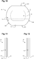
- the Figures 10 and 11 show a variant of the dressing (10) Figures 1 to 6 .
- the figure 10 is a front view, while the figure 11 is a sectional view of the dressing (10).
- the dressing (10) consists of an outer layer (11) of polyurethane bonded to a layer (12) of nonwoven fabric.
- the polyurethane layer (11) is 25 ⁇ m thick.
- the inner face (15) of the layer (12) is adhesive, for fixing the dressing (10) against the skin of the patient or on the pocket (21). Initially, the face (15) is covered by the protective paper (13), which is removable to reveal the inner face (15) and stick the dressing (10).
- the bonding area of the face (15) is limited to the shape of the frame of the layer (12), around the window (14).
- the dimensions of the dressing (10) are 14cm x 12cm, while the dimensions of the window (14) are 9cm x 6cm.
- the dressing (10) has a particular geometry, ensuring its resistance to delamination.
- the dressing (10) has two straight sides (101) and two rounded sides (102), two by two opposite, and separated by four corners (103).
- the rounded sides (102) have a radius of curvature of 7.25cm, while the corners (103) have a radius of curvature of 0.1cm.
- the figure 12 is a variant of the figure 11 wherein the dressing (10) comprises two layers (11, 12) of polyurethane.
- the inner layer (12) is perforated to provide breathability of the dressing (10).
- the inner layer (12) is perforated by 20 to 40%, for example about 30%, of the surface bordering the central window (14).
- the perforations have a diameter of 2.8 mm each.
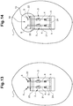
- FIGS. 13 and 14 show a variant of a dressing set (1) according to the invention, in the case of a hemodialysis (HD).
- the hemodialysis catheter (3) comprises one or two tubes (4) emerging from the pectoral (7) of the patient at one or two point (s) of emergence (s) (6).
- the catheter (3) also comprises one or two external connector (s) (5) provided with clamps.
- the external connector (s) (5) will be connected during the hemodialysis session to a dialysis generator and a filter (hemodialyzer) in order to extract the blood from the patient and ensure its purification, during a session of 4 hours on average.
- the dressing set (1) comprises a pouch (21) fixed at the top of the patient's skin, and a dressing (10) partially covering the pouch (21).
- the dressing (10) covers the opening (22) and preferably at least 4cm in the upper part of the pouch (21).
- the dressing (10) seals with the patient's skin on the edges of the pouch (21).
- the rear face of the pouch (21) is equipped with adhesive strips (23, 24) double-sided, respectively in the upper part and in the lower part.
- the upper strip (23) makes it possible to stick the pouch (21) on the skin of the patient.
- the lower strip (24) can be used to adjust the length of the pouch (21) to the length of the tubes (4) and connectors (5), by folding the pouch (21) on itself.
- the window dressing (10) has no lateral notch.
- the viewing window (14) of the dressing (10) may be obscured by a compress, not shown on the figure 14 for the sake of simplification.
- the compress prevents the patient to visualize the emergence points (6), which could interfere with his body image.
- the dressing set (1) may be shaped differently from the Figures 1 to 14 without departing from the scope of the invention, defined by the claims.
- the dressing (10) may be free of protective paper (13), while the inner layer (12) has a non-adhesive inner face (15) adapted to receive an application of adhesive material.
- the dressing set (1) may include a tube or a pot of glue. The patient himself applies the glue on the layer (12) around the window (14), in other words on the internal face (15) in the form of a frame.
- the pouch (21) and the dressing (10) are provided with a system with loops and hooks, for attaching the pouch (21) to the dressing (10).
- the pouch (21) is devoid of dressing attachment system (10).
- the patient can himself apply glue on the bag (21) to fix it to the dressing (10).
- the dressing (10) may comprise a plurality of lateral notches (16), in particular on different sides, instead of a single lateral notch (16) on one side.
- the dressing set (1) can be adapted in terms of cost, ergonomics, functionality and performance.
Abstract
Description
- La présente invention concerne le domaine technique des dispositifs de maintien ou de fixation et de protection des cathéters, notamment les cathéters de dialyse péritonéale ou d'hémodialyse (protection par pansements imperméables et respirants). L'invention pourrait également s'appliquer au maintien et à la protection d'autres dispositifs d'usage médical, comme les sondes, drains ou autres tubes à maintenir et à protéger.
- Le cathéter de dialyse péritonéale se présente sous forme d'un tube en silicone transparent qui sort du bas ventre des patients, permettant le remplissage ou la vidange du péritoine des patients avec une solution glucosée, afin de permettre les échanges entre le sang et cette solution. Cela permet d'épurer le sang de ses toxines urémiques, ainsi que de l'eau en excès.
- Le cathéter d'hémodialyse se présente sous forme d'un ou deux tubes en silicone ou polyuréthane, sortant du thorax du patient au niveau de son pectoral, souvent après un trajet sous cutané (appelé tunellisation). Ce ou ces mêmes tubes entrent dans la veine jugulaire du patient et leurs extrémités descendent idéalement en limite de veine cave et d'oreillette. Ce système assure un accès au sang du patient, afin de procéder à son épuration lors des séances de dialyse.
- Actuellement, de nombreux centres de dialyse réalisent leur propre système de pansement protecteur des cathéters de dialyse péritonéale ou d'hémodialyse, sans faire appel à un produit fini, complet et proposé dans un set de soin stérile. Par conséquent, il existe autant de protocoles que de centres de dialyse.
- Le problème principal de la dialyse est la chronicité des patients, car ils sont traités à vie, sauf transplantation. Egalement, les habitudes du personnel soignant sont difficiles à changer.
- Les patients en dialyse péritonéale (DP) ou en hémodialyse (HD) ont la plupart du temps des pansements collés à la peau 24h/24, ce qui va très souvent entraîner des réactions cutanées et allergies aux colles des adhésifs utilisés. Les dispositifs proposés actuellement ne permettent pas de résoudre toutes les allergies, tout en conservant une puissance de collage suffisante. En particulier, les enduits silicone permettent de résoudre les allergies, mais ne tiennent pas suffisamment collés à la peau.
- Pour ces patients en DP ou HD, le point d'émergence de leur cathéter à travers la peau doit respirer afin d'éviter la macération, qui pourrait engendrer un risque infectieux.
-
WO2015/166157 décrit un set de pansement protecteur pour cathéter, comprenant une pièce en non tissé ou en mousse prévue pour être disposée au point d'émergence du cathéter, un fourreau prévu pour recevoir le tube du cathéter, et un pansement prévu pour recouvrir la pièce et l'ouverture supérieure du fourreau. - Ce set comprenant trois éléments distincts est relativement coûteux à fabriquer et complexe à mettre en oeuvre, nécessitant plusieurs manipulations par le patient ou le personnel médical.
- Ainsi, il existe un réel besoin de proposer un set de pansement permettant de protéger le point d'émergence du cathéter, et maintenir le connecteur externe du cathéter à proximité du pansement.
- Dans le même temps, il est important de réduire le risque d'allergies, soit en réduisant les zones de collage, soit en faisant appel à des composants techniques répondant à cette problématique.
- Actuellement, de nombreux patients sont forcés de se débrouiller avec leurs propres astuces (ceinture, pochette en tissu, gant de toilette...). Dans certains cas, en l'absence de solution adéquate ou faute de moyens financiers, les patients n'utilisent aucun pansement, ce qui est susceptible d'entrainer des risques importants pour leur santé.
- Le but de la présente invention est de proposer un set de pansement amélioré, remédiant aux problèmes ci-dessus.
- A cet effet, l'invention a pour objet un set de pansement protecteur pour cathéter, comprenant :
- un pansement imperméable et respirant, conçu pour protéger un point d'émergence du cathéter, et comportant une fenêtre de visualisation du point d'émergence ; et
- un dispositif de maintien d'un connecteur externe du cathéter à proximité du pansement.
- Ainsi, l'invention permet de maintenir le cathéter de manière simple et pratique sur l'abdomen ou le thorax du patient, sans le gêner. L'invention est peu coûteuse à fabriquer et simple à utiliser.
- L'invention évite que le cathéter ne se déplace dans les sous-vêtements ou vêtements du patient, et réduit donc le risque infectieux (péritonite ou endocardite). Le cathéter reste facilement accessible au patient, pour réaliser ses échanges (vider et remplir son ventre de solution glucosée) plusieurs fois par jour dans le cas DP.
- La fenêtre de visualisation permet une surveillance médicale du point d'émergence du cathéter sortant de la peau du patient, ce qui permettra de traiter immédiatement tout début d'inflammation ou d'infection. De préférence, le dispositif de maintien permet d'occulter la fenêtre dans le cas DP, ou une compresse peut remplir ce rôle dans le cas HD, et ainsi empêcher le patient de visualiser ce point d'émergence, ce qui pourrait le gêner pour son image corporelle.
- Le dispositif de maintien peut être fixé directement au pansement protégeant le point d'émergence, ce qui limite la zone de collage sur la peau. En alternative, le dispositif de maintien (de type pochette) peut être fixé directement à la peau du patient, puis être en partie recouvert par le pansement fenêtré.
- Le pansement peut être changé de façon quotidienne ou tous les deux jours. Il doit donc être facile à réaliser, en respectant l'ensemble des règles d'aseptie afin de garantir une hygiène maximale. Le pansement est imperméable, pour permettre au patient de prendre une douche sans exposer le point d'émergence du cathéter à l'eau, ce qui pourrait lui faire courir un risque infectieux.
- Le set de pansement selon l'invention peut être proposé à un coût raisonnable, dans un contexte où le remboursement des séances de dialyse ne cesse de baisser depuis plusieurs années.
- Selon d'autres caractéristiques avantageuses de l'invention, prises isolément ou en combinaison :
- Le set est constitué d'un pansement et d'un dispositif de maintien.
- Le pansement est de préférence fenêtré.
- Le dispositif de maintien est de type bandelettes ou pochette.
- Le pansement et le dispositif de maintien sont deux éléments distincts.
- Le pansement et le dispositif de maintien sont solidarisés de manière amovible et non permanente.
- Le dispositif de maintien comprend une pochette pourvue d'une ouverture sur au moins un côté.
- La pochette comprend une unique ouverture.
- La pochette est munie d'un système de fixation au pansement ou à la peau du patient
- Le système de fixation comprend au moins une bande adhésive équipant la pochette et prévue pour venir se fixer sur le pansement ou sur la peau.
- La bande adhésive comporte un papier protecteur, dépassant sur au moins un côté de la pochette pour faciliter sa saisie.
- Le papier protecteur est constitué de papier siliconé.
- La bande adhésive est double-face.
- La bande adhésive comporte une colle acrylique sur ses deux faces.
- Le système de fixation comprend au moins une bande à boucles ou crochets équipant la pochette, et prévue pour venir se fixer sur une bande à crochets ou boucles complémentaire équipant le pansement.
- Le système de fixation comprend deux bandes, de préférence parallèles, équipant la pochette.
- La pochette est opaque.
- La pochette est réalisée en polyéthylène, viscose et/ou polyester (préférentiellement sous forme de film).
- La pochette mesure entre 3 et 15 cm de large par 7 à 20 cm de longueur, de préférence 7 cm de large sur 16 cm de longueur.
- La pochette comporte deux parois en vis-à-vis et une liaison latérale reliant ces deux parois.
- La liaison latérale est une soudure ou une couture.
- La liaison est respirante.
- La liaison est réalisée manuellement.
- La pochette est respirante et imperméable.
- La pochette disposée sur le pansement occulte la fenêtre de visualisation du point d'émergence (cas DP).
- Le pansement fenêtré recouvrant au moins partiellement la pochette occulte l'ouverture recevant le tube et le connecteur externe du cathéter (cas HD).
- Le dispositif de maintien comprend au moins une bandelette pourvue de deux extrémités adhésives et d'une partie centrale non-adhésive (cas DP).
- Le dispositif de maintien comprend plusieurs bandelettes (cas DP).
- Le dispositif de maintien est constitué d'une ou plusieurs bandelettes, chacune pourvue de deux extrémités adhésives et d'une partie centrale non-adhésive (cas DP).
- La bandelette comprend une unique partie non-adhésive, et non plusieurs parties non-adhésives réparties sur sa longueur (cas DP).
- Le pansement fenêtré comporte au moins une encoche latérale pour le passage et le maintien imperméable du tube du cathéter (cas DP).
- L'encoche latérale comprend une portion arrondie pour le passage du tube et une portion amincie prévue pour être resserrée autour du tube (cas DP).
- Le pansement fenêtré comprend : une couche externe transparente ; et une couche interne en forme de cadre délimitant la fenêtre de visualisation.
- La couche interne comporte une face interne adhésive, et le pansement comprend un dispositif couvrant la face interne adhésive et amovible pour appliquer la face interne adhésive contre la peau du patient.
- La couche interne comporte une face interne non-adhésive, apte à recevoir une application de matière adhésive.
- La couche externe est en polyuréthane.
- La couche interne est en matériau non-tissé
- La couche interne est en polyuréthane.
- Lorsque les couches interne et externe sont réalisées en polyuréthane, la couche interne est perforée.
- Lorsque les couches interne et externe sont réalisées en polyuréthane, la couche interne est perforée sur 20 à 40%, de préférence environ 30%, de la surface bordant la fenêtre centrale et où le polyuréthane est double.
- Les perforations ont un diamètre de 2,8 mm chacune.
- Le pansement fenêtré est réalisé en polyuréthane, émulsion acrylique, papier siliconé, viscose et/ou polyamide.
- Le pansement fenêtré a une couche de polyuréthane ayant une épaisseur de 25 µm.
- Le pansement fenêtré peut être enduit d'un adhésif du type gel silicone. De préférence, le gel silicone a une densité de 150 g/m2.
- Le pansement fenêtré peut aussi être enduit d'un adhésif du type colle acrylique.
- Afin d'éviter une dégradation prématurée des propriétés adhésives du gel silicone ou de la colle acrylique, des bandes anti-adhésives de papier siliconé sont disposées au-dessus de la couche d'adhésif, par exemple en polyéthylène ou PET transparent.
- Le pansement fenêtré mesure entre 8x8 cm et 16x16 cm, de préférence 12 cm de largeur sur 14 cm de longueur.
- La quantité d'eau évacuée pendant 24h par le pansement est strictement supérieure à 1500 g/m2.
- Le pansement est stérilisé selon les normes ISO 11135 et ISO 10993-7.
- Le pansement est dépourvu de latex, de phtalates, de bisphénols, de dérivés d'origine animale. Il est donc biocompatible.
- L'invention sera mieux comprise à la lecture de la description qui va suivre, donnée uniquement à titre d'exemple non limitatif et faite en référence aux dessins annexés sur lesquels :
- les
figures 1 et 2 sont des vues de face, respectivement d'un pansement et d'un dispositif de maintien sous forme de pochette, formant un set de pansement conforme à un premier mode de réalisation de l'invention ; - la
figure 3 est une vue de face du ventre d'un patient traité par dialyse péritonéale, avec un point d'émergence d'un cathéter ; - la
figure 4 est une vue analogue à lafigure 3 , montrant le ventre du patient équipé du set de pansement desfigures 1 et 2 ; - la
figure 5 est une vue à plus grande échelle du détail V à lafigure 4 , montrant le passage et le maintien imperméable du tube du cathéter dans une encoche latérale du pansement ; - la
figure 6 est une vue analogue à lafigure 4 , montrant le cathéter maintenu dans la pochette ; - la
figure 7 est une vue en perspective du ventre et du set de pansement, lorsque la pochette est soulevée pour voir le point d'émergence du cathéter à travers la fenêtre du pansement ; - la
figure 8 est une vue de face du ventre d'un patient ayant subi une dialyse péritonéale, équipé d'un set de pansement conforme à un deuxième mode de réalisation de l'invention ; - la
figure 9 est une vue analogue à lafigure 8 , montrant une variante du deuxième mode de réalisation ; - la
figure 10 est une vue analogue à lafigure 1 , montrant un pansement conforme à un troisième mode de réalisation de l'invention, dépourvu d'encoche pour le passage de la tubulure ; - la
figure 11 est une vue partielle de côté, et à plus grande échelle, centrée sur le détail XI, du pansement de lafigure 10 ; - la
figure 12 est une vue analogue à lafigure 11 , montrant un pansement conforme à un quatrième mode de réalisation de l'invention ; - les
figures 13 et 14 sont des vues analogues auxfigures 3 et 4 , montrant un set de pansement conforme à un cinquième mode de réalisation de l'invention. - La description ci-après fait référence aux manipulations du patient dans le cadre de la DP, étant entendu que les mêmes manipulations pourraient être effectuées par le personnel soignant ou par un proche, et nécessairement par un personnel soignant lors de l'HD.
- Les
figures 1 et 2 montrent un set de pansement protecteur de cathéter pour DP, comprenant un pansement (10) et un dispositif de maintien (20) se présentant sous forme de pochette (21). - De manière avantageuse, ce set est constitué de seulement deux éléments distincts, à savoir le pansement (10) et le dispositif de maintien (20). Cela facilite grandement ses manipulations. Le set est pratique à utiliser et présente un coût réduit, en comparaison avec des sets plus complexes.
- Le pansement (10) est conçu pour protéger un point d'émergence du cathéter DP sortant du ventre d'un patient. Le pansement fenêtré (10) est imperméable et respirant.
- Le pansement (10) comprend une couche externe (11) imperméable et transparente, une couche interne (12) opaque (ou transparente) en forme de cadre et un papier protecteur (13) amovible recouvrant une face interne (15) de la couche interne (12), à l'opposé de la couche externe (11).
- La couche (12) délimite une fenêtre centrale (14), qui est recouverte par la couche (11) transparente non adhésive et permet de voir à travers le pansement (10). Les dimensions de la fenêtre (14) sont par exemple de l'ordre de 8cm x 4cm, mais peuvent varier en fonction du patient. La fenêtre (14) est dépourvue de matière adhésive. La fenêtre (14) transparente permet une surveillance médicale du point d'émergence du cathéter qui sort de la peau du patient. La pochette (21) permet d'occulter la fenêtre (14), et ainsi empêcher le patient de visualiser ce point d'émergence, pour une discrétion, une sécurité et un confort accrus.
- La face interne (15) de la couche (12) est adhésive, pour fixer le pansement (10) contre la peau du patient. Initialement, la face (15) est recouverte par le papier protecteur (13), qui est amovible pour découvrir la face interne (15) et coller le pansement (10). La zone de collage de la face (15) est limitée à la forme du cadre de la couche (12), autour de la fenêtre (14). Ainsi, la zone de collage est réduite au maximum, ce qui permet de limiter l'utilisation de colle qui pourrait provoquer une réaction allergique désagréable ou nocive chez le patient. La colle utilisée est la plus hypoallergénique possible et/ou fait appel à une technique d'enduction permettant de réduire sa nocivité. L'utilisation d'enduits silicones ou PSA silicones est envisageable, par exemple sous forme de gel.
- De préférence, la couche externe (11) est en polyuréthane (transparent), tandis que la couche interne (12) est en matériau non-tissé (opaque) ou en polyuréthane (transparent). En alternative, les couches (11, 12) peuvent être en d'autres matériaux adaptés à l'application visée. Le pansement (10) doit être respirant pour ne pas entraîner de macération contre la peau du patient. De préférence, au moins l'une des couches (11, 12) est perforée (ou en matière poreuse très respirante), pour améliorer la respirabilité et la flexibilité du pansement (10).
- Le pansement (10) dans le cas de la DP comporte une encoche (16) latérale pour le passage et le maintien étanche du tube du cathéter de DP. L'encoche (16) est formée à travers les deux couches (11, 12). L'encoche (16) peut être en forme de « trou de serrure », avec une portion arrondie (17) pour le passage du tube et une portion amincie (18) prévue pour être resserrée autour du tube.
- Le dispositif de maintien (20) est conçu pour maintenir le cathéter (3) à proximité du pansement (10), de préférence contre le pansement (10).
- Le dispositif (20) comprend une pochette (21) constituée de deux parties délimitant entre elles un espace de réception du cathéter. De préférence, ces deux parties sont imperméables. Encore de préférence, la pochette (21) est opaque et de couleur blanche. Cela permet de masquer le tube (4) et le connecteur (5) du cathéter (3) logé dans la pochette (21).
- La pochette (21) est pourvue d'une ouverture (22) sur au moins un côté, de préférence une unique ouverture (22) sur un côté, ou bien deux ouvertures (22) sur des côtés opposés.
- Les dimensions de la pochette (21) sont de préférence comprises entre 7cm x 3cm et 15cm x 20cm, encore de préférence de l'ordre de 12cm x 7,5cm ou 16cm x 7cm. De telles dimensions permettent à la pochette (21) d'occulter la fenêtre (14), quel que soit le positionnement du pansement (10).
- Une face de la pochette (21) est munie de deux bandes adhésives (23, 24) doubles faces parallèles, pour sa fixation au pansement (10). Chaque bande (23, 24) comporte une face solidaire de la pochette (21) et une face collante opposée à la pochette (21). La face collante est munie d'un papier protecteur (25, 26) amovible. Une fois le papier protecteur (25, 26) retiré, la face collante peut être appliquée sur le pansement (10) pour y fixer la pochette (21).
- Avantageusement, les papiers protecteurs (25, 26) des bandes adhésives (23, 24) peuvent dépasser sur un côté de la pochette (21) différent de l'ouverture (22), pour faciliter leur saisie par le patient.
- La
figure 3 montre le cathéter de DP (3) sortant du ventre (7) du patient à un point d'émergence (6). Le cathéter (3) comprend un tube (4) sortant du ventre (7) et un connecteur externe (5) pour connecter le cathéter à une poche de solution glucosée posée ou suspendue sur un appareil de dialyse. Le connecteur (5) est conçu pour recevoir un autre tube, afin de relier le tube (4) de cathéter (3) à la poche. - Les
figures 4 à 6 montrent le set de pansement (1) équipant le patient. Le pansement (10) est collé sur le ventre (7) par sa face interne (15) adhésive. La fenêtre (14) est centrée sur le point d'émergence (6), non visibles sous la pochette (21). - Le tube (4) s'étend sur le côté du pansement (10) et ressort par l'encoche (16), plus précisément par la portion arrondie (17), tandis que la portion amincie (18) est resserrée autour du tube (4). Cela permet de garantir l'imperméabilité du pansement (10) contre la peau du ventre (7) à la sortie du tube (4).
- La pochette (21) est collée sur la couche externe (11) du pansement (10) via les bandes adhésives (23, 24). La pochette (21) recouvre alors la fenêtre (14), ce qui permet de masquer le point d'émergence (6) au patient.
- Le connecteur (5) et le tube (4) du cathéter (3) peuvent être facilement glissés dans la pochette (21) par le patient, de manière à les maintenir contre le pansement (10) sans provoquer de gêne. Le poids du cathéter (3) est réparti sur tout le volume interne de la pochette (21). Lorsqu'une nouvelle opération de dialyse doit être effectuée, le patient peut facilement sortir le connecteur (5) et le tube (4) hors de la pochette (21).
- Ainsi, le cathéter (3) peut être maintenu de manière simple et pratique sur le ventre du patient, sans engendrer de surface de collage supplémentaire contre la peau.
- La
figure 7 montre une personne soulevant légèrement la pochette (21), ce qui lui permet de voir à travers la fenêtre (14). Cette personne peut être le patient ou un membre du personnel soignant. Cela permet de vérifier qu'aucune infection ne s'est développée au niveau du point d'émergence (6) du cathéter (3). - La
figure 8 montre un deuxième mode de réalisation d'un set de pansement (1) conforme à l'invention. Certains éléments constitutifs du set (1) sont comparables à ceux du premier mode de réalisation décrit plus haut et, dans un but de simplification, portent les mêmes références numériques. - Le set (1) comprend un pansement (10) et un dispositif de maintien (30), sous forme de bandelette (31) pourvue de deux extrémités (33) adhésives et d'une partie centrale (34) non-adhésive.
- Grâce à la bandelette (31), le connecteur (5) et le tube (4) du cathéter (3) peuvent être facilement fixés au pansement (10) par le patient, de manière à les maintenir contre le pansement (10) sans provoquer de gêne. Lorsqu'une nouvelle opération de dialyse doit être effectuée, le patient peut facilement détacher le connecteur (5).
- Ainsi, le cathéter (3) peut être maintenu de manière simple et pratique sur le ventre du patient, sans engendrer de surface de collage supplémentaire contre la peau.
- La
figure 9 montre une variante de lafigure 8 , dans laquelle le dispositif de maintien (30) comprend deux bandelettes (31). Une bandelette (31) est utilisée pour tenir le tube (4), tandis que la seconde bandelette (31) est utilisée pour tenir le connecteur (5). Le set de pansement (1) peut comprendre plusieurs pansements (10) et bandelettes (31), de sorte que le patient peut utiliser le nombre requis de bandelettes (31) avec chaque pansement (10), en fonction de la longueur du tube (4). - Les
figures 10 et 11 montrent une variante du pansement (10) desfigures 1 à 6 . Lafigure 10 est une vue de face, tandis que lafigure 11 est une vue en coupe du pansement (10). Le pansement (10) est constitué d'une couche externe (11) en polyuréthane collée à une couche (12) en non-tissé. De préférence, la couche (11) en polyuréthane mesure 25 µm d'épaisseur. - La face interne (15) de la couche (12) est adhésive, pour fixer le pansement (10) contre la peau du patient ou sur la pochette (21). Initialement, la face (15) est recouverte par le papier protecteur (13), qui est amovible pour découvrir la face interne (15) et coller le pansement (10). La zone de collage de la face (15) est limitée à la forme du cadre de la couche (12), autour de la fenêtre (14).
- Les dimensions du pansement (10) sont 14cm x 12cm, tandis que les dimensions de la fenêtre (14) sont 9cm x 6cm. Le pansement (10) a une géométrie particulière, assurant sa résistance au décollement. Le pansement (10) a deux côtés droits (101) et deux côtés arrondis (102), deux à deux opposés, et séparés par quatre coins (103). Les côtés arrondis (102) ont un rayon de courbure de 7,25cm, tandis que les coins (103) ont un rayon de courbure de 0,1cm.
- La
figure 12 est une variante de lafigure 11 , où le pansement (10) comprend deux couches (11, 12) en polyuréthane. La couche interne (12) est perforée pour assurer la respirabilité du pansement (10). De préférence, la couche interne (12) est perforée sur 20 à 40%, par exemple environ 30%, de la surface bordant la fenêtre centrale (14). Encore de préférence, les perforations ont un diamètre de 2,8 mm chacune. - Les
figures 13 et 14 montrent une variante d'un set de pansement (1) conforme à l'invention, dans le cas d'une hémodialyse (HD). - Le cathéter d'hémodialyse (3) comprend un ou deux tubes (4) sortant du pectoral (7) du patient à un ou deux point(s) d'émergence(s) (6). Le cathéter (3) comprend également un ou deux connecteur(s) externe(s) (5) munis de clamps. Le(s) connecteur(s) externe(s) (5) seront reliés durant la séance d'hémodialyse à un générateur de dialyse et un filtre (hémodialyseur) afin d'extraire le sang du patient et en assurer l'épuration, durant une séance de 4h en moyenne.
- Le set de pansement (1) comprend une pochette (21) fixée en partie haute sur la peau du patient, et un pansement (10) recouvrant partiellement la pochette (21). En particulier, le pansement (10) recouvre l'ouverture (22) et de préférence au moins 4cm en partie supérieure de la pochette (21). Le pansement (10) assure l'étanchéité avec la peau du patient sur les bords de la pochette (21).
- La face arrière de la pochette (21) est équipée de bandelettes (23, 24) adhésives double face, respectivement en partie supérieure et en partie inférieure. La bandelette supérieure (23) permet de coller la pochette (21) sur la peau du patient. La bandelette inférieure (24) peut être utilisée pour ajuster la longueur de la pochette (21) à la longueur des tubes (4) et connecteurs (5), en repliant la pochette (21) sur elle-même.
- Dans le cas HP, le pansement fenêtré (10) est dépourvu d'encoche latérale. La fenêtre de visualisation (14) du pansement (10) peut être occultée par une compresse, non représentée sur la
figure 14 dans un but de simplification. Ainsi, la compresse empêche le patient de visualiser les points d'émergence (6), ce qui pourrait le gêner pour son image corporelle. - Par ailleurs, le set de pansement (1) peut être conformé différemment des
figures 1 à 14 sans sortir du cadre de l'invention, définie par les revendications. - En variante non représentée, le pansement (10) peut être dépourvu de papier protecteur (13), tandis que la couche interne (12) comporte une face interne (15) non-adhésive, apte à recevoir une application de matière adhésive. Dans ce cas, le set de pansement (1) peut inclure un tube ou un pot de colle. Le patient applique lui-même la colle sur la couche (12) autour de la fenêtre (14), autrement dit sur la face interne (15) en forme de cadre.
- Selon une autre variante non représentée, la pochette (21) et le pansement (10) sont munis d'un système à boucles et crochets, permettant de fixer la pochette (21) au pansement (10).
- Selon une autre variante non représentée, la pochette (21) est dépourvue de système de fixation au pansement (10). Le patient peut appliquer lui-même de la colle sur la pochette (21) pour la fixer au pansement (10).
- Selon une autre variante non représentée, le pansement (10) peut comporter plusieurs encoches latérales (16), notamment sur différents côtés, au lieu d'une unique encoche latérale (16) sur un seul côté.
- En outre, les caractéristiques techniques des différents modes de réalisation et variantes mentionnés ci-dessus peuvent être, en totalité ou pour certaines d'entre elles, combinées entre elles.
- Ainsi, le set de pansement (1) peut être adapté en termes de coût, d'ergonomie, de fonctionnalités et de performance.
Claims (15)
- Set (1) de pansement protecteur pour cathéter (3), comprenant :- un pansement (10) imperméable et respirant, conçu pour protéger un point d'émergence (6) du cathéter (3), et comportant une fenêtre (14) de visualisation du point d'émergence (6) ; et- un dispositif de maintien (20 ; 30) d'un connecteur externe (5) du cathéter (3) à proximité du pansement (10).
- Set (1) selon la revendication 1, caractérisé en ce que le dispositif de maintien (20) comprend une pochette (21) pourvue d'une ouverture (22) sur au moins un côté.
- Set (1) selon la revendication 2, caractérisé en ce que la pochette (21) est munie d'un système de fixation au pansement (10) ou à la peau du patient.
- Set (1) selon la revendication 3, caractérisé en ce que le système comprend au moins une bande adhésive (23 ; 23, 24).
- Set (1) selon la revendication 4, caractérisé en ce que l'au moins une bande adhésive (23 ; 23, 24) comporte un papier protecteur (25 ; 25, 26) dépassant sur au moins un côté de la pochette (21) pour faciliter sa saisie par un patient.
- Set (1) selon l'une des revendications 2 à 5, caractérisé en ce que la pochette (21) est opaque.
- Set (1) selon la revendication 6, caractérisé en ce que la pochette (21) disposée sur le pansement (10) occulte la fenêtre (14) de visualisation du point d'émergence (6).
- Set (1) selon l'une des revendications 2 à 6, caractérisé en ce que le pansement (10) recouvrant au moins partiellement la pochette (21) occulte l'ouverture (22) recevant le tube (4) et le connecteur externe (5) du cathéter (3).
- Set (1) selon la revendication 1, caractérisé en ce que le dispositif de maintien (30) est constitué d'une ou plusieurs bandelettes (31), chacune pourvue de deux extrémités (33) adhésives et d'une partie centrale (34) non-adhésive.
- Set (1) selon l'une des revendications précédentes, caractérisé en ce que le pansement (10) comporte une encoche (16) latérale pour le passage et le maintien imperméable du tube (4) du cathéter (3).
- Set (1) selon la revendication 10, caractérisé en ce que l'encoche (16) latérale comprend une portion arrondie (17) pour le passage du tube (4) et une portion amincie (18) prévue pour être resserrée autour du tube (4).
- Set (1) selon l'une des revendications précédentes, caractérisé en ce que le pansement (10) comprend :- une couche externe (11) transparente ; et- une couche interne (12) en forme de cadre délimitant la fenêtre (14) de visualisation.
- Set (1) selon la revendication 12, caractérisé en ce que la couche externe (11) est en polyuréthane.
- Set (1) selon l'une des revendications 12 ou 13, caractérisé en ce que la couche interne (12) est en polyuréthane.
- Set (1) selon l'une des revendications 12 ou 13, caractérisé en ce que la couche interne (12) est en matériau non-tissé.
Applications Claiming Priority (1)
| Application Number | Priority Date | Filing Date | Title |
|---|---|---|---|
| FR1853470A FR3080272B1 (fr) | 2018-04-19 | 2018-04-19 | Set de pansement protecteur de catheter |
Publications (3)
| Publication Number | Publication Date |
|---|---|
| EP3556422A1 true EP3556422A1 (fr) | 2019-10-23 |
| EP3556422C0 EP3556422C0 (fr) | 2023-06-07 |
| EP3556422B1 EP3556422B1 (fr) | 2023-06-07 |
Family
ID=63080054
Family Applications (1)
| Application Number | Title | Priority Date | Filing Date |
|---|---|---|---|
| EP19170378.4A Active EP3556422B1 (fr) | 2018-04-19 | 2019-04-19 | Set de pansement protecteur de catheter |
Country Status (2)
| Country | Link |
|---|---|
| EP (1) | EP3556422B1 (fr) |
| FR (1) | FR3080272B1 (fr) |
Cited By (1)
| Publication number | Priority date | Publication date | Assignee | Title |
|---|---|---|---|---|
| CN111365534A (zh) * | 2020-03-13 | 2020-07-03 | 中国热带农业科学院农产品加工研究所 | 一种高分子涂层天然乳胶管及其制备方法 |
Citations (5)
| Publication number | Priority date | Publication date | Assignee | Title |
|---|---|---|---|---|
| US4669458A (en) * | 1980-03-10 | 1987-06-02 | Conmed Inc. | I.V. holder |
| WO1990001351A1 (fr) * | 1988-08-03 | 1990-02-22 | Kalt Medical Corp. | Pansements universels |
| WO2012161897A2 (fr) * | 2011-05-26 | 2012-11-29 | Carefusion 2200, Inc. | Système de pansement |
| WO2014039891A2 (fr) * | 2012-09-07 | 2014-03-13 | C. R. Bard, Inc. | Systèmes de fixation d'articles médicaux |
| WO2015166157A1 (fr) | 2014-04-30 | 2015-11-05 | Nephrokit | Dispositif de protection d'un catheter |
-
2018
- 2018-04-19 FR FR1853470A patent/FR3080272B1/fr active Active
-
2019
- 2019-04-19 EP EP19170378.4A patent/EP3556422B1/fr active Active
Patent Citations (5)
| Publication number | Priority date | Publication date | Assignee | Title |
|---|---|---|---|---|
| US4669458A (en) * | 1980-03-10 | 1987-06-02 | Conmed Inc. | I.V. holder |
| WO1990001351A1 (fr) * | 1988-08-03 | 1990-02-22 | Kalt Medical Corp. | Pansements universels |
| WO2012161897A2 (fr) * | 2011-05-26 | 2012-11-29 | Carefusion 2200, Inc. | Système de pansement |
| WO2014039891A2 (fr) * | 2012-09-07 | 2014-03-13 | C. R. Bard, Inc. | Systèmes de fixation d'articles médicaux |
| WO2015166157A1 (fr) | 2014-04-30 | 2015-11-05 | Nephrokit | Dispositif de protection d'un catheter |
Cited By (1)
| Publication number | Priority date | Publication date | Assignee | Title |
|---|---|---|---|---|
| CN111365534A (zh) * | 2020-03-13 | 2020-07-03 | 中国热带农业科学院农产品加工研究所 | 一种高分子涂层天然乳胶管及其制备方法 |
Also Published As
| Publication number | Publication date |
|---|---|
| EP3556422C0 (fr) | 2023-06-07 |
| FR3080272A1 (fr) | 2019-10-25 |
| EP3556422B1 (fr) | 2023-06-07 |
| FR3080272B1 (fr) | 2023-06-02 |
Similar Documents
| Publication | Publication Date | Title |
|---|---|---|
| FR2900817A1 (fr) | Bandage a usage medical pour un tube implante dans un patient, ainsi que le procede d'application de ce bandage sur la peau d'un patient | |
| CN104540485B (zh) | 一体式敷料装置 | |
| FR2881657A1 (fr) | Pansement de fixation et de protection d'aiguille | |
| US7658719B2 (en) | Bandage bag | |
| US20100294286A1 (en) | Flexible and leakproof and leak-resistant medical barriers and systems and methods of use thereof | |
| JP6497577B2 (ja) | 術後の乳房ドレッシング | |
| FR2932990A1 (fr) | Pansement de fixation et de protection d'aiguille. | |
| EP3556422B1 (fr) | Set de pansement protecteur de catheter | |
| JP2008183244A (ja) | カテーテル固定具 | |
| CN108113802A (zh) | 一种可分合的伤口及新生儿用护理装置 | |
| US20140046263A1 (en) | Protective shower guard for indwelling medical catheters | |
| WO2015140454A1 (fr) | Nécessaire pour le maintien et la protection de cathéters placés sur une zone du corps d'un patient | |
| WO2015166157A1 (fr) | Dispositif de protection d'un catheter | |
| RU2683395C1 (ru) | Устройство изолированной накладки в случае применения душа | |
| CN211327269U (zh) | 一种颈内静脉留置透析导管安全固定装置 | |
| EP2982355B1 (fr) | Pansement auto-adhésif | |
| EP3378451A1 (fr) | Pansement sanitaire | |
| CN220424277U (zh) | 一种肾科血液透析用透析导管保护套 | |
| CN209451031U (zh) | 一种透析用颈内静脉置管淋浴保护袋 | |
| FR3086529A1 (fr) | Procede de fabrication d'un dispositif adhesif destine a proteger un catheter implante chez un patient et dispositif adhesif obtenu | |
| CN215652003U (zh) | 一种腹膜透析患者用无菌保护贴膜 | |
| CN216222009U (zh) | 一种输液港拔针后专用敷料 | |
| CN211584363U (zh) | 抗疲劳眼贴 | |
| CN207949989U (zh) | 一种医用冷敷贴 | |
| CN205924256U (zh) | 婴幼儿关节保护带 |
Legal Events
| Date | Code | Title | Description |
|---|---|---|---|
| PUAI | Public reference made under article 153(3) epc to a published international application that has entered the european phase |
Free format text: ORIGINAL CODE: 0009012 |
|
| STAA | Information on the status of an ep patent application or granted ep patent |
Free format text: STATUS: THE APPLICATION HAS BEEN PUBLISHED |
|
| AK | Designated contracting states |
Kind code of ref document: A1 Designated state(s): AL AT BE BG CH CY CZ DE DK EE ES FI FR GB GR HR HU IE IS IT LI LT LU LV MC MK MT NL NO PL PT RO RS SE SI SK SM TR |
|
| AX | Request for extension of the european patent |
Extension state: BA ME |
|
| STAA | Information on the status of an ep patent application or granted ep patent |
Free format text: STATUS: REQUEST FOR EXAMINATION WAS MADE |
|
| 17P | Request for examination filed |
Effective date: 20200519 |
|
| RBV | Designated contracting states (corrected) |
Designated state(s): AL AT BE BG CH CY CZ DE DK EE ES FI FR GB GR HR HU IE IS IT LI LT LU LV MC MK MT NL NO PL PT RO RS SE SI SK SM TR |
|
| STAA | Information on the status of an ep patent application or granted ep patent |
Free format text: STATUS: EXAMINATION IS IN PROGRESS |
|
| 17Q | First examination report despatched |
Effective date: 20220330 |
|
| GRAP | Despatch of communication of intention to grant a patent |
Free format text: ORIGINAL CODE: EPIDOSNIGR1 |
|
| STAA | Information on the status of an ep patent application or granted ep patent |
Free format text: STATUS: GRANT OF PATENT IS INTENDED |
|
| RIC1 | Information provided on ipc code assigned before grant |
Ipc: A61F 13/00 20060101ALN20221102BHEP Ipc: A61M 25/02 20060101AFI20221102BHEP |
|
| INTG | Intention to grant announced |
Effective date: 20221117 |
|
| INTG | Intention to grant announced |
Effective date: 20221128 |
|
| GRAS | Grant fee paid |
Free format text: ORIGINAL CODE: EPIDOSNIGR3 |
|
| GRAA | (expected) grant |
Free format text: ORIGINAL CODE: 0009210 |
|
| STAA | Information on the status of an ep patent application or granted ep patent |
Free format text: STATUS: THE PATENT HAS BEEN GRANTED |
|
| AK | Designated contracting states |
Kind code of ref document: B1 Designated state(s): AL AT BE BG CH CY CZ DE DK EE ES FI FR GB GR HR HU IE IS IT LI LT LU LV MC MK MT NL NO PL PT RO RS SE SI SK SM TR |
|
| REG | Reference to a national code |
Ref country code: GB Ref legal event code: FG4D Free format text: NOT ENGLISH |
|
| REG | Reference to a national code |
Ref country code: CH Ref legal event code: EP Ref country code: AT Ref legal event code: REF Ref document number: 1573090 Country of ref document: AT Kind code of ref document: T Effective date: 20230615 |
|
| REG | Reference to a national code |
Ref country code: DE Ref legal event code: R096 Ref document number: 602019029749 Country of ref document: DE |
|
| U01 | Request for unitary effect filed |
Effective date: 20230627 |
|
| U07 | Unitary effect registered |
Designated state(s): AT BE BG DE DK EE FI FR IT LT LU LV MT NL PT SE SI Effective date: 20230703 |
|
| REG | Reference to a national code |
Ref country code: LT Ref legal event code: MG9D |
|
| PG25 | Lapsed in a contracting state [announced via postgrant information from national office to epo] |
Ref country code: NO Free format text: LAPSE BECAUSE OF FAILURE TO SUBMIT A TRANSLATION OF THE DESCRIPTION OR TO PAY THE FEE WITHIN THE PRESCRIBED TIME-LIMIT Effective date: 20230907 Ref country code: ES Free format text: LAPSE BECAUSE OF FAILURE TO SUBMIT A TRANSLATION OF THE DESCRIPTION OR TO PAY THE FEE WITHIN THE PRESCRIBED TIME-LIMIT Effective date: 20230607 |
|
| PG25 | Lapsed in a contracting state [announced via postgrant information from national office to epo] |
Ref country code: RS Free format text: LAPSE BECAUSE OF FAILURE TO SUBMIT A TRANSLATION OF THE DESCRIPTION OR TO PAY THE FEE WITHIN THE PRESCRIBED TIME-LIMIT Effective date: 20230607 Ref country code: HR Free format text: LAPSE BECAUSE OF FAILURE TO SUBMIT A TRANSLATION OF THE DESCRIPTION OR TO PAY THE FEE WITHIN THE PRESCRIBED TIME-LIMIT Effective date: 20230607 Ref country code: GR Free format text: LAPSE BECAUSE OF FAILURE TO SUBMIT A TRANSLATION OF THE DESCRIPTION OR TO PAY THE FEE WITHIN THE PRESCRIBED TIME-LIMIT Effective date: 20230908 |
|
| PG25 | Lapsed in a contracting state [announced via postgrant information from national office to epo] |
Ref country code: SK Free format text: LAPSE BECAUSE OF FAILURE TO SUBMIT A TRANSLATION OF THE DESCRIPTION OR TO PAY THE FEE WITHIN THE PRESCRIBED TIME-LIMIT Effective date: 20230607 |
|
| PG25 | Lapsed in a contracting state [announced via postgrant information from national office to epo] |
Ref country code: IS Free format text: LAPSE BECAUSE OF FAILURE TO SUBMIT A TRANSLATION OF THE DESCRIPTION OR TO PAY THE FEE WITHIN THE PRESCRIBED TIME-LIMIT Effective date: 20231007 |
|
| PG25 | Lapsed in a contracting state [announced via postgrant information from national office to epo] |
Ref country code: SM Free format text: LAPSE BECAUSE OF FAILURE TO SUBMIT A TRANSLATION OF THE DESCRIPTION OR TO PAY THE FEE WITHIN THE PRESCRIBED TIME-LIMIT Effective date: 20230607 Ref country code: SK Free format text: LAPSE BECAUSE OF FAILURE TO SUBMIT A TRANSLATION OF THE DESCRIPTION OR TO PAY THE FEE WITHIN THE PRESCRIBED TIME-LIMIT Effective date: 20230607 Ref country code: RO Free format text: LAPSE BECAUSE OF FAILURE TO SUBMIT A TRANSLATION OF THE DESCRIPTION OR TO PAY THE FEE WITHIN THE PRESCRIBED TIME-LIMIT Effective date: 20230607 Ref country code: IS Free format text: LAPSE BECAUSE OF FAILURE TO SUBMIT A TRANSLATION OF THE DESCRIPTION OR TO PAY THE FEE WITHIN THE PRESCRIBED TIME-LIMIT Effective date: 20231007 Ref country code: CZ Free format text: LAPSE BECAUSE OF FAILURE TO SUBMIT A TRANSLATION OF THE DESCRIPTION OR TO PAY THE FEE WITHIN THE PRESCRIBED TIME-LIMIT Effective date: 20230607 |
|
| PG25 | Lapsed in a contracting state [announced via postgrant information from national office to epo] |
Ref country code: PL Free format text: LAPSE BECAUSE OF FAILURE TO SUBMIT A TRANSLATION OF THE DESCRIPTION OR TO PAY THE FEE WITHIN THE PRESCRIBED TIME-LIMIT Effective date: 20230607 |
|
| PLBE | No opposition filed within time limit |
Free format text: ORIGINAL CODE: 0009261 |
|
| STAA | Information on the status of an ep patent application or granted ep patent |
Free format text: STATUS: NO OPPOSITION FILED WITHIN TIME LIMIT |