EP3556027B1 - Method and apparatus for operating co-located transceivers on the same frequency band - Google Patents
Method and apparatus for operating co-located transceivers on the same frequency band Download PDFInfo
- Publication number
- EP3556027B1 EP3556027B1 EP17880141.1A EP17880141A EP3556027B1 EP 3556027 B1 EP3556027 B1 EP 3556027B1 EP 17880141 A EP17880141 A EP 17880141A EP 3556027 B1 EP3556027 B1 EP 3556027B1
- Authority
- EP
- European Patent Office
- Prior art keywords
- selective
- filter
- band
- small cell
- selective filtering
- Prior art date
- Legal status (The legal status is an assumption and is not a legal conclusion. Google has not performed a legal analysis and makes no representation as to the accuracy of the status listed.)
- Not-in-force
Links
Images


Classifications
-
- H—ELECTRICITY
- H04—ELECTRIC COMMUNICATION TECHNIQUE
- H04L—TRANSMISSION OF DIGITAL INFORMATION, e.g. TELEGRAPHIC COMMUNICATION
- H04L5/00—Arrangements affording multiple use of the transmission path
- H04L5/14—Two-way operation using the same type of signal, i.e. duplex
- H04L5/1461—Suppression of signals in the return path, i.e. bidirectional control circuits
-
- H—ELECTRICITY
- H04—ELECTRIC COMMUNICATION TECHNIQUE
- H04B—TRANSMISSION
- H04B7/00—Radio transmission systems, i.e. using radiation field
- H04B7/14—Relay systems
- H04B7/15—Active relay systems
- H04B7/155—Ground-based stations
- H04B7/15507—Relay station based processing for cell extension or control of coverage area
-
- H—ELECTRICITY
- H04—ELECTRIC COMMUNICATION TECHNIQUE
- H04B—TRANSMISSION
- H04B1/00—Details of transmission systems, not covered by a single one of groups H04B3/00 - H04B13/00; Details of transmission systems not characterised by the medium used for transmission
- H04B1/38—Transceivers, i.e. devices in which transmitter and receiver form a structural unit and in which at least one part is used for functions of transmitting and receiving
-
- H—ELECTRICITY
- H04—ELECTRIC COMMUNICATION TECHNIQUE
- H04L—TRANSMISSION OF DIGITAL INFORMATION, e.g. TELEGRAPHIC COMMUNICATION
- H04L25/00—Baseband systems
- H04L25/02—Details ; arrangements for supplying electrical power along data transmission lines
- H04L25/03—Shaping networks in transmitter or receiver, e.g. adaptive shaping networks
- H04L25/03006—Arrangements for removing intersymbol interference
- H04L25/03159—Arrangements for removing intersymbol interference operating in the frequency domain
-
- H—ELECTRICITY
- H04—ELECTRIC COMMUNICATION TECHNIQUE
- H04W—WIRELESS COMMUNICATION NETWORKS
- H04W84/00—Network topologies
- H04W84/02—Hierarchically pre-organised networks, e.g. paging networks, cellular networks, WLAN [Wireless Local Area Network] or WLL [Wireless Local Loop]
- H04W84/04—Large scale networks; Deep hierarchical networks
- H04W84/042—Public Land Mobile systems, e.g. cellular systems
- H04W84/045—Public Land Mobile systems, e.g. cellular systems using private Base Stations, e.g. femto Base Stations, home Node B
Definitions
- a Long Term Evolution (LTE) wireless network includes an Evolved Universal Terrestrial Radio Access Network (E-UTRAN) (also sometimes referred to simply as the “radio access network” or “RAN”) and an Evolved Packet Core (EPC) network (also sometime referred to simply as the "core network”).
- E-UTRAN Evolved Universal Terrestrial Radio Access Network
- EPC Evolved Packet Core
- the E-UTRAN comprises a set of base stations that wirelessly communicate with user equipment (such as smartphones) using licensed radio frequency spectrum.
- Each base station is also generally referred to as an "eNodeB” or "eNB.”
- eNodeB is a "macro" eNodeB (or eNodeB macro cell), which is a higher-power base station that is typically used to provide base station capacity in a relatively large area that includes both outdoor areas and indoor areas.
- each location within a service provider's network is notionally within the coverage area of at least one macro eNodeB.
- locations for example, within homes and office buildings
- good coverage cannot be provided by any macro eNodeB in an operator's network.
- there may be some locations for example, within public venues such as office buildings, stadiums, airports, etc.
- the associated macro eNodeBs may not be able provide sufficient base-station capacity to the congregated users, even if it is possible to provide sufficient wireless coverage.
- eNodeB is a "small cell” or “femtocell,” which is a lower-power base station.
- a small cell can be used to provide improved wireless coverage and/or capacity in order to address the issues noted in the previous paragraph. This is done by deploying the small cell directly with the location that has a coverage and/or capacity issue.
- Each eNodeB communicates with entities in the core network (such as, a Serving Gateway (S-GW) and a Mobility Management Entity (MME)) using the "S1 interface" defined by the 3rd Generation Partnership Project (3GPP).
- S-GW Serving Gateway
- MME Mobility Management Entity
- 3GPP 3rd Generation Partnership Project
- Each eNB also communicates with other eNBs using the "X2 interface” defined by the 3GPP.
- These protocols are Internet Protocol (IP) based and often use public networks such as the Internet.
- IP Internet Protocol
- the communication link that couples an eNodeB to the core network is referred as the "back haul" link.
- Such a back haul link can be implemented using a wired connection.
- the back haul link can also be implemented using a wireless connection.
- the wireless back haul for a small cell eNodeB is provided using a wireless communication link that is implemented with a macro eNodeB. That is, for such a small cell eNodeB, a wireless modem, or backhaul wireless modem, is provided with the small cell that functions as user equipment from the perspective of the macro eNodeB and that functions as the termination point of an IP connection from the perspective of the small cell eNodeB.
- the small cell and corresponding backhaul wireless modem are proximate and may operate in the same band using time division duplexing (TDD).
- TDD time division duplexing
- transmissions by the transmitter of one transceiver in either the small cell or the backhaul wireless backhaul modem may desensitize the receiver of the other transceiver in either the backhaul wireless modem or the small cell, respectively, due to saturation of the receiver caused by the relatively high incident power from the nearby transmitter, and an increased noise floor due to noise, e.g . sideband noise, broadcast by the transmitter.
- a communication system as defined by independent claim 1 comprising a base station serving a small cell and a backhaul wireless modem. And a method for operating the communication system of claim 1, as defined by independent claim 12.
- Advantageous embodiments are set out in the dependent claims.
- Embodiments described below provide a technique to enable a small cell and a backhaul wireless modem to operate when proximate.
- embodiments enable the small cell and the backhaul wireless modem to be co-located by using inexpensive components such as commercial off the shelf parts.
- FIG. 1 illustrates a block diagram of an exemplary communications network with selective filtering 100.
- the communications network with selective filtering 100 includes one or more user equipment (UE) 102, a small cell with selective filtering 104, a backhaul wireless modem with selective filtering 106, and a macro cell 108.
- UE user equipment
- the small cell with selective filtering 104 and the backhaul wireless modem with selective filtering 106 may be packaged together, forming an integrated small cell and backhaul wireless modem with selective filtering 105.
- Both the small cell with selective filtering 104 and the macro cell 108 are base station entities (for example, eNodeBs in the case of a LTE network) and are coupled to the operator's core network 110.
- the macro cell 108 can be coupled to the core network 110 using any suitable wired or wireless backhaul communication link.
- the small cell with selective filtering 104 is coupled to the core network 110 using a wireless back haul link implemented with the macro cell 108.
- the backhaul wireless modem with selective filtering 106 is provided with the small cell with selective filtering 104, and functions as user equipment from the perspective of the macro cell 108 and functions as the termination point of an IP connection from the perspective of the small cell with selective filtering 104.
- the small cell with selective filtering 104 and the backhaul wireless modem with selective filtering 106 may operate, or be used, on the same band (for example LTE band 41) using time division duplexing.
- the small cell with selective filtering 104 and backhaul wireless modem with selective filtering 106 are proximate and operate simultaneously using TDD in the same band, the receiver of each may become de-sensitized. To remedy this problem and permit proximate, simultaneous operation, selective filtering is used.
- Selective filtering involves operating the transceivers of each of the small cell with selective filtering 104 and the backhaul wireless modem with selective filtering 106 on different, but adjacent sub-bands in the same operating band, and providing sufficient filtering in each transceiver to substantially reduce or even eliminate receiver desensitization.
- Adjacent means, with respect to the proximity of sub-bands, that the sub-bands are separated by a guard band whose bandwidth is equal to, greater than, or less than the guard band specified for frequency division duplexing using the same air interface.
- Time division multiplexing is implemented as follows.
- the one or more user equipment (UE) 102 and the small cell with selective filtering 104 transmit and receive wirelessly on a first sub-band of a frequency band when the backhaul wireless modem with selective filtering 106 and a macro cell 108 respectively receive and transmit on the second sub-band of the frequency band.
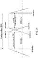
- Figure 2 illustrates an exemplary frequency band 200 with a first sub-band 202 and an adjacent second sub-band 204.
- the frequency band 200 is LTE band 41 which ranges from 2496 MHz to 2690MHz.
- the first sub-band 202 is from 2496MHz to 2570MHz.
- the second sub-band 204 is from 2630 to 2496MHz.
- the first sub-band 202 and the second sub-band are separated by a 60MHz guard band.
- the first sub-band 202 and the second sub-band 204 are respectively the uplink sub-band and the downlink sub-band for a frequency division duplexing band for another air interface, e.g. 3G UMTS.
- the first sub-band 202 is approximately uplink sub-band for 3G UMTS band 7
- the second sub-band 204 is approximately downlink sub-band for 3G UMTS band 7.
- the uplink sub-band for 3G UMTS band 7 is 2500MHz to 2570MHz.
- the downlink sub-band for 3G UMTS band 7 is 2620MHz to 2690MHz.
- the first sub-band 202 and the second sub-band 204 are used respectively by the small cell with selective filtering 104 and the backhaul wireless modem with selective filtering 106, or vice versa.
- the small cell with selective filtering 104 and the backhaul wireless modem with selective filtering 106 operate in TDD each transmitting when the other is receiving.
- selective filtering is used in each of the small cell and the backhaul wireless modem as will now be described.
- the selective filtering in a transceiver operating in a sub-band, provides enhanced filtering and suppression of undesired signals in the adjacent sub-band used by the other transceiver.
- FIG. 3 illustrates an exemplary small cell with selective filtering 300.
- the small cell with selective filtering 300 employs multiple-input multiple-output (MIMO) technology having two transmission channels and two reception channels.
- MIMO multiple-input multiple-output
- the small cell with selective filtering 300 may have more than two transmission channels and may have more than two reception channels.
- One transmission channel and one reception channel are coupled to a common antenna, through a transmit-receive switch, and to the first transceiver 305.
- the first transceiver 305 is also coupled to the transmit receive-switch, and is configured to select whether the antenna is connected to either the receive channel or the transmit channel depending upon whether the first transceiver 305 is transmitting or receiving.
- the first transceiver is also coupled to the backhaul wireless modem with selective filtering 106.
- the transmit-receive switches enable time domain duplexing operation by the small cell with selective filtering 300, and the subsequently described backhaul wireless modem with selective filtering 106.
- the transmit-receive switches must have sufficient insertion loss, isolation, and power compression to attain the design parameters for the transceiver in which the transmit-receive switches are used.
- the illustrated transmit-receive switches are single pole double throw (SPDT) switches.
- SPDT single pole double throw
- NPDT N pole double throw
- each transmit channel is comprised of a transmitter front end with selective filtering, and an upconverter and a baseband processor of the first transceiver 305.
- each receive channel is comprised of a receiver front end with selective filtering, and a downconverter and the baseband processor of the first transceiver 305.
- the exemplary small cell with selective filtering 300 comprises a first transmitter front end 302a and a second transmitter front end 302a, and a first receiver front end 304a and a second receiver front end 304a.
- the first transmitter front end 302a and the first receiver front end 304a are alternately coupled to a first antenna 316a.
- the second transmitter front end 302b and the second receiver front end 304b are alternately coupled to a second antenna 316b.
- the first transmitter front end 302a, the second transmitter front end 302b, the first receiver front end 304a, and the second receiver front end 304b are coupled to a first transceiver 305.
- the first transceiver 305 includes at least one baseband processor, at least one upconverter, and at least one downconverter. In another embodiment, e.g . for a first transceiver 305 implementing two MIMO transmit and two MIMO receive channels, the first transceiver 305 includes at least one baseband processor, two upconverters, and two downconverters. In another embodiment, the first transceiver 305 includes at least one baseband processor, two upconverters, and two downconverters.
- the output of the first transmitter front end 302a and the input of the first receiver front end 304a are respectively coupled to the first terminal and the second terminal of a first transmit-receive (TR) switch 312a.
- the output of the second transmitter front end 302b and the input of the second receiver front end 304b are respectively coupled to the first terminal and the second terminal of a second transmit-receive switch 312b.
- the first transmit-receive switch 312a and the second transmit-receive switch 312b are single pole double throw (SPDT) switches.
- the common terminals of the first transmit-receive switch 312a and second transmit-receive switch 312b are respectively coupled to a first antenna 316a and a second antenna 316b.
- the first transmit-receive switch 312a and the second transmit-receive switch 312b are respectively coupled to the first transceiver 305 by the first TR switch control line 330a and the second TR switch control line 330b.
- Control signals, from the first transceiver 305 are communicated over the first TR switch control line 330a and the second TR switch control line 330b, and respectively control the position of the first transmit-receive switch 312a and the second transmit-receive switch 312b to permit the small cell with selective filtering 300 to switch between transmitting and receiving to properly operate in time division duplexing mode.
- a first transmit signal 320a flows in the first transmitter front end 302a from the first transceiver 305 towards the first antenna 316a.
- a second transmit signal 320b flows respectively in the second transmitter front end 302b from the first transceiver 305 towards the second antenna 316b.
- a first receive signal 322a flows in the first receiver front end 304a to the first transceiver 305 away from the first antenna 316a.
- a second receive signal 322b flows respectively in the second receiver front end 304b to the first transceiver 305 away from the second antenna 316b.
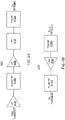
- each transmitter front end includes a power amplifier 408, a low pass filter (LPF) 410, and a first selective filter (SF) 416a.
- An input of the power amplifier 408 is coupled to an output of a transceiver, e.g . an output of an exciter in the transceiver.
- An output of the power amplifier 408 is coupled to an input of the low pass filter 410.
- An output of the low pass filter 410 is coupled to an input of the first selective filter 416a.
- the output of the first selective filter 416a is coupled to a transmission-receive switch.
- a buffer amplifier (BA) 414 is inserted between the transceiver and the power amplifier 408.
- the input of the buffer amplifier 414 is coupled to an output of the transceiver.
- the output of the buffer amplifier 414 is coupled to an input of the power amplifier 408.
- a second selective filter 416b is inserted between the transceiver and the power amplifier 408 to provide additional filtering and suppression of out of sub-band signals broadcast from the transceiver.
- the input of the second selective filter 416b is coupled to the output of either the buffer amplifier 414, if used, or alternatively to the output of the transceiver.
- the output of the second selective filter 416b is coupled to the input of the power amplifier 408.
- the second selective filter 416b can be employed to further suppress out-of-band noise, e.g . sideband noise, generated by the transmitter of a transceiver.
- the second selective filter 416b may be required if the transmitter front end has high gain which would amplify such noise.
- the one or more selective filters in the transmitter front end attenuate signals, broadcast by the transmitter of the transceiver and in the sub-band of the other transceiver, by at least fifty-five decibels.
- FIG 4B illustrates one embodiment of a receiver front end 430.
- each receiver front end includes a third selective filter 416c and a low noise amplifier 436.
- An output of the third selective filter 416c is coupled to an input of a low noise amplifier 436.
- An input of the third selective filter 416c is coupled to a transmit-receive switch.
- An output of the low noise amplifier 436 is coupled to an input of the transceiver, e.g . the input of a downconverter.
- a fourth selective filter 416d is coupled between the input of a transceiver and the output of the low noise amplifier 436 to provide enhanced filtering and suppression of out-of-band signals, e.g. from the adjacent transmitter.
- the selective filter(s) in the receiver front end attenuates signals, broadcast by and in the sub-band of the other transceiver, by at least fifty-five decibels.
- FIG. 5 illustrates an exemplary embodiment of a backhaul wireless modem with selective filtering 500.
- the exemplary backhaul wireless modem with selective filtering 500 employs multiple-input multiple-output (MIMO) technology having two transmission channels and four reception channels.
- MIMO multiple-input multiple-output
- the backhaul wireless modem with selective filtering 500 may have more than two transmission channels, and may have two or more than four reception channels.
- a multielement, e.g. eight elements, smart antenna having beam steering is used in lieu of the individual antennas in the backhaul wireless modem with selective filtering 500.
- Such beam steering increases equivalent isotropic receiver sensitivity and radiated power of the backhaul wireless modem with selective filtering 500
- Two pairs of transmission and reception channels are coupled to common antennas through transmit-receive switches, and to the second transceiver 505 in a manner similar to the illustration of Figure 3 .
- Two additional receiver front ends with selective filtering are used to provide extra link margin, and are also coupled to the second transceiver 505 and individual antennas.
- the implementations of the transmitter front ends and receiver front ends of the backhaul wireless modem with selective filtering 500 may be implemented as described above in Figures 4A and 4B .
- the second transceiver 505 includes at least one baseband processor, at least one upconverter, and at least one downconverter.
- the second transceiver 505 includes at least one baseband processor, two upconverters, and four downconverters.
- the second transceiver 505 is also coupled to the small cell with selective filtering 104.
- a third transmitter front end with selective filtering 502a has an input coupled to an output of the second transceiver 505, and an output coupled to a terminal of a third transmit-receive switch 512a.
- a third receiver front end with selective filtering 504a has an input coupled to another terminal of the third transmit-receive switch 512a, and an output coupled to an input of the second transceiver 505.
- the output of the third transmit-receive switch 512a is coupled to a third antenna 516a.
- a third TR switch control line 530a couples the second transceiver 505 to the third TR switch 512a to ensure proper time division duplexing operation.
- a fourth transmitter front end with selective filtering 502b has an input coupled to an output of the second transceiver 505, and an output coupled to a terminal of a fourth transmit-receive switch 512b.
- a fourth receiver front end with selective filtering 504b has an input coupled to another terminal of the fourth transmit-receive switch 512b, and an output coupled to an input of the second transceiver 505.
- the output of the fourth transmit-receive switch 512b is coupled to a fourth antenna 516b.
- a fourth TR switch control line 530b couples the second transceiver to the third TR switch 512a to ensure proper time division duplexing operation.
- a fifth receiver front end with selective filtering 504c has an input coupled to a fifth antenna 516c, and an output coupled to an input of the second transceiver 505.
- a sixth receiver front end with selective filtering 504d has an input coupled to a sixth antenna 516d, and an output coupled to an input of the second transceiver 505.
- a third transmit signal 520a flows in the third transmitter front end 502a from the second transceiver 505 towards the third antenna 516a.
- a fourth transmit signal 520b flows respectively in the fourth transmitter front end 502b from the second transceiver 505 towards the fourth antenna 516b.
- a third receive signal 522a flows in the third receiver front end 504a to the second transceiver 505 away from the third antenna 516a.
- a fourth receive signal 522b flows respectively in the fourth receiver front end 504b to the second transceiver 505 away from the fourth antenna 516b.
- a fifth receive signal 522c flows in the fifth receiver front end 504c to the second transceiver 505 away from the fifth antenna 516c.
- a sixth receive signal 522d flows in the sixth receiver front end 504d to the second transceiver 505 away from the sixth antenna 516d.
- each selective filter can be implemented with one filter, e.g. a band pass filter having a center frequency and corner frequencies, corresponding to the sub-band being used by the corresponding transceiver system in which the selective filtering is used.
- FIG 6 illustrates another embodiment of a selective filter 600 which utilizes low cost, commercial off the shelf technology.
- the selective filter 600 includes a single pole double throw (SPDT) switch 604 coupled to a three-port filter 602.
- the SPDT switch 604 has two terminals 610a, 610b respectively coupled to two ports 608a, 608b, of the three-port filter 602, corresponding to different sub-bands.
- the SPDT switch 604 also has a common terminal 606b.
- the three-port filter 602 has a common port 606a.
- the common terminal 606b of the SPDT switch 604, and the common port 606a of the three-port filter 602, are the input /output terminals of the selective filter.
- the selective filter 600 is a reciprocal network the common terminal 606b and common port 606a can be used respectively as the input and output of the selective filter 600, or vice versa.
- the isolation between an unconnected terminal (i.e. not selected terminal) and the common terminal of the SPDT switch 604 in the adjacent sub-band is equal to or greater than the corresponding attenuation across the adjacent sub-band of the selective filter. This prevents the undesired out-of-band signals from leaking through the unselected terminal of the SPDT switch 604. Also, the insertion loss and power compression of the SPDT switch 604 should be sufficiently low and high to achieve the design of parameters the transceiver in which the SPDT switch 604 is used.
- the three-port filter 602 is a duplexer, such as a commercial off the shelf duplexer for 3G UMTS band 7. In another embodiment, the three-port filter 602 is a diplexer.
- Figure 7 illustrates one embodiment of a three-port filter 700.
- the three-port filter 700 comprises filter 1 702 and filter 2 704 having a common port 710, and unique ports 706, 708 for each filter.
- both filter 1 702 and filter 2 704 are bandpass filters, e.g. each having a center frequency and corner frequencies corresponding approximately to each sub-band.
- the filter corresponding to the higher frequency sub-band can be implemented with a high pass filter.
- the filter corresponding to the lower frequency sub-band can be implemented with a low pass filter.
- the SPDT switch 604 has a control terminal 612 which can be biased, e.g . by a voltage, to select which terminal 610a, 610b is coupled to the common terminal. This can be used select whether the selective filter 600 uses the filter corresponding to the upper or lower sub-band.
- one selective filter 600 can be manufactured for use in both the small cell with selective filtering 104 and the backhaul wireless modem with selective filtering 106.
- the control terminals 612 of each selective filter 600 is biased to select the one filter in one sub-band for the small cell with selective filtering 104 and the other filter in the second sub-band for the backhaul wireless modem with selective filtering 106.
- the control terminal 612 for the selective filters 600 in the small cell with selective filtering 104 are biased so that they use the filter having a center and corner frequencies about that sub-band.
- Figure 8 illustrates one embodiment of operation of the exemplary communications network with selective filtering 100.
- select filters e.g. by biasing the control terminals 612 of the selective filters 600 used in the small cell with selective filtering 104 and the backhaul wireless modem with selective filtering 106.
- transmit a first signal in the first sub-band from the small cell with selective filtering 104 e.g. to user equipment 102; receive a second signal in the second sub-band at the backhaul wireless modem with selective filtering 106, e.g. from the macro cell 108.
- a signal may be a voltage signal or a current signal.
Landscapes
- Engineering & Computer Science (AREA)
- Signal Processing (AREA)
- Computer Networks & Wireless Communication (AREA)
- Power Engineering (AREA)
- Transceivers (AREA)
Description
- A Long Term Evolution (LTE) wireless network includes an Evolved Universal Terrestrial Radio Access Network (E-UTRAN) (also sometimes referred to simply as the "radio access network" or "RAN") and an Evolved Packet Core (EPC) network (also sometime referred to simply as the "core network").
- The E-UTRAN comprises a set of base stations that wirelessly communicate with user equipment (such as smartphones) using licensed radio frequency spectrum. Each base station is also generally referred to as an "eNodeB" or "eNB."
- One type of eNodeB is a "macro" eNodeB (or eNodeB macro cell), which is a higher-power base station that is typically used to provide base station capacity in a relatively large area that includes both outdoor areas and indoor areas. In general, each location within a service provider's network is notionally within the coverage area of at least one macro eNodeB. However, in practice, there are some locations (for example, within homes and office buildings) for which good coverage cannot be provided by any macro eNodeB in an operator's network. Also, there may be some locations (for example, within public venues such as office buildings, stadiums, airports, etc.) where a large number of users congregate during certain periods. During those periods, the associated macro eNodeBs may not be able provide sufficient base-station capacity to the congregated users, even if it is possible to provide sufficient wireless coverage.
- One type of eNodeB is a "small cell" or "femtocell," which is a lower-power base station. A small cell can be used to provide improved wireless coverage and/or capacity in order to address the issues noted in the previous paragraph. This is done by deploying the small cell directly with the location that has a coverage and/or capacity issue.
- Each eNodeB communicates with entities in the core network (such as, a Serving Gateway (S-GW) and a Mobility Management Entity (MME)) using the "S1 interface" defined by the 3rd Generation Partnership Project (3GPP). Each eNB also communicates with other eNBs using the "X2 interface" defined by the 3GPP. These protocols are Internet Protocol (IP) based and often use public networks such as the Internet. The communication link that couples an eNodeB to the core network is referred as the "back haul" link.
- Such a back haul link can be implemented using a wired connection. The back haul link can also be implemented using a wireless connection. Indeed, in some small cell deployments, the wireless back haul for a small cell eNodeB is provided using a wireless communication link that is implemented with a macro eNodeB. That is, for such a small cell eNodeB, a wireless modem, or backhaul wireless modem, is provided with the small cell that functions as user equipment from the perspective of the macro eNodeB and that functions as the termination point of an IP connection from the perspective of the small cell eNodeB.
- In some cases where this type of wireless backhaul is used with a small cell, the small cell and corresponding backhaul wireless modem are proximate and may operate in the same band using time division duplexing (TDD). However, transmissions by the transmitter of one transceiver in either the small cell or the backhaul wireless backhaul modem may desensitize the receiver of the other transceiver in either the backhaul wireless modem or the small cell, respectively, due to saturation of the receiver caused by the relatively high incident power from the nearby transmitter, and an increased noise floor due to noise, e.g. sideband noise, broadcast by the transmitter.
- A communication system as defined by
independent claim 1, comprising a base station serving a small cell and a backhaul wireless modem. And a method for operating the communication system ofclaim 1, as defined by independent claim 12. Advantageous embodiments are set out in the dependent claims. - Understanding that the drawings depict only exemplary embodiments and are not therefore to be considered limiting in scope, the exemplary embodiments will be described with additional specificity and detail through the use of the accompanying drawings, in which:
-
Figure 1 illustrates a block diagram of an exemplary communications network with selective filtering; -
Figure 2 illustrates an exemplary frequency band with a first sub-band and an adjacent second sub-band; -
Figure 3 illustrates an exemplary small cell with selective filtering; -
Figure 4A illustrates one embodiment of a transmitter front end; -
Figure 4B illustrates one embodiment of a receiver front end; -
Figure 5 illustrates an exemplary embodiment of a backhaul wireless modem with selective filtering; -
Figure 6 illustrates an embodiment of a selective filter; -
Figure 7 illustrates one embodiment of a three-port filter; and -
Figure 8 illustrates one embodiment of operation of the exemplary communications network with selective filtering. - Embodiments described below provide a technique to enable a small cell and a backhaul wireless modem to operate when proximate. Advantageously, embodiments enable the small cell and the backhaul wireless modem to be co-located by using inexpensive components such as commercial off the shelf parts.
-
Figure 1 illustrates a block diagram of an exemplary communications network withselective filtering 100. The communications network withselective filtering 100 includes one or more user equipment (UE) 102, a small cell withselective filtering 104, a backhaul wireless modem withselective filtering 106, and amacro cell 108. In one embodiment, the small cell withselective filtering 104 and the backhaul wireless modem withselective filtering 106 may be packaged together, forming an integrated small cell and backhaul wireless modem withselective filtering 105. - Both the small cell with
selective filtering 104 and themacro cell 108 are base station entities (for example, eNodeBs in the case of a LTE network) and are coupled to the operator'score network 110. Themacro cell 108 can be coupled to thecore network 110 using any suitable wired or wireless backhaul communication link. The small cell withselective filtering 104 is coupled to thecore network 110 using a wireless back haul link implemented with themacro cell 108. The backhaul wireless modem withselective filtering 106 is provided with the small cell withselective filtering 104, and functions as user equipment from the perspective of themacro cell 108 and functions as the termination point of an IP connection from the perspective of the small cell withselective filtering 104. - The small cell with
selective filtering 104 and the backhaul wireless modem withselective filtering 106 may operate, or be used, on the same band (for example LTE band 41) using time division duplexing. When the small cell withselective filtering 104 and backhaul wireless modem withselective filtering 106 are proximate and operate simultaneously using TDD in the same band, the receiver of each may become de-sensitized. To remedy this problem and permit proximate, simultaneous operation, selective filtering is used. Selective filtering involves operating the transceivers of each of the small cell withselective filtering 104 and the backhaul wireless modem withselective filtering 106 on different, but adjacent sub-bands in the same operating band, and providing sufficient filtering in each transceiver to substantially reduce or even eliminate receiver desensitization. Adjacent means, with respect to the proximity of sub-bands, that the sub-bands are separated by a guard band whose bandwidth is equal to, greater than, or less than the guard band specified for frequency division duplexing using the same air interface. - Time division multiplexing is implemented as follows. In one embodiment, the one or more user equipment (UE) 102 and the small cell with
selective filtering 104 transmit and receive wirelessly on a first sub-band of a frequency band when the backhaul wireless modem withselective filtering 106 and amacro cell 108 respectively receive and transmit on the second sub-band of the frequency band.Figure 2 illustrates anexemplary frequency band 200 with afirst sub-band 202 and an adjacent second sub-band 204. In one embodiment, thefrequency band 200 is LTE band 41 which ranges from 2496 MHz to 2690MHz. In another embodiment, thefirst sub-band 202 is from 2496MHz to 2570MHz. In a further embodiment, the second sub-band 204 is from 2630 to 2496MHz. In yet another embodiment, thefirst sub-band 202 and the second sub-band are separated by a 60MHz guard band. In yet a further embodiment, thefirst sub-band 202 and the second sub-band 204 are respectively the uplink sub-band and the downlink sub-band for a frequency division duplexing band for another air interface, e.g. 3G UMTS. In another embodiment, thefirst sub-band 202 is approximately uplink sub-band for 3G UMTS band 7, and the second sub-band 204 is approximately downlink sub-band for 3G UMTS band 7. The uplink sub-band for 3G UMTS band 7 is 2500MHz to 2570MHz. The downlink sub-band for 3G UMTS band 7 is 2620MHz to 2690MHz. - The
first sub-band 202 and the second sub-band 204 are used respectively by the small cell withselective filtering 104 and the backhaul wireless modem withselective filtering 106, or vice versa. The small cell withselective filtering 104 and the backhaul wireless modem withselective filtering 106 operate in TDD each transmitting when the other is receiving. To avoid desensitizing the receiver in each, selective filtering is used in each of the small cell and the backhaul wireless modem as will now be described. The selective filtering in a transceiver, operating in a sub-band, provides enhanced filtering and suppression of undesired signals in the adjacent sub-band used by the other transceiver. -
Figure 3 illustrates an exemplary small cell withselective filtering 300. The small cell withselective filtering 300 employs multiple-input multiple-output (MIMO) technology having two transmission channels and two reception channels. However, in alternative embodiments, the small cell withselective filtering 300 may have more than two transmission channels and may have more than two reception channels. - One transmission channel and one reception channel are coupled to a common antenna, through a transmit-receive switch, and to the
first transceiver 305. Thefirst transceiver 305 is also coupled to the transmit receive-switch, and is configured to select whether the antenna is connected to either the receive channel or the transmit channel depending upon whether thefirst transceiver 305 is transmitting or receiving. The first transceiver is also coupled to the backhaul wireless modem withselective filtering 106. - The transmit-receive switches enable time domain duplexing operation by the small cell with
selective filtering 300, and the subsequently described backhaul wireless modem withselective filtering 106. The transmit-receive switches must have sufficient insertion loss, isolation, and power compression to attain the design parameters for the transceiver in which the transmit-receive switches are used. The illustrated transmit-receive switches are single pole double throw (SPDT) switches. However, N pole double throw (NPDT) switches, where N > 2, can be used to couple two or more pairs of reception and transmission channels to corresponding antennas. - In one embodiment, each transmit channel is comprised of a transmitter front end with selective filtering, and an upconverter and a baseband processor of the
first transceiver 305. In another embodiment, each receive channel is comprised of a receiver front end with selective filtering, and a downconverter and the baseband processor of thefirst transceiver 305. - The exemplary small cell with
selective filtering 300 comprises a first transmitterfront end 302a and a second transmitterfront end 302a, and a first receiverfront end 304a and a second receiverfront end 304a. The first transmitterfront end 302a and the first receiverfront end 304a are alternately coupled to afirst antenna 316a. The second transmitterfront end 302b and the second receiverfront end 304b are alternately coupled to asecond antenna 316b. The first transmitterfront end 302a, the second transmitterfront end 302b, the first receiverfront end 304a, and the second receiverfront end 304b are coupled to afirst transceiver 305. In one embodiment, thefirst transceiver 305 includes at least one baseband processor, at least one upconverter, and at least one downconverter. In another embodiment, e.g. for afirst transceiver 305 implementing two MIMO transmit and two MIMO receive channels, thefirst transceiver 305 includes at least one baseband processor, two upconverters, and two downconverters. In another embodiment, thefirst transceiver 305 includes at least one baseband processor, two upconverters, and two downconverters. - The output of the first transmitter
front end 302a and the input of the first receiverfront end 304a are respectively coupled to the first terminal and the second terminal of a first transmit-receive (TR)switch 312a. The output of the second transmitterfront end 302b and the input of the second receiverfront end 304b are respectively coupled to the first terminal and the second terminal of a second transmit-receiveswitch 312b. In one embodiment, the first transmit-receiveswitch 312a and the second transmit-receiveswitch 312b are single pole double throw (SPDT) switches. The common terminals of the first transmit-receiveswitch 312a and second transmit-receiveswitch 312b are respectively coupled to afirst antenna 316a and asecond antenna 316b. The first transmit-receiveswitch 312a and the second transmit-receiveswitch 312b are respectively coupled to thefirst transceiver 305 by the first TRswitch control line 330a and the second TRswitch control line 330b. Control signals, from thefirst transceiver 305 are communicated over the first TRswitch control line 330a and the second TRswitch control line 330b, and respectively control the position of the first transmit-receiveswitch 312a and the second transmit-receiveswitch 312b to permit the small cell withselective filtering 300 to switch between transmitting and receiving to properly operate in time division duplexing mode. - A first transmit
signal 320a flows in the first transmitterfront end 302a from thefirst transceiver 305 towards thefirst antenna 316a. A second transmitsignal 320b flows respectively in the second transmitterfront end 302b from thefirst transceiver 305 towards thesecond antenna 316b. A first receivesignal 322a flows in the first receiverfront end 304a to thefirst transceiver 305 away from thefirst antenna 316a. A second receivesignal 322b flows respectively in the second receiverfront end 304b to thefirst transceiver 305 away from thesecond antenna 316b. -
Figure 4A illustrates one embodiment of a transmitterfront end 400. In another embodiment, each transmitter front end includes apower amplifier 408, a low pass filter (LPF) 410, and a first selective filter (SF) 416a. An input of thepower amplifier 408 is coupled to an output of a transceiver, e.g. an output of an exciter in the transceiver. An output of thepower amplifier 408 is coupled to an input of thelow pass filter 410. An output of thelow pass filter 410 is coupled to an input of the firstselective filter 416a. The output of the firstselective filter 416a is coupled to a transmission-receive switch. - In one embodiment, a buffer amplifier (BA) 414 is inserted between the transceiver and the
power amplifier 408. The input of thebuffer amplifier 414 is coupled to an output of the transceiver. The output of thebuffer amplifier 414 is coupled to an input of thepower amplifier 408. - In one embodiment, a second
selective filter 416b is inserted between the transceiver and thepower amplifier 408 to provide additional filtering and suppression of out of sub-band signals broadcast from the transceiver. The input of the secondselective filter 416b is coupled to the output of either thebuffer amplifier 414, if used, or alternatively to the output of the transceiver. The output of the secondselective filter 416b is coupled to the input of thepower amplifier 408. The secondselective filter 416b can be employed to further suppress out-of-band noise, e.g. sideband noise, generated by the transmitter of a transceiver. The secondselective filter 416b may be required if the transmitter front end has high gain which would amplify such noise. In one embodiment, the one or more selective filters in the transmitter front end attenuate signals, broadcast by the transmitter of the transceiver and in the sub-band of the other transceiver, by at least fifty-five decibels. -
Figure 4B illustrates one embodiment of a receiverfront end 430. In another embodiment, each receiver front end includes a thirdselective filter 416c and alow noise amplifier 436. An output of the thirdselective filter 416c is coupled to an input of alow noise amplifier 436. An input of the thirdselective filter 416c is coupled to a transmit-receive switch. An output of thelow noise amplifier 436 is coupled to an input of the transceiver, e.g. the input of a downconverter. In the embodiment illustrated inFigure 4B , a fourthselective filter 416d is coupled between the input of a transceiver and the output of thelow noise amplifier 436 to provide enhanced filtering and suppression of out-of-band signals, e.g. from the adjacent transmitter. In one embodiment, the selective filter(s) in the receiver front end attenuates signals, broadcast by and in the sub-band of the other transceiver, by at least fifty-five decibels. -
Figure 5 illustrates an exemplary embodiment of a backhaul wireless modem withselective filtering 500. The exemplary backhaul wireless modem withselective filtering 500 employs multiple-input multiple-output (MIMO) technology having two transmission channels and four reception channels. However, in another embodiment, the backhaul wireless modem withselective filtering 500 may have more than two transmission channels, and may have two or more than four reception channels. In a further embodiment, a multielement, e.g. eight elements, smart antenna having beam steering is used in lieu of the individual antennas in the backhaul wireless modem withselective filtering 500. Such beam steering increases equivalent isotropic receiver sensitivity and radiated power of the backhaul wireless modem withselective filtering 500 - Two pairs of transmission and reception channels are coupled to common antennas through transmit-receive switches, and to the
second transceiver 505 in a manner similar to the illustration ofFigure 3 . Two additional receiver front ends with selective filtering are used to provide extra link margin, and are also coupled to thesecond transceiver 505 and individual antennas. The implementations of the transmitter front ends and receiver front ends of the backhaul wireless modem withselective filtering 500 may be implemented as described above inFigures 4A and 4B . In one embodiment, thesecond transceiver 505 includes at least one baseband processor, at least one upconverter, and at least one downconverter. In another embodiment, thesecond transceiver 505 includes at least one baseband processor, two upconverters, and four downconverters. Thesecond transceiver 505 is also coupled to the small cell withselective filtering 104. - A third transmitter front end with
selective filtering 502a has an input coupled to an output of thesecond transceiver 505, and an output coupled to a terminal of a third transmit-receiveswitch 512a. A third receiver front end with selective filtering 504a has an input coupled to another terminal of the third transmit-receiveswitch 512a, and an output coupled to an input of thesecond transceiver 505. The output of the third transmit-receiveswitch 512a is coupled to athird antenna 516a. A third TRswitch control line 530a couples thesecond transceiver 505 to thethird TR switch 512a to ensure proper time division duplexing operation. - A fourth transmitter front end with
selective filtering 502b has an input coupled to an output of thesecond transceiver 505, and an output coupled to a terminal of a fourth transmit-receiveswitch 512b. A fourth receiver front end with selective filtering 504b has an input coupled to another terminal of the fourth transmit-receiveswitch 512b, and an output coupled to an input of thesecond transceiver 505. The output of the fourth transmit-receiveswitch 512b is coupled to afourth antenna 516b. A fourth TRswitch control line 530b couples the second transceiver to thethird TR switch 512a to ensure proper time division duplexing operation. - A fifth receiver front end with
selective filtering 504c has an input coupled to afifth antenna 516c, and an output coupled to an input of thesecond transceiver 505. A sixth receiver front end with selective filtering 504d has an input coupled to asixth antenna 516d, and an output coupled to an input of thesecond transceiver 505. - A third transmit signal 520a flows in the third transmitter
front end 502a from thesecond transceiver 505 towards thethird antenna 516a. A fourth transmit signal 520b flows respectively in the fourth transmitterfront end 502b from thesecond transceiver 505 towards thefourth antenna 516b. A third receivesignal 522a flows in the third receiver front end 504a to thesecond transceiver 505 away from thethird antenna 516a. A fourth receivesignal 522b flows respectively in the fourth receiver front end 504b to thesecond transceiver 505 away from thefourth antenna 516b. A fifth receivesignal 522c flows in the fifth receiverfront end 504c to thesecond transceiver 505 away from thefifth antenna 516c. A sixth receivesignal 522d flows in the sixth receiver front end 504d to thesecond transceiver 505 away from thesixth antenna 516d. - Returning to
Figure 4 , each selective filter can be implemented with one filter, e.g. a band pass filter having a center frequency and corner frequencies, corresponding to the sub-band being used by the corresponding transceiver system in which the selective filtering is used.Figure 6 , however, illustrates another embodiment of aselective filter 600 which utilizes low cost, commercial off the shelf technology. Theselective filter 600 includes a single pole double throw (SPDT)switch 604 coupled to a three-port filter 602. TheSPDT switch 604 has twoterminals ports port filter 602, corresponding to different sub-bands. TheSPDT switch 604 also has acommon terminal 606b. The three-port filter 602 has acommon port 606a. Thecommon terminal 606b of theSPDT switch 604, and thecommon port 606a of the three-port filter 602, are the input /output terminals of the selective filter. In one embodiment, because theselective filter 600 is a reciprocal network thecommon terminal 606b andcommon port 606a can be used respectively as the input and output of theselective filter 600, or vice versa. - In one embodiment, the isolation between an unconnected terminal (i.e. not selected terminal) and the common terminal of the
SPDT switch 604 in the adjacent sub-band is equal to or greater than the corresponding attenuation across the adjacent sub-band of the selective filter. This prevents the undesired out-of-band signals from leaking through the unselected terminal of theSPDT switch 604. Also, the insertion loss and power compression of theSPDT switch 604 should be sufficiently low and high to achieve the design of parameters the transceiver in which theSPDT switch 604 is used. - In one embodiment, the three-
port filter 602 is a duplexer, such as a commercial off the shelf duplexer for 3G UMTS band 7. In another embodiment, the three-port filter 602 is a diplexer. -
Figure 7 illustrates one embodiment of a three-port filter 700. The three-port filter 700 comprisesfilter 1 702 andfilter 2 704 having acommon port 710, andunique ports filter 1 702 andfilter 2 704 are bandpass filters, e.g. each having a center frequency and corner frequencies corresponding approximately to each sub-band. In another embodiment, the filter corresponding to the higher frequency sub-band can be implemented with a high pass filter. In a further embodiment, the filter corresponding to the lower frequency sub-band can be implemented with a low pass filter. - Returning to
Figure 6 , theSPDT switch 604 has acontrol terminal 612 which can be biased, e.g. by a voltage, to select which terminal 610a, 610b is coupled to the common terminal. This can be used select whether theselective filter 600 uses the filter corresponding to the upper or lower sub-band. Thus, oneselective filter 600 can be manufactured for use in both the small cell withselective filtering 104 and the backhaul wireless modem withselective filtering 106. When implemented in the small cell withselective filtering 104 and the backhaul wireless modem withselective filtering 106, thecontrol terminals 612 of eachselective filter 600 is biased to select the one filter in one sub-band for the small cell withselective filtering 104 and the other filter in the second sub-band for the backhaul wireless modem withselective filtering 106. For example, if the small cell withselective filtering 104 operates in the higher frequency sub-band, then thecontrol terminal 612 for theselective filters 600 in the small cell withselective filtering 104 are biased so that they use the filter having a center and corner frequencies about that sub-band. -
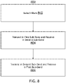
Figure 8 illustrates one embodiment of operation of the exemplary communications network withselective filtering 100. Inblock 802, in one embodiment, select filters, e.g. by biasing thecontrol terminals 612 of theselective filters 600 used in the small cell withselective filtering 104 and the backhaul wireless modem withselective filtering 106. Inblock 804, transmit in a first sub-band of a frequency band in which time division duplexing is required, while receiving in a second sub-band of the frequency band. In one embodiment, transmit a first signal in the first sub-band from the small cell withselective filtering 104, e.g. to user equipment 102; receive a second signal in the second sub-band at the backhaul wireless modem withselective filtering 106, e.g. from themacro cell 108. Inblock 806, transmit in the second sub-band, while receiving in the first sub-band. In one embodiment, receive a third signal in the first sub-band at the small cell withselective filtering 104, e.g. from user equipment 102; transmit a fourth signal in the second sub-band from the backhaul wireless modem withselective filtering 106, e.g. to themacro cell 108. - A number of embodiments of the invention defined by the following claims have been described. Nevertheless, it will be understood that various modifications to the described embodiments may be made without departing from the scope of the claimed invention. Accordingly, other embodiments are within the scope of the following claims. For example, a signal may be a voltage signal or a current signal.
Claims (12)
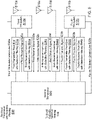
- A communications system operating in a frequency band (200), comprising:a base station serving a small cell with selective filtering (104), wherein the base station serving the small cell with selective filtering comprises a first receiver front end (304a) and a first transmitter front end (302a), wherein the first transmitter front end comprises a first selective filter, wherein the first receiver front end comprises a second selective filter, wherein each of the first selective filter and the second selective filter comprises a first three port filter (602) coupled to a first single pole double throw, SPDT, switch (604), wherein the first three port filter comprises two passbands, where one of the two passbands is in a first sub-band, and wherein the first SPDT switch in each of the first selective filter and the second selective filter is set to select the first sub-band;a backhaul wireless modem with selective filtering (106) coupled to the base station serving the small cell, wherein the backhaul wireless modem with selective filtering comprises a second receiver front end (504a) and a second transmitter front end (502a), wherein the second transmitter front end comprises a third selective filter, wherein the second receiver front end comprises a fourth selective filter, wherein each of the third selective filter and the fourth selective filter comprises a second three port filter (602) coupled to a second SPDT switch (604), wherein the second three port filter comprises the two passbands, and wherein the second SPDT switch in each of the third selective filter and the fourth selective filter is set to select a second sub-band;wherein the base station serving the small cell with selective filtering is configured to only transmit and receive in the first sub-band (202) of the frequency band through a first interface configured to facilitate communications with user equipment (102) when the backhaul wireless modem with selective filtering is respectively receiving and transmitting in the second sub-band (204) of the frequency band through a second interface configured to facilitate communications with macro cell (108);wherein the backhaul wireless modem with selective filtering is configured to only transmit and receive in the second sub-band when the base station serving the small cell is respectively receiving and transmitting in the first sub-band; andwherein the first sub-band and the second sub-band are adjacent.
- The communications system of claim 1, wherein the base station serving the small cell with selective filtering and the backhaul wireless modem with selective filtering are coupled by an Ethernet connection.
- The communications system of claim 1, wherein the base station serving the small cell with selective filtering and the backhaul wireless modem with selective filtering are co-packaged.
- The communications system of claim 1, wherein the base station serving the small cell with selective filtering and the backhaul wireless modem with selective filtering each have at least two reception channels and at least two transmission channels.
- The communications system of claim 1, wherein the base station serving the small cell with selective filtering further comprises:a first transceiver;the first transmitter front end with selective filtering coupled to the first transceiver;the first receiver front end with selective filtering coupled to the first transceiver;a first transmit-receive switch coupled to the first transmitter front end with selective filtering and the first receiver front end with selective filtering;at least one antenna coupled to the first transmit-receive switch; andwherein the first transmit-receive switch is configured to connect an antenna to either the first receiver front end with selective filtering or the first transmitter front end with selective filtering depending upon whether the base station serving the small cell with selective filtering is receiving or transmitting.
- The communications system of claim 5, wherein the first transmitter front end with selective filtering further comprises:a power amplifier(408) coupled to the first transceiver;a low pass filter (410) coupled to the power amplifier; andwherein the first selective filter (416a) is coupled to the low pass filter and the first transmit-receive switch.
- The communications system of claim 6, wherein receiver front end with selective filtering further comprises a low noise amplifier (436) coupled to the second selective filter and the first transceiver.
- The communications system of claim 6, wherein the first selective filter is a duplexer.
- The communications system of claim 6, wherein the first selective filter comprises:a first three-port filter (700) having three ports and two filters;a first single pole double pole (SPDT) switch having two terminals, a common terminal, and a control terminal;wherein two ports of the first three-port filter are coupled to the two terminals of the first SPDT switch; andwherein the first SPDT switch is configured to select one of the two filters of the first three-port filter based upon a signal applied to the control terminal of the first SPDT switch.
- The communications system of claim 6, wherein the second filter is a duplexer.
- The communications system of claim 6, wherein the receiver front end with selective filtering further comprises a low noise amplifier coupled to the second selective filter and the first transceiver.
- A method for the operating the base station serving the small cell and the backhaul wireless modem of claim 1, comprising:transmitting from the base station serving the small cell on the first sub-band;when the base station serving the small cell is transmitting, receiving on the backhaul wireless modem, coupled to the small cell, on the second sub-band in the frequency band;receiving on the base station serving the small cell on the first sub-band; andwhen the base station serving the small cell is receiving, transmitting from the backhaul wireless modem on the second sub-band.
Applications Claiming Priority (2)
| Application Number | Priority Date | Filing Date | Title |
|---|---|---|---|
| US201662435515P | 2016-12-16 | 2016-12-16 | |
| PCT/US2017/063455 WO2018111534A1 (en) | 2016-12-16 | 2017-11-28 | Method and apparatus for operating co-located transceivers on the same frequency band |
Publications (3)
| Publication Number | Publication Date |
|---|---|
| EP3556027A1 EP3556027A1 (en) | 2019-10-23 |
| EP3556027A4 EP3556027A4 (en) | 2020-08-19 |
| EP3556027B1 true EP3556027B1 (en) | 2022-10-05 |
Family
ID=62559167
Family Applications (1)
| Application Number | Title | Priority Date | Filing Date |
|---|---|---|---|
| EP17880141.1A Not-in-force EP3556027B1 (en) | 2016-12-16 | 2017-11-28 | Method and apparatus for operating co-located transceivers on the same frequency band |
Country Status (4)
| Country | Link |
|---|---|
| US (1) | US10567151B2 (en) |
| EP (1) | EP3556027B1 (en) |
| CN (1) | CN110235391B (en) |
| WO (1) | WO2018111534A1 (en) |
Families Citing this family (1)
| Publication number | Priority date | Publication date | Assignee | Title |
|---|---|---|---|---|
| WO2018111534A1 (en) * | 2016-12-16 | 2018-06-21 | Commscope Technologies Llc | Method and apparatus for operating co-located transceivers on the same frequency band |
Family Cites Families (46)
| Publication number | Priority date | Publication date | Assignee | Title |
|---|---|---|---|---|
| EP1006668B1 (en) * | 1998-11-30 | 2011-01-05 | Sony Deutschland GmbH | Dual frequency band transceiver |
| US6865169B1 (en) * | 1999-11-02 | 2005-03-08 | Ipwireless, Inc. | Cellular wireless internet access system using spread spectrum and internet protocol |
| CA2323881A1 (en) * | 2000-10-18 | 2002-04-18 | Dps Wireless Inc. | Adaptive personal repeater |
| US7289494B2 (en) * | 2001-12-06 | 2007-10-30 | Pulse-Link, Inc. | Systems and methods for wireless communication over a wide bandwidth channel using a plurality of sub-channels |
| US8204036B2 (en) * | 2007-02-28 | 2012-06-19 | Motorola Mobility, Inc. | Method and apparatus for coexistence |
| WO2008109569A2 (en) * | 2007-03-02 | 2008-09-12 | Qualcomm Incorporated | Physical layer repeater utilizing real time measurement metrics and adaptive antenna array to promote signal integrity and amplification |
| US8228878B2 (en) * | 2007-05-31 | 2012-07-24 | Telefonaktiebolaget Lm Ericsson (Publ) | Method and system of communications |
| WO2009014764A1 (en) * | 2007-07-25 | 2009-01-29 | Teenay Wireless, Inc. | A multi-tier backhaul network system with traffic differentiation and advanced processing capabilities and methods therefor |
| US8023886B2 (en) * | 2007-09-28 | 2011-09-20 | Broadcom Corporation | Method and system for repeater with gain control and isolation via polarization |
| US7729724B2 (en) * | 2007-11-19 | 2010-06-01 | Broadcom Corporation | RF front-end and applications thereof |
| KR101485977B1 (en) * | 2007-11-21 | 2015-01-23 | 삼성전자주식회사 | Frame structure, method and apparatus for resource allocation in a mobile communication system based on a full-duplex relay scheme |
| US8457549B2 (en) * | 2008-02-29 | 2013-06-04 | Lingna Holdings Pte., Llc | Multi-user MIMO relay protocol with self-interference cancellation |
| KR101457704B1 (en) * | 2008-06-19 | 2014-11-04 | 엘지전자 주식회사 | Radio transceiver and relay station with it |
| US8761824B2 (en) * | 2008-06-27 | 2014-06-24 | Qualcomm Incorporated | Multi-carrier operation in a wireless communication network |
| US8594008B2 (en) * | 2008-11-18 | 2013-11-26 | Qualcomm Incorporated | Relay communications methods and apparatus |
| US20110292863A1 (en) * | 2008-11-26 | 2011-12-01 | Oliver Braz | Single input single output repeater for relaying a multiple input multiple output signal |
| US20100234071A1 (en) * | 2009-03-12 | 2010-09-16 | Comsys Communication & Signal Processing Ltd. | Vehicle integrated communications system |
| US8849186B2 (en) * | 2009-05-12 | 2014-09-30 | Qualcomm Incorporated | Repeater communication using inserted low power sequences |
| US8305941B2 (en) * | 2009-09-02 | 2012-11-06 | Cohen Allen S | Broadband combining system with high spectrum efficiency for use in wireless communications |
| US8718542B2 (en) * | 2009-09-23 | 2014-05-06 | Powerwave Technologies S.A.R.L. | Co-location of a pico eNB and macro up-link repeater |
| US9281889B2 (en) * | 2010-02-16 | 2016-03-08 | Lg Electronics Inc. | Relay node apparatus for transmitting and receiving signal according to link operation mode in wireless communication system and method thereof |
| IT1398534B1 (en) * | 2010-02-25 | 2013-03-01 | Wisytech S R L | EQUIPMENT FOR FEMTOCELLE TELECOMMUNICATION SYSTEM. |
| CN102859902B (en) * | 2010-04-22 | 2016-03-30 | 瑞典爱立信有限公司 | multi-antenna device |
| EP2567563B1 (en) * | 2010-05-03 | 2014-10-15 | Telefonaktiebolaget LM Ericsson (publ) | Propagating system information changes to relays |
| CN102377470B (en) * | 2010-08-13 | 2015-08-12 | 中兴通讯股份有限公司 | Reconfigurable radio node and the method with the collaborative work of macrocell WAP (wireless access point) |
| US9185711B2 (en) * | 2010-09-14 | 2015-11-10 | Qualcomm Incorporated | Method and apparatus for mitigating relay interference |
| EP2633636B1 (en) * | 2010-10-29 | 2017-11-08 | Telefonaktiebolaget LM Ericsson (publ) | Self-interference suppression control for a relay node |
| CN103190090B (en) * | 2010-11-03 | 2016-05-18 | 瑞典爱立信有限公司 | Self-interference in full duplex MIMO repeater suppresses |
| US9154987B2 (en) * | 2010-12-30 | 2015-10-06 | Nokia Solutions And Networks Oy | Relay-to-relay interference coordination in a wireless communication network |
| US20120224472A1 (en) * | 2011-03-04 | 2012-09-06 | Electronics And Telecommunications Research Institute | Method for relaying of base station, method for relaying of terminal and method for transmitting |
| EP2742748A4 (en) * | 2011-08-12 | 2015-08-26 | Intel Corp | System and method of uplink power control in a wireless communication system |
| US9185684B2 (en) * | 2011-09-14 | 2015-11-10 | Marvell World Trade Ltd | Using non-uniform frequency bands for coexistence among multiple wireless communication technologies |
| US8934398B2 (en) * | 2011-10-07 | 2015-01-13 | Qualcomm Incorporated | System, apparatus, and method for repeater pilot signal generation in wireless communication systems |
| US20130143483A1 (en) * | 2011-12-06 | 2013-06-06 | Qualcomm Incorporated | Maintaining repeater stability in a multi-repeater scenario |
| KR20130090669A (en) * | 2012-02-06 | 2013-08-14 | 삼성전자주식회사 | Method and apparatus for centralized scheduling with inter-cell interference coordination in heterogeneous networks |
| US9001712B2 (en) * | 2012-05-02 | 2015-04-07 | Texas Instruments Incorporated | Transmit signal cancelation apparatus and methods |
| US8995312B2 (en) * | 2012-12-21 | 2015-03-31 | Hcl Technologies Limited | Multi-channel broadband re-configurable RF front end for software defined radio / cognitive radio |
| RU2654204C2 (en) * | 2013-09-25 | 2018-05-17 | Сони Корпорейшн | Communication management device, the method for controlling communication, the radio communication device and the method of radio communication |
| CN106031219B (en) * | 2014-02-17 | 2020-01-14 | 瑞典爱立信有限公司 | Processing of wireless backhaul links |
| CN104883202B (en) * | 2014-02-27 | 2018-05-29 | 华为技术有限公司 | A kind of method and trunking for reducing adjacent frequency interference |
| US20170055304A1 (en) * | 2014-04-28 | 2017-02-23 | Telefonaktiebolaget Lm Ericsson (Publ) | Connection establishment in a wireless backhaul network |
| US10038471B2 (en) * | 2015-01-27 | 2018-07-31 | Electronics And Telecommunications Research Institute | Method and apparatus for canceling self-interference |
| US10111206B2 (en) * | 2016-05-09 | 2018-10-23 | Cisco Technology, Inc. | Directing client devices between co-located macro and micro wireless cells |
| US10498521B2 (en) * | 2016-08-31 | 2019-12-03 | Skyworks Solutions, Inc. | Switched-filter duplexing architecture for front-end systems |
| WO2018111534A1 (en) * | 2016-12-16 | 2018-06-21 | Commscope Technologies Llc | Method and apparatus for operating co-located transceivers on the same frequency band |
| EP4236107A3 (en) * | 2017-04-07 | 2023-10-18 | CommScope Technologies LLC | Output muting for active repeater systems |
-
2017
- 2017-11-28 WO PCT/US2017/063455 patent/WO2018111534A1/en not_active Ceased
- 2017-11-28 CN CN201780084593.6A patent/CN110235391B/en not_active Expired - Fee Related
- 2017-11-28 EP EP17880141.1A patent/EP3556027B1/en not_active Not-in-force
- 2017-12-15 US US15/844,410 patent/US10567151B2/en active Active
Also Published As
| Publication number | Publication date |
|---|---|
| WO2018111534A1 (en) | 2018-06-21 |
| CN110235391B (en) | 2020-12-08 |
| EP3556027A1 (en) | 2019-10-23 |
| CN110235391A (en) | 2019-09-13 |
| US20180175998A1 (en) | 2018-06-21 |
| EP3556027A4 (en) | 2020-08-19 |
| US10567151B2 (en) | 2020-02-18 |
Similar Documents
| Publication | Publication Date | Title |
|---|---|---|
| US12081498B2 (en) | Channelization for signal boosters | |
| US12407402B2 (en) | Time division duplex (TDD) network protection repeater | |
| US12082094B2 (en) | Communication by a repeater system including a network of radio frequency repeater devices | |
| KR101852894B1 (en) | Antenna switching system and method | |
| US9154171B2 (en) | Reconfigurable radio frequency circuits and methods of receiving | |
| US9191098B2 (en) | Capability reporting for relay nodes in wireless networks | |
| EP2664184B1 (en) | Bandwidth configuration and reporting for relay links | |
| US9236930B2 (en) | Methods and apparatus for antenna tuning | |
| CN108292948A (en) | The channelizing of Signal Booster | |
| US20240163773A1 (en) | Method for access control, relay terminal and network device | |
| CN116390242B (en) | Control information of intelligent repeaters in wireless communication systems | |
| CN118489290A (en) | Network integration method and device for nodes | |
| WO2012096605A1 (en) | Capability reporting for relay nodes in wireless networks | |
| EP3556027B1 (en) | Method and apparatus for operating co-located transceivers on the same frequency band | |
| EP3944514B1 (en) | Time division duplex (tdd) network protection repeater | |
| US20240235658A9 (en) | Operating and/or configuring a repeater device for enabling the repeater device to be operated together with a user equipment |
Legal Events
| Date | Code | Title | Description |
|---|---|---|---|
| STAA | Information on the status of an ep patent application or granted ep patent |
Free format text: STATUS: THE INTERNATIONAL PUBLICATION HAS BEEN MADE |
|
| PUAI | Public reference made under article 153(3) epc to a published international application that has entered the european phase |
Free format text: ORIGINAL CODE: 0009012 |
|
| STAA | Information on the status of an ep patent application or granted ep patent |
Free format text: STATUS: REQUEST FOR EXAMINATION WAS MADE |
|
| 17P | Request for examination filed |
Effective date: 20190624 |
|
| AK | Designated contracting states |
Kind code of ref document: A1 Designated state(s): AL AT BE BG CH CY CZ DE DK EE ES FI FR GB GR HR HU IE IS IT LI LT LU LV MC MK MT NL NO PL PT RO RS SE SI SK SM TR |
|
| AX | Request for extension of the european patent |
Extension state: BA ME |
|
| DAV | Request for validation of the european patent (deleted) | ||
| DAX | Request for extension of the european patent (deleted) | ||
| A4 | Supplementary search report drawn up and despatched |
Effective date: 20200716 |
|
| RIC1 | Information provided on ipc code assigned before grant |
Ipc: H04B 1/401 20150101ALI20200710BHEP Ipc: H04B 7/26 20060101ALI20200710BHEP Ipc: H04B 7/155 20060101AFI20200710BHEP |
|
| GRAP | Despatch of communication of intention to grant a patent |
Free format text: ORIGINAL CODE: EPIDOSNIGR1 |
|
| STAA | Information on the status of an ep patent application or granted ep patent |
Free format text: STATUS: GRANT OF PATENT IS INTENDED |
|
| INTG | Intention to grant announced |
Effective date: 20220107 |
|
| GRAJ | Information related to disapproval of communication of intention to grant by the applicant or resumption of examination proceedings by the epo deleted |
Free format text: ORIGINAL CODE: EPIDOSDIGR1 |
|
| STAA | Information on the status of an ep patent application or granted ep patent |
Free format text: STATUS: REQUEST FOR EXAMINATION WAS MADE |
|
| INTC | Intention to grant announced (deleted) | ||
| GRAP | Despatch of communication of intention to grant a patent |
Free format text: ORIGINAL CODE: EPIDOSNIGR1 |
|
| STAA | Information on the status of an ep patent application or granted ep patent |
Free format text: STATUS: GRANT OF PATENT IS INTENDED |
|
| INTG | Intention to grant announced |
Effective date: 20220422 |
|
| GRAS | Grant fee paid |
Free format text: ORIGINAL CODE: EPIDOSNIGR3 |
|
| GRAA | (expected) grant |
Free format text: ORIGINAL CODE: 0009210 |
|
| STAA | Information on the status of an ep patent application or granted ep patent |
Free format text: STATUS: THE PATENT HAS BEEN GRANTED |
|
| AK | Designated contracting states |
Kind code of ref document: B1 Designated state(s): AL AT BE BG CH CY CZ DE DK EE ES FI FR GB GR HR HU IE IS IT LI LT LU LV MC MK MT NL NO PL PT RO RS SE SI SK SM TR |
|
| REG | Reference to a national code |
Ref country code: GB Ref legal event code: FG4D |
|
| REG | Reference to a national code |
Ref country code: CH Ref legal event code: EP |
|
| REG | Reference to a national code |
Ref country code: AT Ref legal event code: REF Ref document number: 1523411 Country of ref document: AT Kind code of ref document: T Effective date: 20221015 |
|
| REG | Reference to a national code |
Ref country code: IE Ref legal event code: FG4D |
|
| REG | Reference to a national code |
Ref country code: DE Ref legal event code: R096 Ref document number: 602017062481 Country of ref document: DE |
|
| REG | Reference to a national code |
Ref country code: LT Ref legal event code: MG9D |
|
| PGFP | Annual fee paid to national office [announced via postgrant information from national office to epo] |
Ref country code: GB Payment date: 20221128 Year of fee payment: 6 Ref country code: DE Payment date: 20221125 Year of fee payment: 6 |
|
| REG | Reference to a national code |
Ref country code: NL Ref legal event code: MP Effective date: 20221005 |
|
| REG | Reference to a national code |
Ref country code: AT Ref legal event code: MK05 Ref document number: 1523411 Country of ref document: AT Kind code of ref document: T Effective date: 20221005 |
|
| PG25 | Lapsed in a contracting state [announced via postgrant information from national office to epo] |
Ref country code: NL Free format text: LAPSE BECAUSE OF FAILURE TO SUBMIT A TRANSLATION OF THE DESCRIPTION OR TO PAY THE FEE WITHIN THE PRESCRIBED TIME-LIMIT Effective date: 20221005 |
|
| PG25 | Lapsed in a contracting state [announced via postgrant information from national office to epo] |
Ref country code: SE Free format text: LAPSE BECAUSE OF FAILURE TO SUBMIT A TRANSLATION OF THE DESCRIPTION OR TO PAY THE FEE WITHIN THE PRESCRIBED TIME-LIMIT Effective date: 20221005 Ref country code: PT Free format text: LAPSE BECAUSE OF FAILURE TO SUBMIT A TRANSLATION OF THE DESCRIPTION OR TO PAY THE FEE WITHIN THE PRESCRIBED TIME-LIMIT Effective date: 20230206 Ref country code: NO Free format text: LAPSE BECAUSE OF FAILURE TO SUBMIT A TRANSLATION OF THE DESCRIPTION OR TO PAY THE FEE WITHIN THE PRESCRIBED TIME-LIMIT Effective date: 20230105 Ref country code: LT Free format text: LAPSE BECAUSE OF FAILURE TO SUBMIT A TRANSLATION OF THE DESCRIPTION OR TO PAY THE FEE WITHIN THE PRESCRIBED TIME-LIMIT Effective date: 20221005 Ref country code: FI Free format text: LAPSE BECAUSE OF FAILURE TO SUBMIT A TRANSLATION OF THE DESCRIPTION OR TO PAY THE FEE WITHIN THE PRESCRIBED TIME-LIMIT Effective date: 20221005 Ref country code: ES Free format text: LAPSE BECAUSE OF FAILURE TO SUBMIT A TRANSLATION OF THE DESCRIPTION OR TO PAY THE FEE WITHIN THE PRESCRIBED TIME-LIMIT Effective date: 20221005 Ref country code: AT Free format text: LAPSE BECAUSE OF FAILURE TO SUBMIT A TRANSLATION OF THE DESCRIPTION OR TO PAY THE FEE WITHIN THE PRESCRIBED TIME-LIMIT Effective date: 20221005 |
|
| PG25 | Lapsed in a contracting state [announced via postgrant information from national office to epo] |
Ref country code: RS Free format text: LAPSE BECAUSE OF FAILURE TO SUBMIT A TRANSLATION OF THE DESCRIPTION OR TO PAY THE FEE WITHIN THE PRESCRIBED TIME-LIMIT Effective date: 20221005 Ref country code: PL Free format text: LAPSE BECAUSE OF FAILURE TO SUBMIT A TRANSLATION OF THE DESCRIPTION OR TO PAY THE FEE WITHIN THE PRESCRIBED TIME-LIMIT Effective date: 20221005 Ref country code: LV Free format text: LAPSE BECAUSE OF FAILURE TO SUBMIT A TRANSLATION OF THE DESCRIPTION OR TO PAY THE FEE WITHIN THE PRESCRIBED TIME-LIMIT Effective date: 20221005 Ref country code: IS Free format text: LAPSE BECAUSE OF FAILURE TO SUBMIT A TRANSLATION OF THE DESCRIPTION OR TO PAY THE FEE WITHIN THE PRESCRIBED TIME-LIMIT Effective date: 20230205 Ref country code: HR Free format text: LAPSE BECAUSE OF FAILURE TO SUBMIT A TRANSLATION OF THE DESCRIPTION OR TO PAY THE FEE WITHIN THE PRESCRIBED TIME-LIMIT Effective date: 20221005 Ref country code: GR Free format text: LAPSE BECAUSE OF FAILURE TO SUBMIT A TRANSLATION OF THE DESCRIPTION OR TO PAY THE FEE WITHIN THE PRESCRIBED TIME-LIMIT Effective date: 20230106 |
|
| REG | Reference to a national code |
Ref country code: CH Ref legal event code: PL |
|
| REG | Reference to a national code |
Ref country code: DE Ref legal event code: R097 Ref document number: 602017062481 Country of ref document: DE |
|
| REG | Reference to a national code |
Ref country code: BE Ref legal event code: MM Effective date: 20221130 |
|
| PG25 | Lapsed in a contracting state [announced via postgrant information from national office to epo] |
Ref country code: SM Free format text: LAPSE BECAUSE OF FAILURE TO SUBMIT A TRANSLATION OF THE DESCRIPTION OR TO PAY THE FEE WITHIN THE PRESCRIBED TIME-LIMIT Effective date: 20221005 Ref country code: RO Free format text: LAPSE BECAUSE OF FAILURE TO SUBMIT A TRANSLATION OF THE DESCRIPTION OR TO PAY THE FEE WITHIN THE PRESCRIBED TIME-LIMIT Effective date: 20221005 Ref country code: MC Free format text: LAPSE BECAUSE OF FAILURE TO SUBMIT A TRANSLATION OF THE DESCRIPTION OR TO PAY THE FEE WITHIN THE PRESCRIBED TIME-LIMIT Effective date: 20221005 Ref country code: LI Free format text: LAPSE BECAUSE OF NON-PAYMENT OF DUE FEES Effective date: 20221130 Ref country code: EE Free format text: LAPSE BECAUSE OF FAILURE TO SUBMIT A TRANSLATION OF THE DESCRIPTION OR TO PAY THE FEE WITHIN THE PRESCRIBED TIME-LIMIT Effective date: 20221005 Ref country code: DK Free format text: LAPSE BECAUSE OF FAILURE TO SUBMIT A TRANSLATION OF THE DESCRIPTION OR TO PAY THE FEE WITHIN THE PRESCRIBED TIME-LIMIT Effective date: 20221005 Ref country code: CZ Free format text: LAPSE BECAUSE OF FAILURE TO SUBMIT A TRANSLATION OF THE DESCRIPTION OR TO PAY THE FEE WITHIN THE PRESCRIBED TIME-LIMIT Effective date: 20221005 Ref country code: CH Free format text: LAPSE BECAUSE OF NON-PAYMENT OF DUE FEES Effective date: 20221130 |
|
| PLBE | No opposition filed within time limit |
Free format text: ORIGINAL CODE: 0009261 |
|
| STAA | Information on the status of an ep patent application or granted ep patent |
Free format text: STATUS: NO OPPOSITION FILED WITHIN TIME LIMIT |
|
| PG25 | Lapsed in a contracting state [announced via postgrant information from national office to epo] |
Ref country code: SK Free format text: LAPSE BECAUSE OF FAILURE TO SUBMIT A TRANSLATION OF THE DESCRIPTION OR TO PAY THE FEE WITHIN THE PRESCRIBED TIME-LIMIT Effective date: 20221005 Ref country code: LU Free format text: LAPSE BECAUSE OF NON-PAYMENT OF DUE FEES Effective date: 20221128 Ref country code: AL Free format text: LAPSE BECAUSE OF FAILURE TO SUBMIT A TRANSLATION OF THE DESCRIPTION OR TO PAY THE FEE WITHIN THE PRESCRIBED TIME-LIMIT Effective date: 20221005 |
|
| 26N | No opposition filed |
Effective date: 20230706 |
|
| PG25 | Lapsed in a contracting state [announced via postgrant information from national office to epo] |
Ref country code: IE Free format text: LAPSE BECAUSE OF NON-PAYMENT OF DUE FEES Effective date: 20221128 |
|
| PG25 | Lapsed in a contracting state [announced via postgrant information from national office to epo] |
Ref country code: SI Free format text: LAPSE BECAUSE OF FAILURE TO SUBMIT A TRANSLATION OF THE DESCRIPTION OR TO PAY THE FEE WITHIN THE PRESCRIBED TIME-LIMIT Effective date: 20221005 Ref country code: FR Free format text: LAPSE BECAUSE OF NON-PAYMENT OF DUE FEES Effective date: 20221205 Ref country code: BE Free format text: LAPSE BECAUSE OF NON-PAYMENT OF DUE FEES Effective date: 20221130 |
|
| PG25 | Lapsed in a contracting state [announced via postgrant information from national office to epo] |
Ref country code: HU Free format text: LAPSE BECAUSE OF FAILURE TO SUBMIT A TRANSLATION OF THE DESCRIPTION OR TO PAY THE FEE WITHIN THE PRESCRIBED TIME-LIMIT; INVALID AB INITIO Effective date: 20171128 |
|
| PG25 | Lapsed in a contracting state [announced via postgrant information from national office to epo] |
Ref country code: CY Free format text: LAPSE BECAUSE OF FAILURE TO SUBMIT A TRANSLATION OF THE DESCRIPTION OR TO PAY THE FEE WITHIN THE PRESCRIBED TIME-LIMIT Effective date: 20221005 |
|
| PG25 | Lapsed in a contracting state [announced via postgrant information from national office to epo] |
Ref country code: MK Free format text: LAPSE BECAUSE OF FAILURE TO SUBMIT A TRANSLATION OF THE DESCRIPTION OR TO PAY THE FEE WITHIN THE PRESCRIBED TIME-LIMIT Effective date: 20221005 Ref country code: IT Free format text: LAPSE BECAUSE OF FAILURE TO SUBMIT A TRANSLATION OF THE DESCRIPTION OR TO PAY THE FEE WITHIN THE PRESCRIBED TIME-LIMIT Effective date: 20221005 |
|
| REG | Reference to a national code |
Ref country code: DE Ref legal event code: R119 Ref document number: 602017062481 Country of ref document: DE |
|
| GBPC | Gb: european patent ceased through non-payment of renewal fee |
Effective date: 20231128 |
|
| PG25 | Lapsed in a contracting state [announced via postgrant information from national office to epo] |
Ref country code: BG Free format text: LAPSE BECAUSE OF FAILURE TO SUBMIT A TRANSLATION OF THE DESCRIPTION OR TO PAY THE FEE WITHIN THE PRESCRIBED TIME-LIMIT Effective date: 20221005 |
|
| PG25 | Lapsed in a contracting state [announced via postgrant information from national office to epo] |
Ref country code: MT Free format text: LAPSE BECAUSE OF FAILURE TO SUBMIT A TRANSLATION OF THE DESCRIPTION OR TO PAY THE FEE WITHIN THE PRESCRIBED TIME-LIMIT Effective date: 20221005 |
|
| PG25 | Lapsed in a contracting state [announced via postgrant information from national office to epo] |
Ref country code: DE Free format text: LAPSE BECAUSE OF NON-PAYMENT OF DUE FEES Effective date: 20240601 |
|
| PG25 | Lapsed in a contracting state [announced via postgrant information from national office to epo] |
Ref country code: GB Free format text: LAPSE BECAUSE OF NON-PAYMENT OF DUE FEES Effective date: 20231128 |
|
| PG25 | Lapsed in a contracting state [announced via postgrant information from national office to epo] |
Ref country code: GB Free format text: LAPSE BECAUSE OF NON-PAYMENT OF DUE FEES Effective date: 20231128 Ref country code: DE Free format text: LAPSE BECAUSE OF NON-PAYMENT OF DUE FEES Effective date: 20240601 |
|
| PG25 | Lapsed in a contracting state [announced via postgrant information from national office to epo] |
Ref country code: TR Free format text: LAPSE BECAUSE OF FAILURE TO SUBMIT A TRANSLATION OF THE DESCRIPTION OR TO PAY THE FEE WITHIN THE PRESCRIBED TIME-LIMIT Effective date: 20221005 |