EP3556027B1 - Verfahren und vorrichtung zum betreiben von benachbarten sendeempfängern auf demselben frequenzband - Google Patents
Verfahren und vorrichtung zum betreiben von benachbarten sendeempfängern auf demselben frequenzband Download PDFInfo
- Publication number
- EP3556027B1 EP3556027B1 EP17880141.1A EP17880141A EP3556027B1 EP 3556027 B1 EP3556027 B1 EP 3556027B1 EP 17880141 A EP17880141 A EP 17880141A EP 3556027 B1 EP3556027 B1 EP 3556027B1
- Authority
- EP
- European Patent Office
- Prior art keywords
- selective
- filter
- band
- small cell
- selective filtering
- Prior art date
- Legal status (The legal status is an assumption and is not a legal conclusion. Google has not performed a legal analysis and makes no representation as to the accuracy of the status listed.)
- Not-in-force
Links
Images


Classifications
-
- H—ELECTRICITY
- H04—ELECTRIC COMMUNICATION TECHNIQUE
- H04L—TRANSMISSION OF DIGITAL INFORMATION, e.g. TELEGRAPHIC COMMUNICATION
- H04L5/00—Arrangements affording multiple use of the transmission path
- H04L5/14—Two-way operation using the same type of signal, i.e. duplex
- H04L5/1461—Suppression of signals in the return path, i.e. bidirectional control circuits
-
- H—ELECTRICITY
- H04—ELECTRIC COMMUNICATION TECHNIQUE
- H04B—TRANSMISSION
- H04B7/00—Radio transmission systems, i.e. using radiation field
- H04B7/14—Relay systems
- H04B7/15—Active relay systems
- H04B7/155—Ground-based stations
- H04B7/15507—Relay station based processing for cell extension or control of coverage area
-
- H—ELECTRICITY
- H04—ELECTRIC COMMUNICATION TECHNIQUE
- H04B—TRANSMISSION
- H04B1/00—Details of transmission systems, not covered by a single one of groups H04B3/00 - H04B13/00; Details of transmission systems not characterised by the medium used for transmission
- H04B1/38—Transceivers, i.e. devices in which transmitter and receiver form a structural unit and in which at least one part is used for functions of transmitting and receiving
-
- H—ELECTRICITY
- H04—ELECTRIC COMMUNICATION TECHNIQUE
- H04L—TRANSMISSION OF DIGITAL INFORMATION, e.g. TELEGRAPHIC COMMUNICATION
- H04L25/00—Baseband systems
- H04L25/02—Details ; arrangements for supplying electrical power along data transmission lines
- H04L25/03—Shaping networks in transmitter or receiver, e.g. adaptive shaping networks
- H04L25/03006—Arrangements for removing intersymbol interference
- H04L25/03159—Arrangements for removing intersymbol interference operating in the frequency domain
-
- H—ELECTRICITY
- H04—ELECTRIC COMMUNICATION TECHNIQUE
- H04W—WIRELESS COMMUNICATION NETWORKS
- H04W84/00—Network topologies
- H04W84/02—Hierarchically pre-organised networks, e.g. paging networks, cellular networks, WLAN [Wireless Local Area Network] or WLL [Wireless Local Loop]
- H04W84/04—Large scale networks; Deep hierarchical networks
- H04W84/042—Public Land Mobile systems, e.g. cellular systems
- H04W84/045—Public Land Mobile systems, e.g. cellular systems using private Base Stations, e.g. femto Base Stations, home Node B
Definitions
- a Long Term Evolution (LTE) wireless network includes an Evolved Universal Terrestrial Radio Access Network (E-UTRAN) (also sometimes referred to simply as the “radio access network” or “RAN”) and an Evolved Packet Core (EPC) network (also sometime referred to simply as the "core network”).
- E-UTRAN Evolved Universal Terrestrial Radio Access Network
- EPC Evolved Packet Core
- the E-UTRAN comprises a set of base stations that wirelessly communicate with user equipment (such as smartphones) using licensed radio frequency spectrum.
- Each base station is also generally referred to as an "eNodeB” or "eNB.”
- eNodeB is a "macro" eNodeB (or eNodeB macro cell), which is a higher-power base station that is typically used to provide base station capacity in a relatively large area that includes both outdoor areas and indoor areas.
- each location within a service provider's network is notionally within the coverage area of at least one macro eNodeB.
- locations for example, within homes and office buildings
- good coverage cannot be provided by any macro eNodeB in an operator's network.
- there may be some locations for example, within public venues such as office buildings, stadiums, airports, etc.
- the associated macro eNodeBs may not be able provide sufficient base-station capacity to the congregated users, even if it is possible to provide sufficient wireless coverage.
- eNodeB is a "small cell” or “femtocell,” which is a lower-power base station.
- a small cell can be used to provide improved wireless coverage and/or capacity in order to address the issues noted in the previous paragraph. This is done by deploying the small cell directly with the location that has a coverage and/or capacity issue.
- Each eNodeB communicates with entities in the core network (such as, a Serving Gateway (S-GW) and a Mobility Management Entity (MME)) using the "S1 interface" defined by the 3rd Generation Partnership Project (3GPP).
- S-GW Serving Gateway
- MME Mobility Management Entity
- 3GPP 3rd Generation Partnership Project
- Each eNB also communicates with other eNBs using the "X2 interface” defined by the 3GPP.
- These protocols are Internet Protocol (IP) based and often use public networks such as the Internet.
- IP Internet Protocol
- the communication link that couples an eNodeB to the core network is referred as the "back haul" link.
- Such a back haul link can be implemented using a wired connection.
- the back haul link can also be implemented using a wireless connection.
- the wireless back haul for a small cell eNodeB is provided using a wireless communication link that is implemented with a macro eNodeB. That is, for such a small cell eNodeB, a wireless modem, or backhaul wireless modem, is provided with the small cell that functions as user equipment from the perspective of the macro eNodeB and that functions as the termination point of an IP connection from the perspective of the small cell eNodeB.
- the small cell and corresponding backhaul wireless modem are proximate and may operate in the same band using time division duplexing (TDD).
- TDD time division duplexing
- transmissions by the transmitter of one transceiver in either the small cell or the backhaul wireless backhaul modem may desensitize the receiver of the other transceiver in either the backhaul wireless modem or the small cell, respectively, due to saturation of the receiver caused by the relatively high incident power from the nearby transmitter, and an increased noise floor due to noise, e.g . sideband noise, broadcast by the transmitter.
- a communication system as defined by independent claim 1 comprising a base station serving a small cell and a backhaul wireless modem. And a method for operating the communication system of claim 1, as defined by independent claim 12.
- Advantageous embodiments are set out in the dependent claims.
- Embodiments described below provide a technique to enable a small cell and a backhaul wireless modem to operate when proximate.
- embodiments enable the small cell and the backhaul wireless modem to be co-located by using inexpensive components such as commercial off the shelf parts.
- FIG. 1 illustrates a block diagram of an exemplary communications network with selective filtering 100.
- the communications network with selective filtering 100 includes one or more user equipment (UE) 102, a small cell with selective filtering 104, a backhaul wireless modem with selective filtering 106, and a macro cell 108.
- UE user equipment
- the small cell with selective filtering 104 and the backhaul wireless modem with selective filtering 106 may be packaged together, forming an integrated small cell and backhaul wireless modem with selective filtering 105.
- Both the small cell with selective filtering 104 and the macro cell 108 are base station entities (for example, eNodeBs in the case of a LTE network) and are coupled to the operator's core network 110.
- the macro cell 108 can be coupled to the core network 110 using any suitable wired or wireless backhaul communication link.
- the small cell with selective filtering 104 is coupled to the core network 110 using a wireless back haul link implemented with the macro cell 108.
- the backhaul wireless modem with selective filtering 106 is provided with the small cell with selective filtering 104, and functions as user equipment from the perspective of the macro cell 108 and functions as the termination point of an IP connection from the perspective of the small cell with selective filtering 104.
- the small cell with selective filtering 104 and the backhaul wireless modem with selective filtering 106 may operate, or be used, on the same band (for example LTE band 41) using time division duplexing.
- the small cell with selective filtering 104 and backhaul wireless modem with selective filtering 106 are proximate and operate simultaneously using TDD in the same band, the receiver of each may become de-sensitized. To remedy this problem and permit proximate, simultaneous operation, selective filtering is used.
- Selective filtering involves operating the transceivers of each of the small cell with selective filtering 104 and the backhaul wireless modem with selective filtering 106 on different, but adjacent sub-bands in the same operating band, and providing sufficient filtering in each transceiver to substantially reduce or even eliminate receiver desensitization.
- Adjacent means, with respect to the proximity of sub-bands, that the sub-bands are separated by a guard band whose bandwidth is equal to, greater than, or less than the guard band specified for frequency division duplexing using the same air interface.
- Time division multiplexing is implemented as follows.
- the one or more user equipment (UE) 102 and the small cell with selective filtering 104 transmit and receive wirelessly on a first sub-band of a frequency band when the backhaul wireless modem with selective filtering 106 and a macro cell 108 respectively receive and transmit on the second sub-band of the frequency band.
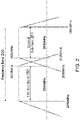
- Figure 2 illustrates an exemplary frequency band 200 with a first sub-band 202 and an adjacent second sub-band 204.
- the frequency band 200 is LTE band 41 which ranges from 2496 MHz to 2690MHz.
- the first sub-band 202 is from 2496MHz to 2570MHz.
- the second sub-band 204 is from 2630 to 2496MHz.
- the first sub-band 202 and the second sub-band are separated by a 60MHz guard band.
- the first sub-band 202 and the second sub-band 204 are respectively the uplink sub-band and the downlink sub-band for a frequency division duplexing band for another air interface, e.g. 3G UMTS.
- the first sub-band 202 is approximately uplink sub-band for 3G UMTS band 7
- the second sub-band 204 is approximately downlink sub-band for 3G UMTS band 7.
- the uplink sub-band for 3G UMTS band 7 is 2500MHz to 2570MHz.
- the downlink sub-band for 3G UMTS band 7 is 2620MHz to 2690MHz.
- the first sub-band 202 and the second sub-band 204 are used respectively by the small cell with selective filtering 104 and the backhaul wireless modem with selective filtering 106, or vice versa.
- the small cell with selective filtering 104 and the backhaul wireless modem with selective filtering 106 operate in TDD each transmitting when the other is receiving.
- selective filtering is used in each of the small cell and the backhaul wireless modem as will now be described.
- the selective filtering in a transceiver operating in a sub-band, provides enhanced filtering and suppression of undesired signals in the adjacent sub-band used by the other transceiver.
- FIG. 3 illustrates an exemplary small cell with selective filtering 300.
- the small cell with selective filtering 300 employs multiple-input multiple-output (MIMO) technology having two transmission channels and two reception channels.
- MIMO multiple-input multiple-output
- the small cell with selective filtering 300 may have more than two transmission channels and may have more than two reception channels.
- One transmission channel and one reception channel are coupled to a common antenna, through a transmit-receive switch, and to the first transceiver 305.
- the first transceiver 305 is also coupled to the transmit receive-switch, and is configured to select whether the antenna is connected to either the receive channel or the transmit channel depending upon whether the first transceiver 305 is transmitting or receiving.
- the first transceiver is also coupled to the backhaul wireless modem with selective filtering 106.
- the transmit-receive switches enable time domain duplexing operation by the small cell with selective filtering 300, and the subsequently described backhaul wireless modem with selective filtering 106.
- the transmit-receive switches must have sufficient insertion loss, isolation, and power compression to attain the design parameters for the transceiver in which the transmit-receive switches are used.
- the illustrated transmit-receive switches are single pole double throw (SPDT) switches.
- SPDT single pole double throw
- NPDT N pole double throw
- each transmit channel is comprised of a transmitter front end with selective filtering, and an upconverter and a baseband processor of the first transceiver 305.
- each receive channel is comprised of a receiver front end with selective filtering, and a downconverter and the baseband processor of the first transceiver 305.
- the exemplary small cell with selective filtering 300 comprises a first transmitter front end 302a and a second transmitter front end 302a, and a first receiver front end 304a and a second receiver front end 304a.
- the first transmitter front end 302a and the first receiver front end 304a are alternately coupled to a first antenna 316a.
- the second transmitter front end 302b and the second receiver front end 304b are alternately coupled to a second antenna 316b.
- the first transmitter front end 302a, the second transmitter front end 302b, the first receiver front end 304a, and the second receiver front end 304b are coupled to a first transceiver 305.
- the first transceiver 305 includes at least one baseband processor, at least one upconverter, and at least one downconverter. In another embodiment, e.g . for a first transceiver 305 implementing two MIMO transmit and two MIMO receive channels, the first transceiver 305 includes at least one baseband processor, two upconverters, and two downconverters. In another embodiment, the first transceiver 305 includes at least one baseband processor, two upconverters, and two downconverters.
- the output of the first transmitter front end 302a and the input of the first receiver front end 304a are respectively coupled to the first terminal and the second terminal of a first transmit-receive (TR) switch 312a.
- the output of the second transmitter front end 302b and the input of the second receiver front end 304b are respectively coupled to the first terminal and the second terminal of a second transmit-receive switch 312b.
- the first transmit-receive switch 312a and the second transmit-receive switch 312b are single pole double throw (SPDT) switches.
- the common terminals of the first transmit-receive switch 312a and second transmit-receive switch 312b are respectively coupled to a first antenna 316a and a second antenna 316b.
- the first transmit-receive switch 312a and the second transmit-receive switch 312b are respectively coupled to the first transceiver 305 by the first TR switch control line 330a and the second TR switch control line 330b.
- Control signals, from the first transceiver 305 are communicated over the first TR switch control line 330a and the second TR switch control line 330b, and respectively control the position of the first transmit-receive switch 312a and the second transmit-receive switch 312b to permit the small cell with selective filtering 300 to switch between transmitting and receiving to properly operate in time division duplexing mode.
- a first transmit signal 320a flows in the first transmitter front end 302a from the first transceiver 305 towards the first antenna 316a.
- a second transmit signal 320b flows respectively in the second transmitter front end 302b from the first transceiver 305 towards the second antenna 316b.
- a first receive signal 322a flows in the first receiver front end 304a to the first transceiver 305 away from the first antenna 316a.
- a second receive signal 322b flows respectively in the second receiver front end 304b to the first transceiver 305 away from the second antenna 316b.
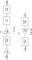
- each transmitter front end includes a power amplifier 408, a low pass filter (LPF) 410, and a first selective filter (SF) 416a.
- An input of the power amplifier 408 is coupled to an output of a transceiver, e.g . an output of an exciter in the transceiver.
- An output of the power amplifier 408 is coupled to an input of the low pass filter 410.
- An output of the low pass filter 410 is coupled to an input of the first selective filter 416a.
- the output of the first selective filter 416a is coupled to a transmission-receive switch.
- a buffer amplifier (BA) 414 is inserted between the transceiver and the power amplifier 408.
- the input of the buffer amplifier 414 is coupled to an output of the transceiver.
- the output of the buffer amplifier 414 is coupled to an input of the power amplifier 408.
- a second selective filter 416b is inserted between the transceiver and the power amplifier 408 to provide additional filtering and suppression of out of sub-band signals broadcast from the transceiver.
- the input of the second selective filter 416b is coupled to the output of either the buffer amplifier 414, if used, or alternatively to the output of the transceiver.
- the output of the second selective filter 416b is coupled to the input of the power amplifier 408.
- the second selective filter 416b can be employed to further suppress out-of-band noise, e.g . sideband noise, generated by the transmitter of a transceiver.
- the second selective filter 416b may be required if the transmitter front end has high gain which would amplify such noise.
- the one or more selective filters in the transmitter front end attenuate signals, broadcast by the transmitter of the transceiver and in the sub-band of the other transceiver, by at least fifty-five decibels.
- FIG 4B illustrates one embodiment of a receiver front end 430.
- each receiver front end includes a third selective filter 416c and a low noise amplifier 436.
- An output of the third selective filter 416c is coupled to an input of a low noise amplifier 436.
- An input of the third selective filter 416c is coupled to a transmit-receive switch.
- An output of the low noise amplifier 436 is coupled to an input of the transceiver, e.g . the input of a downconverter.
- a fourth selective filter 416d is coupled between the input of a transceiver and the output of the low noise amplifier 436 to provide enhanced filtering and suppression of out-of-band signals, e.g. from the adjacent transmitter.
- the selective filter(s) in the receiver front end attenuates signals, broadcast by and in the sub-band of the other transceiver, by at least fifty-five decibels.
- FIG. 5 illustrates an exemplary embodiment of a backhaul wireless modem with selective filtering 500.
- the exemplary backhaul wireless modem with selective filtering 500 employs multiple-input multiple-output (MIMO) technology having two transmission channels and four reception channels.
- MIMO multiple-input multiple-output
- the backhaul wireless modem with selective filtering 500 may have more than two transmission channels, and may have two or more than four reception channels.
- a multielement, e.g. eight elements, smart antenna having beam steering is used in lieu of the individual antennas in the backhaul wireless modem with selective filtering 500.
- Such beam steering increases equivalent isotropic receiver sensitivity and radiated power of the backhaul wireless modem with selective filtering 500
- Two pairs of transmission and reception channels are coupled to common antennas through transmit-receive switches, and to the second transceiver 505 in a manner similar to the illustration of Figure 3 .
- Two additional receiver front ends with selective filtering are used to provide extra link margin, and are also coupled to the second transceiver 505 and individual antennas.
- the implementations of the transmitter front ends and receiver front ends of the backhaul wireless modem with selective filtering 500 may be implemented as described above in Figures 4A and 4B .
- the second transceiver 505 includes at least one baseband processor, at least one upconverter, and at least one downconverter.
- the second transceiver 505 includes at least one baseband processor, two upconverters, and four downconverters.
- the second transceiver 505 is also coupled to the small cell with selective filtering 104.
- a third transmitter front end with selective filtering 502a has an input coupled to an output of the second transceiver 505, and an output coupled to a terminal of a third transmit-receive switch 512a.
- a third receiver front end with selective filtering 504a has an input coupled to another terminal of the third transmit-receive switch 512a, and an output coupled to an input of the second transceiver 505.
- the output of the third transmit-receive switch 512a is coupled to a third antenna 516a.
- a third TR switch control line 530a couples the second transceiver 505 to the third TR switch 512a to ensure proper time division duplexing operation.
- a fourth transmitter front end with selective filtering 502b has an input coupled to an output of the second transceiver 505, and an output coupled to a terminal of a fourth transmit-receive switch 512b.
- a fourth receiver front end with selective filtering 504b has an input coupled to another terminal of the fourth transmit-receive switch 512b, and an output coupled to an input of the second transceiver 505.
- the output of the fourth transmit-receive switch 512b is coupled to a fourth antenna 516b.
- a fourth TR switch control line 530b couples the second transceiver to the third TR switch 512a to ensure proper time division duplexing operation.
- a fifth receiver front end with selective filtering 504c has an input coupled to a fifth antenna 516c, and an output coupled to an input of the second transceiver 505.
- a sixth receiver front end with selective filtering 504d has an input coupled to a sixth antenna 516d, and an output coupled to an input of the second transceiver 505.
- a third transmit signal 520a flows in the third transmitter front end 502a from the second transceiver 505 towards the third antenna 516a.
- a fourth transmit signal 520b flows respectively in the fourth transmitter front end 502b from the second transceiver 505 towards the fourth antenna 516b.
- a third receive signal 522a flows in the third receiver front end 504a to the second transceiver 505 away from the third antenna 516a.
- a fourth receive signal 522b flows respectively in the fourth receiver front end 504b to the second transceiver 505 away from the fourth antenna 516b.
- a fifth receive signal 522c flows in the fifth receiver front end 504c to the second transceiver 505 away from the fifth antenna 516c.
- a sixth receive signal 522d flows in the sixth receiver front end 504d to the second transceiver 505 away from the sixth antenna 516d.
- each selective filter can be implemented with one filter, e.g. a band pass filter having a center frequency and corner frequencies, corresponding to the sub-band being used by the corresponding transceiver system in which the selective filtering is used.
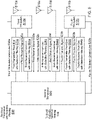
- FIG 6 illustrates another embodiment of a selective filter 600 which utilizes low cost, commercial off the shelf technology.
- the selective filter 600 includes a single pole double throw (SPDT) switch 604 coupled to a three-port filter 602.
- the SPDT switch 604 has two terminals 610a, 610b respectively coupled to two ports 608a, 608b, of the three-port filter 602, corresponding to different sub-bands.
- the SPDT switch 604 also has a common terminal 606b.
- the three-port filter 602 has a common port 606a.
- the common terminal 606b of the SPDT switch 604, and the common port 606a of the three-port filter 602, are the input /output terminals of the selective filter.
- the selective filter 600 is a reciprocal network the common terminal 606b and common port 606a can be used respectively as the input and output of the selective filter 600, or vice versa.
- the isolation between an unconnected terminal (i.e. not selected terminal) and the common terminal of the SPDT switch 604 in the adjacent sub-band is equal to or greater than the corresponding attenuation across the adjacent sub-band of the selective filter. This prevents the undesired out-of-band signals from leaking through the unselected terminal of the SPDT switch 604. Also, the insertion loss and power compression of the SPDT switch 604 should be sufficiently low and high to achieve the design of parameters the transceiver in which the SPDT switch 604 is used.
- the three-port filter 602 is a duplexer, such as a commercial off the shelf duplexer for 3G UMTS band 7. In another embodiment, the three-port filter 602 is a diplexer.
- Figure 7 illustrates one embodiment of a three-port filter 700.
- the three-port filter 700 comprises filter 1 702 and filter 2 704 having a common port 710, and unique ports 706, 708 for each filter.
- both filter 1 702 and filter 2 704 are bandpass filters, e.g. each having a center frequency and corner frequencies corresponding approximately to each sub-band.
- the filter corresponding to the higher frequency sub-band can be implemented with a high pass filter.
- the filter corresponding to the lower frequency sub-band can be implemented with a low pass filter.
- the SPDT switch 604 has a control terminal 612 which can be biased, e.g . by a voltage, to select which terminal 610a, 610b is coupled to the common terminal. This can be used select whether the selective filter 600 uses the filter corresponding to the upper or lower sub-band.
- one selective filter 600 can be manufactured for use in both the small cell with selective filtering 104 and the backhaul wireless modem with selective filtering 106.
- the control terminals 612 of each selective filter 600 is biased to select the one filter in one sub-band for the small cell with selective filtering 104 and the other filter in the second sub-band for the backhaul wireless modem with selective filtering 106.
- the control terminal 612 for the selective filters 600 in the small cell with selective filtering 104 are biased so that they use the filter having a center and corner frequencies about that sub-band.
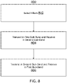
- Figure 8 illustrates one embodiment of operation of the exemplary communications network with selective filtering 100.
- select filters e.g. by biasing the control terminals 612 of the selective filters 600 used in the small cell with selective filtering 104 and the backhaul wireless modem with selective filtering 106.
- transmit a first signal in the first sub-band from the small cell with selective filtering 104 e.g. to user equipment 102; receive a second signal in the second sub-band at the backhaul wireless modem with selective filtering 106, e.g. from the macro cell 108.
- a signal may be a voltage signal or a current signal.
Landscapes
- Engineering & Computer Science (AREA)
- Signal Processing (AREA)
- Computer Networks & Wireless Communication (AREA)
- Power Engineering (AREA)
- Transceivers (AREA)
Claims (12)
- Kommunikationssystem, das in einem Frequenzband (200) arbeitet, umfassend:eine Basisstation, die eine kleine Zelle mit selektiver Filterung (104) bedient, wobei die Basisstation, die die kleine Zelle mit selektiver Filterung bedient, ein erstes Empfänger-Frontend (304a) und ein erstes Sender-Frontend (302a) umfasst, wobei das erste Sender-Frontend einen ersten selektiven Filter umfasst, wobei das erste Empfänger-Frontend einen zweiten selektiven Filter umfasst, wobei jeder von dem ersten selektiven Filter und dem zweiten selektiven Filter einen ersten Drei-Port-Filter (602) umfasst, der mit einem ersten einpoligen Wechselschalter (SPDT-Schalter) (604) gekoppelt ist, wobei der erste Drei-Port-Filter zwei Durchlassbänder umfasst, wobei eines der zwei Durchlassbänder in einem ersten Unterband liegt, und wobei der erste SPDT-Schalter in jedem von dem ersten selektiven Filter und dem zweiten selektiven Filter so eingestellt ist, dass er das erste Unterband auswählt;ein Backhaul-Funkmodem mit selektiver Filterung (106), das mit der Basisstation, die die kleine Zelle bedient, gekoppelt ist, wobei das Backhaul-Funkmodem mit selektiver Filterung ein zweites Empfänger-Frontend (504a) und ein zweites Sender-Frontend (502a) umfasst, wobei das zweite Sender-Frontend einen dritten selektiven Filter umfasst, wobei das zweite Empfänger-Frontend einen vierten selektiven Filter umfasst, wobei jeder von dem dritten selektiven Filter und dem vierten selektiven Filter einen zweiten Drei-Port-Filter (602) umfasst, der mit einem zweiten SPDT-Schalter (604) gekoppelt ist, wobei der zweite Drei-Port-Filter die zwei Durchlassbänder umfasst, und wobei der zweite SPDT-Schalter in jedem von dem dritten selektiven Filter und dem vierten selektiven Filter so eingestellt ist, dass er ein zweites Unterband auswählt;wobei die Basisstation, die die kleine Zelle mit selektiver Filterung bedient, so konfiguriert ist, dass sie nur in dem ersten Unterband (202) des Frequenzbands über eine erste Schnittstelle, die so konfiguriert ist, dass sie Kommunikationen mit einer Teilnehmervorrichtung (102) ermöglicht, sendet und empfängt, wenn das Backhaul-Funkmodem mit selektiver Filterung entsprechend in dem zweiten Unterband (204) des Frequenzbands über eine zweite Schnittstelle, die so konfiguriert ist, dass sie Kommunikationen mit einer Makrozelle (108) ermöglicht, empfängt und sendet;wobei das Backhaul-Funkmodem mit selektiver Filterung so konfiguriert ist, dass es nur in dem zweiten Unterband sendet und empfängt, wenn die Basisstation, die die kleine Zelle bedient, entsprechend in dem ersten Unterband empfängt und sendet; undwobei das erste Unterband und das zweite Unterband benachbart sind.
- Kommunikationssystem nach Anspruch 1, wobei die Basisstation, die die kleine Zelle mit selektiver Filterung bedient, und das Backhaul-Funkmodem mit selektiver Filterung durch eine Ethernet-Verbindung gekoppelt sind.
- Kommunikationssystem nach Anspruch 1, wobei die Basisstation, die die kleine Zelle mit selektiver Filterung bedient, und das Backhaul-Funkmodem mit selektiver Filterung zusammengepackt sind.
- Kommunikationssystem nach Anspruch 1, wobei die Basisstation, die die kleine Zelle mit selektiver Filterung bedient, und das Backhaul-Funkmodem mit selektiver Filterung jeweils zumindest zwei Empfangskanäle und zumindest zwei Übertragungskanäle aufweisen.
- Kommunikationssystem nach Anspruch 1, wobei die Basisstation, die die kleine Zelle mit selektiver Filterung bedient, ferner umfasst:einen ersten Transceiver;das erste Sender-Frontend mit selektiver Filterung, das mit dem ersten Transceiver gekoppelt ist;das erste Empfänger-Frontend mit selektiver Filterung, das mit dem ersten Transceiver gekoppelt ist;einen ersten Sende-Empfangs-Schalter, der mit dem ersten Sender-Frontend mit selektiver Filterung und dem ersten Empfänger-Frontend mit selektiver Filterung gekoppelt ist;zumindest eine Antenne, die mit dem ersten Sende-Empfangs-Schalter gekoppelt ist; undwobei der erste Sende-Empfangs-Schalter konfiguriert ist, eine Antenne entweder mit dem ersten Empfänger-Frontend mit selektiver Filterung oder mit dem ersten Sender-Frontend mit selektiver Filterung zu verbinden, abhängig davon, ob die Basisstation, die die kleine Zelle mit selektiver Filterung bedient, empfängt oder sendet.
- Kommunikationssystem nach Anspruch 5, wobei das erste Sender-Frontend mit selektiver Filterung ferner umfasst:einen Leistungsverstärker (408), der mit dem ersten Transceiver gekoppelt ist;einen Tiefpassfilter (410), der mit dem Leistungsverstärker gekoppelt ist; undwobei der erste selektive Filter (416a) mit dem Tiefpassfilter und dem ersten Sende-Empfangs-Schalter gekoppelt ist.
- Kommunikationssystem nach Anspruch 6, wobei das Empfänger-Frontend mit selektiver Filterung ferner einen rauscharmen Verstärker (436) umfasst, der mit dem zweiten selektiven Filter und dem ersten Transceiver gekoppelt ist.
- Kommunikationssystem nach Anspruch 6, wobei der erste selektive Filter ein Duplexer ist.
- Kommunikationssystem nach Anspruch 6, wobei der erste selektive Filter umfasst:einen ersten Drei-Port-Filter (700) mit drei Ports und zwei Filtern;einen ersten einpoligen Wechselschalter (SPDT-Schalter) mit zwei Anschlüssen, einem gemeinsamen Anschluss und einem Steueranschluss;wobei zwei Ports des ersten Drei-Port-Filters mit den zwei Anschlüssen des ersten SPDT-Schalters gekoppelt sind; undwobei der erste SPDT-Schalter konfiguriert ist, einen der zwei Filter des ersten Drei-Port-Filters basierend auf einem Signal auszuwählen, das an den Steueranschluss des ersten SPDT-Schalters angelegt wird.
- Kommunikationssystem nach Anspruch 6, wobei der zweite Filter ein Duplexer ist.
- Kommunikationssystem nach Anspruch 6, wobei das Empfänger-Frontend mit selektiver Filterung ferner einen rauscharmen Verstärker umfasst, der mit dem zweiten selektiven Filter und dem ersten Transceiver gekoppelt ist.
- Verfahren zum Betreiben der Basisstation, die die kleine Zelle bedient, und des Backhaul-Funkmodems nach Anspruch 1, umfassend:Senden, ausgehend von der Basisstation, die die kleine Zelle bedient, auf dem ersten Unterband;wenn die Basisstation, die die kleine Zelle bedient, sendet, Empfangen, auf dem Backhaul-Funkmodem, das mit der kleinen Zelle gekoppelt ist, auf dem zweiten Unterband in dem Frequenzband;Empfangen, auf der Basisstation, die die kleine Zelle bedient, auf dem ersten Unterband; undwenn die Basisstation, die die kleine Zelle bedient, empfängt, Senden, ausgehend von dem Backhaul-Funkmodem, auf dem zweiten Unterband.
Applications Claiming Priority (2)
| Application Number | Priority Date | Filing Date | Title |
|---|---|---|---|
| US201662435515P | 2016-12-16 | 2016-12-16 | |
| PCT/US2017/063455 WO2018111534A1 (en) | 2016-12-16 | 2017-11-28 | Method and apparatus for operating co-located transceivers on the same frequency band |
Publications (3)
| Publication Number | Publication Date |
|---|---|
| EP3556027A1 EP3556027A1 (de) | 2019-10-23 |
| EP3556027A4 EP3556027A4 (de) | 2020-08-19 |
| EP3556027B1 true EP3556027B1 (de) | 2022-10-05 |
Family
ID=62559167
Family Applications (1)
| Application Number | Title | Priority Date | Filing Date |
|---|---|---|---|
| EP17880141.1A Not-in-force EP3556027B1 (de) | 2016-12-16 | 2017-11-28 | Verfahren und vorrichtung zum betreiben von benachbarten sendeempfängern auf demselben frequenzband |
Country Status (4)
| Country | Link |
|---|---|
| US (1) | US10567151B2 (de) |
| EP (1) | EP3556027B1 (de) |
| CN (1) | CN110235391B (de) |
| WO (1) | WO2018111534A1 (de) |
Families Citing this family (1)
| Publication number | Priority date | Publication date | Assignee | Title |
|---|---|---|---|---|
| EP3556027B1 (de) * | 2016-12-16 | 2022-10-05 | Commscope Technologies LLC | Verfahren und vorrichtung zum betreiben von benachbarten sendeempfängern auf demselben frequenzband |
Family Cites Families (46)
| Publication number | Priority date | Publication date | Assignee | Title |
|---|---|---|---|---|
| DE69842089D1 (de) * | 1998-11-30 | 2011-02-17 | Sony Deutschland Gmbh | Dualbandsende-Empfänger |
| US6865169B1 (en) * | 1999-11-02 | 2005-03-08 | Ipwireless, Inc. | Cellular wireless internet access system using spread spectrum and internet protocol |
| CA2323881A1 (en) * | 2000-10-18 | 2002-04-18 | Dps Wireless Inc. | Adaptive personal repeater |
| US7289494B2 (en) * | 2001-12-06 | 2007-10-30 | Pulse-Link, Inc. | Systems and methods for wireless communication over a wide bandwidth channel using a plurality of sub-channels |
| US8204036B2 (en) * | 2007-02-28 | 2012-06-19 | Motorola Mobility, Inc. | Method and apparatus for coexistence |
| JP5134016B2 (ja) * | 2007-03-02 | 2013-01-30 | クゥアルコム・インコーポレイテッド | 信号品質を向上させるためのオンライン中継器と連携した適応アンテナアレイの使用 |
| WO2008147269A1 (en) * | 2007-05-31 | 2008-12-04 | Telefonaktiebolaget Lm Ericsson (Publ) | Method and system of communications |
| WO2009014764A1 (en) * | 2007-07-25 | 2009-01-29 | Teenay Wireless, Inc. | A multi-tier backhaul network system with traffic differentiation and advanced processing capabilities and methods therefor |
| US8023886B2 (en) * | 2007-09-28 | 2011-09-20 | Broadcom Corporation | Method and system for repeater with gain control and isolation via polarization |
| US7729724B2 (en) * | 2007-11-19 | 2010-06-01 | Broadcom Corporation | RF front-end and applications thereof |
| KR101485977B1 (ko) * | 2007-11-21 | 2015-01-23 | 삼성전자주식회사 | 전이중 중계방식을 기반으로 하는 이동통신 시스템에서자원할당을 위한 프레임 구조, 방법 및 장치 |
| US8457549B2 (en) * | 2008-02-29 | 2013-06-04 | Lingna Holdings Pte., Llc | Multi-user MIMO relay protocol with self-interference cancellation |
| KR101457704B1 (ko) * | 2008-06-19 | 2014-11-04 | 엘지전자 주식회사 | 무선 송수신기와 이를 구비한 중계국 |
| US8761824B2 (en) * | 2008-06-27 | 2014-06-24 | Qualcomm Incorporated | Multi-carrier operation in a wireless communication network |
| US8594008B2 (en) * | 2008-11-18 | 2013-11-26 | Qualcomm Incorporated | Relay communications methods and apparatus |
| CN102362448B (zh) * | 2008-11-26 | 2015-11-25 | 安德鲁无线系统有限责任公司 | 用于中继多输入多输出信号的单输入单输出中继器 |
| US20100234071A1 (en) * | 2009-03-12 | 2010-09-16 | Comsys Communication & Signal Processing Ltd. | Vehicle integrated communications system |
| US8849186B2 (en) * | 2009-05-12 | 2014-09-30 | Qualcomm Incorporated | Repeater communication using inserted low power sequences |
| US8305941B2 (en) * | 2009-09-02 | 2012-11-06 | Cohen Allen S | Broadband combining system with high spectrum efficiency for use in wireless communications |
| US8718542B2 (en) * | 2009-09-23 | 2014-05-06 | Powerwave Technologies S.A.R.L. | Co-location of a pico eNB and macro up-link repeater |
| WO2011102631A2 (en) * | 2010-02-16 | 2011-08-25 | Lg Electronics Inc. | Relay node apparatus for transmitting and receiving signal according to link operation mode in wireless communication system and method thereof |
| IT1398534B1 (it) * | 2010-02-25 | 2013-03-01 | Wisytech S R L | Apparecchiatura per sistema di telecomunicazione a femtocelle. |
| WO2011131242A1 (en) * | 2010-04-22 | 2011-10-27 | Telefonaktiebolaget L M Ericsson (Publ) | Multi-antenna device |
| CN102986268B (zh) * | 2010-05-03 | 2017-04-26 | 瑞典爱立信有限公司 | 将系统信息改变传播到中继 |
| CN102377470B (zh) * | 2010-08-13 | 2015-08-12 | 中兴通讯股份有限公司 | 可重配置无线节点及与宏小区无线接入点协同工作的方法 |
| US9185711B2 (en) * | 2010-09-14 | 2015-11-10 | Qualcomm Incorporated | Method and apparatus for mitigating relay interference |
| US9882628B2 (en) * | 2010-10-29 | 2018-01-30 | Telefonaktiebolaget Lm Ericsson (Publ) | Self-interference suppression control for a relay node |
| WO2012059555A1 (en) * | 2010-11-03 | 2012-05-10 | Telefonaktiebolaget L M Ericsson (Publ) | Self-interference suppression in full-duplex mimo relays |
| US9154987B2 (en) * | 2010-12-30 | 2015-10-06 | Nokia Solutions And Networks Oy | Relay-to-relay interference coordination in a wireless communication network |
| US20120224472A1 (en) * | 2011-03-04 | 2012-09-06 | Electronics And Telecommunications Research Institute | Method for relaying of base station, method for relaying of terminal and method for transmitting |
| EP2742748A4 (de) * | 2011-08-12 | 2015-08-26 | Intel Corp | System und verfahren zur uplink-leistungssteuerung in einem drahtlosen kommunikationssystem |
| US9185684B2 (en) * | 2011-09-14 | 2015-11-10 | Marvell World Trade Ltd | Using non-uniform frequency bands for coexistence among multiple wireless communication technologies |
| US8934398B2 (en) * | 2011-10-07 | 2015-01-13 | Qualcomm Incorporated | System, apparatus, and method for repeater pilot signal generation in wireless communication systems |
| US20130143483A1 (en) * | 2011-12-06 | 2013-06-06 | Qualcomm Incorporated | Maintaining repeater stability in a multi-repeater scenario |
| KR20130090669A (ko) * | 2012-02-06 | 2013-08-14 | 삼성전자주식회사 | 이종 네크워크에서 셀간 간섭을 조정하는 중앙집중형 스케쥴링 방법 및 장치 |
| US9001712B2 (en) * | 2012-05-02 | 2015-04-07 | Texas Instruments Incorporated | Transmit signal cancelation apparatus and methods |
| US8995312B2 (en) * | 2012-12-21 | 2015-03-31 | Hcl Technologies Limited | Multi-channel broadband re-configurable RF front end for software defined radio / cognitive radio |
| JP6492327B2 (ja) * | 2013-09-25 | 2019-04-03 | ソニー株式会社 | 通信制御装置、通信制御方法、無線通信装置及び無線通信方法 |
| CN106031219B (zh) * | 2014-02-17 | 2020-01-14 | 瑞典爱立信有限公司 | 无线回程链路的处理 |
| CN104883202B (zh) * | 2014-02-27 | 2018-05-29 | 华为技术有限公司 | 一种减少邻频干扰的方法及中继设备 |
| US20170055304A1 (en) * | 2014-04-28 | 2017-02-23 | Telefonaktiebolaget Lm Ericsson (Publ) | Connection establishment in a wireless backhaul network |
| US10038471B2 (en) * | 2015-01-27 | 2018-07-31 | Electronics And Telecommunications Research Institute | Method and apparatus for canceling self-interference |
| US10111206B2 (en) * | 2016-05-09 | 2018-10-23 | Cisco Technology, Inc. | Directing client devices between co-located macro and micro wireless cells |
| US10498521B2 (en) * | 2016-08-31 | 2019-12-03 | Skyworks Solutions, Inc. | Switched-filter duplexing architecture for front-end systems |
| EP3556027B1 (de) * | 2016-12-16 | 2022-10-05 | Commscope Technologies LLC | Verfahren und vorrichtung zum betreiben von benachbarten sendeempfängern auf demselben frequenzband |
| EP4236107A3 (de) * | 2017-04-07 | 2023-10-18 | CommScope Technologies LLC | Ausgangsstummschaltung für aktive verstärkersysteme |
-
2017
- 2017-11-28 EP EP17880141.1A patent/EP3556027B1/de not_active Not-in-force
- 2017-11-28 CN CN201780084593.6A patent/CN110235391B/zh not_active Expired - Fee Related
- 2017-11-28 WO PCT/US2017/063455 patent/WO2018111534A1/en not_active Ceased
- 2017-12-15 US US15/844,410 patent/US10567151B2/en active Active
Also Published As
| Publication number | Publication date |
|---|---|
| EP3556027A4 (de) | 2020-08-19 |
| WO2018111534A1 (en) | 2018-06-21 |
| US20180175998A1 (en) | 2018-06-21 |
| US10567151B2 (en) | 2020-02-18 |
| CN110235391B (zh) | 2020-12-08 |
| EP3556027A1 (de) | 2019-10-23 |
| CN110235391A (zh) | 2019-09-13 |
Similar Documents
| Publication | Publication Date | Title |
|---|---|---|
| US12081498B2 (en) | Channelization for signal boosters | |
| US12407402B2 (en) | Time division duplex (TDD) network protection repeater | |
| US12082094B2 (en) | Communication by a repeater system including a network of radio frequency repeater devices | |
| KR101852894B1 (ko) | 안테나 스위칭 시스템 및 방법 | |
| US9154171B2 (en) | Reconfigurable radio frequency circuits and methods of receiving | |
| US9191098B2 (en) | Capability reporting for relay nodes in wireless networks | |
| EP2664184B1 (de) | Bandbreitenkonfiguration und meldung für relaisverbindungen | |
| US9236930B2 (en) | Methods and apparatus for antenna tuning | |
| CN108292948A (zh) | 信号增强器的信道化 | |
| US20240163773A1 (en) | Method for access control, relay terminal and network device | |
| CN116390242B (zh) | 无线通信系统中的智能中继器的控制信息 | |
| CN118489290A (zh) | 节点的网络整合方法和装置 | |
| EP3556027B1 (de) | Verfahren und vorrichtung zum betreiben von benachbarten sendeempfängern auf demselben frequenzband | |
| EP3944514B1 (de) | Zeitmultiplex-duplex(tdd)-netzschutzverstärker | |
| US20240356720A1 (en) | Communication apparatus and communication method | |
| US20240137106A1 (en) | Operating and/or configuring a repeater device for enabling the repeater device to be operated together with a user equipment |
Legal Events
| Date | Code | Title | Description |
|---|---|---|---|
| STAA | Information on the status of an ep patent application or granted ep patent |
Free format text: STATUS: THE INTERNATIONAL PUBLICATION HAS BEEN MADE |
|
| PUAI | Public reference made under article 153(3) epc to a published international application that has entered the european phase |
Free format text: ORIGINAL CODE: 0009012 |
|
| STAA | Information on the status of an ep patent application or granted ep patent |
Free format text: STATUS: REQUEST FOR EXAMINATION WAS MADE |
|
| 17P | Request for examination filed |
Effective date: 20190624 |
|
| AK | Designated contracting states |
Kind code of ref document: A1 Designated state(s): AL AT BE BG CH CY CZ DE DK EE ES FI FR GB GR HR HU IE IS IT LI LT LU LV MC MK MT NL NO PL PT RO RS SE SI SK SM TR |
|
| AX | Request for extension of the european patent |
Extension state: BA ME |
|
| DAV | Request for validation of the european patent (deleted) | ||
| DAX | Request for extension of the european patent (deleted) | ||
| A4 | Supplementary search report drawn up and despatched |
Effective date: 20200716 |
|
| RIC1 | Information provided on ipc code assigned before grant |
Ipc: H04B 1/401 20150101ALI20200710BHEP Ipc: H04B 7/26 20060101ALI20200710BHEP Ipc: H04B 7/155 20060101AFI20200710BHEP |
|
| GRAP | Despatch of communication of intention to grant a patent |
Free format text: ORIGINAL CODE: EPIDOSNIGR1 |
|
| STAA | Information on the status of an ep patent application or granted ep patent |
Free format text: STATUS: GRANT OF PATENT IS INTENDED |
|
| INTG | Intention to grant announced |
Effective date: 20220107 |
|
| GRAJ | Information related to disapproval of communication of intention to grant by the applicant or resumption of examination proceedings by the epo deleted |
Free format text: ORIGINAL CODE: EPIDOSDIGR1 |
|
| STAA | Information on the status of an ep patent application or granted ep patent |
Free format text: STATUS: REQUEST FOR EXAMINATION WAS MADE |
|
| INTC | Intention to grant announced (deleted) | ||
| GRAP | Despatch of communication of intention to grant a patent |
Free format text: ORIGINAL CODE: EPIDOSNIGR1 |
|
| STAA | Information on the status of an ep patent application or granted ep patent |
Free format text: STATUS: GRANT OF PATENT IS INTENDED |
|
| INTG | Intention to grant announced |
Effective date: 20220422 |
|
| GRAS | Grant fee paid |
Free format text: ORIGINAL CODE: EPIDOSNIGR3 |
|
| GRAA | (expected) grant |
Free format text: ORIGINAL CODE: 0009210 |
|
| STAA | Information on the status of an ep patent application or granted ep patent |
Free format text: STATUS: THE PATENT HAS BEEN GRANTED |
|
| AK | Designated contracting states |
Kind code of ref document: B1 Designated state(s): AL AT BE BG CH CY CZ DE DK EE ES FI FR GB GR HR HU IE IS IT LI LT LU LV MC MK MT NL NO PL PT RO RS SE SI SK SM TR |
|
| REG | Reference to a national code |
Ref country code: GB Ref legal event code: FG4D |
|
| REG | Reference to a national code |
Ref country code: CH Ref legal event code: EP |
|
| REG | Reference to a national code |
Ref country code: AT Ref legal event code: REF Ref document number: 1523411 Country of ref document: AT Kind code of ref document: T Effective date: 20221015 |
|
| REG | Reference to a national code |
Ref country code: IE Ref legal event code: FG4D |
|
| REG | Reference to a national code |
Ref country code: DE Ref legal event code: R096 Ref document number: 602017062481 Country of ref document: DE |
|
| REG | Reference to a national code |
Ref country code: LT Ref legal event code: MG9D |
|
| PGFP | Annual fee paid to national office [announced via postgrant information from national office to epo] |
Ref country code: GB Payment date: 20221128 Year of fee payment: 6 Ref country code: DE Payment date: 20221125 Year of fee payment: 6 |
|
| REG | Reference to a national code |
Ref country code: NL Ref legal event code: MP Effective date: 20221005 |
|
| REG | Reference to a national code |
Ref country code: AT Ref legal event code: MK05 Ref document number: 1523411 Country of ref document: AT Kind code of ref document: T Effective date: 20221005 |
|
| PG25 | Lapsed in a contracting state [announced via postgrant information from national office to epo] |
Ref country code: NL Free format text: LAPSE BECAUSE OF FAILURE TO SUBMIT A TRANSLATION OF THE DESCRIPTION OR TO PAY THE FEE WITHIN THE PRESCRIBED TIME-LIMIT Effective date: 20221005 |
|
| PG25 | Lapsed in a contracting state [announced via postgrant information from national office to epo] |
Ref country code: SE Free format text: LAPSE BECAUSE OF FAILURE TO SUBMIT A TRANSLATION OF THE DESCRIPTION OR TO PAY THE FEE WITHIN THE PRESCRIBED TIME-LIMIT Effective date: 20221005 Ref country code: PT Free format text: LAPSE BECAUSE OF FAILURE TO SUBMIT A TRANSLATION OF THE DESCRIPTION OR TO PAY THE FEE WITHIN THE PRESCRIBED TIME-LIMIT Effective date: 20230206 Ref country code: NO Free format text: LAPSE BECAUSE OF FAILURE TO SUBMIT A TRANSLATION OF THE DESCRIPTION OR TO PAY THE FEE WITHIN THE PRESCRIBED TIME-LIMIT Effective date: 20230105 Ref country code: LT Free format text: LAPSE BECAUSE OF FAILURE TO SUBMIT A TRANSLATION OF THE DESCRIPTION OR TO PAY THE FEE WITHIN THE PRESCRIBED TIME-LIMIT Effective date: 20221005 Ref country code: FI Free format text: LAPSE BECAUSE OF FAILURE TO SUBMIT A TRANSLATION OF THE DESCRIPTION OR TO PAY THE FEE WITHIN THE PRESCRIBED TIME-LIMIT Effective date: 20221005 Ref country code: ES Free format text: LAPSE BECAUSE OF FAILURE TO SUBMIT A TRANSLATION OF THE DESCRIPTION OR TO PAY THE FEE WITHIN THE PRESCRIBED TIME-LIMIT Effective date: 20221005 Ref country code: AT Free format text: LAPSE BECAUSE OF FAILURE TO SUBMIT A TRANSLATION OF THE DESCRIPTION OR TO PAY THE FEE WITHIN THE PRESCRIBED TIME-LIMIT Effective date: 20221005 |
|
| PG25 | Lapsed in a contracting state [announced via postgrant information from national office to epo] |
Ref country code: RS Free format text: LAPSE BECAUSE OF FAILURE TO SUBMIT A TRANSLATION OF THE DESCRIPTION OR TO PAY THE FEE WITHIN THE PRESCRIBED TIME-LIMIT Effective date: 20221005 Ref country code: PL Free format text: LAPSE BECAUSE OF FAILURE TO SUBMIT A TRANSLATION OF THE DESCRIPTION OR TO PAY THE FEE WITHIN THE PRESCRIBED TIME-LIMIT Effective date: 20221005 Ref country code: LV Free format text: LAPSE BECAUSE OF FAILURE TO SUBMIT A TRANSLATION OF THE DESCRIPTION OR TO PAY THE FEE WITHIN THE PRESCRIBED TIME-LIMIT Effective date: 20221005 Ref country code: IS Free format text: LAPSE BECAUSE OF FAILURE TO SUBMIT A TRANSLATION OF THE DESCRIPTION OR TO PAY THE FEE WITHIN THE PRESCRIBED TIME-LIMIT Effective date: 20230205 Ref country code: HR Free format text: LAPSE BECAUSE OF FAILURE TO SUBMIT A TRANSLATION OF THE DESCRIPTION OR TO PAY THE FEE WITHIN THE PRESCRIBED TIME-LIMIT Effective date: 20221005 Ref country code: GR Free format text: LAPSE BECAUSE OF FAILURE TO SUBMIT A TRANSLATION OF THE DESCRIPTION OR TO PAY THE FEE WITHIN THE PRESCRIBED TIME-LIMIT Effective date: 20230106 |
|
| REG | Reference to a national code |
Ref country code: CH Ref legal event code: PL |
|
| REG | Reference to a national code |
Ref country code: DE Ref legal event code: R097 Ref document number: 602017062481 Country of ref document: DE |
|
| REG | Reference to a national code |
Ref country code: BE Ref legal event code: MM Effective date: 20221130 |
|
| PG25 | Lapsed in a contracting state [announced via postgrant information from national office to epo] |
Ref country code: SM Free format text: LAPSE BECAUSE OF FAILURE TO SUBMIT A TRANSLATION OF THE DESCRIPTION OR TO PAY THE FEE WITHIN THE PRESCRIBED TIME-LIMIT Effective date: 20221005 Ref country code: RO Free format text: LAPSE BECAUSE OF FAILURE TO SUBMIT A TRANSLATION OF THE DESCRIPTION OR TO PAY THE FEE WITHIN THE PRESCRIBED TIME-LIMIT Effective date: 20221005 Ref country code: MC Free format text: LAPSE BECAUSE OF FAILURE TO SUBMIT A TRANSLATION OF THE DESCRIPTION OR TO PAY THE FEE WITHIN THE PRESCRIBED TIME-LIMIT Effective date: 20221005 Ref country code: LI Free format text: LAPSE BECAUSE OF NON-PAYMENT OF DUE FEES Effective date: 20221130 Ref country code: EE Free format text: LAPSE BECAUSE OF FAILURE TO SUBMIT A TRANSLATION OF THE DESCRIPTION OR TO PAY THE FEE WITHIN THE PRESCRIBED TIME-LIMIT Effective date: 20221005 Ref country code: DK Free format text: LAPSE BECAUSE OF FAILURE TO SUBMIT A TRANSLATION OF THE DESCRIPTION OR TO PAY THE FEE WITHIN THE PRESCRIBED TIME-LIMIT Effective date: 20221005 Ref country code: CZ Free format text: LAPSE BECAUSE OF FAILURE TO SUBMIT A TRANSLATION OF THE DESCRIPTION OR TO PAY THE FEE WITHIN THE PRESCRIBED TIME-LIMIT Effective date: 20221005 Ref country code: CH Free format text: LAPSE BECAUSE OF NON-PAYMENT OF DUE FEES Effective date: 20221130 |
|
| PLBE | No opposition filed within time limit |
Free format text: ORIGINAL CODE: 0009261 |
|
| STAA | Information on the status of an ep patent application or granted ep patent |
Free format text: STATUS: NO OPPOSITION FILED WITHIN TIME LIMIT |
|
| PG25 | Lapsed in a contracting state [announced via postgrant information from national office to epo] |
Ref country code: SK Free format text: LAPSE BECAUSE OF FAILURE TO SUBMIT A TRANSLATION OF THE DESCRIPTION OR TO PAY THE FEE WITHIN THE PRESCRIBED TIME-LIMIT Effective date: 20221005 Ref country code: LU Free format text: LAPSE BECAUSE OF NON-PAYMENT OF DUE FEES Effective date: 20221128 Ref country code: AL Free format text: LAPSE BECAUSE OF FAILURE TO SUBMIT A TRANSLATION OF THE DESCRIPTION OR TO PAY THE FEE WITHIN THE PRESCRIBED TIME-LIMIT Effective date: 20221005 |
|
| 26N | No opposition filed |
Effective date: 20230706 |
|
| PG25 | Lapsed in a contracting state [announced via postgrant information from national office to epo] |
Ref country code: IE Free format text: LAPSE BECAUSE OF NON-PAYMENT OF DUE FEES Effective date: 20221128 |
|
| PG25 | Lapsed in a contracting state [announced via postgrant information from national office to epo] |
Ref country code: SI Free format text: LAPSE BECAUSE OF FAILURE TO SUBMIT A TRANSLATION OF THE DESCRIPTION OR TO PAY THE FEE WITHIN THE PRESCRIBED TIME-LIMIT Effective date: 20221005 Ref country code: FR Free format text: LAPSE BECAUSE OF NON-PAYMENT OF DUE FEES Effective date: 20221205 Ref country code: BE Free format text: LAPSE BECAUSE OF NON-PAYMENT OF DUE FEES Effective date: 20221130 |
|
| PG25 | Lapsed in a contracting state [announced via postgrant information from national office to epo] |
Ref country code: HU Free format text: LAPSE BECAUSE OF FAILURE TO SUBMIT A TRANSLATION OF THE DESCRIPTION OR TO PAY THE FEE WITHIN THE PRESCRIBED TIME-LIMIT; INVALID AB INITIO Effective date: 20171128 |
|
| PG25 | Lapsed in a contracting state [announced via postgrant information from national office to epo] |
Ref country code: CY Free format text: LAPSE BECAUSE OF FAILURE TO SUBMIT A TRANSLATION OF THE DESCRIPTION OR TO PAY THE FEE WITHIN THE PRESCRIBED TIME-LIMIT Effective date: 20221005 |
|
| PG25 | Lapsed in a contracting state [announced via postgrant information from national office to epo] |
Ref country code: MK Free format text: LAPSE BECAUSE OF FAILURE TO SUBMIT A TRANSLATION OF THE DESCRIPTION OR TO PAY THE FEE WITHIN THE PRESCRIBED TIME-LIMIT Effective date: 20221005 Ref country code: IT Free format text: LAPSE BECAUSE OF FAILURE TO SUBMIT A TRANSLATION OF THE DESCRIPTION OR TO PAY THE FEE WITHIN THE PRESCRIBED TIME-LIMIT Effective date: 20221005 |
|
| REG | Reference to a national code |
Ref country code: DE Ref legal event code: R119 Ref document number: 602017062481 Country of ref document: DE |
|
| GBPC | Gb: european patent ceased through non-payment of renewal fee |
Effective date: 20231128 |
|
| PG25 | Lapsed in a contracting state [announced via postgrant information from national office to epo] |
Ref country code: BG Free format text: LAPSE BECAUSE OF FAILURE TO SUBMIT A TRANSLATION OF THE DESCRIPTION OR TO PAY THE FEE WITHIN THE PRESCRIBED TIME-LIMIT Effective date: 20221005 |
|
| PG25 | Lapsed in a contracting state [announced via postgrant information from national office to epo] |
Ref country code: MT Free format text: LAPSE BECAUSE OF FAILURE TO SUBMIT A TRANSLATION OF THE DESCRIPTION OR TO PAY THE FEE WITHIN THE PRESCRIBED TIME-LIMIT Effective date: 20221005 |
|
| PG25 | Lapsed in a contracting state [announced via postgrant information from national office to epo] |
Ref country code: DE Free format text: LAPSE BECAUSE OF NON-PAYMENT OF DUE FEES Effective date: 20240601 |
|
| PG25 | Lapsed in a contracting state [announced via postgrant information from national office to epo] |
Ref country code: GB Free format text: LAPSE BECAUSE OF NON-PAYMENT OF DUE FEES Effective date: 20231128 |
|
| PG25 | Lapsed in a contracting state [announced via postgrant information from national office to epo] |
Ref country code: GB Free format text: LAPSE BECAUSE OF NON-PAYMENT OF DUE FEES Effective date: 20231128 Ref country code: DE Free format text: LAPSE BECAUSE OF NON-PAYMENT OF DUE FEES Effective date: 20240601 |
|
| PG25 | Lapsed in a contracting state [announced via postgrant information from national office to epo] |
Ref country code: TR Free format text: LAPSE BECAUSE OF FAILURE TO SUBMIT A TRANSLATION OF THE DESCRIPTION OR TO PAY THE FEE WITHIN THE PRESCRIBED TIME-LIMIT Effective date: 20221005 |