US8204036B2 - Method and apparatus for coexistence - Google Patents
Method and apparatus for coexistence Download PDFInfo
- Publication number
- US8204036B2 US8204036B2 US11/680,067 US68006707A US8204036B2 US 8204036 B2 US8204036 B2 US 8204036B2 US 68006707 A US68006707 A US 68006707A US 8204036 B2 US8204036 B2 US 8204036B2
- Authority
- US
- United States
- Prior art keywords
- map
- signal
- symbol
- map symbol
- expected
- Prior art date
- Legal status (The legal status is an assumption and is not a legal conclusion. Google has not performed a legal analysis and makes no representation as to the accuracy of the status listed.)
- Active, expires
Links
Images


Classifications
-
- H—ELECTRICITY
- H04—ELECTRIC COMMUNICATION TECHNIQUE
- H04W—WIRELESS COMMUNICATION NETWORKS
- H04W88/00—Devices specially adapted for wireless communication networks, e.g. terminals, base stations or access point devices
- H04W88/02—Terminal devices
- H04W88/06—Terminal devices adapted for operation in multiple networks or having at least two operational modes, e.g. multi-mode terminals
-
- H—ELECTRICITY
- H04—ELECTRIC COMMUNICATION TECHNIQUE
- H04B—TRANSMISSION
- H04B1/00—Details of transmission systems, not covered by a single one of groups H04B3/00 - H04B13/00; Details of transmission systems not characterised by the medium used for transmission
- H04B1/38—Transceivers, i.e. devices in which transmitter and receiver form a structural unit and in which at least one part is used for functions of transmitting and receiving
- H04B1/40—Circuits
- H04B1/401—Circuits for selecting or indicating operating mode
-
- H—ELECTRICITY
- H04—ELECTRIC COMMUNICATION TECHNIQUE
- H04L—TRANSMISSION OF DIGITAL INFORMATION, e.g. TELEGRAPHIC COMMUNICATION
- H04L27/00—Modulated-carrier systems
- H04L27/26—Systems using multi-frequency codes
- H04L27/2601—Multicarrier modulation systems
- H04L27/2647—Arrangements specific to the receiver only
-
- H—ELECTRICITY
- H04—ELECTRIC COMMUNICATION TECHNIQUE
- H04W—WIRELESS COMMUNICATION NETWORKS
- H04W72/00—Local resource management
- H04W72/12—Wireless traffic scheduling
- H04W72/1215—Wireless traffic scheduling for collaboration of different radio technologies
Definitions
- This disclosure relates generally to coexistence of two different synchronous frame-based wireless communication technologies and more specifically to operation of Bluetooth and Orthogonal Frequency Division Multiple Access (OFDMA) radios on the same device at the same (or nearly the same) frequency band.
- OFDMA Orthogonal Frequency Division Multiple Access
- Coexistence refers to the ability for multiple wireless protocols to operate in or around the same frequency band without significant degradation to either's operation.
- IEEE 802.16e wireless metropolitan area network communications sometimes referred to as WiMAX
- IEEE 802.11b/g wireless local area network communications sometimes referred to as WiFi
- IEEE 802.15 wireless personal area network communications sometimes referred to as Bluetooth
- ISM Industrial, Scientific, and Medical
- two or more radio transceivers operating in or around the same band may cause internal interference. Transmitting using one technology at a frequency band while receiving using the other technology at the same or similar frequency band will lead to adjacent channel interference and receiver de-sense. Because IEEE 802.11b/g framing is asynchronous Ethernet-based and Bluetooth Synchronous Connection Oriented (SCO) framing for voice communication is synchronous, it is possible for the mobile station to delay IEEE 802.11b/g transmissions to a point in time when the mobile station's Bluetooth receiver is not active and thus reduce internal interference.
- SCO Bluetooth Synchronous Connection Oriented
- IEEE 802.16e uses synchronous framing and Bluetooth SCO links also use synchronous framing, there is little flexibility to delay one technology's transmission relative to the other technology's reception.
- packet losses can be as high as 25% on the downlink (from a base station, or access point, to the mobile station) and 38% on the uplink (from the mobile station to the base station or access point).
- Bluetooth communications on the unlicensed 2.4-2.5 GHz ISM band should not consistently degrade IEEE 802.16e communications on the licensed Multichannel Multipoint Distribution Service (MMDS) and Instructional Television Fixed Service (IFTS) bands at 2.5-2.7 GHz in the United States or IEEE 802.16e communications in the 2.3 GHz band in Canada, South Korea, and United States.
- MMDS Multichannel Multipoint Distribution Service
- IFTS Instructional Television Fixed Service
- FIG. 1 shows an example of a system diagram having a dual mode WiMAX/CDMA phone with Bluetooth.
- FIG. 2 shows a diagram of IEEE 802.16e (WiMAX) downlink frames, IEEE 802.16 (Bluetooth) frames, and associated signals.
- WiMAX WiMAX
- Bluetooth IEEE 802.16
- FIG. 3 shows a co-existence predictor that can be used to determine when to shut down a Bluetooth transmitter.
- FIG. 4 shows a flow chart for operation of an observer unit of the co-existence predictor shown in FIG. 3 .
- FIG. 5 shows a flow diagram for detecting MAP symbols using transition analysis of a receiver-enable (RXE) signal.
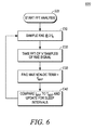
- FIG. 6 shows a flow diagram for finding MAP symbols within an RXE signal that uses Fast Fourier Transform (FFT) techniques.
- FFT Fast Fourier Transform
- FIG. 7 shows a sample diagram of analysis performed by the FFT block shown in FIG. 3 operating in accordance with the flow diagram shown in FIG. 6 .
- FIG. 8 shows a simple graphical example of an observed RXE signal and an expected MAP pattern P.
- FIG. 9 shows a graph of cross-correlation between the observed RXE signal and the expected MAP pattern P of FIG. 8 .
- FIG. 10 shows a derivative graph of the cross-correlation shown in FIG. 9 .
- FIG. 11 shows a graph of cross-correlation maximum versus the expected MAP pattern P as a percentage.
- FIG. 12 shows a flow diagram of a covariance method for finding MAP symbols within an RXE signal.
- FIG. 13 shows a diagram of a DLL process gradually locking onto MAP symbols.
- FIG. 14 provides a flow diagram for operation of a DLL block within an observer unit of a co-existence predictor as shown in FIG. 3 .
- FIG. 15 shows a flow diagram that can be implemented in the Decision Logic Unit (DLU) of the co-existence predictor of FIG. 3 .
- DLU Decision Logic Unit
- a method for coexistence of an orthogonal frequency division multiple access (OFDMA) receiver with a synchronous frame-based transmitter takes an estimated media access protocol (MAP′) signal indicating when a MAP message is expected to be received by the OFDMA receiver and sends the MAP′ signal to the synchronous frame-based transmitter to shut down the synchronous frame-based transmitter when a MAP message is expected to be received.
- MAP′ estimated media access protocol
- a frequency, phase, and duration of a future MAP symbol can be determined from an OFDMA receiver-enable (RXE) signal by using techniques such as microcontroller unit interrupt measurements, Fast Fourier Transform, cross-correlation, and/or symbol timing recovery such as delay-locked loop.
- RXE OFDMA receiver-enable
- One type of OFDMA system is a WiMAX system in accordance with IEEE 802.16e. Because a single frame size is commonly used today for WiMAX systems (and one MAP message is contained at the beginning of each WiMAX frame), the frequency of the MAP′ signal could alternately be predetermined. Additionally, estimates of future MAP symbol duration could be predetermined based on the type of OFMDA link (e.g., video, voice, data) and/or historical MAP symbol duration information.
- the type of OFMDA link e.g., video, voice, data
- a co-existence predictor that could be used to implement the above method has an observer unit for determining historical MAP symbol frequency, duration, and phase from an RXE signal provided by the OFDMA receiver, an estimator unit for predicting future MAP symbols, and a decision logic unit for producing a shut down signal to the synchronous frame-based transmitter when future MAP symbols are expected.
- the synchronous frame-based transmitter By using the MAP′ signal to control shut down of the synchronous frame-based transmitter, the synchronous frame-based transmitter will not cause internal interference with the OFDMA receiver during expected receipt of MAP messages. Reliable receipt of MAP messages allows the OFDMA receiver to maintain synchronization with an external OFDMA transmitter.
- the decision logic unit may also choose to shut down the synchronous frame-based transmitter depending on the relative priorities of frames being transmitted by the synchronous frame-based transmitter and downlink data expected to be received by the OFDMA receiver.
- WiMAX is an OFDMA communication technology
- Bluetooth SCO is a synchronous frame-based communication technology.
- the co-existence predictor and its method supports WiMAX and Bluetooth coexistence by reducing the risk that internal interference will cause the loss of a MAP message. This solution also provides a balance between successful receipt of important WiMAX packets and successful transmission of Bluetooth packets.
- FIG. 1 shows an example of a system diagram 100 including a mobile station 110 having OFDMA radio transceiver 117 operating at a first frequency band, a Bluetooth Wireless Personal Area Network (WPAN) radio transceiver 115 operating at a second frequency band near the first frequency band, and a Wireless Wide Area Network (WWAN) radio transceiver 112 operating at a third frequency band far from the first frequency band.
- the WWAN radio transceiver 112 is implemented as a Code Division Multiple Access (CDMA) user equipment transceiver operating at 1900 MHz; although the WWAN radio could alternately be Wideband-CDMA (W-CDMA), CDMA2000, Global System for Mobile Communications (GSM), Time Division Multiple Access (TDMA), or other protocols operating at other frequency bands.
- CDMA Code Division Multiple Access
- GSM Global System for Mobile Communications
- TDMA Time Division Multiple Access
- the CDMA radio transceiver 112 of the mobile station 110 uses a first wireless communication link 125 at 1900 MHz to communicate with a CDMA base station 120 .
- This example presumes that the first communication link 125 handles a full-duplex voice call (circuit-switched connection) including speech encoded with Enhanced Variable Rate Codec (EVRC) technology.
- EVRC Enhanced Variable Rate Codec
- the speech is transcoded with Continuous Variable Slope Delta (CVSD) modulation to be sent using the Bluetooth transceiver 115 over a second wireless communication link 145 at 2.4 GHz to the Bluetooth headset 140 .
- Bluetooth uses Synchronous Connection Oriented (SCO) links for voice where timeslots are fixed and packets are not re-transmitted.
- SCO Synchronous Connection Oriented
- the OFDMA transceiver 117 is an IEEE 802.16e transceiver operating at 2.5 GHz, which will require coexistence with the Bluetooth transceiver operating at 2.4 GHz.
- the OFDMA transceiver 117 could alternately be implemented as a UTRA-UTRAN Longer Term Evolution (LTE) transceiver, a Multiband OFDM Alliance (MBOA) ultra-wide band (UWB) transceiver, or any other OFDMA synchronous framing system operating in the same or adjacent band as the Bluetooth transceiver.
- LTE Longer Term Evolution
- MBOA Multiband OFDM Alliance
- UWB ultra-wide band
- the Bluetooth transceiver 115 will be controlled through a Bluetooth shutdown signal 190 to reduce internal interference, receiver de-sense, and packet collisions.
- Variations of this system diagram 100 may exclude the WWAN first communication link 125 at 1900 MHz, because it is not a cause of interference at the first and second frequency bands (2.4-2.5 GHz). For example, if a user had a video streaming third wireless communication link 135 at 2.5 GHz and was listening to the stereo audio portion retransmitted over the Bluetooth second wireless communication link 145 at 2.4 GHz, this would require coexistence. Also, if a user had a Voice over Internet Protocol (VoIP) third wireless communication link 135 at 2.5 GHz and was listening to the voice using the Bluetooth headset, this too would also require coexistence.
- VoIP Voice over Internet Protocol
- the mobile station 110 can protect the OFDMA receiver 117 from internal interference when an important OFDMA message is expected to be received.
- the Bluetooth transmitter can be controlled depending on the relative importance of any Bluetooth message to be transmitted and any OFDMA data to be received.
- FIG. 2 shows a diagram of IEEE 802.16e frames 210 (which will also be called WiMAX frames for ease of reference), IEEE 802.15 frames 270 (which will be also called Bluetooth frames), and associated signals.
- WiMAX is an example of an OFDMA system.
- Other OFDMA systems include UTRAN-LTE and MBOA-UWB.
- a single WiMAX frame 220 , 240 has three major components: a Media Access Protocol (MAP) message 222 , 242 at the beginning, followed first by a downlink sub-frame 225 , 245 and then an uplink sub-frame 227 , 247 .
- the MAP message 222 , 242 is variable in duration and changes as the number of scheduled users changes.
- the size of the MAP message 222 , 242 may change slightly from one WiMAX frame to the next.
- the overall duration of a single WiMAX frame 220 , 240 is 5 milliseconds
- Section 11.18.1 and Table 384a of IEEE Standard 802.16e specify eight possible WiMAX frame durations ranging from 2 milliseconds to 20 milliseconds.
- MAP messages 222 , 242 are important to IEEE 802.16e (and other types of OFDMA) system performance because a MAP message 222 , 242 is used to allocate active downlink OFDMA symbols 231 on the current WiMAX frame 220 and active uplink OFDMA symbols 236 on the next WiMAX frame 240 .
- the end of a downlink sub-frame and the beginning of an uplink sub-frame can vary from one WiMAX frame to the next, and MAP messages are important for maintaining synchronization between a mobile station and an access point (sometimes referred to as a base station). If a MAP message is lost, then a mobile station will not know when to listen for downlink data and when to transmit uplink data on the next WiMAX frame.
- a MAP indicator signal 255 indicates when a MAP message 222 , 242 is expected to be received.
- the MAP indicator signal 255 includes a sequence of MAP symbols 260 , which have a periodicity (frequency and phase) and slowly-varying duration 256 .
- a MAP symbol has an active pulse of a MAP duration 256 and a non-active “tail” to complete the MAP symbol.
- the MAP symbol indicates when a MAP message is being received (i.e., during the active pulse of the MAP symbol) and when no MAP message is being received (i.e., during the inactive “tail” of the MAP symbol).
- Signal 255 can be used directly as the Bluetooth shutdown signal 190 ( FIG. 1 ) and control the Bluetooth radio transmitter. Thus, when signal 255 is active, the Bluetooth radio transmitter is off. This prevents the Bluetooth transmitter from creating internal interference while the OFDMA receiver will be receiving a MAP message. Allowing the Bluetooth receiver to remain functional lets the Adaptive Frequency Hopping (AFH) algorithm contained in the Bluetooth device to continue its channel interference analysis. Optionally, on some designs, it may be advantageous to simply disable the entire Bluetooth transceiver while receiving the MAP message.
- AMFH Adaptive Frequency Hopping
- a MAP indicator signal 255 is not available, several methods can be used to construct a MAP′ signal from a WiMAX receiver-enable (RXE) signal 252 to create a Bluetooth shutdown signal 190 for the Bluetooth radio transceiver that reduces interference and yet allows for reliable reception of MAP messages without totally undermining Bluetooth communications.
- the RXE signal 252 is high whenever the OFDMA receiver is active. Thus, the RXE signal 252 is high during the MAP message of every WiMAX frame and also during active downlink sub-frames such as downlink sub-frame 231 .
- the RXE signal 252 shown in FIG. 2 goes high during every MAP message, which occurs in this example every 5 milliseconds for about 504 microseconds.
- the RXE signal 252 also goes high during downlink data reception, which is not as consistent in frequency or duration as the MAP messages.
- the transmitter-enable (TXE) signal 257 is activated during a transmission portion of the uplink sub-frame, corresponding to active uplink OFDMA symbols 236 in this example.
- TXE signal 257 activation does not occur as often as the MAP portion of the RXE signal 252 because MAP messages are monitored even in sleep mode when there is no uplink data to transmit.
- a WiMAX frame 240 has a MAP message 242 followed by a downlink sub-frame 245 and then an uplink sub-frame 247 , a pulse in the TXE signal 257 (corresponding to uplink symbol 236 in this example) will be followed-in-time by a pulse on the RXE signal 252 which indicates a MAP message.
- TTG Transmit Transition Gap
- RTG Receive Transition Gap
- FIG. 2 also shows a diagram of Bluetooth frames 270 aligned arbitrarily in time with WiMAX frames 210 .
- Each Bluetooth frame 280 , 290 lasts 3.75 milliseconds and has a maximum of six timeslots 281 , 282 , 283 , 284 , 285 , 286 , 291 , 292 , 293 , 294 , 295 , 296 that alternate between the master and slave every 625 microseconds.
- the Bluetooth timeslots 281 , 283 , 285 , 291 , 293 , 295 labeled with an ‘M’ are the possible transmissions of the Bluetooth transceiver 115 ( FIG.
- the Bluetooth transceiver 115 When a Bluetooth master timeslot 285 aligns with an active portion of the RXE signal 252 , the Bluetooth transceiver 115 will cause interference with the WiMAX transceiver's 117 receptions. Conversely, when a Bluetooth slave timeslot 294 aligns with an active portion of the TXE signal 257 , the WiMAX transceiver 117 will interfere with the Bluetooth transceiver's 115 receptions.
- the Bluetooth transceiver 115 In order to minimize interference between Bluetooth transmissions and WiMAX receptions (and vice versa) as shown at Bluetooth timeslots 285 , 294 , the Bluetooth transceiver 115 ( FIG. 1 ) will be shut down using a Bluetooth shutdown signal 190 when WiMAX MAP messages are expected and possibly also at times when WiMAX downlink data is expected.
- FIG. 3 shows a co-existence predictor 300 that can be used to determine when to shut down a Bluetooth transceiver 115 ( FIG. 1 ) in the absence of a MAP indicator signal 255 ( FIG. 2 ).
- the co-existence predictor 300 uses the RXE signal 252 ( FIG. 2 ) of the OFDMA transceiver 117 ( FIG. 1 ) to produce a BT_SHDN signal 390 that can be used as the Bluetooth shutdown signal 190 ( FIG. 1 ).
- the predictor can optionally use the TXE signal 257 in conjunction with the RXE signal 252 to produce a BT_SHDN signal 390 .
- the co-existence predictor 300 includes an observer unit 320 , an estimator unit 350 , and a decision logic unit (DLU) 370 .
- the observer unit 320 monitors the RXE signal 252 from a coexistent OFDMA transceiver 117 and analyzes its periodicity (frequency and phase) and pulse duration looking for embedded MAP symbols representing receipt of MAP messages. Because MAP messages are periodic and do not vary quickly in duration, the estimator unit 350 can take the historical MAP symbol information from the observer unit 320 and generate a MAP′ signal representing the expected location-in-time of future MAP symbols.
- the decision logic unit 370 generates the BT_SHDN signal 390 based on the MAP′ signal and an optional BT_PRI signal 394 that indicates when a priority Bluetooth packet will be transmitted.
- the observer unit 320 can include one or more components used to extract MAP symbols from an RXE signal 252 .
- a microcontroller unit 321 , a Fast Fourier Transform block 322 , a delay-locked loop 325 , and/or a covariance block 327 can be used to find the frequency, phase, and duration of a MAP symbol.
- FIG. 4 shows a flow chart 400 for operation of the observer unit 320 of the co-existence predictor 300 shown in FIG. 3 .
- the observer unit 320 starts observing the RXE signal 252 (shown in FIG. 2 and FIG. 3 ).
- step 420 performs MAP symbol detection.
- a high RXE signal for a MAP message is indistinguishable from a high RXE signal for downlink data receipt, over time the observer unit 320 can detect a periodic high RXE signal of fairly consistent duration and hypothesize a MAP symbol.
- step 430 activates a locking mechanism to verify whether the next expected MAP symbol (based on the previous possible MAP symbols) has arrived on the RXE signal as expected. If the RXE signal is active at the time(s) predicted by the locking mechanism, step 440 locks to the MAP symbols on the RXE signal. The flow chart ends with step 499 .
- MAP symbol detection step 420 can be implemented in an observer unit 320 in a number of ways.
- One simple but processor-intensive method takes samples of the RXE signal 252 for a predetermined period of time, notes transitions from low-to-high and high-to-low, and looks for a common pattern in the transitions to hypothesize as MAP symbols.
- Another method uses a Fast Fourier Transform to find the most-common periodic symbol to hypothesize as a MAP symbol.
- a third method uses a delay-locked loop to find a common symbol's frequency and phase, which is then hypothesized as the MAP symbol.
- a fourth method uses covariance analysis to match an expected MAP symbol pattern with the RXE signal.
- FIG. 5 shows a flow diagram 500 for detecting MAP symbols using transition analysis of an RXE signal 252 ( FIG. 2 ).
- the flow diagram 500 can be implemented as part of MAP symbol detection step 420 ( FIG. 4 ) by a microcontroller unit (MCU) 321 ( FIG. 3 ) with interrupt-driven methods and programmable timers.
- MCU microcontroller unit
- step 510 waits for the TXE signal to be low.
- the first transition of the RXE signal from high-to-low is sampled in step 520 .
- Step 530 stores the time of the high-to-low transition in memory.
- step 550 determines the frequency and phase of the MAP symbols from the statistical mode of the time period between high-to-low transitions of the RXE signal stored in memory. The method ends at step 599 .
- MAP messages are expected to produce the most periodic pulse within an RXE signal (even when there are one or more sleep frames within the observation period), finding the most common high-to-low transition period should produce the hypothetical MAP symbol and not select the less-periodic active downlink symbols. Additionally, by modifying the flow diagram to note both low-to-high transitions as well as high-to-low transitions, the MAP symbol duration can be found by measuring the length of time the hypothetical MAP pulse is high before the high-to-low transitions hypothesized to be part of MAP symbols.
- FIG. 6 shows a flow diagram 600 of another method for finding a MAP symbol within an RXE signal 252 (shown in FIG. 2 and FIG. 3 ) that uses Fast Fourier Transform (FFT) techniques.
- the flow diagram 600 can be implemented as part of MAP symbol detection step 420 ( FIG. 4 ).
- An observer unit 320 FIG. 3
- step 610 samples an RXE signal 252 .
- the RXE signal 252 is sampled at twice the Nyquist frequency f S , which is the inverse of half the shortest OFDMA symbol duration.
- Step 620 takes the Fast Fourier Transform of a predetermined number ‘x’ of samples of the RXE signal.
- Step 630 estimates that the highest-amplitude non-DC term of the FFT indicates the MAP symbol frequency and phase. Given that a 5 millisecond WiMAX frame is ubiquitous currently, a MAP symbol should usually occur every 5 milliseconds.
- step 640 compares the f MAP returned from the FFT block 322 with known frame and sleep durations and tests across a subset of MAP periods, T MAP , to enhance the periodic analysis performed by the FFT block 322 .
- the steps in the flow diagram 600 can be repeated as necessary to confirm the hypothetical MAP symbol frequency and phase within an RXE signal.
- FIG. 7 shows a sample frequency and phase diagrams 710 , 750 of analysis performed by the FFT block 322 shown in FIG. 3 operating in accordance with the flow diagram 600 shown in FIG. 6 .
- the x-axis 720 displays frequency and the y-axes 730 , 740 display amplitude and phase (respectively) of a frequency analysis of an RXE signal 252 .
- the frequency and phase of the hypothetical MAP symbol is determined by selecting the most frequent periodic symbol 760 .
- the FFT block 322 finds the MAP symbol frequency and the FFT block 322 can be used to distinguish between different WiMAX frame durations and sleep intervals.
- a covariance (CoVAR) block 327 can discern the presence of a hypothetical MAP symbol within an RXE signal 252 .
- the CoVAR block 327 works by observing an incoming RXE signal for a period of time and calculating a correlation between the incoming RXE signal and a predetermined signal chosen to best represent an expected MAP signal. Processing by the CoVAR block 327 can be conducted on a group of RXE signal samples.
- the correlation between the RXE signal 252 and a shifting expected MAP pattern P can be computed for every shift k according to the following formula.
- a recursive (real-time) method can be used to calculate ⁇ k based on a previously calculated value of ⁇ k-1 .
- the output of the CoVAR block 327 can be used to determine periodicity, indicating the frequency and phase of a MAP symbol in the observed RXE signal.
- the derivative, or slope, of the correlation function can be used to initiate locking onto a MAP signal when the sign of the derivative changes.
- the calculated correlation coefficients with a global extremum can also be used in conjunction with a delayed-lock loop (DLL) to lock onto the maximum correlation.
- DLL delayed-lock loop
- FIG. 8 shows a simple graphical example 800 of an observed RXE signal 852 and an expected MAP pattern P 890 .
- the RXE signal 852 is 25 milliseconds long and contains a MAP symbol of 504 microseconds duration at the beginning of each 5 millisecond frame plus active downlink pulses at various other times.
- the given MAP symbol pattern P 890 is a 25 millisecond sequence of MAP symbols having a duration of 504 microseconds and repeating every 5 milliseconds.
- equation (1) produces a cross-correlation graph similar to the one shown in FIG. 9 .
- FIG. 9 shows a cross-correlation graph 900 where the x-axis 910 represents the number of shifts from 0 to a predetermined maximum of 120 (taking 120 as an example) and where the y-axis 920 represents the magnitude of the cross-correlation.
- the results 950 of the cross-correlation of the observed 25 milliseconds of the incoming RXE signal 852 with the expected MAP symbol pattern P 890 peaks at point 960 , which is at shift 64, and indicates that the MAP symbols indicated in the RXE signal 852 lag behind the timing of the expected MAP symbol pattern P by 64 shifts (or leads the expected MAP pattern P by 56 shifts). Even if there had been sleep frames within the observed RXE signal, there would still be a peak where the cross-correlation of the expected MAP symbol pattern P best matches the observed RXE signal.
- FIG. 10 shows a cross-correlation derivative graph 1000 where the x-axis 1010 represents the number of shifts from 0 to a predetermined maximum of 120 (taking 120 as an example) and the y-axis 1020 represents the magnitude of the derivative of the cross-correlation results shown in FIG. 9 .
- the sign S of the derivative results 1050 changes to negative at point 1060 , which happens to be at 64 shifts.
- the sign S of the derivative may change at a point that is different from (or the same as) the peak in the cross-correlation graph 900 .
- the duration of a MAP symbol within the RXE signal is not necessarily constant although current implementations generally result in MAP symbol durations of about 504 microseconds and sometimes tens of microseconds more. Duration, also, can be estimated for an observed RXE signal using covariance analysis.
- the value at the peak 960 ( FIG. 9 ) of the cross-correlation results 950 can be used to estimate the duration of the hypothetical MAP symbols as a percentage of the duration of the high pulses in the expected MAP pattern P 890 ( FIG. 8 ).
- FIG. 11 shows a graph 1100 of cross-correlation maximum versus the expected MAP pattern P as a percentage of the downlink sub-frame.
- X-axis 1110 represents the percentage of a downlink sub-frame while y-axis 1120 shows the peak values of the cross-correlation graph.
- the peak value at point 960 is approximately 0.9. This indicates a very high peak cross-correlation value and thus the duration of a MAP symbol in the RXE signal can be estimated to be 100% of the duration of a MAP symbol within the expected MAP pattern P.
- the duration of a MAP symbol in the RXE signal is estimated to be only 50% of the duration of a MAP symbol within the expected MAP pattern P.
- this graph 1100 presumes no sleep intervals within the observed RXE signal or the expected MAP pattern P, different covariance graphs can be constructed for different patterns of sleep intervals by selecting expected MAP patterns incorporating various sleep intervals. The covariance graph with a highest peak cross-correlation value will indicate the closest expected MAP pattern.
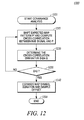
- FIG. 12 shows a flow diagram 1200 of this covariance method for finding a MAP symbol within an RXE signal 252 (shown in FIG. 2 and FIG. 3 ).
- the flow diagram 1200 can be implemented as part of MAP symbol detection step 420 ( FIG. 4 ).
- An observer unit 320 ( FIG. 3 ) can use a CoVAR block 327 to find MAP symbol frequency, phase, and/or duration.
- the method starts when start step 1201 selects an expected MAP pattern P.
- This expected MAP pattern P can be selected from one or more expected MAP patterns stored within the mobile station 110 ( FIG. 1 ) based on one or more factors such as: historical frequency of success by the mobile station 110 in detecting MAP symbols using a particular expected MAP pattern, a preset order for using expected MAP patterns, knowledge of the type of OFDMA link currently active (e.g., VoIP, internet, etc.), and/or any known connection setup or sleep interval information.
- Step 1210 shifts the given MAP pattern P a preset number of times (e.g., 120 times) and computes a cross-correlation between a given portion of the RXE signal and P.
- Step 1220 determines the derivative sign S of the cross-correlation.
- the peak value of the cross-correlation function can be used to estimate the hypothetical MAP symbol duration and sample offset in step 1240 .
- the flow diagram 1200 ends in step 1299 . If periodicity cannot be detected after a predefined number of expected MAP pattern P shifts, the algorithm exits abnormally and may restart at step 1201 and select another expected MAP pattern P.
- a covariance technique provides yet another alternate method for observing a MAP symbol in an RXE signal.
- the locking mechanism can be activated in step 430 .
- the peak magnitude of the cross-correlation results will not be as high—unless an expected MAP pattern has the same sleep pattern.
- the general results will still occur, and the shift number where the cross-correlation derivative goes negative in amplitude will indicate when the locking mechanism should be activated.
- DLL delayed-lock loop
- FIG. 13 shows a diagram 1300 of a DLL process gradually locking onto MAP symbols.
- the x-axis 1310 shows milliseconds and the y-axis 1320 shows amplitude.
- the convolution creates triangle peaks 1341 , 1342 that are separated by zero intervals 1343 , 1344 .
- Zeros of the slope of the convolution graph occur either at the peak of a triangle or during the zero intervals between triangles.
- Three samples taken around a preliminary MAP period T MAP (x 1 being early, x 2 being on-time, and x 3 being late) can be used iteratively adjust the MAP period T MAP to find the MAP frequency.
- the slopes between the samples are analyzed to determine whether to extend or decrease the MAP period for the next three samples to be taken around the new MAP period. For example, at the first sampling point 1331 shown, three samples are taken. Because the graph is rising around sampling point 1331 , the MAP period is lengthened, and the next sampling point 1332 is the lengthened MAP period away from the previous sampling point 1331 . Around sampling point 1332 , the slopes are all zero because the sampling point 1332 is in a zero interval between triangles. Then the MAP period is changed again because the DLL has not found a maximum of the convolution. The next sampling point 1333 results in negative slopes among the three-sample set, indicating that the MAP period should be shortened.
- the MAP period is successively shortened, resulting in sampling points 1334 , 1335 , 1336 which draw closer and closer to the peaks of the convolution graph.
- sampling point 1337 When the sampling point 1337 is reached, the samples on either side of point 1337 have a positive slope followed by a negative slope, indicating at least a local extremum.
- this diagram 1300 reflects an RXE signal 252 ( FIG. 2 and FIG. 3 ) containing both a MAP symbol at peak 1431 and a downlink data symbol at peak 1342 .
- the MAP symbol corresponds exactly to the matched filter
- the amplitude of the MAP symbol peak 1341 is 1.
- the downlink data symbol does not correspond exactly to the matched filter and so the amplitude of the peak 1342 is less than 1.
- the example here is fairly simple, note that the downlink data symbol is not as consistent as the MAP symbol in either time or magnitude; thus any temporary lock on a downlink data peak 1342 will eventually be overcome by future iterations the DLL.
- a sample value of 1 (or close to 1), with equal values that are less than 1 immediately before and after the on-time sample x 2 , indicates that a portion of the RXE signal matches exactly with the expected MAP symbol represented by the matched filter and provides an indication that the MAP symbol in the RXE signal has been located.
- the MAP period is kept stable now and the last sample shown, at point 1338 (taken with a MAP period equal to the preceding MAP period used to find point 1337 ), also has a value of 1 which indicates that the DLL has locked onto a T MAP that accurately reflects the timing of the MAP symbol within the RXE signal.
- FIG. 14 provides a flow diagram 1400 for operation of a DLL block 325 within an observer unit 320 of a co-existence predictor 300 as shown in FIG. 3 .
- This flow diagram 1400 can be situated within step 420 of FIG. 4 as being another additional or alternate method for detecting a MAP symbol.
- step 1410 obtains an initial expected MAP symbol periodicity T MAP , which is the inverse of the frequency of an expected MAP symbol.
- This expected MAP symbol periodicity T MAP can be selected from one or more expected MAP symbol periodicity values stored within the mobile station 110 ( FIG. 1 ) based on one or more factors such as: historical frequency of success by the mobile station 110 in detecting MAP symbols using a particular expected MAP symbol periodicity, a preset order for using expected MAP symbol periodicity values, knowledge of the type of OFDMA link currently active (e.g., VoIP, internet, etc.), and/or FFT analysis. For example, because most WiMAX frames are 5 milliseconds in length, selecting an initial T MAP of 5 milliseconds is reasonable.
- step 1420 the expected MAP symbol is fed into an averaging matched filter (MF) of a DLL (sometimes an MF is considered as “preceding” a DLL rather than being part of the DLL), and the DLL will convolve the expected MAP symbol and the observed RXE signal to produce triangle peaks.
- MF averaging matched filter
- MAP_Length represents the duration of the hypothetical MAP symbol.
- Optional steps 1452 , 1455 , 1457 examine the TXE signal 257 ( FIG. 2 and FIG. 3 ) and determine whether T MAP should be increased by MAP_Length or decreased by MAP_Length. If the TXE signal is active as determined by step 1452 (NO branch), then a MAP symbol will be expected soon. (This is because a WiMAX frame has a MAP message followed by downlink sub-frames and then uplink sub-frames. Thus, uplink data will be followed by a MAP message. See FIG. 2 .) Because a MAP symbol is expected soon, step 1457 causes step 1460 to decrease the MAP interval by the MAP_Length value. If the TXE signal is not active, step 1455 causes step 1460 to increase the MAP interval by the MAP_Length.
- step 1470 determines if m 3 does not equal zero. If m 3 does not equal zero, this indicates that there is an overall slope within the three samples and the MAP interval is gradually increased or decreased depending on the sign of the overall slope m 3 using step 1480 .
- the change in the MAP interval produced by step 1480 is slight (e.g., ⁇ 2 represents one sampling interval) when the change in the MAP interval produced by step 1460 is greater (e.g., MAP_Length represents more than one sampling interval).
- step 1490 maintains the same MAP interval for the next iteration through the flow diagram 1400 . If the extremum found is not the global maximum, then it results from a downlink OFDMA data symbol. Because downlink OFDMA data symbols are not as periodic as MAP symbols, the consistent T MAP will eventually fail to produce an indicator of a local maximum (i.e., either step 1450 will result in a YES decision or step 1470 will result in a YES decision) and the DLL will proceed to find another local maximum.
- the MAP symbol duration and/or MAP symbol periodicity (frequency and phase) outputs of the observer unit 320 are used as inputs to the estimator unit 350 to generate a MAP′ signal (estimating the timing and duration of future MAP symbols).
- the DLU 370 uses the MAP′ signal, plus the actual RXE signal from the OFDMA transceiver 117 , to control shutdown of the Bluetooth transmitter within Bluetooth transceiver 115 (or any other transmitter, such as a WiFi transmitter, that has potential contention issues).
- FIG. 15 shows a flow diagram 1500 that can be implemented in the DLU 370 of the co-existence predictor 300 of FIG. 3 .
- the DLU 370 operates to protect the OFMDA receiver 117 ( FIG. 1 ) and shuts down the co-located Bluetooth transmitter 115 whenever MAP messages are expected as indicated by the MAP′ signal from the estimator unit 350 . Also, when an active OFDMA downlink symbol is expected, the DLU 370 prioritizes the OFDMA receiver over the Bluetooth transmitter unless the Bluetooth transmitter has a high priority signal. If, however, the Bluetooth priority signal has been high for a predetermined amount of time, the OFDMA receiver is temporarily prioritized so that at least some incoming OFDMA data can be received.
- the DLU checks whether a Bluetooth priority signal BT_PRI is active in step 1510 . If the BT_PRI signal is active as determined by step 1520 , the DLU checks whether a downlink counter has reached a threshold in step 1530 , increments the downlink counter in step 1540 if the threshold has not been reached, and couples the MAP′ signal to the BT_SHDN pin in step 1550 so that Bluetooth communication is only interrupted when MAP messages are expected. If a Bluetooth transmission is halted, the data will be lost if it is using an SCO connection. (If the Bluetooth transceiver is using a fast ARQ mechanism, it will be retransmitted at the next available timeslot.)
- the BT_PRI signal is configurable and the BT_PRI signal for Bluetooth/WiMAX co-existence can differ from its definition for Bluetooth/WLAN co-existence.
- step 1520 determines that the Bluetooth priority signal BT_PRI is not active, the DLU 370 couples the RXE signal to the BT_SHDN pin in step 1570 to protect all WiMAX downlink traffic as well as the MAP messages.
- the method and apparatus for coexistence reduces internal interference between a Bluetooth transmitter and an OFDMA receiver both operating at (or near) a single frequency band in a single mobile station.
- Coexistence is promoted by protecting MAP messages and balancing the relative priorities of receiving OFDMA downlink data symbols and transmitting Bluetooth timeslots.
- a signal indicating expected MAP message receipt can be directly generated by an OFDMA transceiver or an RXE signal can be analyzed by a co-existence predictor to determine expected MAP message receipt times.
Landscapes
- Engineering & Computer Science (AREA)
- Computer Networks & Wireless Communication (AREA)
- Signal Processing (AREA)
- Mobile Radio Communication Systems (AREA)
Abstract
Description
where k changes from 1 to a predetermined maximum number of shifts. For the examples to be shown, the predetermined maximum number of shifts is selected to be 120. Thus, the cross-correlation between RXE and P is calculated for every shift of the expected MAP pattern P.
Claims (20)
Priority Applications (7)
| Application Number | Priority Date | Filing Date | Title |
|---|---|---|---|
| US11/680,067 US8204036B2 (en) | 2007-02-28 | 2007-02-28 | Method and apparatus for coexistence |
| KR1020097017893A KR101089482B1 (en) | 2007-02-28 | 2008-02-11 | Method and apparatus for coexistence |
| PCT/US2008/053555 WO2008106302A2 (en) | 2007-02-28 | 2008-02-11 | Method and apparatus for coexistence |
| EP08729504.4A EP2140579B1 (en) | 2007-02-28 | 2008-02-11 | Method and apparatus for coexistence |
| CN2008800066196A CN101622802B (en) | 2007-02-28 | 2008-02-11 | Method and apparatus for coexistence |
| BRPI0808115-8A BRPI0808115B1 (en) | 2007-02-28 | 2008-02-11 | METHOD FOR COEXISTENCE AND COEXISTENCE INDICATOR |
| MX2009009142A MX2009009142A (en) | 2007-02-28 | 2008-02-11 | Method and apparatus for coexistence. |
Applications Claiming Priority (1)
| Application Number | Priority Date | Filing Date | Title |
|---|---|---|---|
| US11/680,067 US8204036B2 (en) | 2007-02-28 | 2007-02-28 | Method and apparatus for coexistence |
Publications (2)
| Publication Number | Publication Date |
|---|---|
| US20080205365A1 US20080205365A1 (en) | 2008-08-28 |
| US8204036B2 true US8204036B2 (en) | 2012-06-19 |
Family
ID=39715807
Family Applications (1)
| Application Number | Title | Priority Date | Filing Date |
|---|---|---|---|
| US11/680,067 Active 2031-01-17 US8204036B2 (en) | 2007-02-28 | 2007-02-28 | Method and apparatus for coexistence |
Country Status (7)
| Country | Link |
|---|---|
| US (1) | US8204036B2 (en) |
| EP (1) | EP2140579B1 (en) |
| KR (1) | KR101089482B1 (en) |
| CN (1) | CN101622802B (en) |
| BR (1) | BRPI0808115B1 (en) |
| MX (1) | MX2009009142A (en) |
| WO (1) | WO2008106302A2 (en) |
Cited By (13)
| Publication number | Priority date | Publication date | Assignee | Title |
|---|---|---|---|---|
| US20110205986A1 (en) * | 2010-02-25 | 2011-08-25 | Kameswara Rao Medapalli | Method and System for a Time Domain Approach to 4G WiMAX/LTE-WiFi/BT Coexistence |
| US20120170557A1 (en) * | 2010-12-31 | 2012-07-05 | Atheros Communications, Inc. | Coexistence mechanism for collocated wlan and wwan communication devices |
| US20120170556A1 (en) * | 2010-12-31 | 2012-07-05 | Atheros Communications, Inc. | Coexistence mechanism for collocated wlan and wwan communication devices |
| US20120269069A1 (en) * | 2011-04-24 | 2012-10-25 | Broadcom Corporation | Device coexistence within single user, multiple user, multiple access, and/or MIMO wireless communications |
| US20130182589A1 (en) * | 2009-10-05 | 2013-07-18 | Apple Inc. | Methods and apparatus for enhanced coexistence algorithms in wireless systems |
| US20130260687A1 (en) * | 2012-03-30 | 2013-10-03 | Texas Instruments Incorporated | Method and device to synchronize bluetooth and lte/wimax transmissions for achieving coexistence |
| US20140269602A1 (en) * | 2012-01-13 | 2014-09-18 | Mitsubishi Electric Corporation | Wireless communication device and wireless communication method |
| US9172414B2 (en) | 2013-01-31 | 2015-10-27 | Qualcomm Incorporated | Method and device for implementing radio frequency coexistence management strategy in wireless devices |
| US9319887B2 (en) | 2011-02-10 | 2016-04-19 | Apple Inc. | Methods and apparatus for wireless coexistence based on transceiver chain emphasis |
| US9350465B2 (en) | 2009-10-19 | 2016-05-24 | Apple Inc. | Methods and apparatus for dynamic wireless device coexistence |
| US9445275B2 (en) | 2012-06-08 | 2016-09-13 | Apple Inc. | Methods and apparatus for mitigating interference in aggressive form factor designs |
| US9496970B2 (en) | 2010-11-08 | 2016-11-15 | Samsung Electronics Co., Ltd. | Method and apparatus of handling in-device co-existence interference in a multi-radio environment |
| US11444655B2 (en) * | 2019-05-31 | 2022-09-13 | Samsung Electronics Co., Ltd. | Electronic device for adjusting peak voltage of UWB transmission signal based on frame length of data and operation method thereof |
Families Citing this family (68)
| Publication number | Priority date | Publication date | Assignee | Title |
|---|---|---|---|---|
| US8160001B2 (en) * | 2006-05-25 | 2012-04-17 | Altair Semiconductor Ltd. | Multi-function wireless terminal |
| US7542728B2 (en) * | 2006-02-09 | 2009-06-02 | Altair Semiconductor Ltd. | Dual-function wireless data terminal |
| US9258833B2 (en) | 2006-02-09 | 2016-02-09 | Altair Semiconductor Ltd. | LTE/Wi-Fi coexistence |
| US7965985B2 (en) * | 2006-10-04 | 2011-06-21 | Industrial Technology Research Institute | Wireless communication systems, methods, and data structure |
| US8792945B2 (en) * | 2006-10-31 | 2014-07-29 | Motorola Mobility Llc | Methods and devices for dual mode bidirectional audio communication |
| CA2668705C (en) * | 2006-11-10 | 2017-05-16 | Fujitsu Limited | Wireless communication system and wireless terminal device |
| US20080130620A1 (en) * | 2006-11-30 | 2008-06-05 | Motorola, Inc. | Method and system for collision avoidance |
| US20080130676A1 (en) * | 2006-11-30 | 2008-06-05 | Motorola, Inc. | Method and system for collision avoidance using sleep frames |
| US8204036B2 (en) | 2007-02-28 | 2012-06-19 | Motorola Mobility, Inc. | Method and apparatus for coexistence |
| US8682246B2 (en) * | 2007-03-21 | 2014-03-25 | Broadcom Corporation | Method and system for collaborative coexistence of bluetooth and WiMax |
| KR101454482B1 (en) * | 2007-05-17 | 2014-10-27 | 삼성전자주식회사 | System and method for transmitting and receiving common control information in a wireless communication system |
| US20080299963A1 (en) * | 2007-06-04 | 2008-12-04 | Telefonaktiebolaget Lm Ericsson (Publ) | Method and Apparatus for Vocoder Rate Control by a Mobile Terminal |
| US8831675B2 (en) * | 2007-06-30 | 2014-09-09 | Motorola Mobility Llc | Method for operating a wide area network modem and a personal area network modem in a mobile communication device |
| US8554271B2 (en) * | 2007-06-30 | 2013-10-08 | Motorola Mobility Llc | Method and apparatus for performing neighbor scans on a wide area network in a mobile communication device operating a personal area network |
| US7801066B2 (en) * | 2007-07-31 | 2010-09-21 | Motorola Mobility, Inc. | Method for transitioning a wide area network modem of a mobile communication device between a power saving mode and a scan mode |
| US8121144B2 (en) * | 2007-11-20 | 2012-02-21 | Altair Semiconductor Ltd. | Multi-function wireless terminal |
| KR101013439B1 (en) * | 2008-02-26 | 2011-02-14 | 삼성전자주식회사 | Apparatus and method for estimating map message size in broadband wireless communication system |
| US8619732B2 (en) * | 2008-02-28 | 2013-12-31 | Broadcom Corporation | Method and apparatus for enabling coexistence of plurality of communication technologies on communication device |
| EP2107732A1 (en) * | 2008-04-01 | 2009-10-07 | Sequans Communications | Method and system for radio access technology monitoring in a wireless communications system |
| US20110103253A1 (en) * | 2008-04-28 | 2011-05-05 | Nokia Corporation | Method and apparatus for providing power saving using superframes |
| US9072071B2 (en) * | 2008-05-19 | 2015-06-30 | Qualcomm Incorporated | Methods and systems for CDMA network switching notification in a WiMAX network |
| US20100002621A1 (en) * | 2008-07-03 | 2010-01-07 | Fujitsu Microelectronics Limited | System and Method for Implementing an Out-of-Band Relay Scheme |
| US20100075600A1 (en) * | 2008-09-22 | 2010-03-25 | Sony Ericsson Mobile Communications Ab | Wireless piconets, devices and methods that self-learn multi-frame slot patterns |
| US8412263B2 (en) * | 2008-12-04 | 2013-04-02 | Intel Corporation | Coexistence interface for multiple radio modules using a reduced number of connections |
| KR101255467B1 (en) * | 2008-12-24 | 2013-04-16 | 후지쯔 가부시끼가이샤 | Network device, communication device, communication control method, and communication control system |
| US9048932B2 (en) * | 2009-02-06 | 2015-06-02 | Google Technology Holdings LLC | Method and apparatus for co-existence of an OFDMA transmitter with a synchronous frame-based transmitter |
| US8553592B2 (en) * | 2009-04-17 | 2013-10-08 | Intel Corporation | Multi-radio communication device and method for enabling coexistence between a bluetooth transceiver and a wimax transceiver operating in FDD mode |
| TWI386099B (en) * | 2009-04-29 | 2013-02-11 | 宏達國際電子股份有限公司 | Electronic device with bluetooth module and wireless network module and control method thereof |
| US8442016B1 (en) * | 2009-05-05 | 2013-05-14 | Marvell International Ltd. | Co-existance of bluetooth and wireless local area network |
| US8787468B2 (en) * | 2009-06-19 | 2014-07-22 | Motorola Mobility Llc | Method and apparatus for multi-radio coexistence |
| US20110013559A1 (en) * | 2009-07-16 | 2011-01-20 | Motorola, Inc. | Wireless communication via a tunnel through a serving access network |
| US8630230B2 (en) * | 2009-12-07 | 2014-01-14 | Mediatek Inc. | Method of reducing interference between two communication systems operating in adjacent frequency bands |
| US20120077532A1 (en) * | 2010-03-30 | 2012-03-29 | Qualcomm Incorporated | Method and apparatus to facilitate support for multi-radio coexistence |
| WO2011122861A2 (en) | 2010-04-01 | 2011-10-06 | 엘지전자 주식회사 | Method for providing information such that different types of access points can coexist |
| US8842546B2 (en) | 2010-07-22 | 2014-09-23 | Mediatek Inc. | Method for wireless communication in a device with co-existence radio |
| WO2012030175A2 (en) | 2010-09-03 | 2012-03-08 | Lg Electronics Inc. | Method of making a coexistence decision on hybrid topology |
| WO2012040903A1 (en) | 2010-09-28 | 2012-04-05 | 富士通株式会社 | Base station and communication resource allocation method thereof, and user equipment and communication control method thereof |
| BR112013007831A2 (en) | 2010-10-01 | 2017-10-24 | Research In Motion Ltd | method and apparatus to prevent device coexistence interference |
| US9900895B2 (en) * | 2010-10-01 | 2018-02-20 | Blackberry Limited | Method and apparatus for avoiding in-device coexistence interference |
| WO2012044328A1 (en) | 2010-10-01 | 2012-04-05 | Research In Motion Limited | Method and apparatus for avoiding in-device coexistence interference |
| PL2625801T3 (en) | 2010-10-04 | 2021-09-20 | Samsung Electronics Co., Ltd. | METHOD AND DEVICE FOR HANDLING DISTURBANCES WITHIN THE DEVICE IN A WIRELESS COMMUNICATION ENVIRONMENT |
| US20120120944A1 (en) * | 2010-11-15 | 2012-05-17 | Xue Yang | Methods and apparatuses for multi-radio coexistence |
| US8761228B2 (en) * | 2010-11-26 | 2014-06-24 | Blackberry Limited | Co-existence of narrow-channel transmitter and wide-channel receiver |
| TWI428048B (en) * | 2010-12-09 | 2014-02-21 | Ind Tech Res Inst | Method for communication transmission |
| EP2661922B1 (en) | 2011-01-07 | 2020-10-28 | Samsung Electronics Co., Ltd | Method and apparatus for communicating ism prone frequency information to a base station |
| US8908656B2 (en) | 2011-01-10 | 2014-12-09 | Qualcomm Incorporated | Support for multi-radio coexistence during connection setup |
| US9578649B2 (en) | 2011-01-20 | 2017-02-21 | Qualcomm Incorporated | Method and apparatus to facilitate support for multi-radio coexistence |
| US8805303B2 (en) | 2011-02-18 | 2014-08-12 | Blackberry Limited | Method and apparatus for avoiding in-device coexistence interference with preferred frequency notification |
| US8831611B2 (en) | 2011-02-18 | 2014-09-09 | Blackberry Limited | Method and apparatus for avoiding in-device coexistence interference with keeping time update for handover |
| US8547867B2 (en) * | 2011-02-18 | 2013-10-01 | Research In Motion Limited | Method and apparatus for interference identification on configuration of LTE and BT |
| US9237572B2 (en) | 2011-06-12 | 2016-01-12 | Altair Semiconductor Ltd. | Mitigation of interference between communication terminals in TD-LTE |
| KR101883425B1 (en) | 2011-08-01 | 2018-07-31 | 삼성전자주식회사 | Method for differentiation forgery by portable terminal device |
| US20130242780A1 (en) * | 2012-03-16 | 2013-09-19 | Qualcomm Incorporated | Virtual gap patterns with multi-radio coexistence for protected measurements |
| JP5649602B2 (en) * | 2012-03-16 | 2015-01-07 | 株式会社東芝 | Wireless communication device, wireless communication system |
| US9504057B2 (en) * | 2012-05-11 | 2016-11-22 | Apple Inc. | Methods and apparatus for in-device coexistence detection and mitigation |
| US9131522B2 (en) | 2012-08-22 | 2015-09-08 | Qualcomm Incorporated | Time-frequency scheduling to improve multi-radio coexistence |
| CN103037119B (en) * | 2012-12-11 | 2014-07-02 | 上海顶竹通讯技术有限公司 | Method and device of voice service rapid establishment |
| US8902923B2 (en) * | 2013-03-22 | 2014-12-02 | Gainspan Corporation | Wireless device with WLAN and WPAN communication capabilities |
| US9161278B2 (en) | 2013-04-04 | 2015-10-13 | Blackberry Limited | Communicating an indication relating to in-device coexistence interference |
| US9632184B2 (en) * | 2014-05-02 | 2017-04-25 | Qualcomm Incorporated | Systems and methods for managing the coexistence of a GNSS receiver and a RAT transceiver |
| US10165553B2 (en) * | 2014-07-29 | 2018-12-25 | Htc Corporation | Device and method of handling communication operations in a licensed frequency band and an unlicensed frequency band |
| CN105490977A (en) * | 2014-09-19 | 2016-04-13 | 中兴通讯股份有限公司 | Data transmission methods and apparatuses, primary node and secondary node |
| US9414386B2 (en) * | 2014-12-04 | 2016-08-09 | Alcatel Lucent | Selective activation and deactivation of carriers in unlicensed frequency bands |
| US10375035B2 (en) | 2016-09-22 | 2019-08-06 | Apple Inc. | Coexistence management for multiple wireless devices by a wireless network device |
| WO2018111534A1 (en) * | 2016-12-16 | 2018-06-21 | Commscope Technologies Llc | Method and apparatus for operating co-located transceivers on the same frequency band |
| US10772052B2 (en) * | 2017-06-16 | 2020-09-08 | Qualcomm Incorporated | Controlling coexistent radio systems in a wireless device |
| US11039373B2 (en) * | 2019-08-21 | 2021-06-15 | Hewlett Packard Enterprise Development Lp | System and method to implement scan on wireless composite device |
| CN115964012B (en) * | 2022-06-20 | 2026-02-27 | 由我(万安)科技有限公司 | An audio adjustment method, a Bluetooth transmitter, and a readable storage medium. |
Citations (47)
| Publication number | Priority date | Publication date | Assignee | Title |
|---|---|---|---|---|
| EP1119137A1 (en) | 2000-01-20 | 2001-07-25 | Lucent Technologies Inc. | Interoperability for bluetooth/IEEE 802.11 |
| US6329944B1 (en) | 2000-05-12 | 2001-12-11 | Northrop Grumman Corporation | Tag communication protocol & system |
| US20030169697A1 (en) | 2001-05-08 | 2003-09-11 | Mitsuhiro Suzuki | Radio communication system, radio communication control apparatus, radio communication control method, and computer program |
| US20040162106A1 (en) | 2002-08-14 | 2004-08-19 | Monroe Robert L. | Method and apparatus for mitigating radio frequency interference between transceiver systems |
| US20040242159A1 (en) | 2003-05-28 | 2004-12-02 | Roberto Calderon | Interoperability and coexistence between two disparate communication systems |
| US20050025174A1 (en) | 2003-07-30 | 2005-02-03 | Fischer Michael Andrew | Managing an access point in the presence of separate protocols that share the same communications channel |
| US20050059347A1 (en) | 2003-08-22 | 2005-03-17 | Haartsen Jacobus C. | Co-located radio operation |
| US20050246754A1 (en) * | 2000-09-22 | 2005-11-03 | Narad Networks, Inc. | System and method for mapping end user identififiers to access device identifiers |
| US20050286476A1 (en) | 2004-06-04 | 2005-12-29 | Crosswy William C | Portable computing device for wireless communications and method of operation |
| WO2006069352A1 (en) | 2004-12-21 | 2006-06-29 | Intel Corporation | Apparatus and method capable of improved coexistence of multiple wireless communication techniques |
| US7095754B2 (en) | 2000-11-03 | 2006-08-22 | At&T Corp. | Tiered contention multiple access (TCMA): a method for priority-based shared channel access |
| US7099671B2 (en) | 2001-01-16 | 2006-08-29 | Texas Instruments Incorporated | Collaborative mechanism of enhanced coexistence of collocated wireless networks |
| US20060205401A1 (en) | 2005-02-25 | 2006-09-14 | Arto Palin | Method and system for VoIP over WLAN to Bluetooth headset using advanced eSCO scheduling |
| US20060215601A1 (en) | 2005-03-14 | 2006-09-28 | H-Stream Wireless, Inc. | Method and apparatus for coordinating a wireless PAN network and a wireless LAN network |
| US7117008B2 (en) | 2002-01-03 | 2006-10-03 | Intel Corporation | Mitigating interference among multiple radio device types |
| US20060221917A1 (en) | 2005-04-01 | 2006-10-05 | Mcrae Matthew B | Access point provisioning and mapping in dual mode devices |
| US20060239223A1 (en) | 2005-04-21 | 2006-10-26 | Itay Sherman | Method and system for bluetooth and wireless local area network coexistence |
| US7133398B2 (en) | 2002-03-27 | 2006-11-07 | Motorola, Inc. | System and method for asynchronous communications employing direct and indirect access protocols |
| US20060252418A1 (en) | 2005-05-06 | 2006-11-09 | Quinn Liam B | Systems and methods for RF spectrum management |
| US7146133B2 (en) | 2003-06-19 | 2006-12-05 | Microsoft Corporation | Wireless transmission interference avoidance on a device capable of carrying out wireless network communications |
| US20060281436A1 (en) | 2005-06-09 | 2006-12-14 | Lg Electronics Inc. | Method of performing actions related to handover by a mobile station that is in power saving mode in a wireless mobile communication system |
| US20060292987A1 (en) | 2005-06-27 | 2006-12-28 | Lior Ophir | Method of wireless local area network and Bluetooth network coexistence in a collocated device |
| WO2007002688A2 (en) | 2005-06-27 | 2007-01-04 | Texas Instruments Incorporated | Coexistent bluetooth and wireless local area networks in a multimode terminal and method thereof |
| US20070066314A1 (en) | 2005-08-24 | 2007-03-22 | Itay Sherman | System and method for wireless communication systems coexistence |
| US20070124478A1 (en) | 2005-11-28 | 2007-05-31 | Cisco Technology, Inc. | Providing probe signals from a node to a centralized controller |
| US20070135162A1 (en) | 2005-12-09 | 2007-06-14 | Marvell International Ltd. | Coexistence system and method for wireless network devices |
| US20070183383A1 (en) | 2006-02-09 | 2007-08-09 | Altair Semiconductor Ltd. | Simultaneous operation of wireless lan and long-range wireless connections |
| US20070232358A1 (en) | 2006-04-04 | 2007-10-04 | Texas Instruments Incorporated | Apparatus for and method of bluetooth and wimax coexistence in a mobile handset |
| US20070275746A1 (en) | 2006-05-25 | 2007-11-29 | Altair Semiconductor | Multi-function wireless terminal |
| US20080056193A1 (en) | 2006-09-01 | 2008-03-06 | Nextwave Broadband Inc. | Pre-allocated random access identifiers |
| US20080101279A1 (en) | 2006-10-31 | 2008-05-01 | Motorola, Inc. | Methods and devices for dual mode bidirectional audio communication |
| US20080113692A1 (en) | 2006-11-13 | 2008-05-15 | Palm, Inc. | Apparatus and Methods for Reducing Power Consumption and/or Radio Frequency Interference in a Mobile Computing Device |
| US20080130620A1 (en) | 2006-11-30 | 2008-06-05 | Motorola, Inc. | Method and system for collision avoidance |
| US20080130676A1 (en) | 2006-11-30 | 2008-06-05 | Motorola, Inc. | Method and system for collision avoidance using sleep frames |
| US20080139212A1 (en) | 2006-12-07 | 2008-06-12 | Motorola, Inc. | Apparatus and method for interoperation of various radio links with a piconet link in a wireless device |
| US20080146156A1 (en) | 2006-12-15 | 2008-06-19 | Motorola, Inc. | Method and system for predictive sensing of periodic intermittent interference |
| US20080146172A1 (en) | 2006-12-15 | 2008-06-19 | Motorola, Inc. | Method and system for detecting periodic intermittent interference |
| US20080146155A1 (en) | 2006-12-15 | 2008-06-19 | Motorola, Inc. | Method and system for reliable detection and avoidance of periodic intermittent interference |
| US20080144550A1 (en) | 2006-12-15 | 2008-06-19 | Motorola, Inc. | Retransmission scheme for maintaining performance for wireless communications in the presence of periodic intermittent interference |
| US20080205365A1 (en) | 2007-02-28 | 2008-08-28 | Motorola, Inc. | Method and apparatus for coexistence |
| US20080212542A1 (en) | 2006-11-17 | 2008-09-04 | Hsiang Tsung Kung | Communication methods and devices for dual-mode communication systems |
| US20090004972A1 (en) | 2007-06-30 | 2009-01-01 | Motorola, Inc. | Method for operating a wide area network modem and a personal area network modem in a mobile communication device |
| US20090005111A1 (en) | 2007-06-30 | 2009-01-01 | Motorola, Inc. | Method and apparatus for performing neighbor scans on a wide area network in a mobile communication device operating a personal area network |
| US20090034444A1 (en) | 2007-07-31 | 2009-02-05 | Motorola, Inc. | Method for transitioning a wide area network modem of a mobile communication device between a power saving mode and a scan mode |
| US7542728B2 (en) | 2006-02-09 | 2009-06-02 | Altair Semiconductor Ltd. | Dual-function wireless data terminal |
| US20090252137A1 (en) | 2006-02-09 | 2009-10-08 | Altair Semiconductor Ltd | Scanning for network connections with variable scan rate |
| EP1729463B1 (en) | 2005-06-01 | 2009-11-25 | Broadcom Corporation | Method and apparatus for collaborative coexistence between bluetooth and IEEE 802.11 G with both technologies integrated onto a system-on-a-chip (SOC) device |
-
2007
- 2007-02-28 US US11/680,067 patent/US8204036B2/en active Active
-
2008
- 2008-02-11 CN CN2008800066196A patent/CN101622802B/en not_active Expired - Fee Related
- 2008-02-11 MX MX2009009142A patent/MX2009009142A/en active IP Right Grant
- 2008-02-11 BR BRPI0808115-8A patent/BRPI0808115B1/en not_active IP Right Cessation
- 2008-02-11 EP EP08729504.4A patent/EP2140579B1/en not_active Not-in-force
- 2008-02-11 KR KR1020097017893A patent/KR101089482B1/en active Active
- 2008-02-11 WO PCT/US2008/053555 patent/WO2008106302A2/en not_active Ceased
Patent Citations (49)
| Publication number | Priority date | Publication date | Assignee | Title |
|---|---|---|---|---|
| EP1119137A1 (en) | 2000-01-20 | 2001-07-25 | Lucent Technologies Inc. | Interoperability for bluetooth/IEEE 802.11 |
| US6329944B1 (en) | 2000-05-12 | 2001-12-11 | Northrop Grumman Corporation | Tag communication protocol & system |
| US20050246754A1 (en) * | 2000-09-22 | 2005-11-03 | Narad Networks, Inc. | System and method for mapping end user identififiers to access device identifiers |
| US7095754B2 (en) | 2000-11-03 | 2006-08-22 | At&T Corp. | Tiered contention multiple access (TCMA): a method for priority-based shared channel access |
| US20060246932A1 (en) | 2001-01-16 | 2006-11-02 | Texas Instruments Incorporated | Collaborative Mechanism of Enhanced Coexistence of Collocated Wireless Networks |
| US7099671B2 (en) | 2001-01-16 | 2006-08-29 | Texas Instruments Incorporated | Collaborative mechanism of enhanced coexistence of collocated wireless networks |
| US20030169697A1 (en) | 2001-05-08 | 2003-09-11 | Mitsuhiro Suzuki | Radio communication system, radio communication control apparatus, radio communication control method, and computer program |
| US7117008B2 (en) | 2002-01-03 | 2006-10-03 | Intel Corporation | Mitigating interference among multiple radio device types |
| US7133398B2 (en) | 2002-03-27 | 2006-11-07 | Motorola, Inc. | System and method for asynchronous communications employing direct and indirect access protocols |
| US20040162106A1 (en) | 2002-08-14 | 2004-08-19 | Monroe Robert L. | Method and apparatus for mitigating radio frequency interference between transceiver systems |
| US20040242159A1 (en) | 2003-05-28 | 2004-12-02 | Roberto Calderon | Interoperability and coexistence between two disparate communication systems |
| US7146133B2 (en) | 2003-06-19 | 2006-12-05 | Microsoft Corporation | Wireless transmission interference avoidance on a device capable of carrying out wireless network communications |
| US20050025174A1 (en) | 2003-07-30 | 2005-02-03 | Fischer Michael Andrew | Managing an access point in the presence of separate protocols that share the same communications channel |
| US20050059347A1 (en) | 2003-08-22 | 2005-03-17 | Haartsen Jacobus C. | Co-located radio operation |
| US20050286476A1 (en) | 2004-06-04 | 2005-12-29 | Crosswy William C | Portable computing device for wireless communications and method of operation |
| WO2006069352A1 (en) | 2004-12-21 | 2006-06-29 | Intel Corporation | Apparatus and method capable of improved coexistence of multiple wireless communication techniques |
| US20060205401A1 (en) | 2005-02-25 | 2006-09-14 | Arto Palin | Method and system for VoIP over WLAN to Bluetooth headset using advanced eSCO scheduling |
| US20060215601A1 (en) | 2005-03-14 | 2006-09-28 | H-Stream Wireless, Inc. | Method and apparatus for coordinating a wireless PAN network and a wireless LAN network |
| US20060221917A1 (en) | 2005-04-01 | 2006-10-05 | Mcrae Matthew B | Access point provisioning and mapping in dual mode devices |
| US20060239223A1 (en) | 2005-04-21 | 2006-10-26 | Itay Sherman | Method and system for bluetooth and wireless local area network coexistence |
| US20060252418A1 (en) | 2005-05-06 | 2006-11-09 | Quinn Liam B | Systems and methods for RF spectrum management |
| EP1729463B1 (en) | 2005-06-01 | 2009-11-25 | Broadcom Corporation | Method and apparatus for collaborative coexistence between bluetooth and IEEE 802.11 G with both technologies integrated onto a system-on-a-chip (SOC) device |
| US20060281436A1 (en) | 2005-06-09 | 2006-12-14 | Lg Electronics Inc. | Method of performing actions related to handover by a mobile station that is in power saving mode in a wireless mobile communication system |
| US20060292987A1 (en) | 2005-06-27 | 2006-12-28 | Lior Ophir | Method of wireless local area network and Bluetooth network coexistence in a collocated device |
| WO2007002688A2 (en) | 2005-06-27 | 2007-01-04 | Texas Instruments Incorporated | Coexistent bluetooth and wireless local area networks in a multimode terminal and method thereof |
| US20070066314A1 (en) | 2005-08-24 | 2007-03-22 | Itay Sherman | System and method for wireless communication systems coexistence |
| US20070124478A1 (en) | 2005-11-28 | 2007-05-31 | Cisco Technology, Inc. | Providing probe signals from a node to a centralized controller |
| US20070135162A1 (en) | 2005-12-09 | 2007-06-14 | Marvell International Ltd. | Coexistence system and method for wireless network devices |
| US20070183383A1 (en) | 2006-02-09 | 2007-08-09 | Altair Semiconductor Ltd. | Simultaneous operation of wireless lan and long-range wireless connections |
| US20090252137A1 (en) | 2006-02-09 | 2009-10-08 | Altair Semiconductor Ltd | Scanning for network connections with variable scan rate |
| US7545787B2 (en) * | 2006-02-09 | 2009-06-09 | Altair Semiconductor Ltd. | Simultaneous operation of wireless LAN and long-range wireless connections |
| US7542728B2 (en) | 2006-02-09 | 2009-06-02 | Altair Semiconductor Ltd. | Dual-function wireless data terminal |
| US20070232358A1 (en) | 2006-04-04 | 2007-10-04 | Texas Instruments Incorporated | Apparatus for and method of bluetooth and wimax coexistence in a mobile handset |
| US20070275746A1 (en) | 2006-05-25 | 2007-11-29 | Altair Semiconductor | Multi-function wireless terminal |
| US20080056193A1 (en) | 2006-09-01 | 2008-03-06 | Nextwave Broadband Inc. | Pre-allocated random access identifiers |
| US20080101279A1 (en) | 2006-10-31 | 2008-05-01 | Motorola, Inc. | Methods and devices for dual mode bidirectional audio communication |
| US20080113692A1 (en) | 2006-11-13 | 2008-05-15 | Palm, Inc. | Apparatus and Methods for Reducing Power Consumption and/or Radio Frequency Interference in a Mobile Computing Device |
| US20080212542A1 (en) | 2006-11-17 | 2008-09-04 | Hsiang Tsung Kung | Communication methods and devices for dual-mode communication systems |
| US20080130676A1 (en) | 2006-11-30 | 2008-06-05 | Motorola, Inc. | Method and system for collision avoidance using sleep frames |
| US20080130620A1 (en) | 2006-11-30 | 2008-06-05 | Motorola, Inc. | Method and system for collision avoidance |
| US20080139212A1 (en) | 2006-12-07 | 2008-06-12 | Motorola, Inc. | Apparatus and method for interoperation of various radio links with a piconet link in a wireless device |
| US20080146155A1 (en) | 2006-12-15 | 2008-06-19 | Motorola, Inc. | Method and system for reliable detection and avoidance of periodic intermittent interference |
| US20080144550A1 (en) | 2006-12-15 | 2008-06-19 | Motorola, Inc. | Retransmission scheme for maintaining performance for wireless communications in the presence of periodic intermittent interference |
| US20080146172A1 (en) | 2006-12-15 | 2008-06-19 | Motorola, Inc. | Method and system for detecting periodic intermittent interference |
| US20080146156A1 (en) | 2006-12-15 | 2008-06-19 | Motorola, Inc. | Method and system for predictive sensing of periodic intermittent interference |
| US20080205365A1 (en) | 2007-02-28 | 2008-08-28 | Motorola, Inc. | Method and apparatus for coexistence |
| US20090004972A1 (en) | 2007-06-30 | 2009-01-01 | Motorola, Inc. | Method for operating a wide area network modem and a personal area network modem in a mobile communication device |
| US20090005111A1 (en) | 2007-06-30 | 2009-01-01 | Motorola, Inc. | Method and apparatus for performing neighbor scans on a wide area network in a mobile communication device operating a personal area network |
| US20090034444A1 (en) | 2007-07-31 | 2009-02-05 | Motorola, Inc. | Method for transitioning a wide area network modem of a mobile communication device between a power saving mode and a scan mode |
Non-Patent Citations (24)
| Title |
|---|
| Arto Palin and Mauri Honkanen; "VoIP call over WLAN with Bluetooth headset-multiradio interoperability solutions"; 16th IEEE International Symposium on Personal, Indoor and Mobile Radio Communications (PIMRC) in Berlin, Germany; Sep. 11-14, 2005; pp. 1560-1564; IEEE, Piscataway, NJ. XP-010927402. |
| Carl Eklund et al.; "IEEE Standard 802.16: A Technical Overview of the WirelessMAN (TM) Air Interface for Broadband Wireless Access"; IEEE Communications Magazine; Jun. 2002; pp. 98-107; vol. 40 (No. 6); IEEE Service Center, New York, NY. XP-001123517. |
| Hoymann et al., "WiMAX Mobility Support", Proceedings of ITG Conference, Oct. 2006, pp. 85-90. |
| IEEE, Part 16: Air Interface for Fixed and Mobile Broadband Wireless Access Systems; Amendment 2: Physical and Medium Access Control Layers for Combined Fixed and Mobile Operation in Licensed Bands, and Corrigendum 1 (IEEE Std 802.16e-2005 and IEEE Std 802.16-2004/Corr1-2005), Feb. 28, 2006, pp. 232-233. |
| IEEE, Part 16: Air Interface for Fixed and Mobile Broadband Wireless Access Systems; Amendment 2: Physical and Medium Access Control Layers for Combined Fixed and Mobile Operation in Licensed Bands, and Corrigendum 1 (IEEE Std 802.16e-2005 and IEEE Std 802.16-2004/Corr1-2005), Feb. 28, 2006, see section 6.3.21, 61 pages. |
| IEEE, Standard for Local and Metropolitan Area Networks: Part 16: Air Interface for Fixed and Mobile Broadband Wireless Access Systems (IEEE Std 802.16e-2005), Feb. 28, 2006, pp. 228-231, XP002473897. |
| IEEE; "Standard for Local and Metropolitan Area Networks, Part 16: Air Interface for Fixed and Mobile Broadband Wireless Access Systems, Amendment 2: Physical and Medium Access Control Layers for Combined Fixed and Mobile Operation in Licensed Bands, and Corrigendum 1"; IEEE Std 802.16e-2005 and IEEE Std 802.16-2005/Cor1-2005; Feb. 28, 2006; pp. 357-358; New York, New York, USA. |
| Lior Ophir, Yigal Bitran, and Itay Sherman; "Wi-Fi (IEEE 802.11) and Bluetooth Coexistence: Issues and Solutions"; 15th IEEE International Symposium on Personal, Indoor and Mobile Radio Communications (PIMCR) in Barcelona, Spain; Sep. 5-8, 2004; pp. 847-852 (vol. 2); IEEE, Piscataway, NJ. XP-010753961. |
| Patent Cooperation Treaty, "PCT Search Report and Written Opinion of the International Searching Authority" for International Application No. PCT/US2007/081080, Apr. 8, 2008, 16 pages. |
| Patent Cooperation Treaty, "PCT Search Report and Written Opinion of the International Searching Authority" for International Application No. PCT/US2008/068449, Feb. 9, 2009, 14 pages. |
| Patent Cooperation Treaty, "PCT Search Report and Written Opinion of the International Searching Authority" for International Application No. PCT/US2008/071657, Nov. 28, 2008, 9 pages. |
| Patent Cooperation Treaty; "Notification of Transmittal of the International Search Report and the Written Opinion of the International Searching Authority, or the Declaration" for International Application No. PCT/US2007/081170; Apr. 10, 2008; pp. 1-14. |
| Patent Cooperation Treaty; "Notification of Transmittal of the International Search Report and the Written Opinion of the International Searching Authority, or the Declaration" for International Application No. PCT/US2008/053555; Nov. 20, 2008; pp. 1-13. |
| Patent Cooperation Treaty; "Notification of Transmittal of the International Search Report and the Written Opinion of the International Searching Authority, or the Declaration" for International Application No. PCT/US2008/068484; Dec. 4, 2008; pp. 1-19. |
| United States Patent and Trademark Office, "Final Rejection" for U.S. Appl. No. 11/674,433, Feb. 4, 2010, 19 pages. |
| United States Patent and Trademark Office, "Non-Final Office Action Summary", for U.S. Appl. No. 11/772,146, Oct. 19, 2011, 23 pages. |
| United States Patent and Trademark Office, "Non-Final Rejection" for U.S. Appl. No. 11/674,433, Aug. 6, 2009, 21 pages. |
| United States Patent and Trademark Office, "Non-Final Rejection" for U.S. Appl. No. 11/772,160, Dec. 29, 2009, 14 pages. |
| United States Patent and Trademark Office, "Non-Final Rejection" for U.S. Appl. No. 11/772,160, Jun. 28, 2010, 14 pages. |
| United States Patent and Trademark Office, "Notice of Allowance" for U.S. Appl. No. 11/831,170 May 20, 2010, 24 pages. |
| United States Patent and Trademark Office; "Office Action Summary" for U.S. Appl. No. 11/674,504; Aug. 5, 2009; pp. 1-19. |
| United States Patent and Trademark Office; "Office Action Summary" for U.S. Appl. No. 11/674,504; Feb. 8, 2010; pp. 1-17. |
| United States Patent and Trademark Office; "Office Action Summary" for U.S. Appl. No. 11/772,146; Apr. 5, 2010; pp. 1-13. |
| Zdenek Becvar and Jan Zelenka, "Implementation of Handover Delay Timer into WiMAX", Sixth Conference on Telecommunications, May 2007, pp. 401-404. |
Cited By (23)
| Publication number | Priority date | Publication date | Assignee | Title |
|---|---|---|---|---|
| US9839041B2 (en) | 2009-10-05 | 2017-12-05 | Apple Inc. | Methods and apparatus for enhanced coexistence algorithms in wireless systems |
| US20130182589A1 (en) * | 2009-10-05 | 2013-07-18 | Apple Inc. | Methods and apparatus for enhanced coexistence algorithms in wireless systems |
| US9113349B2 (en) * | 2009-10-05 | 2015-08-18 | Apple Inc. | Methods and apparatus for enhanced coexistence algorithms in wireless systems |
| US9350465B2 (en) | 2009-10-19 | 2016-05-24 | Apple Inc. | Methods and apparatus for dynamic wireless device coexistence |
| US8995321B2 (en) | 2010-02-25 | 2015-03-31 | Broadcom Corporation | Method and system for a time domain approach to 4G/LTE-WiFi/BT coexistence |
| US9929849B2 (en) * | 2010-02-25 | 2018-03-27 | Avago Technologies General Ip (Singapore) Pte. Ltd. | Method and system for a time domain approach to 4G/LTE-WiFi/BT coexistence |
| US20110205986A1 (en) * | 2010-02-25 | 2011-08-25 | Kameswara Rao Medapalli | Method and System for a Time Domain Approach to 4G WiMAX/LTE-WiFi/BT Coexistence |
| US9496970B2 (en) | 2010-11-08 | 2016-11-15 | Samsung Electronics Co., Ltd. | Method and apparatus of handling in-device co-existence interference in a multi-radio environment |
| US8537799B2 (en) * | 2010-12-31 | 2013-09-17 | Qualcomm Incorporated | Coexistence mechanism for collocated WLAN and WWAN communication devices |
| US20120170556A1 (en) * | 2010-12-31 | 2012-07-05 | Atheros Communications, Inc. | Coexistence mechanism for collocated wlan and wwan communication devices |
| US20120170557A1 (en) * | 2010-12-31 | 2012-07-05 | Atheros Communications, Inc. | Coexistence mechanism for collocated wlan and wwan communication devices |
| US8537798B2 (en) * | 2010-12-31 | 2013-09-17 | Qualcomm Incorporated | Coexistence mechanism for collocated WLAN and WWAN communication devices |
| US9319887B2 (en) | 2011-02-10 | 2016-04-19 | Apple Inc. | Methods and apparatus for wireless coexistence based on transceiver chain emphasis |
| US9955379B2 (en) | 2011-02-10 | 2018-04-24 | Apple Inc. | Methods and apparatus for wireless coexistence based on transceiver chain emphasis |
| US10616795B2 (en) | 2011-02-10 | 2020-04-07 | Applie Inc. | Methods and apparatus for wireless coexistence based on transceiver chain emphasis |
| US20120269069A1 (en) * | 2011-04-24 | 2012-10-25 | Broadcom Corporation | Device coexistence within single user, multiple user, multiple access, and/or MIMO wireless communications |
| US8774124B2 (en) * | 2011-04-24 | 2014-07-08 | Broadcom Corporation | Device coexistence within single user, multiple user, multiple access, and/or MIMO wireless communications |
| US20140269602A1 (en) * | 2012-01-13 | 2014-09-18 | Mitsubishi Electric Corporation | Wireless communication device and wireless communication method |
| US20130260687A1 (en) * | 2012-03-30 | 2013-10-03 | Texas Instruments Incorporated | Method and device to synchronize bluetooth and lte/wimax transmissions for achieving coexistence |
| US8774718B2 (en) * | 2012-03-30 | 2014-07-08 | Texas Instruments Incorporated | Method and device to synchronize bluetooth and LTE/WiMax transmissions for achieving coexistence |
| US9445275B2 (en) | 2012-06-08 | 2016-09-13 | Apple Inc. | Methods and apparatus for mitigating interference in aggressive form factor designs |
| US9172414B2 (en) | 2013-01-31 | 2015-10-27 | Qualcomm Incorporated | Method and device for implementing radio frequency coexistence management strategy in wireless devices |
| US11444655B2 (en) * | 2019-05-31 | 2022-09-13 | Samsung Electronics Co., Ltd. | Electronic device for adjusting peak voltage of UWB transmission signal based on frame length of data and operation method thereof |
Also Published As
| Publication number | Publication date |
|---|---|
| CN101622802A (en) | 2010-01-06 |
| BRPI0808115A2 (en) | 2014-06-17 |
| KR20090104130A (en) | 2009-10-05 |
| BRPI0808115B1 (en) | 2020-03-31 |
| WO2008106302A2 (en) | 2008-09-04 |
| KR101089482B1 (en) | 2011-12-02 |
| EP2140579B1 (en) | 2016-09-07 |
| CN101622802B (en) | 2013-03-27 |
| WO2008106302A3 (en) | 2008-12-31 |
| US20080205365A1 (en) | 2008-08-28 |
| MX2009009142A (en) | 2009-09-03 |
| EP2140579A2 (en) | 2010-01-06 |
Similar Documents
| Publication | Publication Date | Title |
|---|---|---|
| US8204036B2 (en) | Method and apparatus for coexistence | |
| US9048932B2 (en) | Method and apparatus for co-existence of an OFDMA transmitter with a synchronous frame-based transmitter | |
| US10652659B2 (en) | Methods and apparatus to facilitate time synchronization of audio over bluetooth low energy | |
| EP2443892B1 (en) | Method and apparatus for multi-radio coexistence | |
| US7725118B2 (en) | Multi-radio wireless communication device and method for coordinating communications between potentially interfering radios | |
| US8219142B2 (en) | Method, system, and apparatus for coexistence of plurality of communication technologies in communication device | |
| US9124451B2 (en) | Frequency correction circuit, radio receiving apparatus, and frequency correction method | |
| US7787398B2 (en) | Minimizing mutual interference for multi-radio co-existence platforms | |
| US9820294B2 (en) | Systems and methods for time optimization for silencing wireless devices in coexistence networks | |
| US8619750B2 (en) | Co-existence for co-located radios which operate in the same frequency band | |
| EP2137928A1 (en) | Systems and methods for scheduling transmissions for coexistence of differing wireless radio protocols | |
| KR20090098890A (en) | Channel Access for Ultra-Wideband Communication | |
| US9401832B2 (en) | Long-range nodes with adaptive preambles for coexistence | |
| US20080130620A1 (en) | Method and system for collision avoidance | |
| US9385848B2 (en) | Short-range nodes with adaptive preambles for coexistence | |
| JP5635927B2 (en) | Communication system and communication method | |
| US7127262B2 (en) | Method for determining field strength | |
| US20090022238A1 (en) | MB-OFDM system and method for frame boundary detection | |
| Yang et al. | Bluetooth coexistence with 4G broadband wireless networks | |
| JP2009159168A (en) | Wireless receiver |
Legal Events
| Date | Code | Title | Description |
|---|---|---|---|
| AS | Assignment |
Owner name: MOTOROLA, INC., ILLINOIS Free format text: ASSIGNMENT OF ASSIGNORS INTEREST;ASSIGNORS:RUSSELL, MICHAEL E.;SHEYNMAN, ARNOLD;STRUHSAKER, PAUL F.;AND OTHERS;REEL/FRAME:018941/0601;SIGNING DATES FROM 20070215 TO 20070221 Owner name: MOTOROLA, INC.,ILLINOIS Free format text: ASSIGNMENT OF ASSIGNORS INTEREST;ASSIGNORS:RUSSELL, MICHAEL E.;SHEYNMAN, ARNOLD;STRUHSAKER, PAUL F.;AND OTHERS;SIGNING DATES FROM 20070215 TO 20070221;REEL/FRAME:018941/0601 Owner name: MOTOROLA, INC., ILLINOIS Free format text: ASSIGNMENT OF ASSIGNORS INTEREST;ASSIGNORS:RUSSELL, MICHAEL E.;SHEYNMAN, ARNOLD;STRUHSAKER, PAUL F.;AND OTHERS;SIGNING DATES FROM 20070215 TO 20070221;REEL/FRAME:018941/0601 |
|
| AS | Assignment |
Owner name: MOTOROLA MOBILITY, INC, ILLINOIS Free format text: ASSIGNMENT OF ASSIGNORS INTEREST;ASSIGNOR:MOTOROLA, INC;REEL/FRAME:025673/0558 Effective date: 20100731 |
|
| STCF | Information on status: patent grant |
Free format text: PATENTED CASE |
|
| AS | Assignment |
Owner name: MOTOROLA MOBILITY LLC, ILLINOIS Free format text: CHANGE OF NAME;ASSIGNOR:MOTOROLA MOBILITY, INC.;REEL/FRAME:029216/0282 Effective date: 20120622 |
|
| AS | Assignment |
Owner name: GOOGLE TECHNOLOGY HOLDINGS LLC, CALIFORNIA Free format text: ASSIGNMENT OF ASSIGNORS INTEREST;ASSIGNOR:MOTOROLA MOBILITY LLC;REEL/FRAME:034371/0612 Effective date: 20141028 |
|
| FPAY | Fee payment |
Year of fee payment: 4 |
|
| MAFP | Maintenance fee payment |
Free format text: PAYMENT OF MAINTENANCE FEE, 8TH YEAR, LARGE ENTITY (ORIGINAL EVENT CODE: M1552); ENTITY STATUS OF PATENT OWNER: LARGE ENTITY Year of fee payment: 8 |
|
| MAFP | Maintenance fee payment |
Free format text: PAYMENT OF MAINTENANCE FEE, 12TH YEAR, LARGE ENTITY (ORIGINAL EVENT CODE: M1553); ENTITY STATUS OF PATENT OWNER: LARGE ENTITY Year of fee payment: 12 |