EP3555896B1 - Elektromagnet mit auswechselbarer magnetspule und verfahren zum zusammenbau des elektromagneten - Google Patents
Elektromagnet mit auswechselbarer magnetspule und verfahren zum zusammenbau des elektromagneten Download PDFInfo
- Publication number
- EP3555896B1 EP3555896B1 EP17840530.4A EP17840530A EP3555896B1 EP 3555896 B1 EP3555896 B1 EP 3555896B1 EP 17840530 A EP17840530 A EP 17840530A EP 3555896 B1 EP3555896 B1 EP 3555896B1
- Authority
- EP
- European Patent Office
- Prior art keywords
- magnetic coil
- magnetic
- magnetic pole
- core subassembly
- coil
- Prior art date
- Legal status (The legal status is an assumption and is not a legal conclusion. Google has not performed a legal analysis and makes no representation as to the accuracy of the status listed.)
- Active
Links
Images

Classifications
-
- H—ELECTRICITY
- H01—ELECTRIC ELEMENTS
- H01F—MAGNETS; INDUCTANCES; TRANSFORMERS; SELECTION OF MATERIALS FOR THEIR MAGNETIC PROPERTIES
- H01F7/00—Magnets
- H01F7/06—Electromagnets; Actuators including electromagnets
- H01F7/08—Electromagnets; Actuators including electromagnets with armatures
- H01F7/128—Encapsulating, encasing or sealing
-
- H—ELECTRICITY
- H01—ELECTRIC ELEMENTS
- H01F—MAGNETS; INDUCTANCES; TRANSFORMERS; SELECTION OF MATERIALS FOR THEIR MAGNETIC PROPERTIES
- H01F7/00—Magnets
- H01F7/06—Electromagnets; Actuators including electromagnets
- H01F7/08—Electromagnets; Actuators including electromagnets with armatures
- H01F7/127—Assembling
-
- H—ELECTRICITY
- H01—ELECTRIC ELEMENTS
- H01F—MAGNETS; INDUCTANCES; TRANSFORMERS; SELECTION OF MATERIALS FOR THEIR MAGNETIC PROPERTIES
- H01F7/00—Magnets
- H01F7/06—Electromagnets; Actuators including electromagnets
- H01F7/08—Electromagnets; Actuators including electromagnets with armatures
- H01F7/16—Rectilinearly-movable armatures
- H01F7/1607—Armatures entering the winding
Definitions
- the invention relates to an electromagnet with an exchangeable magnet coil according to the preamble of the first claim and a method for assembling the electromagnet.
- the EP 1 110 018 A1 discloses an electromagnetic valve which consists of a housing (1) and a sleeve-shaped housing section (1 '), with a valve closing member (11) guided in the housing (1) and which is actuated by a valve spool (8) on a magnetic core (19 ) attachable magnet armature (4) releases or closes a valve seat opening in the housing (1), the housing (1) or a part of the housing (1) being made from a free-cutting steel by machining.
- the housing with the sleeve-shaped housing section is easy to weld, the requirements for high corrosion resistance, very good machining properties and high mechanical strength of the valve for large-scale production being met at the lowest possible cost.
- the housing and the magnetic core have a material with the same high-alloy components of chromium and molybdenum and the material of the sleeve-shaped housing section consists either of a chromium-nickel alloy or a high-alloy chromium-molybdenum compound.
- Electromagnets are known and widely used. They are used, for example, to operate hydraulic valves.
- a media separation is necessary, usually a pole tube or a deep-drawn tube is used to separate the liquid space from the space of the solenoid of the electromagnet.
- the armature moves relative to the magnetic pole, which acts on the movable component of the valve by means of an armature rod.
- Magnetic pole, tube or pole tube, armature and armature rod form the core assembly.
- the core assembly is enclosed by the magnetic coil.
- the operators of the machines that are controlled by the hydraulic valves require the solenoid coil to be exchangeable, because in the past many solenoid coils had a limited service life due to their sensitivity to vibrations. Even if this is no longer a problem, in some countries the regulations for replacing the magnetic coils when working machines are overhauled have not been changed, so the magnetic coils must be replaced.
- Exchangeable coils are known and widespread, usually they are pushed over the pole tube and fastened with a threaded nut which engages in a thread at the end of the pole tube. This type of assembly also allows the magnet coil to be aligned before the threaded nut is tightened so that the electrical connector attached to the magnet coil points in a predetermined direction.
- hose connectors From hose connectors it is known to fasten the hose with a clamping device which consists of a group of tabs arranged in a circle with a common external thread and a threaded nut with a conical surface. If you bring the hose between the tabs and screw the threaded nut onto the external thread, the conical surface presses the tabs against the hose and clamps it in place.
- a clamping device which consists of a group of tabs arranged in a circle with a common external thread and a threaded nut with a conical surface. If you bring the hose between the tabs and screw the threaded nut onto the external thread, the conical surface presses the tabs against the hose and clamps it in place.
- U-shaped bolts made of very thick wire are known from connection technology for hoses in mining, as described in DIN 20043.
- a deep-drawn tube should be used for media separation instead of a pole tube, but this should only be welded to the magnetic pole and not additionally to a threaded connector.
- a fastening of the magnet coil to the core assembly which is new for this application but has proven itself in other applications, must be used.
- the electromagnet for actuating a fluidic device consists of a core assembly and a magnetic coil.
- the core assembly is made up of a tube, a magnetic pole, an armature and an armature rod.
- the exchangeable magnetic coil consists of a wire winding, a bobbin, an iron yoke, preferably a partial plastic overmolding and an electrical connector molded onto it.
- the iron back yoke is designed as a pot or bracket and guides the magnetic flux from the magnetic pole around the coil to the place where the magnetic flux is conducted through the tube to the armature.
- the magnetic coil is fixed in a predetermined position on the tube of the core assembly so that it cannot be displaced and is non-rotatable, with the connector in particular being aligned according to the requirements.
- a pole tube is not used to reduce costs, but a tube which is produced by a forming process and only in this way thick sheet metal, as required for the application, preferably between 0.2 mm and 2.5 mm.
- the end of the otherwise hollow cylindrical shaped tube facing away from the magnetic pole is shaped as a hollow spherical cap and has only those shape features that can be produced by a reshaping process with reasonable effort.
- the tube is welded or soldered to the magnetic pole in a fluid-tight manner.
- the magnet coil is positioned in the longitudinal direction against a stop of the magnet pole and, in a first embodiment, is fixed by a clamping device which is at least partially part of the plastic encapsulation of the magnet coil.
- the clamping device provided with an external thread is actuated by a threaded nut which presses at least two tabs of the clamping device against the tube by means of a conical surface.
- the clamping device is distinguished by the fact that it does not clamp the magnet coil as a whole, but only clamps the tube radially.
- the threaded nut is advantageously made of plastic and / or designed as a cap nut. When the solenoid is to be replaced, the threaded nut is loosened and the clamping device releases the tube.
- the angle of rotation of the magnetic coil is determined by shaped elements of the magnetic pole and the magnetic coil which generate a form fit between the magnetic coil and the magnetic pole.
- a locking wire guided in the encapsulation of the magnet coil is pushed into a groove in the magnet pole. This creates a form-fit locking between the magnetic coil and the magnetic pole.
- the locking wire is preferably shaped in such a way that it is bow-shaped and can be moved but cannot be lost in openings or grooves in the plastic encapsulation of the magnet coil. There he is cannot be lost because at least one end of the locking wire is bent around an obstacle in the plastic encapsulation.
- the locking wire is only effective in a locking manner in a first position, which is preferred by the spring action of the locking wire, because it engages in the groove of the magnetic pole with the magnetic coil, but it does not engage in a second position caused by an external pressure force the groove and therefore does not lock.
- the electromagnet is preferably connected to a fluidic valve by means of the magnetic pole, the movable functional part of which is actuated by the armature rod.
- the magnetic pole is connected to the valve by internal and external threads, or the magnetic pole is held by a flange.
- the electromagnet according to the invention is primarily used to actuate switching valves or proportionally acting pressure regulating valves in hydraulic controls for self-propelled machines, but can also be used in stationary hydraulic controls.
- the electromagnet (1) serves to actuate a fluidic device, preferably a valve.
- the electromagnet consists of a core assembly (2) and an exchangeable magnetic coil (3), the core assembly (2) consisting of a Tubes (4), a magnetic pole (5), an armature (6) and an armature rod (7).
- the magnetic coil consists of a wire winding (8), a bobbin (9), an iron back yoke (10), a partial plastic coating (11) and an electrical connector (12) molded onto it.
- the magnet coil (3) is fixed in a predetermined position on the tube (4) after a clamping device (15) has been tensioned on the core assembly (2). After releasing the clamping device (15), the magnetic coil (3) rests loosely on the core assembly and can be replaced.
- the magnet coil (3) In the assembled state of the electromagnet (1), the magnet coil (3) is fixed on the tube (4) after a lock (21) has snapped into place on the core assembly (2) in a fixed position. After releasing the lock (21), the magnetic coil (3) rests loosely on the core assembly and can be replaced.
- the tube (4) is produced by a reshaping process, the end (13) of the otherwise hollow-cylindrical tube (4) facing away from the magnetic pole (5) being shaped as a hollow spherical cap.
- the tube (4) is welded or soldered to the magnetic pole (5) in a fluid-tight manner.
- the magnetic coil (3) is positioned in the longitudinal direction against a stop (14) of the magnetic pole (5) and with regard to its angle of rotation through the alignment during assembly. It is held by a clamping device (15) which is at least partially part of the plastic encapsulation (11) of the magnet coil (3), the clamping device (15) provided with an external thread being actuated by a threaded nut (16) which is secured by means of a conical surface ( 17) presses at least two tabs (18) of the clamping device (15) against the tube (4).
- a second embodiment according to Fig. 3 or 4 is the magnetic coil (3) in the longitudinal direction against a stop (14) of the magnetic pole (5) and with regard to its angle of rotation by shaped elements (19, 20) of the magnetic pole (5) and the magnetic coil (3), which form a positive fit between the magnetic coil (3 ) and the magnetic pole (5), positioned.
- the magnetic coil (3) is held on the core assembly (2) by a form-fitting locking (21) by means of a locking wire (22), the locking wire (22) partially penetrating the plastic encapsulation (11) of the magnetic coil (3) at least once and in a groove (23) of the magnetic pole (5) rests in such a way that the magnetic coil (3) cannot be displaced against the core assembly (2), and the locking wire (22) in the course of the assembly of the core assembly (2) and the magnetic coil (3) was moved so that it engages in the groove (23).
- the locking wire (22) is shaped so that it can be moved but cannot be lost in openings and / or grooves of the plastic encapsulation (11) of the magnet coil (3) by at least one end of the locking wire (22) around an obstacle (24) in the plastic encapsulation (11) is curved.
- the locking wire (22) advantageously locks the magnet coil (3) with the magnet pole (5) in a first position, which is preferred by the spring action of the locking wire (22) because of an engagement in the groove (23), and in a second position by an external pressure force caused position, it does not intervene in the groove (23) and therefore does not lock.
- the plastic encapsulation (11) according to Fig1, 2 , 3 or 4 preferably has at least one opening, one for the magnetic pole (5) and in the embodiment according to Fig. 1 or Fig. 2 another for the end (13) of the tube (4) facing away from the magnetic pole (5).
- the threaded nut (16) is advantageously made of plastic and designed as a cap nut.
- the electromagnet is preferably connected to a fluidic valve by means of the magnetic pole (5), the movable functional part of which is actuated by the armature rod (7).
Landscapes
- Physics & Mathematics (AREA)
- Electromagnetism (AREA)
- Engineering & Computer Science (AREA)
- Power Engineering (AREA)
- Magnetically Actuated Valves (AREA)
- Electromagnets (AREA)
Description
- Die Erfindung betrifft einen Elektromagneten mit einer auswechselbaren Magnetspule entsprechend dem Oberbegriff des ersten Patentanspruchs und Verfahren zum Zusammenbau des Elektromagneten.
- Die
EP 1 110 018 A1 offenbart ein Elektromagnetventil, welches aus einem Gehäuse (1) und einem hülsenförmigen Gehäuseabschnitt (1'), mit einem im Gehäuse (1) geführten Ventilschließglied (11) besteht, das mittels eines von einer Ventilspule (8) betätigten, an einem Magnetkern (19) anlegbaren Magnetankers (4) eine Ventilsitzöffnung im Gehäuse (1) freigibt oder verschließt, wobei das Gehäuse (1) oder ein Teil des Gehäuses (1) durch zerspanende Bearbeitung aus einem Automatenstahl hergestellt ist. Das Gehäuse mit dem hülsenförmigen Gehäuseabschnitt ist gut verschweißbar, wobei auch die Anforderungen an eine hohe Korrosionsbeständigkeit, sehr gute Zerspanungseigenschaft sowie hohe mechanische Festigkeit des Ventils für die Großserienfertigung mit möglichst geringen Kosten erfüllt werden. Das Gehäuse und der Magnetkern weisen einen Werkstoff mit gleichen hochlegierten Bestandteilen von Chrom und Molybdän auf und der Werkstoff des hülsenförmigen Gehäuseabschnitts besteht entweder aus einer Chrom-Nickel-Legierung oder einer hochlegierten Chrom-Molybdän-Verbindung. - Elektromagnete sind bekannt und weit verbreitet. Sie werden zum Beispiel zur Betätigung von hydraulischen Ventilen eingesetzt.
- Bei dieser Anwendungen ist eine Medientrennung erforderlich, in der Regel dient ein Polrohr oder ein tiefgezogenes Röhrchen dazu, den Flüssigkeitsraum von dem Raum der Magnetspule des Elektromagneten zu trennen. In dem Polrohr oder dem Röhrchen bewegt sich der Anker relativ zum Magnetpol, der mittels einer Ankerstange das bewegliche Bauteil des Ventils beaufschlagt. Magnetpol, Röhrchen oder Polrohr, Anker und Ankerstange bilden die Kernbaugruppe.
- Die Kernbaugruppe wird von der Magnetspule umschlossen. Bei etlichen Anwendungen wird seitens der Betreiber der Maschinen, die von den hydraulischen Ventilen gesteuert werden, eine Auswechselbarkeit der Magnetspule gefordert, weil in der Vergangenheit viele Magnetspulen wegen ihrer Vibrationsempfindlichkeit eine begrenzte Lebensdauer hatten. Auch wenn das mittlerweile kein Problem mehr ist, sind dennoch in einigen Ländern die Vorschriften zum Tausch der Magnetspulen bei einer Überholung von Arbeitsmaschinen nicht geändert worden, die Magnetspulen müssen also getauscht werden.
- Austauschbare Spulen sind bekannt und verbreitet, üblicherweise werden sie über das Polrohr geschoben und mit einer Gewindemutter befestigt, die in ein Gewinde am Ende des Polrohres eingreift. Diese Art der Montage erlaubt es auch, die Magnetspule vor dem Festziehen der Gewindemutter so auszurichten, dass der an der Magnetspule befestigte elektrische Steckverbinder in eine vorgegebene Richtung zeigt.
- Will man zur Kostensenkung das vergleichsweise teure Polrohr durch ein tiefgezogenes Röhrchen ersetzen, so müsste man zur Beibehaltung des Verfahrens des Zusammenbaus an das Polrohr einen Stutzen mit Gewinde anschweißen oder anlöten, was aber die Kostensenkung behindert.
- Es sind auch andere geeignete Verfahren zur Befestigung bekannt, wenn auch in diesem Zusammenhang nicht üblich.
- Von Schlauchverbindern ist es bekannt, den Schlauch mit einer Klemmvorrichtung zu befestigen, die aus einer im Kreis angeordneten Gruppe von Laschen mit einem gemeinsamen Außengewinde und einer Gewindemutter mit einer Konusfläche besteht. Bringt man den Schlauch zwischen die Laschen und schraubt man die Gewindemutter auf das Außengewinde, so drückt die Konusfläche die Laschen gegen den Schlauch und klemmt ihn ein.
- Von elektrischen Steckverbindern ist es bekannt, diese mittels eines bügelförmigen Drahts zu verriegeln.
- Bügelförmige Riegel aus recht dickem Draht sind aus der Verbindungstechnik für Schläuche im Bergbau bekannt, wie in der DIN 20043 beschrieben ist.
- Um eine kostengünstige Ausführung der Kernbaugruppe zu erreichen, soll statt eines Polrohres ein tiefgezogenes Röhrchen zur Medientrennung verwendet werden, dieses soll aber nur mit dem Magnetpol und nicht zusätzlich mit einem Gewindestutzen verschweißt werden. Dazu ist eine für diese Anwendung neue, aber in anderen Anwendungen bewährte Befestigung der Magnetspule an der Kernbaugruppe einzusetzen.
- Die Aufgabe wird durch die Merkmale des ersten Anspruchs in Verbindung mit den Unteransprüchen gelöst. Die Unteransprüche beschreiben auch Weiterbildungen der Erfindung. Die beiden letzten Ansprüche sind Nebenansprüche, die zwei verschiedene Verfahren zum Zusammenbau des erfindungsgemäßen Elektromagneten beschreiben, wobei die Verfahrensansprüche die Merkmale der vorhergehenden Vorrichtungsansprüche aufgreifen.
- Der Elektromagnet zur Betätigung einer fluidischen Vorrichtung besteht aus einer Kernbaugruppe und einer Magnetspule. Dabei ist die Kernbaugruppe aus einem Röhrchen, einem Magnetpol, einem Anker und einer Ankerstange aufgebaut.
Die auswechselbare Magnetspule besteht aus einer Drahtwicklung, einem Spulenköper, einem Eisenrückschluss, einer vorzugsweisen teilweisen Kunststoffumspritzung und einem daran angeformten elektrischen Steckverbinder.
Der Eisenrückschluss ist als Topf oder Bügel ausgeführt und führt den Magnetfluss von dem Magnetpol um die Spule zu dem Ort, an dem der Magnetfluss durch das Röhrchen zum Anker geleitet wird.
Die Magnetspule ist auf dem Röhrchen der Kernbaugruppe unverschieblich und drehfest in jeweils einer vorbestimmten Lage befestigt, wobei insbesondere der Steckverbinder entsprechend den Anforderungen ausgerichtet ist. - Erfindungsgemäß wird zur Kostensenkung kein Polrohr, sondern ein Röhrchen verwendet, das durch ein umformendes Verfahren hergestellt ist und nur so dickes Blech aufweist, wie es für die Anwendung erforderlich ist, vorzugsweise zwischen 0,2 mm und 2,5 mm.
Das von dem Magnetpol abgewandte Ende des ansonsten hohlzylinderförmig geformten Röhrchens ist als hohle Kugelkalotte geformt und weist nur solche Formmerkmale auf, die sich durch ein umformendes Verfahren mit vertretbarem Aufwand herstellen lassen.
Das Röhrchen ist mit dem Magnetpol fluiddicht verschweißt oder verlötet. - Die Magnetspule wird bei dem Zusammenbau des Elektromagneten in Längsrichtung gegen einen Anschlag des Magnetpols positioniert und in einer ersten Ausführung durch eine Klemmvorrichtung, die mindestens teilweise Teil der Kunststoffumspritzung der Magnetspule ist, festgesetzt. Dabei wird die mit einem Außengewinde versehene Klemmvorrichtung durch eine Gewindemutter betätigt, die mittels einer Konusfläche mindestens zwei Laschen der Klemmvorrichtung gegen das Röhrchen presst.
Die Klemmvorrichtung ist dadurch ausgezeichnet, dass sie nicht die Magnetspule als Ganzes verspannt, sondern nur das Röhrchen radial einklemmt.
Vorteilhafterweise ist die Gewindemutter aus Kunststoff hergestellt und/oder als Hutmutter ausgeführt.
Wenn die Magnetspule ausgewechselt werden soll, wird die Gewindemutter gelöst und die Klemmvorrichtung gibt das Röhrchen frei. - In einer zweiten Ausführung wird die Magnetspule hinsichtlich ihres Drehwinkels durch Formelemente des Magnetpols und der Magnetspule, die einen Formschluss zwischen der Magnetspule und dem Magnetpol erzeugen, festgelegt.
Zur axialen Festlegung wird ein in der Umspritzung der Magnetspule geführter Verriegelungsdraht in eine Nut des Magnetpols eingeschoben. Dadurch wird eine formschlüssig wirkende Verriegelung zwischen der Magnetspule und dem Magnetpol erzeugt.
Vorzugsweise ist der Verriegelungsdraht so geformt, dass er bügelförmig ist und beweglich aber unverlierbar in Durchbrüchen oder Nuten der Kunststoffumspritzung der Magnetspule aufgenommen ist. Dabei ist er unverlierbar, weil mindesten ein Ende des Verriegelungsdrahts um ein Hindernis in der Kunststoffumspritzung gebogen ist.
Damit die Magnetspule ausgewechselt werden kann, ist der Verriegelungsdraht nur in einer ersten, durch die Federwirkung des Verriegelungsdrahts bevorzugten Lage wegen eines Eingriffs in die Nut des Magnetpols mit der Magnetspule verriegelnd wirksam, aber in einer zweiten durch eine äußere Druckkraft bewirkten Lage greift er nicht in die Nut ein und nimmt deshalb auch keine Verriegelung vor. - Vorzugsweise ist der der Elektromagnet mittels des Magnetpols mit einem fluidischen Ventil verbunden, dessen bewegliches Funktionsteil durch die Ankerstange betätigt wird. Dazu ist der Magnetpol durch Innen- und Außengewinde mit dem Ventil verbunden, oder der Magnetpol wird durch einen Flansch gehalten.
- Der erfindungsgemäße Elektromagnet wird vorrangig zur Betätigung von Schaltventilen oder von proportionalwirkenden Druckregelventilen in hydraulischen Steuerungen für selbstfahrende Arbeitsmaschinen verwendet, kann aber auch in stationären hydraulischen Steuerungen verwendet werden.
-
-
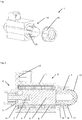
Fig. 1 : Befestigung der Magnetspule mittels einer Klemmvorrichtung -
Fig. 2 : Schnitt der Ausführung mit Klemmvorrichtung -
Fig. 3 : Befestigung der Magnetspule mittels eines Drahtbügels -
Fig. 4 : Schnitt der Ausführung mit Drahtbügel - Der Elektromagnet (1) gemäß
Fig. 1, 2 ,3 oder 4 dient zur Betätigung einer fluidischen Vorrichtung, vorzugsweise eines Ventils.
Der Elektromagnet besteht aus einer Kernbaugruppe (2) und einer auswechselbaren Magnetspule (3), wobei die Kernbaugruppe (2) aus einem Röhrchen (4), einem Magnetpol (5), einem Anker (6) und einer Ankerstange (7) besteht.
Die Magnetspule besteht aus einer Drahtwicklung (8), einem Spulenköper (9), einem Eisenrückschluss (10), einer teilweisen Kunststoffumspritzung (11) und einem daran angeformten elektrischen Steckverbinder (12).
Die Magnetspule (3) ist im zusammengebauten Zustand des Elektromagneten (1) auf dem Röhrchen (4) nach dem Spannen einer Klemmvorrichtung (15) auf der Kernbaugruppe (2) unverschieblich und drehfest in jeweils einer vorbestimmten Lage befestigt.
Nach einem Lösen der Klemmvorrichtung (15) ruht die Magnetspule (3) lose auf der Kernbaugruppe und kann ausgewechselt werden. - Die Magnetspule (3) ist im zusammengebauten Zustand des Elektromagneten (1) auf dem Röhrchen (4) nach dem Einrasten einer Verriegelung (21) auf der Kernbaugruppe (2) unverschieblich und drehfest in jeweils einer vorbestimmten Lage befestigt.
Nach einem Lösen der Verriegelung (21) ruht die Magnetspule (3) lose auf der Kernbaugruppe und kann ausgewechselt werden. - Das Röhrchen (4) ist durch ein umformendes Verfahren hergestellt, wobei das von dem Magnetpol (5) abgewandte Ende (13) des ansonsten hohlzylinderförmig geformten Röhrchens (4) als hohle Kugelkalotte geformt ist. Das Röhrchen (4) ist mit dem Magnetpol (5) fluiddicht verschweißt oder verlötet.
- In einer ersten Ausführung gemäß
Fig. 1 oder 2 ist die Magnetspule (3) in Längsrichtung gegen einen Anschlag (14) des Magnetpols (5) und hinsichtlich ihres Drehwinkels durch die Ausrichtung während des Zusammenbaus positioniert.
Sie ist durch eine Klemmvorrichtung (15) gehalten, die mindestens teilweise Teil der Kunststoffumspritzung (11) der Magnetspule (3) ist, wobei die mit einem Außengewinde versehene Klemmvorrichtung (15) durch eine Gewindemutter (16) betätigt ist, die mittels einer Konusfläche (17) mindestens zwei Laschen (18) der Klemmvorrichtung (15) gegen das Röhrchen (4) presst. - In einer zweiten Ausführung gemäß
Fig. 3 oder 4 ist die Magnetspule (3) in Längsrichtung gegen einen Anschlag (14) des Magnetpols (5) und hinsichtlich ihres Drehwinkels durch Formelemente (19, 20) des Magnetpols (5) und der Magnetspule (3), die einen Formschluss zwischen der Magnetspule (3) und dem Magnetpol (5) erzeugen, positioniert.
Die Magnetspule (3) ist auf der Kernbaugruppe (2) durch eine formschlüssig wirkende Verriegelung (21) mittels eines Verriegelungsdrahts (22) gehalten, wobei der Verriegelungsdraht (22) die Kunststoffumspritzung (11) der Magnetspule (3) mindestens einmal teilweise durchdringt und in einer Nut (23) des Magnetpols (5) so anliegt, dass die Magnetspule (3) nicht gegen die Kernbaugruppe (2) verschieblich ist, und wobei der Verriegelungsdraht (22) im Zuge des Zusammenbaus von Kernbaugruppe (2) und Magnetspule (3) so verschoben wurde, dass er in die Nut (23) eingreift. - Vorzugsweise ist bei der Ausführung gemäß
Fig. 3 oder 4 der Verriegelungsdraht (22) so geformt, dass er beweglich aber unverlierbar in Durchbrüchen und/oder Nuten der Kunststoffumspritzung (11) der Magnetspule (3) aufgenommen ist, indem mindesten ein Ende des Verriegelungsdrahts (22) um ein Hindernis (24) in der Kunststoffumspritzung (11) gebogen ist. - Ebenfalls in der Ausführung gemäß
Fig. 3 oder 4 verriegelt der Verriegelungsdraht (22) vorteilhafterweise in einer ersten, durch die Federwirkung des Verriegelungsdrahts (22) bevorzugten Lage wegen eines Eingriffs in die Nut (23) die Magnetspule (3) mit dem Magnetpol (5), und in einer zweiten durch eine äußere Druckkraft bewirkten Lage greift er nicht in die Nut (23) ein und nimmt deshalb auch nicht die Verriegelung vor. - Die Kunststoffumspritzung (11) gemäß
Fig1, 2 ,3 oder 4 weist vorzugsweise mindestens eine Öffnung auf, eine für den Magnetpol (5) und bei der Ausführung gemäßFig. 1 oder Fig. 2 eine weitere für das vom Magnetpol (5) abgewandte Ende (13) des Röhrchens (4). - Bei der Ausführung gemäß
Fig. 1 oder 2 ist die Gewindemutter (16) vorteilhafterweise aus Kunststoff hergestellt und als Hutmutter ausgeführt. - Der Elektromagnet ist vorzugsweise mittels des Magnetpols (5) mit einem fluidischen Ventil verbunden, dessen bewegliches Funktionsteil durch die Ankerstange (7) betätigt ist.
- Zum Zusammenbau des Elektromagneten (1) gemäß
Fig. 1 oder 2 wird wie folgend verfahren: - die Kernbaugruppe (2) wird an dem fluidischen Ventil befestigt,
- die mit einer Kunststoffumspritzung (11) versehene Magnetspule (3) wird über die Kernbaugruppe (2) bis zu einem Anschlag (14) geschoben,
- die Magnetspule (3) wird so verdreht, dass der an der Kunststoffumspritzung (11) angeformte elektrische Steckverbinder (12) eine vorbestimmte Richtung einnimmt,
- eine Gewindemutter (16) wird auf eine an der Kunststoffumspritzung angeformte, mit einem Außengewinde versehene Klemmvorrichtung (15) aufgeschraubt, wobei mindestens zwei Laschen (18) der Klemmvorrichtung (15) durch eine Konusfläche (17) der Gewindemutter (16) gegen ein Röhrchen (4) der Kernbaugruppe gepresst werden und dadurch die Magnetspule (3) kraftschlüssig drehfest und verschiebungsfest mit dem Röhrchen (4) verbinden.
- Zum Zusammenbau des Elektromagneten (1) gemäß
Fig. 3 oder 4 wird wie folgend verfahren: - die Kernbaugruppe (2) wird an dem fluidischen Ventil befestigt,
- die mit einer Kunststoffumspritzung (11) versehene Magnetspule (3) wird über die Kernbaugruppe (2) bis zu einem Anschlag (14) geschoben,
- die Magnetspule (3) wird so verdreht, dass ein Formelement der Magnetspule (20) in ein Formelement (19) des Magnetpols (5) eindringt, wobei der an der Kunststoffumspritzung (11) angeformte elektrische Steckverbinder (12) eine vorbestimmte Richtung einnimmt,
- die Magnetspule wird an dem Magnetpol (3) durch eine formschlüssig wirkende Verriegelung (21) mittels eines Verriegelungsdrahts (22) befestigt, indem der Verriegelungsdraht (22) so verschoben wird, dass er in eine Nut (23) in dem Magnetpol (3) eingreift, wobei der Verriegelungsdraht (22) von der die Kunststoffumspritzung (11) der Magnetspule (3) geführt wird und in der Nut (23) des Magnetpols (5) so anliegt, dass die Magnetspule (3) gegen die Kernbaugruppe (2) unverschieblich ist.
-
- 1. Elektromagnet
- 2. Kernbaugruppe
- 3. Magnetspule
- 4. Röhrchen
- 5. Magnetpol
- 6. Anker
- 7. Ankerstange
- 8. Drahtwicklung
- 9. Spulenkörper
- 10. Eisenrückschluss
- 11. Kunststoffumspritzung
- 12. Steckverbinder
- 13. Ende des Röhrchens
- 14. Anschlag
- 15. Klemmvorrichtung
- 16. Gewindemutter
- 17. Konusfläche
- 18. Lasche
- 19. Formelement
- 20. Formelement
- 21.Verriegelung
- 22. Verriegelungsdraht
- 23. Nut
- 24. Hindernis
Claims (9)
- Elektromagnet (1) zur Betätigung einer fluidischen Vorrichtung, bestehend aus einer Kernbaugruppe (2) und einer Magnetspule (3),
wobei die Kernbaugruppe (2) aus einem Röhrchen (4), einem Magnetpol (5), einem Anker (6) und einer Ankerstange (7) besteht, und wobei die Magnetspule aus einer Drahtwicklung (8), einem Spulenköper (9), einem Eisenrückschluss (10), einer mindestens teilweisen Kunststoffumspritzung (11) und einem daran angeformten elektrischen Steckverbinder (12) besteht, wobei- das Röhrchen (4) durch ein umformendes Verfahren hergestellt ist, - und das von dem Magnetpol (5) abgewandte Ende (13) des ansonsten hohlzylinderförmig geformten Röhrchens (4) als hohle Kugelkalotte geformt ist,- und das Röhrchen (4) mit dem Magnetpol (5) fluiddicht verschweißt oder verlötet ist,- und die Magnetspule (3) so ausgebildet ist, dass die Magnetspule im zusammengebauten Zustand des Elektromagneten nach dem Spannen einer Klemmvorrichtung (15) auf der Kernbaugruppe (2) unverschieblich und drehfest in jeweils einer vorbestimmten Lage befestigt ist,- und die Magnetspule (3) so ausgebildet ist, dass die Magnetspule nach einem Lösen der Klemmvorrichtung (15) lose auf der Kernbaugruppe ruht, dadurch gekennzeichnet, dass die Magnetspule (3) in Längsrichtung gegen einen Anschlag (14) des Magnetpols (5) und hinsichtlich ihres Drehwinkels durch die Ausrichtung während des Zusammenbaus positioniert ist und durch die Klemmvorrichtung (15), die mindestens teilweise Teil der Kunststoffumspritzung (11) der Magnetspule (3) ist, gehalten ist, wobei die mit einem Außengewinde versehene Klemmvorrichtung (15) durch eine Gewindemutter (16) gespannt ist, die mittels einer Konusfläche (17) mindestens zwei Laschen (18) der Klemmvorrichtung (15) gegen das Röhrchen (4) presst. - Elektromagnet (1) zur Betätigung einer fluidischen Vorrichtung, bestehend aus einer Kernbaugruppe (2) und einer Magnetspule (3),
Thomas Magnete GmbH, P-16-40-WO-EP_Korrektur in A9_Rein_R. 71 (3) EPÜ 3555896 wobei die Kernbaugruppe (2) aus einem Röhrchen (4), einem Magnetpol (5), einem Anker (6) und einer Ankerstange (7) besteht, und wobei die Magnetspule aus einer Drahtwicklung (8), einem Spulenköper (9), einem Eisenrückschluss (10), einer mindestens teilweisen Kunststoffumspritzung (11) und einem daran angeformten elektrischen Steckverbinder (12) besteht, wobei- das Röhrchen (4) durch ein umformendes Verfahren hergestellt ist, - und das von dem Magnetpol (5) abgewandte Ende (13) des ansonsten hohlzylinderförmig geformten Röhrchens (4) als hohle Kugelkalotte geformt ist,- und das Röhrchen (4) mit dem Magnetpol (5) fluiddicht verschweißt oder verlötet ist,- und die Magnetspule (3) so ausgebildet ist, dass die Magnetspule im zusammengebauten Zustand des Elektromagneten nach dem Einrasten einer Verriegelung (21) auf der Kernbaugruppe (2) unverschieblich und drehfest in jeweils einer vorbestimmten Lage befestigt ist,- und die Magnetspule (3) so ausgebildet ist, dass die Magnetspule nach einem Lösen der Verriegelung (21) lose auf der Kernbaugruppe ruht, dadurch gekennzeichnet, dass die Magnetspule (3) in Längsrichtung gegen einen Anschlag (14) des Magnetpols (5) und hinsichtlich ihres Drehwinkels durch Formelemente (19, 20) des Magnetpols (5) und der Magnetspule (3), die einen Formschluss zwischen der Magnetspule (3) und dem Magnetpol (5) erzeugen, positioniert ist und durch die Verriegelung (21), welche eine formschlüssig wirkende Verriegelung (21) darstellt, mittels eines Verriegelungsdrahts (22) gehalten ist, wobei der Verriegelungsdraht (22) die Kunststoffumspritzung (11) der Magnetspule (3) mindestens einmal teilweise durchdringt und in einer Nut (23) des Magnetpols (5) so anliegt, dass die Magnetspule (3) gegen die Kernbaugruppe (2) unverschieblich ist, und wobei der Verriegelungsdraht (22) im Zuge des Zusammenbaus von Kernbaugruppe (2) und Magnetspule (3) so verschoben wurde, dass er in die Nut (23) eingreift. - Elektromagnet nach Anspruch 2, wobei der Verriegelungsdraht (22) so geformt ist, dass er beweglich aber unverlierbar in Durchbrüchen und/oder Thomas Magnete GmbH, P-16-40-WO-EP_Korrektur in A9_Rein_R. 71 (3) EPÜ Nuten der Kunststoffumspritzung (11) der Magnetspule (3) aufgenommen ist, indem mindesten ein Ende des Verriegelungsdrahts (22) um ein Hindernis (24) in der Kunststoffumspritzung (11) gebogen ist.
- Elektromagnet nach einem der Ansprüche 2 oder 3, wobei der Verriegelungsdraht (22) in einer ersten, durch die Federwirkung des Verriegelungsdrahts (22) bevorzugten Lage wegen eines Eingriffs in die Nut (23) die Magnetspule (3) mit dem Magnetpol (5) verriegelt,
und in einer zweiten durch eine äußere Druckkraft bewirkten Lage die Verriegelung freigibt. - Elektromagnet nach Anspruch 1, wobei die Kunststoffumspritzung (11) mindestens zwei Öffnungen aufweist, eine für den Magnetpol (5) und eine für das vom Magnetpol (5) abgewandte Ende (13) des Röhrchens (4).
- Elektromagnet nach Anspruch 1 oder 5, wobei die Gewindemutter (16) aus Kunststoff hergestellt ist und/oder als Hutmutter ausgeführt ist.
- Elektromagnet nach einem der vorhergehenden Ansprüche, wobei der Elektromagnet mittels des Magnetpols (5) mit einem fluidischen Ventil verbunden ist, dessen bewegliches Funktionsteil durch die Ankerstange (7) betätigt ist.
- Verfahren zum Zusammenbau eines Elektromagneten (1), der aus einer Kernbaugruppe (2) und einer Magnetspule (3) besteht, wobei- die Kernbaugruppe (2) an einem fluidischen Ventil befestigt wird,- die mit einer Kunststoffumspritzung (11) versehene Magnetspule (3) über die Kernbaugruppe (2) bis zu einem Anschlag (14) geschoben wird,- die Magnetspule (3) so verdreht wird, dass der an der Kunststoffumspritzung (11) angeformte elektrische Steckverbinder (12) eine vorbestimmte Richtung einnimmt,- eine Gewindemutter (16) auf eine an der Kunststoffumspritzung angeformte, mit einem Außengewinde versehene Klemmvorrichtung (15) aufgeschraubt wird, wobei mindestens zwei Laschen (18) der Klemmvorrichtung (15) durch eine Konusfläche (17) der Gewindemutter (16) gegen ein Röhrchen (4) der Kernbaugruppe gepresst werden und dadurch die Magnetspule (3) kraftschlüssig drehfest und verschiebungsfest mit dem Röhrchen (4) verbinden.
- Verfahren zum Zusammenbau eines Elektromagneten (1), der aus einer Kernbaugruppe (2) und einer Magnetspule (3) besteht, wobei die Kernbaugruppe aus einem Magnetpol (5), einem Röhrchen (4), einem Anker (6) und einer Ankerstange (7) besteht, wobei- die Kernbaugruppe (2) an einem fluidischen Ventil befestigt wird,- die mit einer Kunststoffumspritzung (11) versehene Magnetspule (3) über die Kernbaugruppe (2) bis zu einem Anschlag (14) geschoben wird,- die Magnetspule (3) so verdreht wird, dass ein Formelement (20) der Magnetspule (3) in ein Formelement (19) des Magnetpols (5) eindringt, wobei der an der Kunststoffumspritzung (11) angeformte elektrische Steckverbinder (12) eine vorbestimmte Richtung einnimmt,- die Magnetspule (3) an dem Magnetpol (5) durch eine formschlüssig wirkende Verriegelung (21) mittels eines Verriegelungsdrahts (22) befestigt wird, indem der Verriegelungsdraht (22) so verschoben wird, dass er in eine Nut (23) in dem Magnetpol (5) eingreift, wobei der Verriegelungsdraht (22) von der Kunststoffumspritzung (11) der Magnetspule (3) geführt wird und in der Nut (23) des Magnetpols (5) so anliegt, dass die Magnetspule (3) gegen die Kernbaugruppe (2) unverschieblich ist.
Applications Claiming Priority (2)
| Application Number | Priority Date | Filing Date | Title |
|---|---|---|---|
| DE102016014755.5A DE102016014755B4 (de) | 2016-12-13 | 2016-12-13 | Elektromagnet mit auswechselbarer Magnetspule und Verfahren zum Zusammenbau des Elektromagneten |
| PCT/EP2017/001410 WO2018108312A1 (de) | 2016-12-13 | 2017-12-06 | Elektromagnet mit auswechselbarer magnetspule und verfahren zum zusammenbau des elektromagneten |
Publications (2)
| Publication Number | Publication Date |
|---|---|
| EP3555896A1 EP3555896A1 (de) | 2019-10-23 |
| EP3555896B1 true EP3555896B1 (de) | 2021-03-31 |
Family
ID=61189395
Family Applications (1)
| Application Number | Title | Priority Date | Filing Date |
|---|---|---|---|
| EP17840530.4A Active EP3555896B1 (de) | 2016-12-13 | 2017-12-06 | Elektromagnet mit auswechselbarer magnetspule und verfahren zum zusammenbau des elektromagneten |
Country Status (3)
| Country | Link |
|---|---|
| EP (1) | EP3555896B1 (de) |
| DE (1) | DE102016014755B4 (de) |
| WO (1) | WO2018108312A1 (de) |
Families Citing this family (2)
| Publication number | Priority date | Publication date | Assignee | Title |
|---|---|---|---|---|
| DE102018117172A1 (de) * | 2018-07-16 | 2020-01-16 | Svm Schultz Verwaltungs-Gmbh & Co. Kg | Spulenkörperanordnung |
| DE102018219428A1 (de) * | 2018-11-14 | 2020-05-14 | Robert Bosch Gmbh | Elektromagnetisch betätigbares hydraulisches Einbauventil |
Family Cites Families (8)
| Publication number | Priority date | Publication date | Assignee | Title |
|---|---|---|---|---|
| JP3069742B2 (ja) * | 1990-10-11 | 2000-07-24 | 日清紡績株式会社 | 電磁弁装置 |
| DE4142004A1 (de) * | 1991-12-19 | 1993-06-24 | Bosch Gmbh Robert | Hydraulische bremsanlage, insbesondere fuer kraftfahrzeuge |
| JP3311427B2 (ja) * | 1993-06-18 | 2002-08-05 | 株式会社デンソー | 複合磁性部材およびその製法およびこの複合磁性部材を用いた電磁弁 |
| US5944262A (en) * | 1997-02-14 | 1999-08-31 | Denso Corporation | Fuel injection valve and its manufacturing method |
| US6486761B1 (en) * | 1998-09-10 | 2002-11-26 | Continental Teves Ag & Co. Ohg | Electromagnetic valve |
| KR100653406B1 (ko) * | 2003-11-12 | 2006-12-04 | 주식회사 만도 | 전자제어식 브레이크 시스템용 솔레노이드밸브의코일조립체 고정장치 |
| JP5453442B2 (ja) * | 2008-10-31 | 2014-03-26 | ローベルト ボツシユ ゲゼルシヤフト ミツト ベシユレンクテル ハフツング | 電磁石 |
| DE102009050564B4 (de) * | 2009-10-23 | 2022-10-13 | Svm Magnet Schultz Verwaltungs-Gmbh & Co. Kg | Befestigung für Elektromagneten |
-
2016
- 2016-12-13 DE DE102016014755.5A patent/DE102016014755B4/de active Active
-
2017
- 2017-12-06 EP EP17840530.4A patent/EP3555896B1/de active Active
- 2017-12-06 WO PCT/EP2017/001410 patent/WO2018108312A1/de not_active Ceased
Non-Patent Citations (1)
| Title |
|---|
| None * |
Also Published As
| Publication number | Publication date |
|---|---|
| WO2018108312A1 (de) | 2018-06-21 |
| DE102016014755B4 (de) | 2023-10-12 |
| WO2018108312A4 (de) | 2018-08-16 |
| DE102016014755A1 (de) | 2018-06-14 |
| EP3555896A1 (de) | 2019-10-23 |
Similar Documents
| Publication | Publication Date | Title |
|---|---|---|
| EP2240943A2 (de) | Betätigungsmagnet | |
| EP2568204B1 (de) | Magnetventil und Verfahren zur Steuerung des Magnetventils | |
| EP1144812A1 (de) | Elektromagnetischer aktuator | |
| EP2041762B1 (de) | Vorrichtung zum überwachen des zustandes einer schutzeinrichtung einer maschine | |
| EP2669557A2 (de) | Rastvorrichtung für ein Schieberventil | |
| WO2017084662A1 (de) | Elektromagnetische stellvorrichtung | |
| DE4037172C2 (de) | Magnetventil | |
| WO2021052560A1 (de) | Elektromagnetventil für ein kraftfahrzeug und verfahren zur herstellung einer bewegungseinheit aus einem anker und einer ventileinheit für ein derartiges elektromagnetventil | |
| DE102016014755B4 (de) | Elektromagnet mit auswechselbarer Magnetspule und Verfahren zum Zusammenbau des Elektromagneten | |
| WO2008040618A1 (de) | Druckregelventil | |
| EP3141737B1 (de) | Ventil zum zumessen eines fluids | |
| DE19729935B4 (de) | Hydraulisches Einbauventil, insbesondere für eine hydraulische Nockenwellenverstellung an einem Kraftfahrzeugmotor | |
| DE102018200084B4 (de) | Verfahren zur Herstellung einer elektromagnetischen Ventilanordnung sowie elektromagnetische Ventilanordnung | |
| DE102004017089B4 (de) | Betätigungsvorrichtung, insbesondere Proportional-Doppelhubmagnet | |
| DE29903873U1 (de) | Elektrisches Gerät, insbesondere Hubmagnet | |
| EP4194720A1 (de) | Verriegelungseinheit | |
| DE102010027736A1 (de) | Stellungsregler, insbesondere für ein durch einen Antrieb betätigbares Ventil, sowie Klemme für einen derartigen Stellungsregler | |
| DE102008008735B4 (de) | Elektromagnetischer Antrieb | |
| EP3159535A1 (de) | Elektromagnetisches ventil | |
| DE69517308T2 (de) | Magnetischer betätiger mit mehrfach luftspalten | |
| EP1981746A1 (de) | Hydraulikaggregat | |
| DE102006028437B4 (de) | Formschlüssige Magnetkernsicherung | |
| EP1975487A2 (de) | Druckrohr für ein Wegemesssystem | |
| DE102018118668A1 (de) | Elektromagnetisches Druckregelventil | |
| DE20218782U1 (de) | Elektromagnetische Stellvorrichtung |
Legal Events
| Date | Code | Title | Description |
|---|---|---|---|
| STAA | Information on the status of an ep patent application or granted ep patent |
Free format text: STATUS: UNKNOWN |
|
| STAA | Information on the status of an ep patent application or granted ep patent |
Free format text: STATUS: THE INTERNATIONAL PUBLICATION HAS BEEN MADE |
|
| PUAI | Public reference made under article 153(3) epc to a published international application that has entered the european phase |
Free format text: ORIGINAL CODE: 0009012 |
|
| STAA | Information on the status of an ep patent application or granted ep patent |
Free format text: STATUS: REQUEST FOR EXAMINATION WAS MADE |
|
| 17P | Request for examination filed |
Effective date: 20190514 |
|
| AK | Designated contracting states |
Kind code of ref document: A1 Designated state(s): AL AT BE BG CH CY CZ DE DK EE ES FI FR GB GR HR HU IE IS IT LI LT LU LV MC MK MT NL NO PL PT RO RS SE SI SK SM TR |
|
| AX | Request for extension of the european patent |
Extension state: BA ME |
|
| DAV | Request for validation of the european patent (deleted) | ||
| DAX | Request for extension of the european patent (deleted) | ||
| STAA | Information on the status of an ep patent application or granted ep patent |
Free format text: STATUS: EXAMINATION IS IN PROGRESS |
|
| 17Q | First examination report despatched |
Effective date: 20200520 |
|
| GRAP | Despatch of communication of intention to grant a patent |
Free format text: ORIGINAL CODE: EPIDOSNIGR1 |
|
| STAA | Information on the status of an ep patent application or granted ep patent |
Free format text: STATUS: GRANT OF PATENT IS INTENDED |
|
| INTG | Intention to grant announced |
Effective date: 20200915 |
|
| GRAJ | Information related to disapproval of communication of intention to grant by the applicant or resumption of examination proceedings by the epo deleted |
Free format text: ORIGINAL CODE: EPIDOSDIGR1 |
|
| STAA | Information on the status of an ep patent application or granted ep patent |
Free format text: STATUS: EXAMINATION IS IN PROGRESS |
|
| INTC | Intention to grant announced (deleted) | ||
| GRAS | Grant fee paid |
Free format text: ORIGINAL CODE: EPIDOSNIGR3 |
|
| STAA | Information on the status of an ep patent application or granted ep patent |
Free format text: STATUS: GRANT OF PATENT IS INTENDED |
|
| GRAP | Despatch of communication of intention to grant a patent |
Free format text: ORIGINAL CODE: EPIDOSNIGR1 |
|
| INTG | Intention to grant announced |
Effective date: 20201221 |
|
| GRAA | (expected) grant |
Free format text: ORIGINAL CODE: 0009210 |
|
| STAA | Information on the status of an ep patent application or granted ep patent |
Free format text: STATUS: THE PATENT HAS BEEN GRANTED |
|
| AK | Designated contracting states |
Kind code of ref document: B1 Designated state(s): AL AT BE BG CH CY CZ DE DK EE ES FI FR GB GR HR HU IE IS IT LI LT LU LV MC MK MT NL NO PL PT RO RS SE SI SK SM TR |
|
| REG | Reference to a national code |
Ref country code: GB Ref legal event code: FG4D Free format text: NOT ENGLISH Ref country code: CH Ref legal event code: EP |
|
| REG | Reference to a national code |
Ref country code: AT Ref legal event code: REF Ref document number: 1377867 Country of ref document: AT Kind code of ref document: T Effective date: 20210415 |
|
| REG | Reference to a national code |
Ref country code: DE Ref legal event code: R096 Ref document number: 502017009938 Country of ref document: DE |
|
| REG | Reference to a national code |
Ref country code: IE Ref legal event code: FG4D Free format text: LANGUAGE OF EP DOCUMENT: GERMAN |
|
| REG | Reference to a national code |
Ref country code: LT Ref legal event code: MG9D |
|
| PG25 | Lapsed in a contracting state [announced via postgrant information from national office to epo] |
Ref country code: NO Free format text: LAPSE BECAUSE OF FAILURE TO SUBMIT A TRANSLATION OF THE DESCRIPTION OR TO PAY THE FEE WITHIN THE PRESCRIBED TIME-LIMIT Effective date: 20210630 Ref country code: HR Free format text: LAPSE BECAUSE OF FAILURE TO SUBMIT A TRANSLATION OF THE DESCRIPTION OR TO PAY THE FEE WITHIN THE PRESCRIBED TIME-LIMIT Effective date: 20210331 Ref country code: FI Free format text: LAPSE BECAUSE OF FAILURE TO SUBMIT A TRANSLATION OF THE DESCRIPTION OR TO PAY THE FEE WITHIN THE PRESCRIBED TIME-LIMIT Effective date: 20210331 Ref country code: BG Free format text: LAPSE BECAUSE OF FAILURE TO SUBMIT A TRANSLATION OF THE DESCRIPTION OR TO PAY THE FEE WITHIN THE PRESCRIBED TIME-LIMIT Effective date: 20210630 |
|
| PG25 | Lapsed in a contracting state [announced via postgrant information from national office to epo] |
Ref country code: SE Free format text: LAPSE BECAUSE OF FAILURE TO SUBMIT A TRANSLATION OF THE DESCRIPTION OR TO PAY THE FEE WITHIN THE PRESCRIBED TIME-LIMIT Effective date: 20210331 Ref country code: LV Free format text: LAPSE BECAUSE OF FAILURE TO SUBMIT A TRANSLATION OF THE DESCRIPTION OR TO PAY THE FEE WITHIN THE PRESCRIBED TIME-LIMIT Effective date: 20210331 Ref country code: RS Free format text: LAPSE BECAUSE OF FAILURE TO SUBMIT A TRANSLATION OF THE DESCRIPTION OR TO PAY THE FEE WITHIN THE PRESCRIBED TIME-LIMIT Effective date: 20210331 |
|
| REG | Reference to a national code |
Ref country code: NL Ref legal event code: MP Effective date: 20210331 |
|
| PG25 | Lapsed in a contracting state [announced via postgrant information from national office to epo] |
Ref country code: SM Free format text: LAPSE BECAUSE OF FAILURE TO SUBMIT A TRANSLATION OF THE DESCRIPTION OR TO PAY THE FEE WITHIN THE PRESCRIBED TIME-LIMIT Effective date: 20210331 Ref country code: NL Free format text: LAPSE BECAUSE OF FAILURE TO SUBMIT A TRANSLATION OF THE DESCRIPTION OR TO PAY THE FEE WITHIN THE PRESCRIBED TIME-LIMIT Effective date: 20210331 Ref country code: LT Free format text: LAPSE BECAUSE OF FAILURE TO SUBMIT A TRANSLATION OF THE DESCRIPTION OR TO PAY THE FEE WITHIN THE PRESCRIBED TIME-LIMIT Effective date: 20210331 Ref country code: CZ Free format text: LAPSE BECAUSE OF FAILURE TO SUBMIT A TRANSLATION OF THE DESCRIPTION OR TO PAY THE FEE WITHIN THE PRESCRIBED TIME-LIMIT Effective date: 20210331 Ref country code: EE Free format text: LAPSE BECAUSE OF FAILURE TO SUBMIT A TRANSLATION OF THE DESCRIPTION OR TO PAY THE FEE WITHIN THE PRESCRIBED TIME-LIMIT Effective date: 20210331 |
|
| PG25 | Lapsed in a contracting state [announced via postgrant information from national office to epo] |
Ref country code: IS Free format text: LAPSE BECAUSE OF FAILURE TO SUBMIT A TRANSLATION OF THE DESCRIPTION OR TO PAY THE FEE WITHIN THE PRESCRIBED TIME-LIMIT Effective date: 20210731 Ref country code: SK Free format text: LAPSE BECAUSE OF FAILURE TO SUBMIT A TRANSLATION OF THE DESCRIPTION OR TO PAY THE FEE WITHIN THE PRESCRIBED TIME-LIMIT Effective date: 20210331 Ref country code: RO Free format text: LAPSE BECAUSE OF FAILURE TO SUBMIT A TRANSLATION OF THE DESCRIPTION OR TO PAY THE FEE WITHIN THE PRESCRIBED TIME-LIMIT Effective date: 20210331 Ref country code: PL Free format text: LAPSE BECAUSE OF FAILURE TO SUBMIT A TRANSLATION OF THE DESCRIPTION OR TO PAY THE FEE WITHIN THE PRESCRIBED TIME-LIMIT Effective date: 20210331 Ref country code: PT Free format text: LAPSE BECAUSE OF FAILURE TO SUBMIT A TRANSLATION OF THE DESCRIPTION OR TO PAY THE FEE WITHIN THE PRESCRIBED TIME-LIMIT Effective date: 20210802 |
|
| REG | Reference to a national code |
Ref country code: DE Ref legal event code: R097 Ref document number: 502017009938 Country of ref document: DE |
|
| PG25 | Lapsed in a contracting state [announced via postgrant information from national office to epo] |
Ref country code: ES Free format text: LAPSE BECAUSE OF FAILURE TO SUBMIT A TRANSLATION OF THE DESCRIPTION OR TO PAY THE FEE WITHIN THE PRESCRIBED TIME-LIMIT Effective date: 20210331 Ref country code: AL Free format text: LAPSE BECAUSE OF FAILURE TO SUBMIT A TRANSLATION OF THE DESCRIPTION OR TO PAY THE FEE WITHIN THE PRESCRIBED TIME-LIMIT Effective date: 20210331 Ref country code: DK Free format text: LAPSE BECAUSE OF FAILURE TO SUBMIT A TRANSLATION OF THE DESCRIPTION OR TO PAY THE FEE WITHIN THE PRESCRIBED TIME-LIMIT Effective date: 20210331 |
|
| PLBE | No opposition filed within time limit |
Free format text: ORIGINAL CODE: 0009261 |
|
| STAA | Information on the status of an ep patent application or granted ep patent |
Free format text: STATUS: NO OPPOSITION FILED WITHIN TIME LIMIT |
|
| 26N | No opposition filed |
Effective date: 20220104 |
|
| PG25 | Lapsed in a contracting state [announced via postgrant information from national office to epo] |
Ref country code: IS Free format text: LAPSE BECAUSE OF FAILURE TO SUBMIT A TRANSLATION OF THE DESCRIPTION OR TO PAY THE FEE WITHIN THE PRESCRIBED TIME-LIMIT Effective date: 20210731 |
|
| PG25 | Lapsed in a contracting state [announced via postgrant information from national office to epo] |
Ref country code: MC Free format text: LAPSE BECAUSE OF FAILURE TO SUBMIT A TRANSLATION OF THE DESCRIPTION OR TO PAY THE FEE WITHIN THE PRESCRIBED TIME-LIMIT Effective date: 20210331 |
|
| REG | Reference to a national code |
Ref country code: CH Ref legal event code: PL |
|
| GBPC | Gb: european patent ceased through non-payment of renewal fee |
Effective date: 20211206 |
|
| REG | Reference to a national code |
Ref country code: BE Ref legal event code: MM Effective date: 20211231 |
|
| PG25 | Lapsed in a contracting state [announced via postgrant information from national office to epo] |
Ref country code: LU Free format text: LAPSE BECAUSE OF NON-PAYMENT OF DUE FEES Effective date: 20211206 Ref country code: IE Free format text: LAPSE BECAUSE OF NON-PAYMENT OF DUE FEES Effective date: 20211206 Ref country code: GB Free format text: LAPSE BECAUSE OF NON-PAYMENT OF DUE FEES Effective date: 20211206 |
|
| PG25 | Lapsed in a contracting state [announced via postgrant information from national office to epo] |
Ref country code: BE Free format text: LAPSE BECAUSE OF NON-PAYMENT OF DUE FEES Effective date: 20211231 |
|
| PG25 | Lapsed in a contracting state [announced via postgrant information from national office to epo] |
Ref country code: LI Free format text: LAPSE BECAUSE OF NON-PAYMENT OF DUE FEES Effective date: 20211231 Ref country code: CH Free format text: LAPSE BECAUSE OF NON-PAYMENT OF DUE FEES Effective date: 20211231 |
|
| PG25 | Lapsed in a contracting state [announced via postgrant information from national office to epo] |
Ref country code: CY Free format text: LAPSE BECAUSE OF FAILURE TO SUBMIT A TRANSLATION OF THE DESCRIPTION OR TO PAY THE FEE WITHIN THE PRESCRIBED TIME-LIMIT Effective date: 20210331 |
|
| PG25 | Lapsed in a contracting state [announced via postgrant information from national office to epo] |
Ref country code: HU Free format text: LAPSE BECAUSE OF FAILURE TO SUBMIT A TRANSLATION OF THE DESCRIPTION OR TO PAY THE FEE WITHIN THE PRESCRIBED TIME-LIMIT; INVALID AB INITIO Effective date: 20171206 Ref country code: GR Free format text: LAPSE BECAUSE OF FAILURE TO SUBMIT A TRANSLATION OF THE DESCRIPTION OR TO PAY THE FEE WITHIN THE PRESCRIBED TIME-LIMIT Effective date: 20210331 |
|
| PGFP | Annual fee paid to national office [announced via postgrant information from national office to epo] |
Ref country code: DE Payment date: 20231231 Year of fee payment: 7 |
|
| REG | Reference to a national code |
Ref country code: AT Ref legal event code: MM01 Ref document number: 1377867 Country of ref document: AT Kind code of ref document: T Effective date: 20221206 |
|
| PG25 | Lapsed in a contracting state [announced via postgrant information from national office to epo] |
Ref country code: AT Free format text: LAPSE BECAUSE OF NON-PAYMENT OF DUE FEES Effective date: 20221206 |
|
| PG25 | Lapsed in a contracting state [announced via postgrant information from national office to epo] |
Ref country code: MK Free format text: LAPSE BECAUSE OF FAILURE TO SUBMIT A TRANSLATION OF THE DESCRIPTION OR TO PAY THE FEE WITHIN THE PRESCRIBED TIME-LIMIT Effective date: 20210331 Ref country code: AT Free format text: LAPSE BECAUSE OF NON-PAYMENT OF DUE FEES Effective date: 20221206 |
|
| PG25 | Lapsed in a contracting state [announced via postgrant information from national office to epo] |
Ref country code: MT Free format text: LAPSE BECAUSE OF FAILURE TO SUBMIT A TRANSLATION OF THE DESCRIPTION OR TO PAY THE FEE WITHIN THE PRESCRIBED TIME-LIMIT Effective date: 20210331 |
|
| PGFP | Annual fee paid to national office [announced via postgrant information from national office to epo] |
Ref country code: FR Payment date: 20241219 Year of fee payment: 8 |
|
| PGFP | Annual fee paid to national office [announced via postgrant information from national office to epo] |
Ref country code: IT Payment date: 20241216 Year of fee payment: 8 |
|
| REG | Reference to a national code |
Ref country code: DE Ref legal event code: R119 Ref document number: 502017009938 Country of ref document: DE |
|
| PG25 | Lapsed in a contracting state [announced via postgrant information from national office to epo] |
Ref country code: DE Free format text: LAPSE BECAUSE OF NON-PAYMENT OF DUE FEES Effective date: 20250701 |
|
| PG25 | Lapsed in a contracting state [announced via postgrant information from national office to epo] |
Ref country code: TR Free format text: LAPSE BECAUSE OF FAILURE TO SUBMIT A TRANSLATION OF THE DESCRIPTION OR TO PAY THE FEE WITHIN THE PRESCRIBED TIME-LIMIT Effective date: 20210331 |
|
| PGFP | Annual fee paid to national office [announced via postgrant information from national office to epo] |
Ref country code: AT Payment date: 20260410 Year of fee payment: 5 |