EP3555871B1 - Unité de commande anti-incendie - Google Patents
Unité de commande anti-incendie Download PDFInfo
- Publication number
- EP3555871B1 EP3555871B1 EP17829701.6A EP17829701A EP3555871B1 EP 3555871 B1 EP3555871 B1 EP 3555871B1 EP 17829701 A EP17829701 A EP 17829701A EP 3555871 B1 EP3555871 B1 EP 3555871B1
- Authority
- EP
- European Patent Office
- Prior art keywords
- board
- control unit
- fire
- boards
- communication
- Prior art date
- Legal status (The legal status is an assumption and is not a legal conclusion. Google has not performed a legal analysis and makes no representation as to the accuracy of the status listed.)
- Active
Links
- 238000004891 communication Methods 0.000 claims description 70
- 238000012545 processing Methods 0.000 claims description 62
- 239000013598 vector Substances 0.000 claims description 14
- 238000000034 method Methods 0.000 claims description 12
- 230000008569 process Effects 0.000 claims description 8
- 230000006870 function Effects 0.000 description 13
- 238000010586 diagram Methods 0.000 description 10
- 230000009977 dual effect Effects 0.000 description 10
- 230000007257 malfunction Effects 0.000 description 10
- 230000000903 blocking effect Effects 0.000 description 9
- 230000005540 biological transmission Effects 0.000 description 8
- 238000001514 detection method Methods 0.000 description 7
- 230000000875 corresponding effect Effects 0.000 description 4
- 238000013480 data collection Methods 0.000 description 4
- 238000013507 mapping Methods 0.000 description 4
- 238000009434 installation Methods 0.000 description 3
- 238000012423 maintenance Methods 0.000 description 3
- 238000012544 monitoring process Methods 0.000 description 3
- 230000004913 activation Effects 0.000 description 2
- 230000006399 behavior Effects 0.000 description 2
- 230000001276 controlling effect Effects 0.000 description 2
- 238000003780 insertion Methods 0.000 description 2
- 230000037431 insertion Effects 0.000 description 2
- 238000004519 manufacturing process Methods 0.000 description 2
- 230000001737 promoting effect Effects 0.000 description 2
- 230000008521 reorganization Effects 0.000 description 2
- 238000004092 self-diagnosis Methods 0.000 description 2
- 238000010521 absorption reaction Methods 0.000 description 1
- XAGFODPZIPBFFR-UHFFFAOYSA-N aluminium Chemical compound [Al] XAGFODPZIPBFFR-UHFFFAOYSA-N 0.000 description 1
- 229910052782 aluminium Inorganic materials 0.000 description 1
- 238000013459 approach Methods 0.000 description 1
- 230000015572 biosynthetic process Effects 0.000 description 1
- 238000004364 calculation method Methods 0.000 description 1
- 238000006243 chemical reaction Methods 0.000 description 1
- 230000000052 comparative effect Effects 0.000 description 1
- 230000001010 compromised effect Effects 0.000 description 1
- 239000004020 conductor Substances 0.000 description 1
- 238000010276 construction Methods 0.000 description 1
- 230000002596 correlated effect Effects 0.000 description 1
- 238000011161 development Methods 0.000 description 1
- 238000011156 evaluation Methods 0.000 description 1
- 239000003063 flame retardant Substances 0.000 description 1
- 231100001261 hazardous Toxicity 0.000 description 1
- 230000008676 import Effects 0.000 description 1
- 238000009413 insulation Methods 0.000 description 1
- 230000010354 integration Effects 0.000 description 1
- 230000007246 mechanism Effects 0.000 description 1
- 230000002093 peripheral effect Effects 0.000 description 1
- 230000001360 synchronised effect Effects 0.000 description 1
- 230000002195 synergetic effect Effects 0.000 description 1
- 238000003786 synthesis reaction Methods 0.000 description 1
Images


Classifications
-
- G—PHYSICS
- G08—SIGNALLING
- G08B—SIGNALLING OR CALLING SYSTEMS; ORDER TELEGRAPHS; ALARM SYSTEMS
- G08B29/00—Checking or monitoring of signalling or alarm systems; Prevention or correction of operating errors, e.g. preventing unauthorised operation
- G08B29/16—Security signalling or alarm systems, e.g. redundant systems
-
- G—PHYSICS
- G06—COMPUTING; CALCULATING OR COUNTING
- G06F—ELECTRIC DIGITAL DATA PROCESSING
- G06F11/00—Error detection; Error correction; Monitoring
- G06F11/07—Responding to the occurrence of a fault, e.g. fault tolerance
- G06F11/16—Error detection or correction of the data by redundancy in hardware
- G06F11/1629—Error detection by comparing the output of redundant processing systems
- G06F11/1633—Error detection by comparing the output of redundant processing systems using mutual exchange of the output between the redundant processing components
-
- G—PHYSICS
- G06—COMPUTING; CALCULATING OR COUNTING
- G06F—ELECTRIC DIGITAL DATA PROCESSING
- G06F11/00—Error detection; Error correction; Monitoring
- G06F11/07—Responding to the occurrence of a fault, e.g. fault tolerance
- G06F11/16—Error detection or correction of the data by redundancy in hardware
- G06F11/1629—Error detection by comparing the output of redundant processing systems
- G06F11/165—Error detection by comparing the output of redundant processing systems with continued operation after detection of the error
-
- G—PHYSICS
- G06—COMPUTING; CALCULATING OR COUNTING
- G06F—ELECTRIC DIGITAL DATA PROCESSING
- G06F11/00—Error detection; Error correction; Monitoring
- G06F11/30—Monitoring
- G06F11/3003—Monitoring arrangements specially adapted to the computing system or computing system component being monitored
- G06F11/3013—Monitoring arrangements specially adapted to the computing system or computing system component being monitored where the computing system is an embedded system, i.e. a combination of hardware and software dedicated to perform a certain function in mobile devices, printers, automotive or aircraft systems
-
- G—PHYSICS
- G06—COMPUTING; CALCULATING OR COUNTING
- G06F—ELECTRIC DIGITAL DATA PROCESSING
- G06F11/00—Error detection; Error correction; Monitoring
- G06F11/30—Monitoring
- G06F11/3055—Monitoring arrangements for monitoring the status of the computing system or of the computing system component, e.g. monitoring if the computing system is on, off, available, not available
-
- G—PHYSICS
- G06—COMPUTING; CALCULATING OR COUNTING
- G06F—ELECTRIC DIGITAL DATA PROCESSING
- G06F11/00—Error detection; Error correction; Monitoring
- G06F11/30—Monitoring
- G06F11/3058—Monitoring arrangements for monitoring environmental properties or parameters of the computing system or of the computing system component, e.g. monitoring of power, currents, temperature, humidity, position, vibrations
-
- G—PHYSICS
- G08—SIGNALLING
- G08B—SIGNALLING OR CALLING SYSTEMS; ORDER TELEGRAPHS; ALARM SYSTEMS
- G08B25/00—Alarm systems in which the location of the alarm condition is signalled to a central station, e.g. fire or police telegraphic systems
- G08B25/14—Central alarm receiver or annunciator arrangements
-
- H—ELECTRICITY
- H04—ELECTRIC COMMUNICATION TECHNIQUE
- H04L—TRANSMISSION OF DIGITAL INFORMATION, e.g. TELEGRAPHIC COMMUNICATION
- H04L12/00—Data switching networks
- H04L12/28—Data switching networks characterised by path configuration, e.g. LAN [Local Area Networks] or WAN [Wide Area Networks]
- H04L12/40—Bus networks
-
- G—PHYSICS
- G06—COMPUTING; CALCULATING OR COUNTING
- G06F—ELECTRIC DIGITAL DATA PROCESSING
- G06F11/00—Error detection; Error correction; Monitoring
- G06F11/07—Responding to the occurrence of a fault, e.g. fault tolerance
- G06F11/0703—Error or fault processing not based on redundancy, i.e. by taking additional measures to deal with the error or fault not making use of redundancy in operation, in hardware, or in data representation
- G06F11/0751—Error or fault detection not based on redundancy
-
- G—PHYSICS
- G06—COMPUTING; CALCULATING OR COUNTING
- G06F—ELECTRIC DIGITAL DATA PROCESSING
- G06F11/00—Error detection; Error correction; Monitoring
- G06F11/07—Responding to the occurrence of a fault, e.g. fault tolerance
- G06F11/16—Error detection or correction of the data by redundancy in hardware
- G06F11/20—Error detection or correction of the data by redundancy in hardware using active fault-masking, e.g. by switching out faulty elements or by switching in spare elements
- G06F11/202—Error detection or correction of the data by redundancy in hardware using active fault-masking, e.g. by switching out faulty elements or by switching in spare elements where processing functionality is redundant
- G06F11/2023—Failover techniques
Definitions
- the present invention relates to a fire-prevention control unit comprising several circuit boards and a dedicated communication bus for communication between the circuit boards.
- the circuit boards comprise at least one processing board, at least one input board and at least one output board, so that the processing board is intended to process input data received from the input board according to a programmable computational array and to generate commands to send to the output board.
- the input board and the output board are intended to communicate with one or more devices to be monitored and/or controlled.
- control units are intended to identify and report a malfunction of one or more devices, monitored by the same control unit, for example caused by an outbreak of fire or by a gas leak.
- control units generally have sensors that monitor the operation of one or more devices, said sensors communicating with one or more input boards that transmit data to a processing board.
- the processing board processes the data so as to assess whether there is a malfunction of the devices monitored and generate command signals that it transmits to the output boards, which in turn can command block of the devices monitored and/or generation of acoustic and/or warning light alarms.
- operating efficiency is not limited to correct operation of each single circuit board, but also to effective, correct and safe detection and identification of any malfunctions of the devices monitored.
- WO 2006/119323 A1 describes a monitoring system including a plurality of sensors configured to sense information, and an electronic device configured to receive data from the sensors.
- the electronic device is configured to determine an alarm condition based upon the received data, and the electronic device determines a state of reliability of the sensor which the data is received from, and conducts a self-diagnosis based on the determined state of reliability prior to transmitting the alarm condition to a remote device.
- US 2002/180598 A1 describes a danger detecting system comprising a danger detecting control center, detectors, conductors connecting the danger detecting control with the detectors.
- the danger detecting control center produces an output signal depending on a signal of said detectors.
- the danger detecting control center is composed of a plurality of modules connected through a bus.
- EP2423897 A2 describes a hazardous state alarm system e.g. fire alarm system, burglar alarm system, video surveillance and access control system in public or private building or industrial area.
- Control units known in the state of the art meet the required safety requirements by increasing the number of circuit boards, so as always to have a "hot standby" adapted to ensure correct operation of the system.
- control units known in the state of the art, besides providing the aforesaid "hot standby", also have complex organizations and a high number of processing boards, so as to ensure correct processability of the data received from the input boards and transmitted to the output boards.
- the present invention achieves the aforesaid objects by producing a fire-prevention control unit as described above, in which each circuit board has two identical and physically distinct functional logic units, said functional logic units being intended to perform the same function.
- each functional logic unit has means for direct communication with the communication bus.
- a substantially mirrored dual board whose two functional units can perform the same operation according to different operating modes, is thus physically produced.
- control unit can use the other functional logic unit positioned on the mirrored half of the board, without altering the functionality of the control unit.
- This configuration makes it possible both to reduce the number of boards required to command the fire-prevention system, and to maximize functional safety, preventing possible faults due to a part of the apparatus being out of use by exploiting the aforesaid techniques.
- control unit operates in non-blocking mode, i.e., in the case of a fault or temporary malfunction of a functional logic unit, operation of the other functional logic unit belonging to the same board is neither altered nor compromised.
- the aforesaid configuration also makes it possible to increase the useful life of the single circuit boards as the two logic functional units can be operated alternately.
- the communication bus consists of at least two communication channels where each channel is configured for communication between the circuit boards.
- the double communication channel operates synergically with the configuration of the circuit boards described above.
- circuit boards can be programmed so as to choose which of the two communication channels to use as a function of the data traffic present on a channel or as a function of whether one of the communication channels is available.
- said communication bus is preferably configured to manage the priorities of the data communicated by the boards.
- a dual physical communication channel is exploited between the subsystems, so as to implement a specific protocol that makes it possible to meet the typical requirements of a safety or fire-prevention system.
- dynamic functional clusters are implemented, so as to obtain reorganization of the resources in real time also between several interconnected control units promoting the "availability" of the system and ensuring its operation even in the case of possible faults.
- each functional logic unit comprises a programmable integrated circuit of FPGA (Field Programmable Gate Array) type.
- FPGA Field Programmable Gate Array
- control unit of the present invention does not require implementation of a dedicated functional software, as instead occurs in known control units, making the whole system more stable.
- the FPGA becomes synergic with the architecture of the control unit described above, as a series of functional modes, ranging from simple redundancy to configurations that use arbitration and voting procedures, can be provided.
- the presence of the FPGA allows the various logic resources to be reconfigured in real time.
- each circuit board further comprises at least one logic gate configured so that each functional logic unit operates in diagnostic and non-blocking mode on the resource, with respect to the other functional logic unit.
- circuit boards communicate on the communication bus and on the various physical devices through an XOR gate that, exploiting logic reading, always allows suitable control of the resources by the dual logic.
- At least one user interface unit is connected to the communication bus.
- Said user interface unit preferably comprises a processing unit configured to process data sent on the communication bus.
- the user interface unit thus allows a user to operate on the control unit without utilizing computational resources of the main processing board, for example to detect or recognize the status of the monitored devices and of the system, to execute installation or maintenance operations and to modify logics or settings for which these operations are required by fire-prevention regulations.
- the information present on the communication bus will be processed by the user interface unit, without requiring the intervention of the processing board.
- the input and output boards comprise means for generating a control code calculated on the basis of an input or output vector and a board configuration vector of the same board.
- control code is accessible by the processing board or boards for a coherence comparison on the subsystem with a corresponding expected control code.
- this configuration allows particularly effective system diagnostics to be produced, in which the processing board immediately detects any malfunctions from the coherence of the subsystems up to the specific device. These events are encountered on the basis of the congruity of the control codes generated by the input and output boards.
- the circuit boards comprise a control unit inter-connection board, which places at least one input board or at least one output board in communication with a processing unit or a remote computational group.
- This control unit inter-connection board thus takes care of the transmission and/or reception between subsystems formed by groups of input and output boards, or more probably local field devices, and a remote processing unit.
- This variant further increases the safety of the control unit of the present invention.
- the computational burden can be satisfied by a remote processing unit, which receives the data circulating on the communication bus due to the presence of the reception and/or transmission board.
- this board is configured to communicate with the remote processing unit transmitting the data detected by the input boards and receiving the processed results to send to the output boards for control of the devices (interconnection bridge).
- the peculiarity of the fire-prevention control unit of the present invention lies in the architecture of the various components of the communication bus and how the aforesaid operate synergically to increase the safety, reliability and availability of the control unit.
- the aforesaid architecture of the circuit boards, in combination with the communication bus, allows the implementation of dynamic functional clusters, or of subsystems, through real time management of the resources of several interconnected control units. This increases the usability of the system and ensures its operation also in the case of possible faults.
- control unit of the present invention can advantageously be utilized in any context, such as small buildings with limited number of devices to control or large industrial systems with several tens of the aforesaid devices.
- control unit forming the subject matter of the present invention does not have a simple native redundancy of the functional logic units, but, thanks to the previously described characteristics, above all allows a high configurability and adaptability of the system to be obtained.
- the work load of the main processing unit, or of the main processing units is reduced as it is possible to shift the computational logic capacity toward "periphery" of the system, i.e., onto the input/output boards which usually perform tasks under the charge of the main processing unit in common architectures known in the state of the art.
- This last aspect in combination with the production of clusters, i.e., functional subsystems, allows correct operation of the various subsystems and detection of the events associated therewith to be maintained, even in the case of malfunction of the main processing unit or units.
- a control unit is thus obtained in which each board incorporates the control logic unit of the architecture, and therefore the operating mode of the logic resources, and can be modified dynamically to reach an operating flexibility that overcomes the physical restriction of the number of boards effectively used.
- control unit of the present invention allows the functional logic units, and also external units, to exploit the information and the data circulating on the communication buses. This results in the implementation of a physical layer used in communication that allows the status of the existing functional subsystem to be recognized, i.e.:
- control unit is not limited to the variants described herein, but can also refer to more complex systems with a plurality of circuit boards divided between processing boards and input and output boards according to different interconnection diagrams.
- the present invention also relates to a fire-prevention system comprising at least one main fire-prevention control unit and at least one user interface unit.
- the main fire-prevention control unit has one or more of the characteristics described previously.
- the user unit comprises at least one processing unit adapted for communication of the user unit with the communication bus, and at least one display unit.
- the present invention also relates to a fire-prevention system comprising at least one main fire-prevention control unit and at least one user interface unit.
- the main control unit comprises at least one processing board, at least one input board and at least one output board, which communicate with one another through the communication bus.
- the user interface unit comprises a processing unit that communicates with the communication bus and that processes the data present on this bus.
- the user interface unit has access to the communication bus and, therefore, to the same data also accessed by the processing board or boards. Therefore, the interface unit does not interrogate the aforesaid processing boards to learn the status of the system or of the various devices, thus avoiding overloading of the processing unit.
- the user interface unit can collect the data exchanged on the communication bus between the processing board and the input and output boards without influencing their operating status.
- the system described above has all the characteristics described previously, in relation both to the communication bus and to the fire-prevention control unit.
- the user interface unit can comprise automatic recognition means of at least one user or a group of users.
- RFID tags that automatically recognize a user and the credentials of this user can be provided. These recognition means can also configure the interface unit so as to display only the operations that specific users can carry out on the basis of their credentials.
- a secondary fire-prevention control unit in connection with the main fire-prevention control unit, said secondary control unit having at least one input circuit board and at least one output circuit board.
- This last variant gives the system of the present invention high adaptability to different construction needs, so as to be able to increase, also progressively, the number of devices to be monitored, i.e., to extend the area of intervention of the control unit.
- This characteristic is not limited to representing the application in a possible extended development of the control unit of the present invention, but allows the use of free computational resources physically located elsewhere and which can be exploited locally.
- the board or the free processing unit of a connected and remote panel can take charge of the performance of functions of a local panel.
- the fire-prevention system provides a completely configurable control unit intended for installation in any environment to be monitored, for example industrial or commercial, so as to produce an integrated system for monitoring, detection and extinguishing a fire.
- control unit comprises a plurality of circuit boards and a communication bus 2 for communication between said circuit boards, including at least one processing board 1, input boards 3 and output boards 4.
- the processing board 1 is intended to process data received from the input boards and to generate commands to send to the output boards.
- the input 3 and output 4 boards communicate with one or more devices to be monitored or controlled, generically defined "field" 5.
- Each circuit board has two substantially identical and physically distinct functional logic units, said functional logic units being intended to perform the same function.
- Fig. 1 illustrates the topological arrangement of a generic circuit board, such as a processing board 1 in which the two functional logic units 10 are indicated.
- the board is ideally divisible along its longitudinal axis and has a mirrored structure, with the two functional logic units identical to each other to form a double circuit path on the single board and that each have means for direct communication with the communication bus 2.
- the two functional logic units 10 execute the same functions in a plurality of different ways giving the system a real and native operating logic redundancy that reduces the risk of out of use events of a subsystem due to a hardware fault.
- the project philosophy is based on complete doubling of the control logic unit also at peripheral level so as to increase the availability of the system for the assessment and detection of faults in the programmable electronic devices, used in field of safety.
- the system utilizes a programmable dual logic hardware of FPGA type that allows redundancy to be created and fully exploited according to a configurable diagram.
- the main functionalities and the management of redundancy are obtained using hardware synthesis tools through VHDL language (VHSIC Hardware Description Language).
- VHSIC Hardware Description Language VHSIC Hardware Description Language
- logic ports for example XOR gates
- XOR gates can be provided between all the input and output devices, which make it possible to establish whether the actions of one functional logic unit must take over from those of the other.
- This function must allow reading of the lines to be monitored or controlled, input and output, that allows self-diagnostics to be implemented.
- the other functional unit analysing the status of the line, can notice the block and can "take control of the line", in any case being able to operate on the device to be controlled, or inverting the control logic unit from the XOR output, or yet again forcing more or less control current in the case in which a diode operates on different resistive weights.
- This expedient ensures that the logic units can overlap one another in operation and thus operate according to multiple levels of redundancy, such as simple control, one unit taking over with respect to the other if the latter stops working, alternate operation or utilize more advanced arbitration techniques having more than three logic units.
- control unit By exploiting particular configurations, it is possible to implement decisional arbitration and voting functionalities. For example, by providing the control unit with two processing boards 1, four processing functional logic units 10 are obtained. Of these four units, three can operate in parallel or take over from one another, while the fourth can act as supervisor for the other three.
- Each board of the system also has a dual power supply section, a dual control logic unit and two physically distinct electrical paths for the inputs and outputs.
- This architecture allows minimization of the possibility of dangerous undetectable faults that could lead to a loss of functionality and safety of the system.
- Fig. 2 illustrates the circuit boards of the control unit mounted on a support frame 91, or central rack, which is provided with specific seats or slots for housing the boards.
- Each board has a screen printed front panel of specific colour to indicate the type of board and with warning lights corresponding to the various operating modes of the single circuit board.
- Information on the status of the electronic subsystems can be useful for an operator or maintenance engineer to diagnose any faults or check their correct operation.
- the support frame 91 comprises a structure that defines six housing units.
- the structure is preferably made of anodized aluminum in accordance with fire-prevention regulations.
- the frame substantially comprises two sections.
- the upper section which comprises four units, is designed so as to accommodate the boards of the system through guides for insertion and removal and metric connectors HM2.0 utilized in the field of telecommunications.
- the lower section which comprises two units (public area), is designed to accommodate all the electrical connections to other devices and the connections to the field 5 through DIN41612 connectors.
- the frame exploits a positional geometry dedicated to the different system boards and is preferably set up as described below.
- the slots are provided with hardware keys to prevent erroneous insertion of the various boards.
- control unit inter-connection board 70 provides connectivity between different control units and a system for managing the computational resources between the various interconnected control units.
- the loop board 13 is instead a board designed to operate with fire-prevention devices connected on a loop digital bus according to different protocols.
- the lower section of the support frame 91 represents the public area and is designed to offer the connectivity typically required by systems dedicated to safety.
- All the boards are accommodated in a plastic container with antistatic and fireretardant characteristics. These modules are provided with two screws for blocking them in position on the frame and two release devices that allow them to be safe and effortless removal.
- Fig. 3 illustrates a diagram of the fire-prevention system.
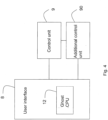
- the control unit consists of a logic block 7 and an IOC block 6, which communicate with each other through the communication bus 2.
- FIG. 3 is a block diagram and represents a minimum configuration of the control unit of the present invention.
- Fig. 3 illustrates the concept of producing functional subsystems that interact with one another: it will thus be possible to provide a control unit with more than one logic block 7 and/or IOC block 6.
- the logic block comprises one or more processing boards 1 and can optionally comprise a control unit inter-connection board 70 for transmission/ reception.
- the processing board 1 implements the main functionalities of the whole safety system. At least one processing board 1 is essential for operation of the system. Additional processing boards allow different degrees of redundancy to be obtained so as to satisfy the specific requirements of the level of safety established for the particular system. In normal operations, the processing board 1 acquires the inputs from the input boards 3 responsible for detection, implements the safety function and then produces all the outputs towards the output boards 4 responsible for reporting, intervention and/or extinguishing a fire. In the example of embodiment of the figures, up to three processing boards 1 are provided. The system also provides a software tool utilized to produce the specific safety function for the system, in which a configuration file of is exported and loaded into the processing board 1 through a serial communication.
- the control unit inter-connection board 70 for transmission/reception has the task of virtualizing the computational resources. For example, if in a control unit all the processing boards 1 are deactivated, the control unit inter-connection board 70 for transmission/reception identifies the computational resource in a remote processing board 7', for example on another physically distinct and optionally remote control unit, and shares it with the input and output boards that require computational capacities.
- control unit inter-connection board 70 for transmission/reception thus allows a virtualization of the resources and, in accordance with the configuration illustrated in Fig. 3 , the control unit inter-connection board 70 for transmission/reception belongs to the logic block 7, but forms an independent subsystem, also having its own logic and communication means 75' to the communication bus 2.
- control unit inter-connection board 70 The union of the control unit inter-connection board 70 and of the logic block 7, thus allows the production of a functional subsystem, i.e., of a local computational cluster, capable of remotely processing the data detected by the field boards.
- the remote processing board 7' is a specialized CPU board that allows "mirroring” and “shadowing” operations of the logic resources of the whole system.
- any bus linked to the remote CPU 7' can in fact be conveyed, all or in part, on the control unit inter-connection.
- the communication bus 2 is based on the architecture of an HDLC link (High-Level Data Link Control), with a specific interrupt management for the typical requirements of a fire-prevention system and integrating a specific block for mapping and diagnostics of the physical links of the system.
- the communication bus 2 operates in multimaster mode and, therefore, overcomes the limits of known systems in which the obligatory passage of all the data in a controller, or concentrator, makes this node particularly critical.
- the communication bus 2 is not completely synchronous and is provided with a specific communication protocol manager. This protocol integrates operating modes oriented towards connection and allows the coexistence of types of communication, even differing from one another, on the basis of a priority management.
- the communication bus 2 comprises two communication channels and, therefore, contributes to the redundancy of the system. As the communication bus 2 is dual, it is possible to divert a communication onto one channel or onto the other, so as to make full use of the resources.
- a user interface block 8 is also connected to the communication bus 2. Said user interface 8 manages all the reporting, notification, control and interface functions toward an operator.
- the user interface block 8 comprises a panel 80, described below in relation to Fig. 7 , and a data collection and processing board for the interface 82.
- the logic block 7, the IOC block 6 and the user interface 8 communicate with the bus 2 through means for direct communication with the bus, 75, 65 and 85 respectively.
- the data collection and processing board for the interface 82 does not dialog directly with the processing board 1, but, on the contrary, collects and processes the information present on the bus 2.
- the data collection and processing board 82 thus operates on the same data available to the CPU of the logic block 7, but without directly involving the same CPU.
- the system is provided with a power supply module comprising a line commutated power supply and a battery charger provided for a secondary source consisting of auxiliary batteries.
- Fig. 4 illustrates a possible embodiment of the system, in which the control unit 9 is backed up by an additional control unit 90.
- the system can accommodate further additional support frames, for example up to seven, to extend the functionality and the number of boards installable.
- ghost CPU 12 allows the commands to be operated remotely and, therefore, allows the system to be freed from this component.
- the ghost CPU 12 does not interrogate the processing board 1 of the control unit, but, on the contrary, collects and processes the data from the communication bus 2 directly.
- Fig. 5 illustrates Logic Solver unit 11 of the control unit, which consists of an independent logic unit which is part of the processing board 1.
- this is a hardware block written in VHDL language which allows the implementation of a computational logic residing in the processing boards 1, particularly efficient in the field of functional safety.
- the internal architecture implemented allows rapid reaction to system events (controlled by events) dictated by fire-prevention regulations, so as to minimize the logic paths required.
- the aforesaid solver unit 11 is a programmable hardware processor that, with a minimum set of instructions, performs computational logics critical in the field of safety, allowing the implementation of logics that can also be personalized by a user, as well as the dedicated functional logic blocks responding to fire-prevention regulations.
- the computational performance is very high and is obtained by releasing the setup files from those containing the instructions.
- Operation is based on the method of resource addressing, through a system of "mirroring" and virtualization of the address space, including the computational-logic ones. This approach, combined with the system bus, allows the implementation of ESC dynamic functional clusters through real time reorganization of the resources, also between several interconnected control units, promoting the "availability" of the system and ensuring its operation even in the case of possible faults.
- a diagnostic, supervision and arbitration functionality is also provided, controlled by a mapping unit called device mapper.
- the device mapper allows advanced arbitration and control functionalities on the computational paths to be provided.
- the logic behaviour of the system can be reprogrammed to meet different regulations and standards in the field of fire-prevention.
- the solver unit 11 operates on an input vector 12 and an output vector 13.
- the data processed by the solver unit 11 are supplied to the output vector 13 that, through the device mapper, is wired directly to the output board 4.
- the addressing space of these vectors can be virtualized so as to be correlated to physical devices on the control unit or to devices controlled by external units such as in the case of inter-connected units or units for importing/exporting variables from and to other systems.
- the solver unit 11 can be programmed by means of an instruction file 14.
- the architecture of the processing board 1, or CPU also comprises a dynamic mapping operator of the devices connected and configured and a comparative diagnostic mechanism. Therefore, the processing board 1 implements different data communication standards so as to import and export any information and rules from or to the additional external electronic systems.
- the CPU board 1 also has a non-volatile memory in which a configuration file with the parameters related to the settings for the specific installation resides.
- this file is cross-correlated between the different subsystems so as to eliminate any problem of integrity of the data.
- the diagnostic system supervises normal operation, analysing each operating parameter from the power supply voltages to the temperature of the printed circuit and, after having evaluated the configuration, decides what the operating status of the two logics should be.
- Fig. 6 illustrates a diagram of the diagnostic functionality of each board.
- each circuit board has an independent operating logic, also with an independent part of diagnostics.
- an input board 3 in the figure a control vector 32 on which a redundancy value is calculated is generated.
- this redundancy value is obtained by a configuration vector 31 and by an input vector 30 (or optionally output vector, according to whether it is an input or an output board, respectively).
- calculation of the redundancy value uses the CRC32 algorithm.
- Said redundancy value is available at a processing board 1, which compares it with an expected value contained in a reference vector 33. In this way, in the case in which a computation resource is absent, for example due to physical disconnection of one of the circuit boards, when it becomes available again it is not necessary to reinitialize this board.
- each input board consists of a circuit board, dedicated to the acquisition of digital or analog input devices and/or circuits, which uses a dual loop for current reading and Class II insulation.
- the configuration of the board provides for different operating modes according to the device or to the detection circuit to be used. In fact, line control, automatic reset, direct reading, selective status storage, 2/4 wire interface with separate power supply and differential current control to facilitate any ground leakages are possible.
- This board can universally acquire analog voltage or current levels or configurable on discrimination intervals, also for overlappable thresholds, facilitating the creation of safety logics.
- the aforesaid architecture makes it universal, allowing it to adapt to a plurality of circuit configurations.
- the channels of the board are monitored and calibrated at time intervals. In the case in which an internal fault to the circuits of the board occurs, the channel is made to operate through a single current loop and the fault is reported promptly for replacement. In the case in which the redundant part of the channel is also unable to operate correctly and the detection circuit has no further boards in parallel on the given device, it is put out of use and must be replaced as soon as possible.
- a circuit board is advantageously provided, designated with controlling analog or digital output devices even with noteworthy energy absorption.
- the board is based on an architecture with dual logic in non-blocking configuration.
- the part dedicated to the field devices utilizes power H bridges and a dual system for reading the current to the load.
- the board offers up to 16 single channels configurable and joinable so as to reach control capacities of up to 2.5A (maximum 4 HC channels) continuous on the load.
- the different configurations of the channels provide for normal or inverse control of the line, control of the current and of the energy on the load, proportional activation of the load by means of PWM and selective status storage.
- a monitoring and calibration system of the channels performs the diagnostics and in the case of an internal fault switches operation onto the redundant part. Also for this board it is possible to join different channels also of different boards on a single circuit or activation device so as to use redundancy of a degree greater than 2.
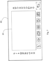
- Fig. 7 illustrates an embodiment of the interface panel 80.
- the panel 80 is provided with touch function keys, as in the example illustrated, high contrast LEDs for reporting the system statuses, twenty in the example illustrated, and a display 81, preferably a touch screen, for advanced management of the various configurations, of the system maps, of the operations and of the event history of the system.
- operator access to the control unit is managed with different access levels corresponding to given settings.
- Identification of a user, and therefore of the related access level allocated, is implemented via password or, preferably, a magnetic card provided with a transponder of RFID type.
Landscapes
- Engineering & Computer Science (AREA)
- Theoretical Computer Science (AREA)
- Physics & Mathematics (AREA)
- General Physics & Mathematics (AREA)
- General Engineering & Computer Science (AREA)
- Quality & Reliability (AREA)
- Computer Security & Cryptography (AREA)
- Computing Systems (AREA)
- Signal Processing (AREA)
- Computer Networks & Wireless Communication (AREA)
- Emergency Management (AREA)
- Mathematical Physics (AREA)
- Business, Economics & Management (AREA)
- Alarm Systems (AREA)
- Fire-Extinguishing Compositions (AREA)
- Hardware Redundancy (AREA)
Claims (10)
- Unité de commande anti-incendie comprenant plusieurs cartes de circuits imprimés (1, 3, 4) et un bus de communication dédié (2) pour la communication entre lesdites cartes de circuits imprimés, lesdites cartes de circuits imprimés comprenant au moins une carte de traitement (1), au moins une carte d'entrée (3) et au moins une carte de sortie (4), ladite carte de traitement (1) au minimum étant destinée à traiter les données d'entrée reçues de ladite carte d'entrée (3) au minimum et à générer des commandes à envoyer à ladite carte de sortie (4) au minimum, ladite carte d'entrée (3) au minimum et ladite carte de sortie (4) au minimum étant configurées pour communiquer avec un ou plusieurs dispositifs à surveiller ou à commander, caractérisée par le fait que chaque carte de circuit (1, 3, 4) comprend deux unités logiques fonctionnelles (10) substantiellement identiques et physiquement distinctes, lesdites unités logiques fonctionnelles (10) étant adaptées pour exécuter la même fonction et où chaque unité logique fonctionnelle (10) comprend des moyens de communication directe avec le bus de communication (2).
- Unité de commande anti-incendie selon la revendication 1, dans laquelle ledit bus de communication (2) comprend au moins deux canaux de communication, chaque canal de communication étant configuré pour permettre la communication entre lesdites cartes de circuits imprimés (1, 3, 4).
- Unité de commande anti-incendie selon la revendication 1 ou 2, où le bus de communication (2) est configuré pour hiérarchiser les données communiquées par les cartes.
- Unité de commande anti-incendie selon la revendication 1, où chaque unité logique fonctionnelle (10) comprend un circuit intégré programmable de type FPGA (Field Programmable Gate Array).
- Unité de commande anti-incendie selon l'une ou plusieurs des revendications précédentes, comprenant au moins une unité d'interface utilisateur (8) connectée directement audit bus de communication (2).
- Unité de commande anti-incendie selon une ou plusieurs des revendications précédentes, où lesdites cartes d'entrée (3) et lesdites cartes de sortie (4) comprennent des moyens pour générer un code de commande calculé sur la base d'un vecteur d'entrée ou de sortie et d'un vecteur de configuration de la carte, ledit code de commande étant accessible au moins à partir de ladite carte de traitement (1) pour effectuer un test de comparaison de cohérence avec un code de commande attendu correspondant.
- Unité de commande anti-incendie selon l'une ou plusieurs des revendications précédentes, où les cartes de circuits imprimés (1, 3, 4) comprennent une carte d'interconnexion (70) de l'unité de commande, permettant la communication par au moins une carte d'entrée (3) ou au moins une carte de sortie (4), avec une unité de traitement ou une unité de calcul distante.
- Système anti-incendie comprenant au moins une unité principale de commande anti-incendie selon les revendications précédentes 1 à 7 et au moins une unité d'interface utilisateur (8).
- Système anti-incendie selon la revendication 8, dans lequel ladite unité d'interface utilisateur comprend au moins une unité de traitement, configurée pour gérer la communication de ladite unité d'interface utilisateur avec le bus de communication, et au moins une unité d'affichage indépendante de l'unité logique de commande..
- Système anti-incendie selon la revendication 8 ou 9, comprenant une unité de commande secondaire ou d'expansion locale, connectée à ladite unité de commande anti-incendie principale, ladite unité de commande secondaire ou d'expansion locale étant équipée d'au moins une carte de circuit d'entrée et d'au moins une carte de circuit de sortie.
Applications Claiming Priority (2)
| Application Number | Priority Date | Filing Date | Title |
|---|---|---|---|
| IT102016000127390A IT201600127390A1 (it) | 2016-12-16 | 2016-12-16 | Centrale antincendio |
| PCT/IB2017/058005 WO2018109739A1 (fr) | 2016-12-16 | 2017-12-15 | Unité de commande anti-incendie |
Publications (3)
| Publication Number | Publication Date |
|---|---|
| EP3555871A1 EP3555871A1 (fr) | 2019-10-23 |
| EP3555871C0 EP3555871C0 (fr) | 2024-02-21 |
| EP3555871B1 true EP3555871B1 (fr) | 2024-02-21 |
Family
ID=58638938
Family Applications (1)
| Application Number | Title | Priority Date | Filing Date |
|---|---|---|---|
| EP17829701.6A Active EP3555871B1 (fr) | 2016-12-16 | 2017-12-15 | Unité de commande anti-incendie |
Country Status (5)
| Country | Link |
|---|---|
| US (1) | US10991235B2 (fr) |
| EP (1) | EP3555871B1 (fr) |
| CN (1) | CN110114805B (fr) |
| IT (1) | IT201600127390A1 (fr) |
| WO (1) | WO2018109739A1 (fr) |
Families Citing this family (1)
| Publication number | Priority date | Publication date | Assignee | Title |
|---|---|---|---|---|
| JP6965767B2 (ja) * | 2018-01-23 | 2021-11-10 | 株式会社デンソー | 車載通信システム |
Citations (3)
| Publication number | Priority date | Publication date | Assignee | Title |
|---|---|---|---|---|
| US20020180598A1 (en) * | 2001-06-02 | 2002-12-05 | Anton Pfefferseder | Danger detecting system |
| WO2006119323A2 (fr) * | 2005-05-03 | 2006-11-09 | Palomar Technology, Llc | Systeme et procede de surveillance fiables |
| EP2423897A2 (fr) * | 2010-08-26 | 2012-02-29 | Novar GmbH | Installation d'alerte aux dangers et son procédé de fonctionnement |
Family Cites Families (22)
| Publication number | Priority date | Publication date | Assignee | Title |
|---|---|---|---|---|
| JP2664144B2 (ja) * | 1986-01-16 | 1997-10-15 | 株式会社日立製作所 | 多重化処理装置の切替方法および装置 |
| US6844823B2 (en) * | 1999-02-10 | 2005-01-18 | Symon Communications, Inc. | Method and apparatus for providing power to a visual messaging system for high-speed networks |
| US6768423B2 (en) * | 2002-02-21 | 2004-07-27 | Case Corporation | Cab environment warning and control method and apparatus |
| WO2004005938A1 (fr) * | 2002-07-04 | 2004-01-15 | Siemens Aktiengesellschaft | Dispositif permettant de determiner la vitesse de rotation d'une partie de machine en rotation a l'aide de capteurs redondants et de circuits d'evaluation |
| US7032135B2 (en) * | 2002-08-02 | 2006-04-18 | Corrigent Systems Ltd. | Equipment protection using a partial star architecture |
| JP5200396B2 (ja) * | 2007-03-16 | 2013-06-05 | 株式会社リコー | 画像形成装置、画像処理装置、制御装置、及び、接続装置 |
| US20110307746A1 (en) * | 2010-06-07 | 2011-12-15 | Sullivan Jason A | Systems and Methods for Intelligent and Flexible Management and Monitoring of Computer Systems |
| US9118213B2 (en) * | 2010-11-24 | 2015-08-25 | Kohler Co. | Portal for harvesting energy from distributed electrical power sources |
| US20130282946A1 (en) * | 2012-04-23 | 2013-10-24 | Flextronics Ap, Llc | Controller area network bus |
| EP2595018B1 (fr) * | 2011-11-17 | 2019-01-23 | Rockwell Automation Limited | Procédé et appareil de contrôle du courant de sortie analogique |
| CN104299350B (zh) * | 2014-09-02 | 2016-08-24 | 杭州航海仪器有限公司 | 一种多冗余可变主从火灾预警监控系统及方法 |
| CN105550074B (zh) * | 2015-12-08 | 2018-06-19 | 中国计量大学 | 航天计算机 |
| CN105550053B (zh) * | 2015-12-09 | 2018-08-21 | 中国航空工业集团公司西安航空计算技术研究所 | 一种提升可用性的监控对容错系统余度管理方法 |
| US9898934B2 (en) * | 2016-07-25 | 2018-02-20 | Honeywell International Inc. | Prediction of vehicle maneuvers |
| US11301020B2 (en) * | 2017-05-22 | 2022-04-12 | Intel Corporation | Data center power management |
| US11194753B2 (en) * | 2017-09-01 | 2021-12-07 | Intel Corporation | Platform interface layer and protocol for accelerators |
| US20190108111A1 (en) * | 2017-10-06 | 2019-04-11 | Intel Corporation | Bit error rate prediction |
| US11153211B2 (en) * | 2017-12-09 | 2021-10-19 | Intel Corporation | Fast data center congestion response |
| US10599548B2 (en) * | 2018-06-28 | 2020-03-24 | Intel Corporation | Cache monitoring |
| US20190042339A1 (en) * | 2018-06-29 | 2019-02-07 | Intel Corporation | Techniques for invocation of a function or a service |
| US11303638B2 (en) * | 2018-06-29 | 2022-04-12 | Intel Corporation | Atomic update of access control list rules |
| US10838780B2 (en) * | 2018-12-10 | 2020-11-17 | Mcafee, Llc | Portable hosted content |
-
2016
- 2016-12-16 IT IT102016000127390A patent/IT201600127390A1/it unknown
-
2017
- 2017-12-15 US US16/469,730 patent/US10991235B2/en active Active
- 2017-12-15 EP EP17829701.6A patent/EP3555871B1/fr active Active
- 2017-12-15 CN CN201780081713.7A patent/CN110114805B/zh active Active
- 2017-12-15 WO PCT/IB2017/058005 patent/WO2018109739A1/fr unknown
Patent Citations (3)
| Publication number | Priority date | Publication date | Assignee | Title |
|---|---|---|---|---|
| US20020180598A1 (en) * | 2001-06-02 | 2002-12-05 | Anton Pfefferseder | Danger detecting system |
| WO2006119323A2 (fr) * | 2005-05-03 | 2006-11-09 | Palomar Technology, Llc | Systeme et procede de surveillance fiables |
| EP2423897A2 (fr) * | 2010-08-26 | 2012-02-29 | Novar GmbH | Installation d'alerte aux dangers et son procédé de fonctionnement |
Also Published As
| Publication number | Publication date |
|---|---|
| EP3555871A1 (fr) | 2019-10-23 |
| WO2018109739A1 (fr) | 2018-06-21 |
| CN110114805A (zh) | 2019-08-09 |
| US10991235B2 (en) | 2021-04-27 |
| EP3555871C0 (fr) | 2024-02-21 |
| US20190362620A1 (en) | 2019-11-28 |
| CN110114805B (zh) | 2021-03-02 |
| IT201600127390A1 (it) | 2018-06-16 |
Similar Documents
| Publication | Publication Date | Title |
|---|---|---|
| CN103544092B (zh) | 一种基于arinc653标准机载电子设备健康监控系统 | |
| CN110376876B (zh) | 一种双系同步的安全计算机平台 | |
| CN110351174B (zh) | 一种模块冗余的安全计算机平台 | |
| US6466539B1 (en) | Bus system | |
| CN201909961U (zh) | 一种冗余控制系统 | |
| US9934111B2 (en) | Control and data transmission system, process device, and method for redundant process control with decentralized redundancy | |
| CN110361979A (zh) | 一种铁路信号领域的安全计算机平台 | |
| KR101179782B1 (ko) | 원자력 발전소 안전계통의 안전등급 통신 스위치 | |
| CN105045164A (zh) | 可降级的三冗余同步表决计算机控制系统及方法 | |
| CN111007790B (zh) | 船舶损管监控可靠性改善设计系统及方法 | |
| CN104977907A (zh) | 直接连接算法 | |
| CN105005232A (zh) | 可降级的三冗余同步表决计算机控制系统及方法 | |
| US11169491B2 (en) | Safety switch | |
| KR101469179B1 (ko) | 원자력 발전 시뮬레이터의 통신 진단 시스템 | |
| EP3555871B1 (fr) | Unité de commande anti-incendie | |
| JP2013201664A (ja) | 冗長通信装置 | |
| KR102333907B1 (ko) | 원자력 발전소의 안전을 위한 제어시스템 | |
| CN102088366B (zh) | 一种单板信息监控装置及分布式单板信息监控系统 | |
| CN115705267A (zh) | 监控采集设备、基于监控采集设备的主备切换方法及系统 | |
| CN109284218A (zh) | 一种检测服务器运行故障的方法及其装置 | |
| JPH08237762A (ja) | ビル管理システム | |
| KR20210025823A (ko) | 장비 및 설비의 이상유무 점검 시스템 | |
| KR101779117B1 (ko) | 원격 감시 및 제어용 인터페이스 장치 | |
| CN104077205B (zh) | 一种基于多种外设的完全热备份告警设备及其调度方法 | |
| CN220455472U (zh) | 一种开关检测装置和机器人 |
Legal Events
| Date | Code | Title | Description |
|---|---|---|---|
| STAA | Information on the status of an ep patent application or granted ep patent |
Free format text: STATUS: UNKNOWN |
|
| STAA | Information on the status of an ep patent application or granted ep patent |
Free format text: STATUS: THE INTERNATIONAL PUBLICATION HAS BEEN MADE |
|
| PUAI | Public reference made under article 153(3) epc to a published international application that has entered the european phase |
Free format text: ORIGINAL CODE: 0009012 |
|
| STAA | Information on the status of an ep patent application or granted ep patent |
Free format text: STATUS: REQUEST FOR EXAMINATION WAS MADE |
|
| 17P | Request for examination filed |
Effective date: 20190712 |
|
| AK | Designated contracting states |
Kind code of ref document: A1 Designated state(s): AL AT BE BG CH CY CZ DE DK EE ES FI FR GB GR HR HU IE IS IT LI LT LU LV MC MK MT NL NO PL PT RO RS SE SI SK SM TR |
|
| AX | Request for extension of the european patent |
Extension state: BA ME |
|
| DAV | Request for validation of the european patent (deleted) | ||
| DAX | Request for extension of the european patent (deleted) | ||
| STAA | Information on the status of an ep patent application or granted ep patent |
Free format text: STATUS: EXAMINATION IS IN PROGRESS |
|
| STAA | Information on the status of an ep patent application or granted ep patent |
Free format text: STATUS: EXAMINATION IS IN PROGRESS |
|
| 17Q | First examination report despatched |
Effective date: 20211011 |
|
| 17Q | First examination report despatched |
Effective date: 20211029 |
|
| GRAP | Despatch of communication of intention to grant a patent |
Free format text: ORIGINAL CODE: EPIDOSNIGR1 |
|
| STAA | Information on the status of an ep patent application or granted ep patent |
Free format text: STATUS: GRANT OF PATENT IS INTENDED |
|
| INTG | Intention to grant announced |
Effective date: 20231026 |
|
| GRAS | Grant fee paid |
Free format text: ORIGINAL CODE: EPIDOSNIGR3 |
|
| GRAA | (expected) grant |
Free format text: ORIGINAL CODE: 0009210 |
|
| STAA | Information on the status of an ep patent application or granted ep patent |
Free format text: STATUS: THE PATENT HAS BEEN GRANTED |
|
| AK | Designated contracting states |
Kind code of ref document: B1 Designated state(s): AL AT BE BG CH CY CZ DE DK EE ES FI FR GB GR HR HU IE IS IT LI LT LU LV MC MK MT NL NO PL PT RO RS SE SI SK SM TR |
|
| REG | Reference to a national code |
Ref country code: GB Ref legal event code: FG4D |
|
| REG | Reference to a national code |
Ref country code: CH Ref legal event code: EP |
|
| REG | Reference to a national code |
Ref country code: IE Ref legal event code: FG4D |
|
| REG | Reference to a national code |
Ref country code: DE Ref legal event code: R096 Ref document number: 602017079397 Country of ref document: DE |
|
| U01 | Request for unitary effect filed |
Effective date: 20240320 |
|
| U07 | Unitary effect registered |
Designated state(s): AT BE BG DE DK EE FI FR IT LT LU LV MT NL PT SE SI Effective date: 20240416 |
|
| PG25 | Lapsed in a contracting state [announced via postgrant information from national office to epo] |
Ref country code: IS Free format text: LAPSE BECAUSE OF FAILURE TO SUBMIT A TRANSLATION OF THE DESCRIPTION OR TO PAY THE FEE WITHIN THE PRESCRIBED TIME-LIMIT Effective date: 20240621 |
|
| PG25 | Lapsed in a contracting state [announced via postgrant information from national office to epo] |
Ref country code: GR Free format text: LAPSE BECAUSE OF FAILURE TO SUBMIT A TRANSLATION OF THE DESCRIPTION OR TO PAY THE FEE WITHIN THE PRESCRIBED TIME-LIMIT Effective date: 20240522 |
|
| PG25 | Lapsed in a contracting state [announced via postgrant information from national office to epo] |
Ref country code: RS Free format text: LAPSE BECAUSE OF FAILURE TO SUBMIT A TRANSLATION OF THE DESCRIPTION OR TO PAY THE FEE WITHIN THE PRESCRIBED TIME-LIMIT Effective date: 20240521 Ref country code: HR Free format text: LAPSE BECAUSE OF FAILURE TO SUBMIT A TRANSLATION OF THE DESCRIPTION OR TO PAY THE FEE WITHIN THE PRESCRIBED TIME-LIMIT Effective date: 20240221 |
|
| PG25 | Lapsed in a contracting state [announced via postgrant information from national office to epo] |
Ref country code: ES Free format text: LAPSE BECAUSE OF FAILURE TO SUBMIT A TRANSLATION OF THE DESCRIPTION OR TO PAY THE FEE WITHIN THE PRESCRIBED TIME-LIMIT Effective date: 20240221 |
|
| PG25 | Lapsed in a contracting state [announced via postgrant information from national office to epo] |
Ref country code: RS Free format text: LAPSE BECAUSE OF FAILURE TO SUBMIT A TRANSLATION OF THE DESCRIPTION OR TO PAY THE FEE WITHIN THE PRESCRIBED TIME-LIMIT Effective date: 20240521 Ref country code: NO Free format text: LAPSE BECAUSE OF FAILURE TO SUBMIT A TRANSLATION OF THE DESCRIPTION OR TO PAY THE FEE WITHIN THE PRESCRIBED TIME-LIMIT Effective date: 20240521 Ref country code: IS Free format text: LAPSE BECAUSE OF FAILURE TO SUBMIT A TRANSLATION OF THE DESCRIPTION OR TO PAY THE FEE WITHIN THE PRESCRIBED TIME-LIMIT Effective date: 20240621 Ref country code: HR Free format text: LAPSE BECAUSE OF FAILURE TO SUBMIT A TRANSLATION OF THE DESCRIPTION OR TO PAY THE FEE WITHIN THE PRESCRIBED TIME-LIMIT Effective date: 20240221 Ref country code: GR Free format text: LAPSE BECAUSE OF FAILURE TO SUBMIT A TRANSLATION OF THE DESCRIPTION OR TO PAY THE FEE WITHIN THE PRESCRIBED TIME-LIMIT Effective date: 20240522 Ref country code: ES Free format text: LAPSE BECAUSE OF FAILURE TO SUBMIT A TRANSLATION OF THE DESCRIPTION OR TO PAY THE FEE WITHIN THE PRESCRIBED TIME-LIMIT Effective date: 20240221 |
|
| PG25 | Lapsed in a contracting state [announced via postgrant information from national office to epo] |
Ref country code: PL Free format text: LAPSE BECAUSE OF FAILURE TO SUBMIT A TRANSLATION OF THE DESCRIPTION OR TO PAY THE FEE WITHIN THE PRESCRIBED TIME-LIMIT Effective date: 20240221 |
|
| PG25 | Lapsed in a contracting state [announced via postgrant information from national office to epo] |
Ref country code: PL Free format text: LAPSE BECAUSE OF FAILURE TO SUBMIT A TRANSLATION OF THE DESCRIPTION OR TO PAY THE FEE WITHIN THE PRESCRIBED TIME-LIMIT Effective date: 20240221 |