EP3555499B1 - Halbautomatisches getriebe - Google Patents
Halbautomatisches getriebe Download PDFInfo
- Publication number
- EP3555499B1 EP3555499B1 EP17794031.9A EP17794031A EP3555499B1 EP 3555499 B1 EP3555499 B1 EP 3555499B1 EP 17794031 A EP17794031 A EP 17794031A EP 3555499 B1 EP3555499 B1 EP 3555499B1
- Authority
- EP
- European Patent Office
- Prior art keywords
- washer
- teeth
- transmission according
- tabs
- elastic
- Prior art date
- Legal status (The legal status is an assumption and is not a legal conclusion. Google has not performed a legal analysis and makes no representation as to the accuracy of the status listed.)
- Active
Links
Images



Classifications
-
- F—MECHANICAL ENGINEERING; LIGHTING; HEATING; WEAPONS; BLASTING
- F16—ENGINEERING ELEMENTS AND UNITS; GENERAL MEASURES FOR PRODUCING AND MAINTAINING EFFECTIVE FUNCTIONING OF MACHINES OR INSTALLATIONS; THERMAL INSULATION IN GENERAL
- F16H—GEARING
- F16H61/00—Control functions within control units of change-speed- or reversing-gearings for conveying rotary motion ; Control of exclusively fluid gearing, friction gearing, gearings with endless flexible members or other particular types of gearing
- F16H61/02—Control functions within control units of change-speed- or reversing-gearings for conveying rotary motion ; Control of exclusively fluid gearing, friction gearing, gearings with endless flexible members or other particular types of gearing characterised by the signals used
- F16H61/0202—Control functions within control units of change-speed- or reversing-gearings for conveying rotary motion ; Control of exclusively fluid gearing, friction gearing, gearings with endless flexible members or other particular types of gearing characterised by the signals used the signals being electric
- F16H61/0204—Control functions within control units of change-speed- or reversing-gearings for conveying rotary motion ; Control of exclusively fluid gearing, friction gearing, gearings with endless flexible members or other particular types of gearing characterised by the signals used the signals being electric for gearshift control, e.g. control functions for performing shifting or generation of shift signal
-
- F—MECHANICAL ENGINEERING; LIGHTING; HEATING; WEAPONS; BLASTING
- F16—ENGINEERING ELEMENTS AND UNITS; GENERAL MEASURES FOR PRODUCING AND MAINTAINING EFFECTIVE FUNCTIONING OF MACHINES OR INSTALLATIONS; THERMAL INSULATION IN GENERAL
- F16D—COUPLINGS FOR TRANSMITTING ROTATION; CLUTCHES; BRAKES
- F16D23/00—Details of mechanically-actuated clutches not specific for one distinct type
- F16D23/02—Arrangements for synchronisation, also for power-operated clutches
- F16D23/04—Arrangements for synchronisation, also for power-operated clutches with an additional friction clutch
-
- F—MECHANICAL ENGINEERING; LIGHTING; HEATING; WEAPONS; BLASTING
- F16—ENGINEERING ELEMENTS AND UNITS; GENERAL MEASURES FOR PRODUCING AND MAINTAINING EFFECTIVE FUNCTIONING OF MACHINES OR INSTALLATIONS; THERMAL INSULATION IN GENERAL
- F16H—GEARING
- F16H63/00—Control outputs from the control unit to change-speed- or reversing-gearings for conveying rotary motion or to other devices than the final output mechanism
- F16H63/02—Final output mechanisms therefor; Actuating means for the final output mechanisms
- F16H63/30—Constructional features of the final output mechanisms
-
- F—MECHANICAL ENGINEERING; LIGHTING; HEATING; WEAPONS; BLASTING
- F16—ENGINEERING ELEMENTS AND UNITS; GENERAL MEASURES FOR PRODUCING AND MAINTAINING EFFECTIVE FUNCTIONING OF MACHINES OR INSTALLATIONS; THERMAL INSULATION IN GENERAL
- F16H—GEARING
- F16H63/00—Control outputs from the control unit to change-speed- or reversing-gearings for conveying rotary motion or to other devices than the final output mechanism
- F16H63/02—Final output mechanisms therefor; Actuating means for the final output mechanisms
- F16H63/30—Constructional features of the final output mechanisms
- F16H63/38—Detents
-
- B—PERFORMING OPERATIONS; TRANSPORTING
- B60—VEHICLES IN GENERAL
- B60Y—INDEXING SCHEME RELATING TO ASPECTS CROSS-CUTTING VEHICLE TECHNOLOGY
- B60Y2400/00—Special features of vehicle units
- B60Y2400/42—Clutches or brakes
- B60Y2400/421—Dog type clutches or brakes
-
- F—MECHANICAL ENGINEERING; LIGHTING; HEATING; WEAPONS; BLASTING
- F16—ENGINEERING ELEMENTS AND UNITS; GENERAL MEASURES FOR PRODUCING AND MAINTAINING EFFECTIVE FUNCTIONING OF MACHINES OR INSTALLATIONS; THERMAL INSULATION IN GENERAL
- F16D—COUPLINGS FOR TRANSMITTING ROTATION; CLUTCHES; BRAKES
- F16D23/00—Details of mechanically-actuated clutches not specific for one distinct type
- F16D23/02—Arrangements for synchronisation, also for power-operated clutches
- F16D23/04—Arrangements for synchronisation, also for power-operated clutches with an additional friction clutch
- F16D23/06—Arrangements for synchronisation, also for power-operated clutches with an additional friction clutch and a blocking mechanism preventing the engagement of the main clutch prior to synchronisation
- F16D2023/0631—Sliding sleeves; Details thereof
-
- F—MECHANICAL ENGINEERING; LIGHTING; HEATING; WEAPONS; BLASTING
- F16—ENGINEERING ELEMENTS AND UNITS; GENERAL MEASURES FOR PRODUCING AND MAINTAINING EFFECTIVE FUNCTIONING OF MACHINES OR INSTALLATIONS; THERMAL INSULATION IN GENERAL
- F16D—COUPLINGS FOR TRANSMITTING ROTATION; CLUTCHES; BRAKES
- F16D23/00—Details of mechanically-actuated clutches not specific for one distinct type
- F16D23/02—Arrangements for synchronisation, also for power-operated clutches
- F16D23/04—Arrangements for synchronisation, also for power-operated clutches with an additional friction clutch
- F16D23/06—Arrangements for synchronisation, also for power-operated clutches with an additional friction clutch and a blocking mechanism preventing the engagement of the main clutch prior to synchronisation
- F16D2023/0656—Details of the tooth structure; Arrangements of teeth
-
- F—MECHANICAL ENGINEERING; LIGHTING; HEATING; WEAPONS; BLASTING
- F16—ENGINEERING ELEMENTS AND UNITS; GENERAL MEASURES FOR PRODUCING AND MAINTAINING EFFECTIVE FUNCTIONING OF MACHINES OR INSTALLATIONS; THERMAL INSULATION IN GENERAL
- F16D—COUPLINGS FOR TRANSMITTING ROTATION; CLUTCHES; BRAKES
- F16D23/00—Details of mechanically-actuated clutches not specific for one distinct type
- F16D23/02—Arrangements for synchronisation, also for power-operated clutches
- F16D23/04—Arrangements for synchronisation, also for power-operated clutches with an additional friction clutch
- F16D23/06—Arrangements for synchronisation, also for power-operated clutches with an additional friction clutch and a blocking mechanism preventing the engagement of the main clutch prior to synchronisation
- F16D2023/0687—Clutches with electrical actuation
-
- F—MECHANICAL ENGINEERING; LIGHTING; HEATING; WEAPONS; BLASTING
- F16—ENGINEERING ELEMENTS AND UNITS; GENERAL MEASURES FOR PRODUCING AND MAINTAINING EFFECTIVE FUNCTIONING OF MACHINES OR INSTALLATIONS; THERMAL INSULATION IN GENERAL
- F16H—GEARING
- F16H63/00—Control outputs from the control unit to change-speed- or reversing-gearings for conveying rotary motion or to other devices than the final output mechanism
- F16H63/02—Final output mechanisms therefor; Actuating means for the final output mechanisms
- F16H63/30—Constructional features of the final output mechanisms
- F16H2063/3089—Spring assisted shift, e.g. springs for accumulating energy of shift movement and release it when clutch teeth are aligned
-
- F—MECHANICAL ENGINEERING; LIGHTING; HEATING; WEAPONS; BLASTING
- F16—ENGINEERING ELEMENTS AND UNITS; GENERAL MEASURES FOR PRODUCING AND MAINTAINING EFFECTIVE FUNCTIONING OF MACHINES OR INSTALLATIONS; THERMAL INSULATION IN GENERAL
- F16H—GEARING
- F16H2306/00—Shifting
- F16H2306/40—Shifting activities
- F16H2306/46—Uncoupling of current gear
Definitions
- International demand WO2015 / 067861 relates to a gear change control in a gearbox with parallel shafts and provided with an electric actuator for controlling the gear changes. It relates more specifically to a method of regulating a motorized sliding gear shift actuator, comprising a control element of a spring-assisted mechanical assistance system, capable of initially accumulating energy when the teeth of the walkman come in abutment against those of the clutch pinion to shift a gear, and to restore this energy by relaxation in a second step, to assist the engagement of the teeth of the sliding gear between those of the pinion.
- the passage of a gear is obtained by the sliding of a sliding gear on a hub integral with one of the shafts, the teeth of the sliding gear engaging the teeth of a clutch ring integral with a pinion crazy.
- the player is moved by a fork provided with a position sensor, said fork being driven in translation by the finger of an actuator.
- the return of the player is provided by the fork that moves the player.
- This fork includes a position sensor and is itself driven by the finger of an actuator.
- the stroke of the finger of this actuator is related to the position given by the fork sensor.
- the dispersions of the parts concerned, added to the movements of the shaft lines can be very important, and as a result, the stroke of the actuator finger can in some cases be less than the stroke necessary to fully disengage the teeth of the sliding gear. dog crown teeth.
- the hub balling system is not yet active, the balls not being in the balling slots corresponding to the neutral point of the player. They therefore do not make it possible to bring the latter back to its initial position, and then cause the gearbox to jam.
- a robotic gearbox according to the invention is configured to avoid any blockage when the player must return to neutral position during a release of gear.
- the subject of the invention is a robotic gearbox comprising a hub integral with a shaft, a sliding gear comprising teeth, a dog clutch ring comprising teeth, a idler gear and an actuator, said sliding gear being able to slide on said hub at the by means of a fork provided with a position sensor and driven in translation by a finger of said actuator, and the teeth of said slide being able to engage the teeth of said ring integral with said idler pinion.
- the main characteristic of a gearbox according to the invention is that elastic tabs acting as springs are carried by the dog clutch ring and are arranged on it so as to push the player back when it must return to the point position. dead during a gear release to ensure said position.
- the principle of such a gearbox is to implement simple mechanical means capable of bringing the player systematically and precisely into neutral position, when said position is sought. These means are found in the form of elastic legs, which are initially pre-stressed and which gradually relax as the player approaches the position corresponding to neutral, this relaxation being due to the fact that the legs tend to regain. their natural form.
- These lugs are supported directly or indirectly (by means of an interface part) by the dog clutch and therefore push the player back to its neutral position.
- these tabs are compact to the point of having no influence on the space occupied by the gearbox. Likewise, it is assumed that the presence of the tabs in no way hinders the operation of the gearbox. These tabs act as complements to the actuator, making it possible to overcome the shortcomings of the latter when it is no longer able to provide the necessary travel of the player to reach the neutral position.
- the teeth of the player have an inclined plane, the elastic tabs pushing the player back when they come into contact with said plane.
- the presence of the spring lugs requires a structural modification of the teeth of the player so that the action of said legs is optimum when they push the player back into the neutral position. This modification results in the creation of inclined planes at the level of the teeth of the player, whose interaction with the elastic legs will allow said legs to relax in order to push the player.
- the elastic tabs are integral with an elastic washer capable of coming to press against the dog ring.
- this washer is thin in order to fit easily and simply into the gearbox mechanism without creating any extra thickness. The geometry and dimensions of this washer are dictated by those of the dog gear.
- the elastic tabs and the washer constitute a common part, said tabs being regularly distributed around the washer.
- the washer and the elastic tabs are quick and easy to manufacture. This regular distribution of the tabs around the washer makes it possible to homogenize the pushing force on the player.
- the tabs emerge radially from the washer in a plane inclined with respect to the plane of said washer. In this way, they tend to increase the dimensions of the washer by emerging outwardly from it.
- each of the elastic tabs of the washer is intended to fit into a hollow delimited by an external surface of the dog clutch ring and two successive teeth of said ring, said hollow having an increased depth to allow a space to be left between said elastic tab and said outer surface.
- the elastic tabs will be pre-stressed by the player by pressing against the wall located between two successive teeth of the dog clutch.
- each elastic tab will meet the inclined plane of a tooth of the player and will naturally tend to move away from said wall to regain its initial position. Of this way, by relaxing, the legs will help push the player back to the level of the inclined plane of each tooth.
- the washer and the legs are made of steel.
- the hub has at its periphery orifices each intended to receive a ball, the player comprising neutral ramps each provided with a housing, the neutral position corresponding to a complete insertion of each ball in one. of said housing.
- the ramps can be likened to teeth which extend parallel to the teeth of the player.
- each ball is pushed back from the orifice by means of a spring inserted between said ball and a bottom of said orifice, the hub having three orifices regularly distributed around its periphery.
- the orifices are distributed at 120 ° from each other.
- the orifices are cylindrical and extend radially over the hub.
- the elastic tabs are integral with the dog clutch ring.
- the elastic tabs are each directly secured to the dog clutch ring, and constitute with the latter a common part.
- a gearbox according to the invention has the advantage of systematically and precisely bringing the player into the neutral position, while remaining of a constant size, and without undergoing any structural modification. It also has the advantage of ensuring this additional functionality thanks to a thin elastic washer, made of a common material and whose geometry remains simple.
- a robotized gearbox 1 comprises a hub 2 integral with a shaft, a player 3 capable of slide on said hub 2, and a dog clutch ring 4 integral with an idle pinion 5.
- the player 3 is cylindrical and has a cylindrical internal surface 6 on which are implanted teeth 7 extending along the axis of revolution of said player 3.
- Each of the teeth 7 extends over the entire length of the player 3 which is its dimension considered along its axis of revolution, and are regularly distributed over the entire circumference of said player 3. In other words, the teeth 7 project from the internal surface 6 of player 3 towards the center of said player 3.
- the dog clutch ring 4 is cylindrical and has a cylindrical outer surface 8 on which are implanted teeth 9 extending along the axis of revolution of said ring 4.
- Each of the teeth 9 extends over the entire length of the crown 4, which is its dimension considered along its axis of revolution, and are regularly distributed over the entire circumference of said crown 4. In other words, the teeth 9 project from the external surface 8 of the crown 4 towards the outside of said crown 4.
- the passage of a speed is obtained by the sliding of the sliding gear 3 on the hub 2, the teeth 7 of the sliding mechanism 3 coming to engage the teeth 9 of the clutch crown 4 integral with the idler gear 5.
- the sliding mechanism 3 is moved by a non-rotating fork. visible in the figures and which is provided with a position sensor. This fork is driven in translation by the finger of an electric actuator not visible in the figures.
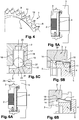
- a robotic gearbox 1 comprises an annular elastic washer 10, and provided with three elastic tabs 11 regularly spaced around said washer 10, forming an angle of 120 ° between them.
- Each elastic tab 11 is elongated and extends radially on the washer 10 along a plane which is inclined relative to the plane of said washer 10. More precisely, the washer 10 is flat and has an internal edge 12 and an external edge 13, each leg 11 being implanted on said outer edge 13 of washer 10 and extends outwardly of said washer 10.
- the free end 14 of each tab 11 is slightly bent with respect to the rest of said tab 11 which is rectilinear.
- the elastic washer 10 has the same dimensions as those of the dog clutch ring 4 and comes to press against it so that each of the three elastic tabs 11 is found in an interval between two successive teeth 9 of said crown 4. Each interval is thus delimited by two successive teeth 9 and by the external surface 8 of the crown 4. In order to leave a free space between each elastic tab 11 and said external surface 8, the crown 4 has been hollowed out between the two teeth 9.
- each tooth 7 of the player 3 extends over the entire length of said player 3 and has a machined end 15 intended to reveal an inclined plane.
- This end 15 is brought to collaborate with the elastic tabs 11 of the elastic washer 10 fixed to the dog clutch ring 4, in order to allow the player 3 to systematically and precisely reach a position corresponding to neutral, when said position is sought.
- the hub 2 comprises three cylindrical and radial orifices 16, arranged regularly on its periphery.
- the orifices 16 are arranged at 120 ° to each other and are each intended to receive a cylindrical balling cartridge 17.
- a balling cartridge 17 comprises a cylindrical case 18, a ball 19 and a prestressed spring (not visible in the figures) inserted between a bottom 20 of the case 18 and said ball 19.
- the diameter of the ball 19 being slightly greater than the opening of the case 18, the spring which tends to push the ball 19 out of the case 18 maintains said ball 19 protruding from said case 18.
- the player 3 comprises three ramps 21 forming between them 120 °, and each having a curved central housing 22 framed by two counter-ramps 23. These three ramps 21 extend parallel to the teeth 7 of the slide 3 and are intended to cooperate with the three balls 19 inserted in the hub 2. Thus, when each of the balls 19 is found entirely in the central housing 22 of a ramp 21, the player 3 is in a position corresponding perfectly to neutral.
- each ball 19 bears against a counter-ramp 23 of a ramp 21 of the player 3 to keep said player 3 in contact with the dog gear 4.
- each elastic tab 11 of the elastic washer 10 is pressed against the external surface 8 of the dog clutch ring 4 by a flat part 24 of a tooth 7 of the slide 3.
- Each elastic tab 11 does not exert any thrust on the slide 3 .
- each ball 19 is found on a flat area 27 of a ramp 21 of the player 3, located between a counter-ramp 23 and the curved central housing 22. Said ball 19 is not active and does not participate in the return of the player 3 on hub 2.
- each elastic tab 11 comes to bear against the inclined end 15 of a tooth 7 of the slide 3 and, in trying to regain its relaxed position, begins to produce a force which pushes the slide 3 back onto the hub 2.
- the said tab 11 contributes to pushing the player 3 towards the hub 2 by assisting the passage actuator.
- the elastic tabs make it possible to compensate for this insufficiency.
- each ball 19 begins to enter the central housing 22 of a ramp 21 of the player 3, and will take over from each elastic tab 11 to bring the player 3 to neutral.
- each elastic tab 11 continues to interact with the inclined end 15 of a tooth 7 of the slide 3 to finish pushing the slide 3 in order to completely remove it from the dog clutch 4.
Landscapes
- Engineering & Computer Science (AREA)
- General Engineering & Computer Science (AREA)
- Mechanical Engineering (AREA)
- Mechanical Operated Clutches (AREA)
Claims (10)
- Automatisiertes Getriebe (1), das eine fest mit einer Welle verbundene Nabe (2), eine Zähne (7) enthaltende Schiebemuffe (3), einen Zähne (9) enthaltenden Klauenring (4), ein Losrad (5) und einen Stellantrieb enthält, wobei die Schiebemuffe (3) auf der Nabe (2) mittels einer Schaltgabel gleiten kann, die mit einem Positionssensor versehen ist und durch einen Finger des Stellantriebs in Translationsbewegung angetrieben wird, und die Zähne (7) der Schiebemuffe (3) in die Zähne (9) des fest mit dem Losrad (5) verbundenen Rings (4) einrücken können, dadurch gekennzeichnet, dass als Federn dienende elastische Laschen (11) vom Klauenring (4) getragen werden und auf diesem so angeordnet sind, dass sie die Schiebemuffe (3) zurückdrücken, wenn diese bei einem Gangausrücken in die Totpunktstellung zurückkommen soll, um die Stellung zu gewährleisten.
- Getriebe nach Anspruch 1, dadurch gekennzeichnet, dass die Zähne (7) der Schiebemuffe (3) eine geneigte Ebene (15) aufweisen, und dass die elastischen Laschen (11) die Schiebemuffe (3) in dem Moment zurückdrücken, in dem sie mit der Ebene (15) in Kontakt kommen.
- Getriebe nach einem der Ansprüche 1 oder 2, dadurch gekennzeichnet, dass die elastischen Laschen (11) fest mit einer elastischen Unterlegscheibe (10) verbunden sind, die sich gegen den Klauenring (4) pressen kann.
- Getriebe nach Anspruch 3, dadurch gekennzeichnet, dass die elastischen Laschen (11) und die Unterlegscheibe (10) ein gemeinsames Bauteil bilden, und dass die Laschen (11) gleichmäßig über die Unterlegscheibe (10) verteilt sind.
- Getriebe nach einem der Ansprüche 3 oder 4, dadurch gekennzeichnet, dass die Laschen (11) aus der Unterlegscheibe (10) radial und in einer Ebene austreten, die bezüglich der Ebene der Unterlegscheibe (10) geneigt ist.
- Getriebe nach einem der Ansprüche 3 bis 5, dadurch gekennzeichnet, dass jede der elastischen Laschen (11) der Unterlegscheibe (10) dazu bestimmt ist, sich in eine Mulde einzufügen, die von einer Außenfläche (8) des Klauenrings (4) und zwei aufeinanderfolgenden Zähnen (9) des Rings (4) begrenzt wird, und dass die Mulde eine Übertiefe aufweist, um es zu ermöglichen, einen Raum zwischen der elastischen Lasche (11) und der Außenfläche (8) auszusparen.
- Getriebe nach einem der Ansprüche 3 bis 6, dadurch gekennzeichnet, dass die Unterlegscheibe (10) und die Laschen (11) aus Stahl sind.
- Getriebe nach einem der Ansprüche 1 bis 7, dadurch gekennzeichnet, dass die Nabe (2) an ihrem Umfang über Öffnungen (16) verfügt, die je dazu bestimmt sind, eine Kugel (19) aufzunehmen, und dass die Schiebemuffe (3) Totpunkt-Rampen (21) enthält, die je mit einer Aufnahme (22) versehen sind, wobei die Totpunktstellung einer vollständigen Einführung jeder Kugel (19) in eine der Aufnahmen (22) entspricht.
- Getriebe nach Anspruch 8, dadurch gekennzeichnet, dass jede Kugel (19) mittels einer Feder von der Öffnung (16) zurückgedrückt wird, die zwischen die Kugel (19) und einen Boden (20) der Öffnung (16) eingefügt ist, und dass die Nabe (2) über drei Öffnungen (16) verfügt, die gleichmäßig über ihren Umfang verteilt sind.
- Getriebe nach einem der Ansprüche 1 oder 2, dadurch gekennzeichnet, dass die elastischen Laschen (11) fest mit dem Klauenring (4) verbunden sind.
Applications Claiming Priority (2)
| Application Number | Priority Date | Filing Date | Title |
|---|---|---|---|
| FR1662629A FR3060695B1 (fr) | 2016-12-16 | 2016-12-16 | Boite de vitesses robotisee |
| PCT/FR2017/052960 WO2018109290A1 (fr) | 2016-12-16 | 2017-10-26 | Boite de vitesse robotisee |
Publications (2)
| Publication Number | Publication Date |
|---|---|
| EP3555499A1 EP3555499A1 (de) | 2019-10-23 |
| EP3555499B1 true EP3555499B1 (de) | 2020-09-23 |
Family
ID=58501528
Family Applications (1)
| Application Number | Title | Priority Date | Filing Date |
|---|---|---|---|
| EP17794031.9A Active EP3555499B1 (de) | 2016-12-16 | 2017-10-26 | Halbautomatisches getriebe |
Country Status (3)
| Country | Link |
|---|---|
| EP (1) | EP3555499B1 (de) |
| FR (1) | FR3060695B1 (de) |
| WO (1) | WO2018109290A1 (de) |
Family Cites Families (5)
| Publication number | Priority date | Publication date | Assignee | Title |
|---|---|---|---|---|
| JP2005172115A (ja) * | 2003-12-10 | 2005-06-30 | Kanzaki Kokyukoki Mfg Co Ltd | 車軸駆動装置の歯車切換機構 |
| DE102007042799A1 (de) * | 2007-09-07 | 2009-03-12 | Schaeffler Kg | Synchronisiervorrichtung für Getriebe |
| JP2014149020A (ja) * | 2013-01-31 | 2014-08-21 | Aisin Seiki Co Ltd | 自動変速機用ドグクラッチ制御装置 |
| FR3012861B1 (fr) * | 2013-11-05 | 2015-10-23 | Renault Sas | Procede de regulation d'un actionneur de passage de vitesses antichoc. |
| JP6394272B2 (ja) * | 2014-10-17 | 2018-09-26 | トヨタ自動車株式会社 | 動力伝達装置の制御装置 |
-
2016
- 2016-12-16 FR FR1662629A patent/FR3060695B1/fr not_active Expired - Fee Related
-
2017
- 2017-10-26 WO PCT/FR2017/052960 patent/WO2018109290A1/fr not_active Ceased
- 2017-10-26 EP EP17794031.9A patent/EP3555499B1/de active Active
Non-Patent Citations (1)
| Title |
|---|
| None * |
Also Published As
| Publication number | Publication date |
|---|---|
| FR3060695A1 (fr) | 2018-06-22 |
| WO2018109290A1 (fr) | 2018-06-21 |
| FR3060695B1 (fr) | 2018-11-30 |
| EP3555499A1 (de) | 2019-10-23 |
Similar Documents
| Publication | Publication Date | Title |
|---|---|---|
| EP2332716B1 (de) | Vorrichtung für Aufdehnwerkzeug für Zange auf der Maschine, zum Ausführen von Fugen an den Endstücken von Plastik- oder Verbundrohren | |
| FR2975324A3 (fr) | Outil electrique | |
| EP0300843B1 (de) | Zahnradbremsvorrichtung eines Fahrzeuggetriebes | |
| WO2014106714A1 (fr) | Boîte de vitesses pour engin automoteur, tel que tondeuse à gazon | |
| FR2746466A1 (fr) | Accouplement a limitation de couple | |
| EP3555499B1 (de) | Halbautomatisches getriebe | |
| FR2493935A1 (fr) | Dispositif de commande, a mecanisme d'embrayage permettant la rotation manuelle d'un element de sortie en cas de panne de moteur | |
| EP2934833B1 (de) | Vorrichtung zum schneiden von lebensmitteln mittels einer wechselbewegung ausgerüstet mit einer sicherheitssteuerung | |
| EP0100025A1 (de) | Synchronisierungseinrichtung für Zahnradwechselgetriebe | |
| WO2015032959A1 (fr) | Dispositif d'entrainement d'actionneurs pour inverseur de poussee comprenant une unite d'entrainement manuel debrayable | |
| WO2013135990A1 (fr) | Commande de crabot d'une boite de vitesses, comportant un basculeur | |
| EP3063435A1 (de) | Handschaltgetriebe eines fahrzeugs mit einer klinke zur steuerung der rückwärtsgangbremse | |
| WO2015032958A1 (fr) | Dispositif d'entrainement d'actionneurs pour inverseur de poussee permettant selectivement un entrainement motorise ou manuel | |
| EP0000850B1 (de) | Kraftverstärkungs-Mechanismus und damit versehenes Absperrventil | |
| FR3024971A1 (fr) | Vehicule a moteur thermique, notamment scooter, equipe d'un dispositif d'aide a la manœuvre | |
| FR2891757A1 (fr) | Mandrin dote d'un arret de mecanisme de prehension | |
| WO2013083328A2 (fr) | Barillet optimise pour commande de vitesses de boite automatisee et procedes de commande | |
| FR2485128A1 (fr) | Embrayage et dispositif de condamnation electrique centralisee des serrures d'un vehicule automobile mettant en oeuvre ledit embrayage | |
| FR2468986A1 (fr) | Perfectionnements aux systemes d'arret automatique de fin de course pour dispositifs a commande electrique | |
| WO2016110622A1 (fr) | Boite de vitesses pour véhicule a moteur | |
| FR2836197A3 (fr) | Mecanisme de changement de vitesse | |
| WO1993019411A1 (fr) | Dispositif d'actionnement d'un systeme tel qu'un embrayage ou une boite de vitesse | |
| WO2017207917A1 (fr) | Actionneur pour un embrayage, notamment de vehicule automobile | |
| FR2569605A1 (fr) | Dispositif d'accouplement debrayable et embrayable automatiquement entre le plateau mobile et la batterie d'ejection de l'outillage d'une presse | |
| EP1022495A1 (de) | Wechselgetriebe mit synchronisiertem Rückwärtsgang |
Legal Events
| Date | Code | Title | Description |
|---|---|---|---|
| STAA | Information on the status of an ep patent application or granted ep patent |
Free format text: STATUS: UNKNOWN |
|
| STAA | Information on the status of an ep patent application or granted ep patent |
Free format text: STATUS: THE INTERNATIONAL PUBLICATION HAS BEEN MADE |
|
| PUAI | Public reference made under article 153(3) epc to a published international application that has entered the european phase |
Free format text: ORIGINAL CODE: 0009012 |
|
| STAA | Information on the status of an ep patent application or granted ep patent |
Free format text: STATUS: REQUEST FOR EXAMINATION WAS MADE |
|
| 17P | Request for examination filed |
Effective date: 20190401 |
|
| AK | Designated contracting states |
Kind code of ref document: A1 Designated state(s): AL AT BE BG CH CY CZ DE DK EE ES FI FR GB GR HR HU IE IS IT LI LT LU LV MC MK MT NL NO PL PT RO RS SE SI SK SM TR |
|
| AX | Request for extension of the european patent |
Extension state: BA ME |
|
| DAV | Request for validation of the european patent (deleted) | ||
| DAX | Request for extension of the european patent (deleted) | ||
| GRAP | Despatch of communication of intention to grant a patent |
Free format text: ORIGINAL CODE: EPIDOSNIGR1 |
|
| STAA | Information on the status of an ep patent application or granted ep patent |
Free format text: STATUS: GRANT OF PATENT IS INTENDED |
|
| RIC1 | Information provided on ipc code assigned before grant |
Ipc: F16H 63/30 20060101ALI20200421BHEP Ipc: F16H 61/02 20060101AFI20200421BHEP Ipc: F16D 23/04 20060101ALI20200421BHEP Ipc: F16H 63/38 20060101ALI20200421BHEP |
|
| INTG | Intention to grant announced |
Effective date: 20200513 |
|
| GRAS | Grant fee paid |
Free format text: ORIGINAL CODE: EPIDOSNIGR3 |
|
| GRAA | (expected) grant |
Free format text: ORIGINAL CODE: 0009210 |
|
| STAA | Information on the status of an ep patent application or granted ep patent |
Free format text: STATUS: THE PATENT HAS BEEN GRANTED |
|
| AK | Designated contracting states |
Kind code of ref document: B1 Designated state(s): AL AT BE BG CH CY CZ DE DK EE ES FI FR GB GR HR HU IE IS IT LI LT LU LV MC MK MT NL NO PL PT RO RS SE SI SK SM TR |
|
| REG | Reference to a national code |
Ref country code: GB Ref legal event code: FG4D Free format text: NOT ENGLISH |
|
| REG | Reference to a national code |
Ref country code: CH Ref legal event code: EP |
|
| REG | Reference to a national code |
Ref country code: IE Ref legal event code: FG4D Free format text: LANGUAGE OF EP DOCUMENT: FRENCH |
|
| REG | Reference to a national code |
Ref country code: DE Ref legal event code: R096 Ref document number: 602017024289 Country of ref document: DE Ref country code: AT Ref legal event code: REF Ref document number: 1316697 Country of ref document: AT Kind code of ref document: T Effective date: 20201015 |
|
| PG25 | Lapsed in a contracting state [announced via postgrant information from national office to epo] |
Ref country code: FI Free format text: LAPSE BECAUSE OF FAILURE TO SUBMIT A TRANSLATION OF THE DESCRIPTION OR TO PAY THE FEE WITHIN THE PRESCRIBED TIME-LIMIT Effective date: 20200923 Ref country code: BG Free format text: LAPSE BECAUSE OF FAILURE TO SUBMIT A TRANSLATION OF THE DESCRIPTION OR TO PAY THE FEE WITHIN THE PRESCRIBED TIME-LIMIT Effective date: 20201223 Ref country code: NO Free format text: LAPSE BECAUSE OF FAILURE TO SUBMIT A TRANSLATION OF THE DESCRIPTION OR TO PAY THE FEE WITHIN THE PRESCRIBED TIME-LIMIT Effective date: 20201223 Ref country code: GR Free format text: LAPSE BECAUSE OF FAILURE TO SUBMIT A TRANSLATION OF THE DESCRIPTION OR TO PAY THE FEE WITHIN THE PRESCRIBED TIME-LIMIT Effective date: 20201224 Ref country code: SE Free format text: LAPSE BECAUSE OF FAILURE TO SUBMIT A TRANSLATION OF THE DESCRIPTION OR TO PAY THE FEE WITHIN THE PRESCRIBED TIME-LIMIT Effective date: 20200923 Ref country code: HR Free format text: LAPSE BECAUSE OF FAILURE TO SUBMIT A TRANSLATION OF THE DESCRIPTION OR TO PAY THE FEE WITHIN THE PRESCRIBED TIME-LIMIT Effective date: 20200923 |
|
| REG | Reference to a national code |
Ref country code: AT Ref legal event code: MK05 Ref document number: 1316697 Country of ref document: AT Kind code of ref document: T Effective date: 20200923 |
|
| PG25 | Lapsed in a contracting state [announced via postgrant information from national office to epo] |
Ref country code: RS Free format text: LAPSE BECAUSE OF FAILURE TO SUBMIT A TRANSLATION OF THE DESCRIPTION OR TO PAY THE FEE WITHIN THE PRESCRIBED TIME-LIMIT Effective date: 20200923 Ref country code: LV Free format text: LAPSE BECAUSE OF FAILURE TO SUBMIT A TRANSLATION OF THE DESCRIPTION OR TO PAY THE FEE WITHIN THE PRESCRIBED TIME-LIMIT Effective date: 20200923 |
|
| REG | Reference to a national code |
Ref country code: NL Ref legal event code: MP Effective date: 20200923 |
|
| REG | Reference to a national code |
Ref country code: LT Ref legal event code: MG4D |
|
| PG25 | Lapsed in a contracting state [announced via postgrant information from national office to epo] |
Ref country code: CZ Free format text: LAPSE BECAUSE OF FAILURE TO SUBMIT A TRANSLATION OF THE DESCRIPTION OR TO PAY THE FEE WITHIN THE PRESCRIBED TIME-LIMIT Effective date: 20200923 Ref country code: PT Free format text: LAPSE BECAUSE OF FAILURE TO SUBMIT A TRANSLATION OF THE DESCRIPTION OR TO PAY THE FEE WITHIN THE PRESCRIBED TIME-LIMIT Effective date: 20210125 Ref country code: RO Free format text: LAPSE BECAUSE OF FAILURE TO SUBMIT A TRANSLATION OF THE DESCRIPTION OR TO PAY THE FEE WITHIN THE PRESCRIBED TIME-LIMIT Effective date: 20200923 Ref country code: EE Free format text: LAPSE BECAUSE OF FAILURE TO SUBMIT A TRANSLATION OF THE DESCRIPTION OR TO PAY THE FEE WITHIN THE PRESCRIBED TIME-LIMIT Effective date: 20200923 Ref country code: SM Free format text: LAPSE BECAUSE OF FAILURE TO SUBMIT A TRANSLATION OF THE DESCRIPTION OR TO PAY THE FEE WITHIN THE PRESCRIBED TIME-LIMIT Effective date: 20200923 Ref country code: LT Free format text: LAPSE BECAUSE OF FAILURE TO SUBMIT A TRANSLATION OF THE DESCRIPTION OR TO PAY THE FEE WITHIN THE PRESCRIBED TIME-LIMIT Effective date: 20200923 |
|
| PG25 | Lapsed in a contracting state [announced via postgrant information from national office to epo] |
Ref country code: AL Free format text: LAPSE BECAUSE OF FAILURE TO SUBMIT A TRANSLATION OF THE DESCRIPTION OR TO PAY THE FEE WITHIN THE PRESCRIBED TIME-LIMIT Effective date: 20200923 Ref country code: AT Free format text: LAPSE BECAUSE OF FAILURE TO SUBMIT A TRANSLATION OF THE DESCRIPTION OR TO PAY THE FEE WITHIN THE PRESCRIBED TIME-LIMIT Effective date: 20200923 Ref country code: ES Free format text: LAPSE BECAUSE OF FAILURE TO SUBMIT A TRANSLATION OF THE DESCRIPTION OR TO PAY THE FEE WITHIN THE PRESCRIBED TIME-LIMIT Effective date: 20200923 Ref country code: PL Free format text: LAPSE BECAUSE OF FAILURE TO SUBMIT A TRANSLATION OF THE DESCRIPTION OR TO PAY THE FEE WITHIN THE PRESCRIBED TIME-LIMIT Effective date: 20200923 Ref country code: IS Free format text: LAPSE BECAUSE OF FAILURE TO SUBMIT A TRANSLATION OF THE DESCRIPTION OR TO PAY THE FEE WITHIN THE PRESCRIBED TIME-LIMIT Effective date: 20210123 |
|
| REG | Reference to a national code |
Ref country code: CH Ref legal event code: PL |
|
| REG | Reference to a national code |
Ref country code: DE Ref legal event code: R097 Ref document number: 602017024289 Country of ref document: DE |
|
| PG25 | Lapsed in a contracting state [announced via postgrant information from national office to epo] |
Ref country code: MC Free format text: LAPSE BECAUSE OF FAILURE TO SUBMIT A TRANSLATION OF THE DESCRIPTION OR TO PAY THE FEE WITHIN THE PRESCRIBED TIME-LIMIT Effective date: 20200923 Ref country code: LU Free format text: LAPSE BECAUSE OF NON-PAYMENT OF DUE FEES Effective date: 20201026 Ref country code: SK Free format text: LAPSE BECAUSE OF FAILURE TO SUBMIT A TRANSLATION OF THE DESCRIPTION OR TO PAY THE FEE WITHIN THE PRESCRIBED TIME-LIMIT Effective date: 20200923 |
|
| REG | Reference to a national code |
Ref country code: BE Ref legal event code: MM Effective date: 20201031 |
|
| PLBE | No opposition filed within time limit |
Free format text: ORIGINAL CODE: 0009261 |
|
| STAA | Information on the status of an ep patent application or granted ep patent |
Free format text: STATUS: NO OPPOSITION FILED WITHIN TIME LIMIT |
|
| PG25 | Lapsed in a contracting state [announced via postgrant information from national office to epo] |
Ref country code: CH Free format text: LAPSE BECAUSE OF NON-PAYMENT OF DUE FEES Effective date: 20201031 Ref country code: BE Free format text: LAPSE BECAUSE OF NON-PAYMENT OF DUE FEES Effective date: 20201031 Ref country code: SI Free format text: LAPSE BECAUSE OF FAILURE TO SUBMIT A TRANSLATION OF THE DESCRIPTION OR TO PAY THE FEE WITHIN THE PRESCRIBED TIME-LIMIT Effective date: 20200923 Ref country code: LI Free format text: LAPSE BECAUSE OF NON-PAYMENT OF DUE FEES Effective date: 20201031 Ref country code: DK Free format text: LAPSE BECAUSE OF FAILURE TO SUBMIT A TRANSLATION OF THE DESCRIPTION OR TO PAY THE FEE WITHIN THE PRESCRIBED TIME-LIMIT Effective date: 20200923 |
|
| 26N | No opposition filed |
Effective date: 20210624 |
|
| PG25 | Lapsed in a contracting state [announced via postgrant information from national office to epo] |
Ref country code: IT Free format text: LAPSE BECAUSE OF FAILURE TO SUBMIT A TRANSLATION OF THE DESCRIPTION OR TO PAY THE FEE WITHIN THE PRESCRIBED TIME-LIMIT Effective date: 20200923 Ref country code: IE Free format text: LAPSE BECAUSE OF NON-PAYMENT OF DUE FEES Effective date: 20201026 |
|
| PG25 | Lapsed in a contracting state [announced via postgrant information from national office to epo] |
Ref country code: TR Free format text: LAPSE BECAUSE OF FAILURE TO SUBMIT A TRANSLATION OF THE DESCRIPTION OR TO PAY THE FEE WITHIN THE PRESCRIBED TIME-LIMIT Effective date: 20200923 Ref country code: MT Free format text: LAPSE BECAUSE OF FAILURE TO SUBMIT A TRANSLATION OF THE DESCRIPTION OR TO PAY THE FEE WITHIN THE PRESCRIBED TIME-LIMIT Effective date: 20200923 Ref country code: CY Free format text: LAPSE BECAUSE OF FAILURE TO SUBMIT A TRANSLATION OF THE DESCRIPTION OR TO PAY THE FEE WITHIN THE PRESCRIBED TIME-LIMIT Effective date: 20200923 |
|
| GBPC | Gb: european patent ceased through non-payment of renewal fee |
Effective date: 20211026 |
|
| PG25 | Lapsed in a contracting state [announced via postgrant information from national office to epo] |
Ref country code: MK Free format text: LAPSE BECAUSE OF FAILURE TO SUBMIT A TRANSLATION OF THE DESCRIPTION OR TO PAY THE FEE WITHIN THE PRESCRIBED TIME-LIMIT Effective date: 20200923 |
|
| PG25 | Lapsed in a contracting state [announced via postgrant information from national office to epo] |
Ref country code: GB Free format text: LAPSE BECAUSE OF NON-PAYMENT OF DUE FEES Effective date: 20211026 |
|
| PG25 | Lapsed in a contracting state [announced via postgrant information from national office to epo] |
Ref country code: NL Free format text: LAPSE BECAUSE OF NON-PAYMENT OF DUE FEES Effective date: 20200923 |
|
| PGFP | Annual fee paid to national office [announced via postgrant information from national office to epo] |
Ref country code: DE Payment date: 20251021 Year of fee payment: 9 |
|
| PGFP | Annual fee paid to national office [announced via postgrant information from national office to epo] |
Ref country code: FR Payment date: 20251030 Year of fee payment: 9 |