EP3555362B1 - Verfahren zur herstellung von tissuepapier - Google Patents
Verfahren zur herstellung von tissuepapier Download PDFInfo
- Publication number
- EP3555362B1 EP3555362B1 EP17821526.5A EP17821526A EP3555362B1 EP 3555362 B1 EP3555362 B1 EP 3555362B1 EP 17821526 A EP17821526 A EP 17821526A EP 3555362 B1 EP3555362 B1 EP 3555362B1
- Authority
- EP
- European Patent Office
- Prior art keywords
- transfer nip
- drying cylinder
- fibrous web
- pressure
- yankee drying
- Prior art date
- Legal status (The legal status is an assumption and is not a legal conclusion. Google has not performed a legal analysis and makes no representation as to the accuracy of the status listed.)
- Active
Links
Images




Classifications
-
- D—TEXTILES; PAPER
- D21—PAPER-MAKING; PRODUCTION OF CELLULOSE
- D21F—PAPER-MAKING MACHINES; METHODS OF PRODUCING PAPER THEREON
- D21F5/00—Dryer section of machines for making continuous webs of paper
- D21F5/18—Drying webs by hot air
- D21F5/181—Drying webs by hot air on Yankee cylinder
-
- D—TEXTILES; PAPER
- D21—PAPER-MAKING; PRODUCTION OF CELLULOSE
- D21F—PAPER-MAKING MACHINES; METHODS OF PRODUCING PAPER THEREON
- D21F11/00—Processes for making continuous lengths of paper, or of cardboard, or of wet web for fibre board production, on paper-making machines
- D21F11/006—Making patterned paper
-
- D—TEXTILES; PAPER
- D21—PAPER-MAKING; PRODUCTION OF CELLULOSE
- D21F—PAPER-MAKING MACHINES; METHODS OF PRODUCING PAPER THEREON
- D21F11/00—Processes for making continuous lengths of paper, or of cardboard, or of wet web for fibre board production, on paper-making machines
- D21F11/14—Making cellulose wadding, filter or blotting paper
-
- D—TEXTILES; PAPER
- D21—PAPER-MAKING; PRODUCTION OF CELLULOSE
- D21F—PAPER-MAKING MACHINES; METHODS OF PRODUCING PAPER THEREON
- D21F3/00—Press section of machines for making continuous webs of paper
- D21F3/02—Wet presses
- D21F3/0209—Wet presses with extended press nip
- D21F3/0218—Shoe presses
-
- D—TEXTILES; PAPER
- D21—PAPER-MAKING; PRODUCTION OF CELLULOSE
- D21F—PAPER-MAKING MACHINES; METHODS OF PRODUCING PAPER THEREON
- D21F3/00—Press section of machines for making continuous webs of paper
- D21F3/02—Wet presses
- D21F3/0281—Wet presses in combination with a dryer roll
-
- D—TEXTILES; PAPER
- D21—PAPER-MAKING; PRODUCTION OF CELLULOSE
- D21F—PAPER-MAKING MACHINES; METHODS OF PRODUCING PAPER THEREON
- D21F3/00—Press section of machines for making continuous webs of paper
- D21F3/02—Wet presses
- D21F3/04—Arrangements thereof
- D21F3/045—Arrangements thereof including at least one extended press nip
-
- D—TEXTILES; PAPER
- D21—PAPER-MAKING; PRODUCTION OF CELLULOSE
- D21F—PAPER-MAKING MACHINES; METHODS OF PRODUCING PAPER THEREON
- D21F3/00—Press section of machines for making continuous webs of paper
- D21F3/02—Wet presses
- D21F3/04—Arrangements thereof
-
- D—TEXTILES; PAPER
- D21—PAPER-MAKING; PRODUCTION OF CELLULOSE
- D21F—PAPER-MAKING MACHINES; METHODS OF PRODUCING PAPER THEREON
- D21F9/00—Complete machines for making continuous webs of paper
-
- D—TEXTILES; PAPER
- D21—PAPER-MAKING; PRODUCTION OF CELLULOSE
- D21H—PULP COMPOSITIONS; PREPARATION THEREOF NOT COVERED BY SUBCLASSES D21C OR D21D; IMPREGNATING OR COATING OF PAPER; TREATMENT OF FINISHED PAPER NOT COVERED BY CLASS B31 OR SUBCLASS D21G; PAPER NOT OTHERWISE PROVIDED FOR
- D21H27/00—Special paper not otherwise provided for, e.g. made by multi-step processes
- D21H27/002—Tissue paper; Absorbent paper
-
- D—TEXTILES; PAPER
- D21—PAPER-MAKING; PRODUCTION OF CELLULOSE
- D21H—PULP COMPOSITIONS; PREPARATION THEREOF NOT COVERED BY SUBCLASSES D21C OR D21D; IMPREGNATING OR COATING OF PAPER; TREATMENT OF FINISHED PAPER NOT COVERED BY CLASS B31 OR SUBCLASS D21G; PAPER NOT OTHERWISE PROVIDED FOR
- D21H27/00—Special paper not otherwise provided for, e.g. made by multi-step processes
- D21H27/02—Patterned paper
Definitions
- the present invention relates to a method for making tissue paper.
- a structured/textured fabric may be used to imprint a three-dimensional pattern into the tissue paper web in order to increase the bulk of the fibrous web (i.e. the tissue paper web).
- TAD through-air drying
- the foraminous wire which is commonly referred to as a TAD wire is arranged to carry the fibrous web over one or several through-air drying cylinders (TAD cylinders).
- TAD cylinders through-air drying cylinders
- 2,737,125 discloses a method and a machine in which a fibrous web is formed in a former and conveyed to a Yankee drying cylinder and transferred to the Yankee drying cylinder in a transfer nip.
- a belt which may be a textured belt or a smooth belt is passed through the transfer nip.
- a shoe roll may be used which has a flexible support body and a flexible jacket. It is stated that the length of the transfer nip may be in the range of 30 mm - 100 mm and that the transfer nip may be operated at a linear load which is in the range of, for example, 50 kN/m - 100 kN/m.
- a suitable highest pressure in the transfer nip may be 1 MPa - 3 MPa and that, in one embodiment, the highest pressure may be 2 MPa. It is also stated that the inventors believe that higher pressures could result in better adhesion of the web to the Yankee drying cylinder and that peak pressures up to 6 MPa or even higher may be tested.
- Methods and machines in which a tissue paper web is transferred in a non-dewatering transfer nip to a Yankee drying cylinder are used in particular when the web has been previously subjected to some form of texturing or structuring by a texturing/structuring fabric such as a TAD wire but can also be employed in machines without texturing fabrics.
- the object of the invention is to provide a method for making tissue paper in which the fibrous web is transferred to a Yankee drying cylinder in a non-dewatering transfer nip and in which a high quality of the tissue paper is achieved and a reliable web transfer to the Yankee drying cylinder.
- the invention relates to a method of making tissue paper according to claim 1, in which a fibrous web is formed in a forming section and transferred to a Yankee drying cylinder in a non-dewatering transfer nip formed between the Yankee drying cylinder and a shoe roll.
- the Yankee drying cylinder has a cylindrical outer surface and is arranged to be rotatable about an axis of rotation.
- the shoe roll further comprises a rotatable flexible jacket that is arranged to run in a loop around the shoe.
- a carrier fabric forms a loop around the shoe roll and the carrier fabric has at least one structured/textured side that contacts the fibrous web such that a three-dimensional pattern is imprinted into the fibrous web.
- the term "structured” as well as the term “textured” refer to a surface that is not smooth but has a surface that is three-dimensional, for example a surface divided into crests and valleys or a surface having land areas separated from each other by depressions, cavities or through-holes through the fabric such that the carrier fabric can be used to imprint a three-dimensional structure into a fibrous web.
- the carrier fabric is a fabric that does not absorb water and the textured side of the carrier fabric has land areas separated from each other by open areas. The open areas can be depressions in the carrier fabric or through-holes in the carrier fabric.
- the carrier fabric carries the fibrous web to the transfer nip.
- the fibrous web is transferred from the carrier fabric to the cylindrical outer surface of the Yankee drying cylinder on which the fibrous web is dried.
- a doctor blade crepes the dried fibrous web from the cylindrical outer surface of the Yankee drying cylinder.
- a coating is sprayed onto the cylindrical outer surface of the Yankee drying cylinder at a location between the transfer nip and the doctor blade such that the cylindrical outer surface of the Yankee drying cylinder is covered by a thin film of coating.
- the inventive method comprises forming the transfer nip between the shoe and the cylindrical outer surface of the Yankee drying cylinder.
- the length of the transfer nip in the circumferential direction of the Yankee drying cylinder is in the range of 30 mm - 100 mm, preferably 50 mm - 100 mm.
- the linear load is selected such that the peak pressure in the transfer nip lies in the range of 2 MPa - 8 MPa, preferably 4 MPa - 8MPa and even more preferred 5 MPa - 7 MPa when the pressure in the transfer nip is defined as the force of the linear load in the transfer nip divided by the total land area of the carrier fabric in the nip, i.e. the sum of the land areas that are actually in the nip at a given moment.
- the linear load in the transfer nip may be in the range of 35 kN/m - 120 kN/m depending on available land area.
- the shoe roll comprises a shoe that is deformable such that it can adapt to the cylindrical outer surface of the Yankee drying cylinder.
- a suitable shoe may thus be made of an elastic material.
- the shoe roll comprises a shoe that is made of a stiffer material
- the shoe could be made of steel or aluminum.
- the pressure profile in the transfer nip is shaped such that the peak pressure in the transfer nip does not exceed the average pressure in the transfer nip by more than 75% and preferably not by more than 60 %.
- the peak pressure in the transfer nip does not exceed the average pressure in the transfer nip by more than 60 % and preferable not by more than 50 %.
- the fibrous web is first dried on at least one through-air drying cylinder and subsequently transferred to the Yankee drying cylinder and the linear load in the transfer nip may then be in the range of 35 kN/m - 45 kN/m.
- the Yankee drying cylinder is the first drying cylinder on which the fibrous web is dried.
- the linear load in the transfer nip may advantageously (but not necessarily) be in the range of 65 kN/m - 95 kN/m, preferably 70 kN/m - 90 kN/m.
- the pressure in the transfer nip may be so distributed that the pressure follows a pressure curve from an entry point of the transfer nip to an exit point of the transfer nip and in which the pressure curve has a saddle point located between two points with higher pressure.
- the tissue paper may have a basis weight in the range of 12 g/m 2 - 30 g/m 2 when it leaves the Yankee drying cylinder.
- basis weights above 30 g/m 2 are also conceivable, for example basis weights up to 35 g/m 2 .
- the fibrous web is brought into contact with a textured fabric such that a three-dimensional pattern is imprinted into the fibrous web before the fibrous web is transferred to the Yankee drying cylinder,
- the inventors of the present invention have discovered that, when a fibrous web is transferred in a non-dewatering transfer nip to a Yankee drying cylinder, the web may become damaged. This problem may occur when a smooth belt is used in the transfer nip and the web has not been subjected to any texturing treatment such as TAD. However, the problem can be especially pronounced when the fibrous web that is transferred to the Yankee drying cylinder is in contact with a textured/structured fabric such as a TAD wire or a textured belt which passes the transfer nip together with the fibrous web.
- both the term “structured” and the term “textured” refer to a surface that is not smooth but has a surface that is three-dimensional, for example a surface divided into crests/ridges and valleys or a surface having land areas separated from each other by depressions, cavities or through-holes through the fabric such that the carrier fabric can be used to imprint a three-dimensional structure into a fibrous web.
- the texturing (the three-dimensional pattern imprinted in the web) may become damaged during transfer in the transfer nip. It is an object of the present invention to achieve a reliable web transfer to the Yankee drying cylinder while avoiding or at least reducing damage to the fibrous web.
- One object of the present invention is to eliminate or reduce such damage to the fibrous web that may occur in the transfer nip.
- a forming section 2 comprises a head box 6, a first forming fabric 3, a second forming fabric 4 and a forming roll 6.
- the forming fabrics 3, 4 are suitable guided by guide rolls 26 such that each forming fabric 3, 4 runs in a loop.
- the forming fabrics 3, 4 may be forming wires. It may also be so that other forming fabrics are used. For example, it may be so that only the first forming fabric 3 is a forming wire while the second forming fabric 4 is a water-receiving felt. It should be understood that the particular layout of the forming section 2 that is shown in Figure 2 is only an example of a possible forming section and that the layout could take other forms.
- the Yankee drying cylinder 12 After the fibrous web W has been formed in the forming section 2, it is transferred to a Yankee drying cylinder 12.
- the Yankee drying cylinder 12 has a cylindrical outer surface 13 and it is arranged to be rotatable about an axis of rotation A. The direction of rotation during operation is indicated by the arrow "R".
- the Yankee drying cylinder 12 may be, for example, a cast iron Yankee drying cylinder but it may also be, for example, a Yankee drying cylinder as disclosed in EP 2126203 B1 .
- the Yankee drying cylinder 12 may advantageously - but not necessarily - have a Yankee drying hood 20, for example as Yankee drying hood as disclosed in EP 2963176 A1 .
- a spraying device 28 is arranged to apply a chemical coating onto the cylindrical outer surface 13 of the Yankee drying cylinder 12.
- the spraying device 28 is preferably capable of spraying a chemical coating over the entire width of the Yankee drying cylinder 12.
- the spraying device 28 may be designed as disclosed in, for example, US patent No. 7,493,012 but other designs are also conceivable.
- the reference numeral 35 indicates a stream or jet of fluid chemical coating going from the spraying device 28 to the cylindrical outer surface 13 of the Yankee drying cylinder 12.
- the purpose of the coating may in particular be to improve adhesion of the fibrous web W to the cylindrical outer surface 13 of the Yankee drying cylinder 12 and the chemical coating may thus comprise adhesives.
- Other purposes of the coating may include protection of the cylindrical outer surface from wear.
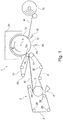
- the transfer of the fibrous web W to the Yankee drying cylinder 12 is made in a non-dewatering transfer nip TN that is formed between the Yankee drying cylinder 12 and a shoe roll 14.
- the shoe roll 14 comprises a shoe 15 that is arranged to act against the Yankee drying cylinder 12.
- the shoe roll 14 further comprises a rotatable flexible jacket 16 that is arranged to run in a loop around the shoe 15.
- a carrier fabric 10 loops the shoe roll 14 (i.e., the carrier fabric runs in a loop/forms a loop and the shoe roll 14 is located inside the loop formed by the carrier fabric 10) and the carrier fabric 10 has at least one side that is textured and is arranged to contact the fibrous web W such that a three-dimensional pattern is imprinted into the fibrous web W.
- the three-dimensional pattern may in particular be imprinted into the fibrous web W in the transfer nip TN but imprinting may optionally also be carried out in a nip preceding the transfer nip TN.
- the carrier fabric is a fabric that does not absorb water and the textured side of the carrier fabric has land areas separated from each other by open areas. The open areas can be depressions in the carrier fabric or through-holes in the carrier fabric.
- the shoe 15 of the shoe roll 14 is a shoe that is deformable such that it can adapt to the cylindrical outer surface 13 of the Yankee drying cylinder 12.
- a deformable shoe 15 may be made of an elastic material such as rubber or a material that has properties similar to rubber.
- a carrier fabric 10 may be an open wire intended for use in a through air drying (TAD) machine.
- TAD through air drying
- the carrier fabric 10 may be such a fabric.
- the carrier fabric 10 has land areas 29 formed by solid material and void areas 30 formed by through-holes in the wire. When the carrier fabric 10 is pressed against the Yankee drying cylinder 12 in the transfer nip TN, only the land areas 29 will be able to receive the force of the linear load in the transfer nip TN, the void areas 30 cannot carry any load.
- the pressure in the transfer nip will therefore be distributed over the land areas 29 that are in the transfer nip TN. If the pressure acting on the land areas 29 is too high, the land areas may be pressed through the fibrous web W and into the layer of coating and this must be avoided.
- the peak pressure as defined by the force of the linear load divided by the effective area of the carrier fabric 9 (i.e. the land areas 29) must therefore be controlled such that it remains within predetermined limits.
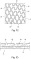
- Figure 12 and to Figure 13 show a carrier fabric 10 that has a base layer 40 which will not contact the fibrous web W.
- the base layer 40 may be permeable to air but may optionally also be impermeable to air.
- a textured side of the carrier fabric 10 has land areas 29 and open areas 30.
- the peak pressure as defined by the force of the linear load divided by the effective area of the carrier fabric 9 i.e. the land areas 29
- the peak pressure must therefore be controlled such that it remains within predetermined limits.
- Figure 11 and Figure 12 and 13 are only examples of how a structured/textured carrier fabric 10 may be designed and that the carrier fabric 10 may take many other different forms.
- the land areas 29 of that surface of the carrier fabric 10 that faces the fibrous web W may constitute 15 % - 90% of the total surface area facing the fibrous web W.
- the three-dimensional pattern can be imprinted into the fibrous web, for example, as the fibrous web W passes through the transfer nip TN together with the carrier fabric 10 and possibly also in a nip formed between the shoe roll 14 and another roll 17 (which would require that the shoe roll 14 has a shoe facing the roll 17 in Figure 1 ).
- the roll 17 may be a roll forming a nip with the shoe roll 14 but it may also be merely a guide roll that does not form any nip with the shoe roll 14.
- the inventive method comprises forming the transfer nip TN between the shoe 15 and the cylindrical outer surface 13 of the Yankee drying cylinder 12.
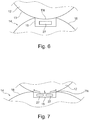
- the length L of the transfer nip TN in the circumferential direction of the Yankee drying cylinder 12 (for the length L, see Figure 7 ) is in the range of 30 mm - 100 mm, preferably 50 mm - 100 mm.
- the linear load in the transfer nip TN may be in the range of 35 kN/m - 120 kN/m.
- the pressure in the transfer nip TN should reach a certain level to pressure level.
- the structured/textured carrier fabric 10 is facing the fibrous web W in the transfer nip TN. If the peak pressure in the transfer nip TN becomes too high, the pressure from the land areas of the carrier fabric may go through the fibrous web and, in the worst case, also through the layer of chemical coating that has been applied by the spraying device 28 and to the outer surface 13 of the Yankee drying cylinder 12. This can be detrimental both to the fibrous web W and to the web transfer in the transfer nip TN.
- the carrier fabric is a fabric that has a structured/textured surface facing the fibrous web W
- the pressure acting on the carrier fabric will be distributed over the land areas 29 of the carrier fabric 10 while the open areas will be incapable of taking any of the pressure resulting from the linear load in the transfer nip, at least not to any significant extent.
- the peak pressure in the transfer nip TN should be kept in the range of 2 MPa - 8MPa and preferably 4 MPa - 8 MPa.
- the pressure in the transfer nip should be understood as being the force of the linear load divided by the sum of the land areas 29 that are in the transfer nip TN at a given moment (and faces the web W), i.e. the total land area of the carrier fabric 10 that is actually in the transfer nip TN in a given moment. If the pressure in the transfer nip is calculated without taking effective area (land area) into account, the pressure would simply be the total area of the carrier fabric facing the fibrous web W.
- the inventors have found that it is necessary to compensate for the fact that the available land area is less than 100 %. For example, let's assume that the actual land area (the sum of the land areas divided by total carrier fabric area) is only 50% and that, if no compensation is made for actual land area, the average pressure in a specific case is 3 MPa and the peak pressure 7 MPa. If the actual land area is taken into account, the average pressure will be 6 MPa and the peak pressure will be 14 MPa. The inventors have found that, when the peak pressure (as compensated for actual land area) is in the range of 2 MPa - 8 MPa, the web transfer to the outer surface 13 of the Yankee drying cylinder 12 will be reliable and the risk that the land areas 29 will penetrate too far is eliminated or at least significantly reduced. It should be understood that, "the total land area" in the transfer nip refers to the land area of that surface of the carrier fabric 10 that faces the fibrous web.
- the pressure curve i.e. the distribution of pressure in the transfer nip
- the pressure curve may be such that the peak pressure in the transfer nip TN does not exceed the average pressure in the transfer nip TN by more than 75% and preferably not by more than 60 %.
- the inventors have found that such a relatively even pressure distribution tends reduce damage to the fibrous web W, in particular damage to the pattern imprinted into the fibrous web W.
- the shoe 15 is a deformable shoe, this entails the advantage that the shoe 15 can adapt to different profiles of the Yankee drying cylinder 12 and to variations in the cross machined direction of the diameter of the Yankee drying cylinder 12 and this improves the transfer function.
- the pressure profile is normally not symmetrical but instead devised such that the pressure rises towards a pressure peak near the end of the nip.
- the peak pressure in the nip is usually considerably higher than the average pressure.
- the inventors of the present invention have now found that, when the peak pressure in a non-dewatering transfer nip is much higher than the average pressure in the transfer nip, this tends to result in damage to the fibrous web, particularly in the fibrous web is textured. Therefore, the inventors have also found that, preferably, the peak pressure in the transfer nip TN should not exceed average pressure by more than 75 % and preferably not by more than 60 %. Even more preferred, the peak pressure in the transfer nip TN does not exceed the average pressure in the transfer nip TN by more than 50 %.
- the newly formed fibrous web W is carried on the forming fabric 4 to a nip between a counter roll 17 and a shoe roll 14.
- a carrier fabric 10 that may be a belt passes through the nip and picks the fibrous web W from the forming fabric 4 and transfers the web W to the cylindrical outer surface 13 of the Yankee drying cylinder 12.
- the transfer of the web W to the Yankee cylindrical outer surface 13 of the Yankee drying cylinder 12 takes place in a transfer nip TN.
- the counter roll 17 is optional.
- the roll 17 in Figure 1 does not necessarily form a nip with the roll 14 but could be simply a guide roll.
- the carrier fabric 10 may in particular be a textured/structured belt, i.e. a belt that contacts the fibrous web with a textured/structured surface such that it capable of imprinting a three-dimensional structure into the fibrous web.
- the newly formed fibrous web W could be transferred from a forming fabric 3,4 to a textured fabric in a rush transfer arrangement, i.e. an arrangement where the fibrous web is "wet creped" by means of a speed difference between the fabrics and in which the fibrous web is subsequently transferred to the cylindrical outer surface 13 of the Yankee drying cylinder 12.
- FIG. 2 One variation of the layout of Figure 1 is shown in Figure 2 .
- the fibrous web W is travelling sandwiched between a forming fabric 4 that may be a water-absorbing felt and a carrier fabric 10 that may be a wire that is permeable to air.
- a suction device such as a suction box 31 (or a suction roll) may be arranged inside the loop of the carrier fabric 10 to ensure that the fibrous web follows the carrier fabric 10 and not the forming fabric 4.
- the suction device may be placed in the area opposite the guide roll 17.
- the carrier fabric 10 is made to wrap the shoe roll 14 and the wrap angle may be in the range of, for example, 45° - 180°. If the carrier fabric 10 that loops the shoe roll 14 also wraps the shoe roll 14 for more than 45°, this entails the advantage that the path of the carrier fabric 10 can be very precisely defined.
- FIG 3 an embodiment is shown that differs from that of Figure 2 in that the carrier fabric 10 is separated from the forming fabric 4 before the forming fabric 4 has reached the guide roll 17.
- a suction roll 32 placed inside the loop of the carrier fabric 10 ensures that the web W follows the carrier fabric 10 and not the forming fabric 4.
- the carrier fabric 10 that loops the shoe roll 14 hardly wraps the shoe roll 14 at all except when the carrier fabric 10 passes through the transfer nip TN.
- the suction roll 32 serves as a guide roll that guides the carrier fabric 10 to the transfer nip TN.
- the reference numerals 26 in Figure 3 indicate guide rolls.
- the carrier fabric 10 that loops the shoe roll 14 may thus be guided through the transfer nip TN in such a way that it wraps the shoe roll 14 only as it passes through the transfer nip TN.
- Such embodiments entail the advantage that a greater part of the shoe roll 14 becomes available for cleaning operations if cleaning operations are judged necessary (for example by sprinkling water on the jacket 6 of the shoe roll 14 to remove dirt).
- the shoe roll 14 has a shoe 15 that is deformable such that it can adapt to the cylindrical outer surface 13 of the Yankee drying cylinder 12 and the shoe roll 14 has a flexible jacket 6.
- the flexible jacket 6 may be made of polyurethane or a material that comprises polyurethane or has properties similar to polyurethane.
- the shoe roll 14 may optionally be designed as disclosed in US patent No. 7,527,708 but other designs are conceivable as long as the shoe can be pressed against the Yankee drying cylinder and deform to adapt to the outer shape of the Yankee drying cylinder.
- the shoe roll 14 could be designed as disclosed in EP 2085513 .
- the shoe 15 is a shoe made of an elastically deformable material and has one or several internal cavities 27 that can be filled with a pressurized fluid such that the shoe expands 15 such that the transfer nip TN can be closed.
- the shoe 15 may have two or more cavities that can be filled with a pressurized fluid.
- the fibrous web W is preferably brought into contact with a carrier fabric 10 that is a structured/textured fabric such that a three-dimensional pattern is imprinted into the fibrous web W.
- the carrier fabric 10 that passes through the transfer nip TN may be a textured/structured belt that has at least one side that is textured and faces the fibrous web W and imprints a three-dimensional pattern into the surface of the fibrous web W.
- the carrier fabric 10 may be an impermeable or substantially impermeable textured belt.
- it could be a structured/textured belt as disclosed in US patent No. 6,547,924 such that the bulk of the fibrous web is improved when the carrier fabric 10 imparts a three-dimensional structure to the fibrous web as the carrier fabric 10 passes together with the fibrous web W through the transfer nip TN and/or a nip with a counter roll 17.
- the Yankee drying cylinder 12 is the first drying cylinder on which the fibrous web W is dried.
- a suitable linear load in the transfer nip TN may be in the range of 65 kN/m - 95 kN/m, preferably 70 kN/m - 90 kN/m.
- the fibrous web W can be creped off from the cylindrical surface 13 of the Yankee drying cylinder 12 by a doctor 18 and be sent forward to a reel-up 19.
- the reel-up 19 which is only schematically indicated may be any reel-up suitable for a tissue web. For example, it could be a reel-up of the kind disclosed in US patent No. 5,845,868 or US patent No. 5,375,790 .
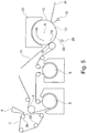
- the fibrous web W is first dried on at least one through-air drying cylinder 8 (or on two or more through-air drying cylinders 8, 9) and subsequently transferred to the Yankee drying cylinder 12.
- the fibrous web W will then be brought into contact with a carrier fabric 10 in the shape of a TAD wire that is foraminous (permeable to air) and which has a very high capacity for imparting a three-dimensional structure to the fibrous web W.
- the land area 29 of the carrier fabric 10 i.e.
- the surface area over which the linear load is distributed in the transfer nip TN can be quite small, for example 15% - 20% of the total area of the side of the carrier fabric that faces the fibrous web W.
- the inventors have found that the linear load in the transfer nip TN should be correspondingly lower that if the land area constitutes a greater part of the surface area of the carrier fabric.
- a linear load in the range of 35 kN/m - 45 kN/m may be used although other linear loads may optionally be used.
- the carrier fabric may be a TAD wire that has a total land area 29 that constitutes 22 % of the total carrier fabric surface facing the fibrous web.
- the length of the transfer nip may be 41 mm and the linear load 45 kN/m.
- the peak pressure acting on the actual land area in the transfer nip may be about 5 MPa (also dependent on the pressure profile).
- the pressure is commonly distributed such that the pressure builds up gradually to a sharp maximum at the end of the nip.
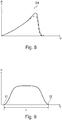
- a pressure curve is illustrated in Figure 8 where the maximum pressure is reached at a pressure peak 24.
- the maximum pressure is considerably higher than the average pressure.
- the inventors of the present invention have discovered that, in a transfer nip against a Yankee drying cylinder, such a pressure distribution may cause damage to the fibrous web W and that this is especially the case when the fibrous web W has been subjected to texturing by a textured/structured fabric.
- the three-dimensional pattern imparted to the fibrous web may easily become damaged. Therefore, it is preferred that the pressure distribution should instead be more even.
- Figure 9 shows a pressure curve in which the pressure is more evenly distributed between an entry point 21 into the transfer nip TN and an exit point 22 (In Figure 8, Figure 9 and Figure 10 , "P" represents pressure and “D” represents distance in the nip, i.e. the machine direction of the nip).
- P represents pressure
- D represents distance in the nip, i.e. the machine direction of the nip.
- the inventors have found that a pressure distribution according to Figure 9 results in less damage to the three-dimensional pattern of the fibrous web than a pressure distribution according to Figure 8 .
- the width of the machine (as defined by, for example, the width of the forming fabrics 3, 4) may be, for example, in the range of 2 m - 8 m and typical values could often be in the range of 3 m - 6 m.
- the machine may be running at a speed in the range of 1400 m/minute - 2000 m/minute but both higher and lower speeds are conceivable.
- the speed may often be in the range of 1500 m/minute to 1900 m/minute but the general trend is towards higher speeds and, within some years, the present invention may conceivably be operated at speeds up to 2500 m/minute or even higher speeds.
- Both surfaces of the carrier fabric 10 may optionally be structured/textured, in particular if the carrier fabric 10 is an open wire such as a TAD wire.
Landscapes
- Paper (AREA)
- Sanitary Thin Papers (AREA)
Claims (8)
- Verfahren zum Herstellen von Tissuepapier, in dem eine faserige Bahn (W) in einem Formgebungsabschnitt (2) gebildet wird und zu einem Yankee-Trocknungszylinder (12) in einem nicht-entwässernden Transferspalt (TN), der zwischen dem Yankee-Trocknungszylinder (12) und einer Schuhrolle (14) gebildet wird, transferiert wird, wobei der Yankee-Trocknungszylinder (12) eine zylindrische äußere Oberfläche (13) aufweist und angeordnet ist, um um eine Rotationsachse (A) drehbar zu sein, wobei die Schuhrolle (14) einen Schuh (15) umfasst, der angeordnet ist, gegen den Yankee-Trocknungszylinder (12) zu wirken, und die Schuhrolle (14) ferner einen drehbaren flexiblen Mantel (16) umfasst, der angeordnet ist, in einer Schleife um den Schuh (15) zu laufen, wobei in dem Verfahren ein Trägergewebe (10) in einer Schlaufe um die Schuhrolle (14) läuft und der faserigen Bahn (W) in den Transferspalt (TN) folgt, wobei das Trägergewebe (10) eine strukturierte Oberfläche aufweist, die der faserigen Bahn (W) zugewandt ist, so dass ein dreidimensionales Muster in die faserige Bahn (W) durch das Trägergewebe (10) eingeprägt werden kann und die strukturierte Oberfläche des Trägergewebes (10) Landbereiche (29) und offene Bereiche (30) aufweist und wobei das Verfahren Bilden des Transferspaltes (TN) zwischen dem Schuh (15) und der zylindrischen äußeren Oberfläche (13) des Yankee-Trocknungszylinders (12) umfasst und wobei die Länge (L) des Transferspaltes (TN) in der Umfangsrichtung des Yankee-Trocknungszylinders (12) in dem Bereich von 30 mm - 100 mm liegt und wobei das Verfahren Aufbringen einer chemischen Beschichtung auf der zylindrischen äußeren Oberfläche (13) des Yankee-Trocknungszylinders (12) und Kreppen der faserigen Bahn (W) von der zylindrischen äußeren Oberfläche (13) des Yankee-Trocknungszylinders (12) umfasst, gekennzeichnet dadurch, dass die Landbereiche (29) der strukturierten Oberfläche des Trägergewebes (10) 15 % - 90 % des gesamten Oberflächenbereichs der Seite des Trägergewebes (10) ausmacht, der der faserigen Bahn (W) zugewandt ist, und dadurch, dass die lineare Last in dem Transferspalt ausgewählt wird, so dass der Spitzendruck in dem Transferspalt (TN) in dem Bereich von 2 MPa - 8 MPa liegt, wenn der Druck in dem Transferspalt (TN) definiert wird als die Kraft der linearen Last in dem Transferspalt (TN) geteilt durch die Summe der Landbereiche (29) des Teils des Trägergewebes (10), der sich in dem Transferspalt (TN) in einem bestimmten Moment befindet.
- Verfahren nach Anspruch 1, wobei der Spitzendruck in dem Transferspalt (TN) den durchschnittlichen Druck in dem Transferspalt (TN) nicht um mehr als 75 % und bevorzugt nicht um mehr als 60 % überschreitet.
- Verfahren nach Anspruch 1, wobei der Spitzendruck in dem Transferspalt (TN) den durchschnittlichen Druck in dem Transferspalt (TN) nicht um mehr als 50% überschreitet.
- Verfahren nach einem der Ansprüche 1-3, wobei die faserige Bahn (W) zuerst auf wenigstens einem Durchluft-Trocknungszylinder (8, 9) getrocknet wird und anschließend zu dem Yankee-Trocknungszylinder (12) transferiert wird und wobei die lineare Last in dem Transferspalt (TN) in dem Bereich von 35 kN/m - 45 kN/m liegt.
- Verfahren nach einem der Ansprüche 1-3, wobei der Yankee-Trocknungszylinder (12) der erste Trocknungszylinder ist, auf dem die faserige Bahn (W) getrocknet wird, und wobei die lineare Last in dem Transferspalt (TN) in dem Bereich von 65 kN/m - 95 kN/m, bevorzugt 70 kN/m - 90 kN/m liegt.
- Verfahren nach einem der Ansprüche 1-3, wobei der Druck in dem Transferspalt (TN) so verteilt ist, dass der Druck einer Druckkurve von einem Eintrittspunkt (21) des Transferspaltes zu einem Austrittspunkt (22) des Transferspaltes folgt und wobei die Druckkurve einen Sattelpunkt (23) aufweist, der sich zwischen zwei Punkten (24, 25) befindet wo der Druck höher ist als in dem Sattelpunkt (23).
- Verfahren nach einem der Ansprüche 1-5, wobei das Tissue-Papier ein Basisgewicht in dem Bereich von 12 g/m2 - 30 g/m2 aufweist, wenn es den Yankee-Trocknungszylinder (12) verlässt.
- Verfahren nach Anspruch 1, wobei der Schuh (15) der Schuhrolle (14) ein verformbarer Schuh (15) ist, der sich an die Form der zylindrischen äußeren Oberfläche (13) des Yankee-Trocknungszylinders (12) anpassen kann.
Applications Claiming Priority (2)
| Application Number | Priority Date | Filing Date | Title |
|---|---|---|---|
| SE1651680A SE540185C2 (en) | 2016-12-19 | 2016-12-19 | A method for making tissue paper |
| PCT/EP2017/082369 WO2018114467A1 (en) | 2016-12-19 | 2017-12-12 | A method for making tissue paper |
Publications (2)
| Publication Number | Publication Date |
|---|---|
| EP3555362A1 EP3555362A1 (de) | 2019-10-23 |
| EP3555362B1 true EP3555362B1 (de) | 2020-10-07 |
Family
ID=60812048
Family Applications (1)
| Application Number | Title | Priority Date | Filing Date |
|---|---|---|---|
| EP17821526.5A Active EP3555362B1 (de) | 2016-12-19 | 2017-12-12 | Verfahren zur herstellung von tissuepapier |
Country Status (7)
| Country | Link |
|---|---|
| US (1) | US10808359B2 (de) |
| EP (1) | EP3555362B1 (de) |
| JP (1) | JP2020502384A (de) |
| CN (1) | CN110100058B (de) |
| BR (1) | BR112019012143B1 (de) |
| SE (1) | SE540185C2 (de) |
| WO (1) | WO2018114467A1 (de) |
Families Citing this family (8)
| Publication number | Priority date | Publication date | Assignee | Title |
|---|---|---|---|---|
| SE540185C2 (en) * | 2016-12-19 | 2018-04-24 | Valmet Oy | A method for making tissue paper |
| SE542214C2 (en) * | 2018-10-12 | 2020-03-10 | Valmet Oy | A tissue paper making machine and a method of operating a tissue paper making machine |
| SE1950671A1 (en) * | 2019-06-05 | 2020-12-06 | Valmet Oy | A machine and a method for making tissue paper |
| CA3081992A1 (en) | 2019-06-06 | 2020-12-06 | Structured I, Llc | Papermaking machine that utilizes only a structured fabric in the forming of paper |
| SE544018C2 (en) | 2020-01-09 | 2021-11-02 | Valmet Oy | A tissue paper making machine |
| CN113684719A (zh) * | 2021-07-26 | 2021-11-23 | 白城福佳科技有限公司 | 一种射流气浮干燥生产卫生纸的设备及其方法 |
| SE2430295A1 (en) * | 2024-05-28 | 2025-11-29 | Valmet Oy | Tissue paper machine comprising an extended nip press forming a transfer nip with variable linear load |
| SE547824C2 (en) * | 2024-05-28 | 2025-12-02 | Valmet Oy | Paper machine arranged to form a short extended non-dewatering transfer nip |
Family Cites Families (32)
| Publication number | Priority date | Publication date | Assignee | Title |
|---|---|---|---|---|
| SE469071B (sv) | 1991-09-18 | 1993-05-10 | Valmet Karlstad Ab | Rullstol med centrumdriven upprullningsvals |
| US5441604A (en) * | 1994-02-17 | 1995-08-15 | Beloit Technologies, Inc. | Extended nip press apparatus |
| CN1242811A (zh) * | 1996-11-14 | 2000-01-26 | 普罗克特和甘保尔公司 | 干燥蓬松且平滑的纸幅的方法 |
| US5845868A (en) | 1997-07-03 | 1998-12-08 | Valmet-Karlstad Ab | Apparatus and method for winding paper |
| US6547924B2 (en) * | 1998-03-20 | 2003-04-15 | Metso Paper Karlstad Ab | Paper machine for and method of manufacturing textured soft paper |
| US6790315B2 (en) * | 1999-06-17 | 2004-09-14 | Metso Paper Karlstad Ab | Drying section and method for drying a paper web |
| SE516663C2 (sv) * | 1999-06-17 | 2002-02-12 | Metso Paper Karlstad Ab | Torkparti i en maskin för tillverkning av en kontinuerlig tissuepappersbana samt metod för torkning av en kontinuerlig |
| US6398916B1 (en) | 1999-12-16 | 2002-06-04 | Valmet Karlstad Ab | Simplified through-air drying paper making machine having a twin wire forming section |
| DE10040681C1 (de) * | 2000-08-19 | 2001-09-13 | Autoliv Dev | Kraftfahrzeug mit einer an die Innenausstattung angebundenen Gassackeinrichtung |
| US7597778B2 (en) * | 2002-04-25 | 2009-10-06 | Voith Paper Patent Gmbh | Method for the production of a web of tissue material |
| DE10218509A1 (de) * | 2002-04-25 | 2003-11-06 | Voith Paper Patent Gmbh | Verfahren zur Herstellung einer Tissuebahn |
| US7789995B2 (en) * | 2002-10-07 | 2010-09-07 | Georgia-Pacific Consumer Products, LP | Fabric crepe/draw process for producing absorbent sheet |
| US7527708B2 (en) | 2003-10-21 | 2009-05-05 | Metso Paper Karlstad Ab | Support body, holding device therefor, apparatus with said body for treatment of a web, and methods of forming an extended nip in the apparatus and controlling load in the nip |
| US7387706B2 (en) * | 2004-01-30 | 2008-06-17 | Voith Paper Patent Gmbh | Process of material web formation on a structured fabric in a paper machine |
| US7493012B2 (en) | 2004-04-20 | 2009-02-17 | Zootech Limited | Compatibility testing |
| JP4779564B2 (ja) * | 2005-10-18 | 2011-09-28 | 王子製紙株式会社 | 抄紙機のシュープレス装置及び紙の製造方法 |
| FI122859B (fi) * | 2006-05-09 | 2012-08-15 | Metso Paper Inc | Menetelmä ja laitteisto paperin/kartongin pintakäsittelemiseksi |
| KR101483167B1 (ko) | 2006-10-27 | 2015-01-16 | 발멧 에이비 | 제지 장치의 불침투성 이송 벨트를 구비한 장치와, 관련 방법 |
| BRPI0721415B1 (pt) | 2007-03-01 | 2020-11-10 | Toscotec S.P.A. | cilindro yankee feito de aço, que inclui uma carcaça cilíndrica unida a duas extremidades |
| ATE528442T1 (de) * | 2007-08-21 | 2011-10-15 | Metso Paper Inc | Pressvorrichtung für eine papier- oder kartonmaschine zur entfernung von flüssigkeiten aus einer faserstoffbahn durch pressen sowie verfahren zur behandlung einer faserstoffbahn in einer papier- oder kartonmaschine |
| SE531891C2 (sv) * | 2007-11-20 | 2009-09-01 | Metso Paper Karlstad Ab | Struktureringsbeklädnad och förfarande för framställning av en tissuepappersbana |
| DE102008000199A1 (de) | 2008-01-31 | 2009-08-06 | Voith Patent Gmbh | Anpresseinheit |
| SE533043C2 (sv) * | 2008-09-17 | 2010-06-15 | Metso Paper Karlstad Ab | Tissuepappersmaskin |
| US8673118B2 (en) * | 2011-02-18 | 2014-03-18 | Valmet Aktiebolag | Press device with an extended nip, a paper making machine and a method of operating a press device |
| SE536201C2 (sv) | 2011-07-28 | 2013-06-25 | Metso Paper Sweden Ab | En maskin för framställning av Tissue-papper och en metod att köra en sådan maskin |
| EP2910679B1 (de) * | 2011-12-07 | 2017-05-17 | Valmet Aktiebolag | Eine verlängerte anpresswalze einer papierherstellungsmaschine und verfahren zur herstellung von tissuepapier |
| BR112014025803B1 (pt) * | 2012-04-19 | 2021-09-08 | Valmet Aktiebolag | Rolo de aperto alongado, prensa de aperto alongada utilizando o rolo de aperto alongado, máquina de fabricação de papel e método de operar uma prensa de aperto alongada |
| RU2687640C2 (ru) * | 2014-09-25 | 2019-05-15 | Олбэни Интернешнл Корп. | Многослойная лента для крепирования и структурирования в процессе изготовления основанного на целлюлозе продукта |
| EP2963176B1 (de) | 2015-04-23 | 2017-03-15 | Valmet S.p.A. | Yankee-trockenhaubenanordnung, yankee-trockenzylinder mit einer yankee-trockenhaubenanordnung und verfahren zur trocknung einer faserbahn |
| SE540011C2 (en) * | 2015-05-19 | 2018-02-27 | Valmet Oy | A method of making a structured fibrous web and a creped fibrous web |
| SE1651555A1 (en) * | 2016-11-28 | 2018-02-13 | Valmet Oy | A forming section for forming a fibrous web, a papermaking machine comprising a forming section and a method of forming a fibrous web |
| SE540185C2 (en) * | 2016-12-19 | 2018-04-24 | Valmet Oy | A method for making tissue paper |
-
2016
- 2016-12-19 SE SE1651680A patent/SE540185C2/en unknown
-
2017
- 2017-12-12 WO PCT/EP2017/082369 patent/WO2018114467A1/en not_active Ceased
- 2017-12-12 US US16/471,316 patent/US10808359B2/en active Active
- 2017-12-12 CN CN201780078567.2A patent/CN110100058B/zh active Active
- 2017-12-12 JP JP2019532959A patent/JP2020502384A/ja active Pending
- 2017-12-12 EP EP17821526.5A patent/EP3555362B1/de active Active
- 2017-12-12 BR BR112019012143-9A patent/BR112019012143B1/pt active IP Right Grant
Non-Patent Citations (1)
| Title |
|---|
| None * |
Also Published As
| Publication number | Publication date |
|---|---|
| US20190316296A1 (en) | 2019-10-17 |
| BR112019012143B1 (pt) | 2023-02-07 |
| EP3555362A1 (de) | 2019-10-23 |
| US10808359B2 (en) | 2020-10-20 |
| SE1651680A1 (en) | 2018-04-24 |
| JP2020502384A (ja) | 2020-01-23 |
| WO2018114467A1 (en) | 2018-06-28 |
| CN110100058A (zh) | 2019-08-06 |
| SE540185C2 (en) | 2018-04-24 |
| CN110100058B (zh) | 2021-10-08 |
| BR112019012143A2 (pt) | 2019-11-05 |
Similar Documents
| Publication | Publication Date | Title |
|---|---|---|
| EP3555362B1 (de) | Verfahren zur herstellung von tissuepapier | |
| JP6181098B2 (ja) | 紙製造装置、延伸ニップロール及びティッシュペーパを製造するための方法 | |
| EP2227591B1 (de) | Strukturierende papiermaschinenbespannung und verfahren zur herstellung einer tissuepapierbahn | |
| EP2732096B1 (de) | Verfahren und maschine zur herstellung einer strukturierten faserbahn aus papier | |
| CN101432481B (zh) | 成型织物和/或棉纸模压带和/或atmos系统上采用的模压带 | |
| EP2737125B1 (de) | Papierherstellungsmaschine zur herstellung von tissuepapier und verfahren zum betrieb einer papiermaschine | |
| EP3864218B1 (de) | Tissuepapierherstellungsmaschine und verfahren zum betrieb einer tissuepapierherstellungsmaschine | |
| US6387218B1 (en) | Air press seal in paper-making machine | |
| WO2020246926A1 (en) | A machine and a method for making tissue paper | |
| WO2015171043A1 (en) | A shoe press and a machine for producing laminated paperboard |
Legal Events
| Date | Code | Title | Description |
|---|---|---|---|
| STAA | Information on the status of an ep patent application or granted ep patent |
Free format text: STATUS: UNKNOWN |
|
| STAA | Information on the status of an ep patent application or granted ep patent |
Free format text: STATUS: THE INTERNATIONAL PUBLICATION HAS BEEN MADE |
|
| PUAI | Public reference made under article 153(3) epc to a published international application that has entered the european phase |
Free format text: ORIGINAL CODE: 0009012 |
|
| STAA | Information on the status of an ep patent application or granted ep patent |
Free format text: STATUS: REQUEST FOR EXAMINATION WAS MADE |
|
| 17P | Request for examination filed |
Effective date: 20190619 |
|
| AK | Designated contracting states |
Kind code of ref document: A1 Designated state(s): AL AT BE BG CH CY CZ DE DK EE ES FI FR GB GR HR HU IE IS IT LI LT LU LV MC MK MT NL NO PL PT RO RS SE SI SK SM TR |
|
| AX | Request for extension of the european patent |
Extension state: BA ME |
|
| DAV | Request for validation of the european patent (deleted) | ||
| DAX | Request for extension of the european patent (deleted) | ||
| GRAP | Despatch of communication of intention to grant a patent |
Free format text: ORIGINAL CODE: EPIDOSNIGR1 |
|
| STAA | Information on the status of an ep patent application or granted ep patent |
Free format text: STATUS: GRANT OF PATENT IS INTENDED |
|
| INTG | Intention to grant announced |
Effective date: 20200528 |
|
| GRAS | Grant fee paid |
Free format text: ORIGINAL CODE: EPIDOSNIGR3 |
|
| GRAA | (expected) grant |
Free format text: ORIGINAL CODE: 0009210 |
|
| STAA | Information on the status of an ep patent application or granted ep patent |
Free format text: STATUS: THE PATENT HAS BEEN GRANTED |
|
| AK | Designated contracting states |
Kind code of ref document: B1 Designated state(s): AL AT BE BG CH CY CZ DE DK EE ES FI FR GB GR HR HU IE IS IT LI LT LU LV MC MK MT NL NO PL PT RO RS SE SI SK SM TR |
|
| REG | Reference to a national code |
Ref country code: GB Ref legal event code: FG4D |
|
| REG | Reference to a national code |
Ref country code: AT Ref legal event code: REF Ref document number: 1321265 Country of ref document: AT Kind code of ref document: T Effective date: 20201015 Ref country code: CH Ref legal event code: EP |
|
| REG | Reference to a national code |
Ref country code: IE Ref legal event code: FG4D |
|
| REG | Reference to a national code |
Ref country code: DE Ref legal event code: R096 Ref document number: 602017025190 Country of ref document: DE |
|
| REG | Reference to a national code |
Ref country code: NL Ref legal event code: MP Effective date: 20201007 |
|
| PG25 | Lapsed in a contracting state [announced via postgrant information from national office to epo] |
Ref country code: NO Free format text: LAPSE BECAUSE OF FAILURE TO SUBMIT A TRANSLATION OF THE DESCRIPTION OR TO PAY THE FEE WITHIN THE PRESCRIBED TIME-LIMIT Effective date: 20210107 Ref country code: GR Free format text: LAPSE BECAUSE OF FAILURE TO SUBMIT A TRANSLATION OF THE DESCRIPTION OR TO PAY THE FEE WITHIN THE PRESCRIBED TIME-LIMIT Effective date: 20210108 Ref country code: FI Free format text: LAPSE BECAUSE OF FAILURE TO SUBMIT A TRANSLATION OF THE DESCRIPTION OR TO PAY THE FEE WITHIN THE PRESCRIBED TIME-LIMIT Effective date: 20201007 Ref country code: PT Free format text: LAPSE BECAUSE OF FAILURE TO SUBMIT A TRANSLATION OF THE DESCRIPTION OR TO PAY THE FEE WITHIN THE PRESCRIBED TIME-LIMIT Effective date: 20210208 Ref country code: RS Free format text: LAPSE BECAUSE OF FAILURE TO SUBMIT A TRANSLATION OF THE DESCRIPTION OR TO PAY THE FEE WITHIN THE PRESCRIBED TIME-LIMIT Effective date: 20201007 |
|
| REG | Reference to a national code |
Ref country code: LT Ref legal event code: MG4D |
|
| PG25 | Lapsed in a contracting state [announced via postgrant information from national office to epo] |
Ref country code: ES Free format text: LAPSE BECAUSE OF FAILURE TO SUBMIT A TRANSLATION OF THE DESCRIPTION OR TO PAY THE FEE WITHIN THE PRESCRIBED TIME-LIMIT Effective date: 20201007 Ref country code: BG Free format text: LAPSE BECAUSE OF FAILURE TO SUBMIT A TRANSLATION OF THE DESCRIPTION OR TO PAY THE FEE WITHIN THE PRESCRIBED TIME-LIMIT Effective date: 20210107 Ref country code: IS Free format text: LAPSE BECAUSE OF FAILURE TO SUBMIT A TRANSLATION OF THE DESCRIPTION OR TO PAY THE FEE WITHIN THE PRESCRIBED TIME-LIMIT Effective date: 20210207 Ref country code: PL Free format text: LAPSE BECAUSE OF FAILURE TO SUBMIT A TRANSLATION OF THE DESCRIPTION OR TO PAY THE FEE WITHIN THE PRESCRIBED TIME-LIMIT Effective date: 20201007 Ref country code: LV Free format text: LAPSE BECAUSE OF FAILURE TO SUBMIT A TRANSLATION OF THE DESCRIPTION OR TO PAY THE FEE WITHIN THE PRESCRIBED TIME-LIMIT Effective date: 20201007 Ref country code: SE Free format text: LAPSE BECAUSE OF FAILURE TO SUBMIT A TRANSLATION OF THE DESCRIPTION OR TO PAY THE FEE WITHIN THE PRESCRIBED TIME-LIMIT Effective date: 20201007 |
|
| PG25 | Lapsed in a contracting state [announced via postgrant information from national office to epo] |
Ref country code: NL Free format text: LAPSE BECAUSE OF FAILURE TO SUBMIT A TRANSLATION OF THE DESCRIPTION OR TO PAY THE FEE WITHIN THE PRESCRIBED TIME-LIMIT Effective date: 20201007 Ref country code: HR Free format text: LAPSE BECAUSE OF FAILURE TO SUBMIT A TRANSLATION OF THE DESCRIPTION OR TO PAY THE FEE WITHIN THE PRESCRIBED TIME-LIMIT Effective date: 20201007 |
|
| REG | Reference to a national code |
Ref country code: DE Ref legal event code: R097 Ref document number: 602017025190 Country of ref document: DE |
|
| PG25 | Lapsed in a contracting state [announced via postgrant information from national office to epo] |
Ref country code: LT Free format text: LAPSE BECAUSE OF FAILURE TO SUBMIT A TRANSLATION OF THE DESCRIPTION OR TO PAY THE FEE WITHIN THE PRESCRIBED TIME-LIMIT Effective date: 20201007 Ref country code: CZ Free format text: LAPSE BECAUSE OF FAILURE TO SUBMIT A TRANSLATION OF THE DESCRIPTION OR TO PAY THE FEE WITHIN THE PRESCRIBED TIME-LIMIT Effective date: 20201007 Ref country code: EE Free format text: LAPSE BECAUSE OF FAILURE TO SUBMIT A TRANSLATION OF THE DESCRIPTION OR TO PAY THE FEE WITHIN THE PRESCRIBED TIME-LIMIT Effective date: 20201007 Ref country code: SM Free format text: LAPSE BECAUSE OF FAILURE TO SUBMIT A TRANSLATION OF THE DESCRIPTION OR TO PAY THE FEE WITHIN THE PRESCRIBED TIME-LIMIT Effective date: 20201007 Ref country code: RO Free format text: LAPSE BECAUSE OF FAILURE TO SUBMIT A TRANSLATION OF THE DESCRIPTION OR TO PAY THE FEE WITHIN THE PRESCRIBED TIME-LIMIT Effective date: 20201007 Ref country code: SK Free format text: LAPSE BECAUSE OF FAILURE TO SUBMIT A TRANSLATION OF THE DESCRIPTION OR TO PAY THE FEE WITHIN THE PRESCRIBED TIME-LIMIT Effective date: 20201007 |
|
| REG | Reference to a national code |
Ref country code: CH Ref legal event code: PL |
|
| PLBE | No opposition filed within time limit |
Free format text: ORIGINAL CODE: 0009261 |
|
| STAA | Information on the status of an ep patent application or granted ep patent |
Free format text: STATUS: NO OPPOSITION FILED WITHIN TIME LIMIT |
|
| PG25 | Lapsed in a contracting state [announced via postgrant information from national office to epo] |
Ref country code: DK Free format text: LAPSE BECAUSE OF FAILURE TO SUBMIT A TRANSLATION OF THE DESCRIPTION OR TO PAY THE FEE WITHIN THE PRESCRIBED TIME-LIMIT Effective date: 20201007 Ref country code: MC Free format text: LAPSE BECAUSE OF FAILURE TO SUBMIT A TRANSLATION OF THE DESCRIPTION OR TO PAY THE FEE WITHIN THE PRESCRIBED TIME-LIMIT Effective date: 20201007 |
|
| REG | Reference to a national code |
Ref country code: BE Ref legal event code: MM Effective date: 20201231 |
|
| 26N | No opposition filed |
Effective date: 20210708 |
|
| PG25 | Lapsed in a contracting state [announced via postgrant information from national office to epo] |
Ref country code: LU Free format text: LAPSE BECAUSE OF NON-PAYMENT OF DUE FEES Effective date: 20201212 Ref country code: AL Free format text: LAPSE BECAUSE OF FAILURE TO SUBMIT A TRANSLATION OF THE DESCRIPTION OR TO PAY THE FEE WITHIN THE PRESCRIBED TIME-LIMIT Effective date: 20201007 Ref country code: FR Free format text: LAPSE BECAUSE OF NON-PAYMENT OF DUE FEES Effective date: 20201231 Ref country code: IE Free format text: LAPSE BECAUSE OF NON-PAYMENT OF DUE FEES Effective date: 20201212 |
|
| PG25 | Lapsed in a contracting state [announced via postgrant information from national office to epo] |
Ref country code: CH Free format text: LAPSE BECAUSE OF NON-PAYMENT OF DUE FEES Effective date: 20201231 Ref country code: SI Free format text: LAPSE BECAUSE OF FAILURE TO SUBMIT A TRANSLATION OF THE DESCRIPTION OR TO PAY THE FEE WITHIN THE PRESCRIBED TIME-LIMIT Effective date: 20201007 Ref country code: LI Free format text: LAPSE BECAUSE OF NON-PAYMENT OF DUE FEES Effective date: 20201231 |
|
| REG | Reference to a national code |
Ref country code: AT Ref legal event code: UEP Ref document number: 1321265 Country of ref document: AT Kind code of ref document: T Effective date: 20201007 |
|
| PG25 | Lapsed in a contracting state [announced via postgrant information from national office to epo] |
Ref country code: IS Free format text: LAPSE BECAUSE OF FAILURE TO SUBMIT A TRANSLATION OF THE DESCRIPTION OR TO PAY THE FEE WITHIN THE PRESCRIBED TIME-LIMIT Effective date: 20210207 Ref country code: TR Free format text: LAPSE BECAUSE OF FAILURE TO SUBMIT A TRANSLATION OF THE DESCRIPTION OR TO PAY THE FEE WITHIN THE PRESCRIBED TIME-LIMIT Effective date: 20201007 Ref country code: MT Free format text: LAPSE BECAUSE OF FAILURE TO SUBMIT A TRANSLATION OF THE DESCRIPTION OR TO PAY THE FEE WITHIN THE PRESCRIBED TIME-LIMIT Effective date: 20201007 Ref country code: CY Free format text: LAPSE BECAUSE OF FAILURE TO SUBMIT A TRANSLATION OF THE DESCRIPTION OR TO PAY THE FEE WITHIN THE PRESCRIBED TIME-LIMIT Effective date: 20201007 |
|
| PG25 | Lapsed in a contracting state [announced via postgrant information from national office to epo] |
Ref country code: MK Free format text: LAPSE BECAUSE OF FAILURE TO SUBMIT A TRANSLATION OF THE DESCRIPTION OR TO PAY THE FEE WITHIN THE PRESCRIBED TIME-LIMIT Effective date: 20201007 |
|
| PG25 | Lapsed in a contracting state [announced via postgrant information from national office to epo] |
Ref country code: BE Free format text: LAPSE BECAUSE OF NON-PAYMENT OF DUE FEES Effective date: 20201231 |
|
| GBPC | Gb: european patent ceased through non-payment of renewal fee |
Effective date: 20211212 |
|
| PG25 | Lapsed in a contracting state [announced via postgrant information from national office to epo] |
Ref country code: GB Free format text: LAPSE BECAUSE OF NON-PAYMENT OF DUE FEES Effective date: 20211212 |
|
| P01 | Opt-out of the competence of the unified patent court (upc) registered |
Effective date: 20230513 |
|
| PGFP | Annual fee paid to national office [announced via postgrant information from national office to epo] |
Ref country code: AT Payment date: 20251219 Year of fee payment: 9 |
|
| PGFP | Annual fee paid to national office [announced via postgrant information from national office to epo] |
Ref country code: IT Payment date: 20251212 Year of fee payment: 9 |
|
| PGFP | Annual fee paid to national office [announced via postgrant information from national office to epo] |
Ref country code: DE Payment date: 20251222 Year of fee payment: 9 |