EP3554892B1 - Fold-in outside display mirror - Google Patents
Fold-in outside display mirror Download PDFInfo
- Publication number
- EP3554892B1 EP3554892B1 EP17881543.7A EP17881543A EP3554892B1 EP 3554892 B1 EP3554892 B1 EP 3554892B1 EP 17881543 A EP17881543 A EP 17881543A EP 3554892 B1 EP3554892 B1 EP 3554892B1
- Authority
- EP
- European Patent Office
- Prior art keywords
- housing
- rearview assembly
- external rearview
- electro
- imager
- Prior art date
- Legal status (The legal status is an assumption and is not a legal conclusion. Google has not performed a legal analysis and makes no representation as to the accuracy of the status listed.)
- Active
Links
- 230000002093 peripheral effect Effects 0.000 claims description 6
- 238000004891 communication Methods 0.000 claims description 3
- 230000003287 optical effect Effects 0.000 claims description 2
- 238000000034 method Methods 0.000 description 14
- 239000000463 material Substances 0.000 description 10
- 239000000758 substrate Substances 0.000 description 9
- 230000008569 process Effects 0.000 description 8
- 238000012986 modification Methods 0.000 description 4
- 230000004048 modification Effects 0.000 description 4
- 239000011800 void material Substances 0.000 description 4
- 230000008901 benefit Effects 0.000 description 3
- 239000004020 conductor Substances 0.000 description 3
- 238000010276 construction Methods 0.000 description 3
- 239000000853 adhesive Substances 0.000 description 2
- 230000001070 adhesive effect Effects 0.000 description 2
- 239000002390 adhesive tape Substances 0.000 description 2
- 239000003086 colorant Substances 0.000 description 2
- BQCADISMDOOEFD-UHFFFAOYSA-N Silver Chemical compound [Ag] BQCADISMDOOEFD-UHFFFAOYSA-N 0.000 description 1
- 230000004913 activation Effects 0.000 description 1
- 239000002313 adhesive film Substances 0.000 description 1
- 230000000712 assembly Effects 0.000 description 1
- 238000000429 assembly Methods 0.000 description 1
- 230000008859 change Effects 0.000 description 1
- 230000008878 coupling Effects 0.000 description 1
- 238000010168 coupling process Methods 0.000 description 1
- 238000005859 coupling reaction Methods 0.000 description 1
- 238000013461 design Methods 0.000 description 1
- 239000006260 foam Substances 0.000 description 1
- 239000000446 fuel Substances 0.000 description 1
- 239000011521 glass Substances 0.000 description 1
- 230000005484 gravity Effects 0.000 description 1
- 238000009434 installation Methods 0.000 description 1
- 239000007788 liquid Substances 0.000 description 1
- 230000013011 mating Effects 0.000 description 1
- 230000007246 mechanism Effects 0.000 description 1
- 239000002184 metal Substances 0.000 description 1
- 229910052751 metal Inorganic materials 0.000 description 1
- 229910001092 metal group alloy Inorganic materials 0.000 description 1
- 239000003595 mist Substances 0.000 description 1
- 239000002991 molded plastic Substances 0.000 description 1
- 238000012552 review Methods 0.000 description 1
- 238000007789 sealing Methods 0.000 description 1
- 229910052709 silver Inorganic materials 0.000 description 1
- 239000004332 silver Substances 0.000 description 1
- 238000006467 substitution reaction Methods 0.000 description 1
- 238000005406 washing Methods 0.000 description 1
Images


Classifications
-
- B—PERFORMING OPERATIONS; TRANSPORTING
- B60—VEHICLES IN GENERAL
- B60R—VEHICLES, VEHICLE FITTINGS, OR VEHICLE PARTS, NOT OTHERWISE PROVIDED FOR
- B60R1/00—Optical viewing arrangements; Real-time viewing arrangements for drivers or passengers using optical image capturing systems, e.g. cameras or video systems specially adapted for use in or on vehicles
- B60R1/12—Mirror assemblies combined with other articles, e.g. clocks
-
- B—PERFORMING OPERATIONS; TRANSPORTING
- B60—VEHICLES IN GENERAL
- B60R—VEHICLES, VEHICLE FITTINGS, OR VEHICLE PARTS, NOT OTHERWISE PROVIDED FOR
- B60R1/00—Optical viewing arrangements; Real-time viewing arrangements for drivers or passengers using optical image capturing systems, e.g. cameras or video systems specially adapted for use in or on vehicles
- B60R1/02—Rear-view mirror arrangements
- B60R1/06—Rear-view mirror arrangements mounted on vehicle exterior
- B60R1/062—Rear-view mirror arrangements mounted on vehicle exterior with remote control for adjusting position
- B60R1/07—Rear-view mirror arrangements mounted on vehicle exterior with remote control for adjusting position by electrically powered actuators
- B60R1/074—Rear-view mirror arrangements mounted on vehicle exterior with remote control for adjusting position by electrically powered actuators for retracting the mirror arrangements to a non-use position alongside the vehicle
-
- B—PERFORMING OPERATIONS; TRANSPORTING
- B60—VEHICLES IN GENERAL
- B60R—VEHICLES, VEHICLE FITTINGS, OR VEHICLE PARTS, NOT OTHERWISE PROVIDED FOR
- B60R1/00—Optical viewing arrangements; Real-time viewing arrangements for drivers or passengers using optical image capturing systems, e.g. cameras or video systems specially adapted for use in or on vehicles
- B60R1/02—Rear-view mirror arrangements
- B60R1/08—Rear-view mirror arrangements involving special optical features, e.g. avoiding blind spots, e.g. convex mirrors; Side-by-side associations of rear-view and other mirrors
-
- B—PERFORMING OPERATIONS; TRANSPORTING
- B60—VEHICLES IN GENERAL
- B60R—VEHICLES, VEHICLE FITTINGS, OR VEHICLE PARTS, NOT OTHERWISE PROVIDED FOR
- B60R1/00—Optical viewing arrangements; Real-time viewing arrangements for drivers or passengers using optical image capturing systems, e.g. cameras or video systems specially adapted for use in or on vehicles
- B60R1/20—Real-time viewing arrangements for drivers or passengers using optical image capturing systems, e.g. cameras or video systems specially adapted for use in or on vehicles
- B60R1/22—Real-time viewing arrangements for drivers or passengers using optical image capturing systems, e.g. cameras or video systems specially adapted for use in or on vehicles for viewing an area outside the vehicle, e.g. the exterior of the vehicle
- B60R1/23—Real-time viewing arrangements for drivers or passengers using optical image capturing systems, e.g. cameras or video systems specially adapted for use in or on vehicles for viewing an area outside the vehicle, e.g. the exterior of the vehicle with a predetermined field of view
- B60R1/26—Real-time viewing arrangements for drivers or passengers using optical image capturing systems, e.g. cameras or video systems specially adapted for use in or on vehicles for viewing an area outside the vehicle, e.g. the exterior of the vehicle with a predetermined field of view to the rear of the vehicle
-
- B—PERFORMING OPERATIONS; TRANSPORTING
- B60—VEHICLES IN GENERAL
- B60R—VEHICLES, VEHICLE FITTINGS, OR VEHICLE PARTS, NOT OTHERWISE PROVIDED FOR
- B60R1/00—Optical viewing arrangements; Real-time viewing arrangements for drivers or passengers using optical image capturing systems, e.g. cameras or video systems specially adapted for use in or on vehicles
- B60R1/20—Real-time viewing arrangements for drivers or passengers using optical image capturing systems, e.g. cameras or video systems specially adapted for use in or on vehicles
- B60R1/22—Real-time viewing arrangements for drivers or passengers using optical image capturing systems, e.g. cameras or video systems specially adapted for use in or on vehicles for viewing an area outside the vehicle, e.g. the exterior of the vehicle
- B60R1/28—Real-time viewing arrangements for drivers or passengers using optical image capturing systems, e.g. cameras or video systems specially adapted for use in or on vehicles for viewing an area outside the vehicle, e.g. the exterior of the vehicle with an adjustable field of view
-
- G—PHYSICS
- G02—OPTICS
- G02F—OPTICAL DEVICES OR ARRANGEMENTS FOR THE CONTROL OF LIGHT BY MODIFICATION OF THE OPTICAL PROPERTIES OF THE MEDIA OF THE ELEMENTS INVOLVED THEREIN; NON-LINEAR OPTICS; FREQUENCY-CHANGING OF LIGHT; OPTICAL LOGIC ELEMENTS; OPTICAL ANALOGUE/DIGITAL CONVERTERS
- G02F1/00—Devices or arrangements for the control of the intensity, colour, phase, polarisation or direction of light arriving from an independent light source, e.g. switching, gating or modulating; Non-linear optics
- G02F1/01—Devices or arrangements for the control of the intensity, colour, phase, polarisation or direction of light arriving from an independent light source, e.g. switching, gating or modulating; Non-linear optics for the control of the intensity, phase, polarisation or colour
- G02F1/13—Devices or arrangements for the control of the intensity, colour, phase, polarisation or direction of light arriving from an independent light source, e.g. switching, gating or modulating; Non-linear optics for the control of the intensity, phase, polarisation or colour based on liquid crystals, e.g. single liquid crystal display cells
- G02F1/133—Constructional arrangements; Operation of liquid crystal cells; Circuit arrangements
- G02F1/1333—Constructional arrangements; Manufacturing methods
- G02F1/133382—Heating or cooling of liquid crystal cells other than for activation, e.g. circuits or arrangements for temperature control, stabilisation or uniform distribution over the cell
-
- G—PHYSICS
- G02—OPTICS
- G02F—OPTICAL DEVICES OR ARRANGEMENTS FOR THE CONTROL OF LIGHT BY MODIFICATION OF THE OPTICAL PROPERTIES OF THE MEDIA OF THE ELEMENTS INVOLVED THEREIN; NON-LINEAR OPTICS; FREQUENCY-CHANGING OF LIGHT; OPTICAL LOGIC ELEMENTS; OPTICAL ANALOGUE/DIGITAL CONVERTERS
- G02F1/00—Devices or arrangements for the control of the intensity, colour, phase, polarisation or direction of light arriving from an independent light source, e.g. switching, gating or modulating; Non-linear optics
- G02F1/01—Devices or arrangements for the control of the intensity, colour, phase, polarisation or direction of light arriving from an independent light source, e.g. switching, gating or modulating; Non-linear optics for the control of the intensity, phase, polarisation or colour
- G02F1/15—Devices or arrangements for the control of the intensity, colour, phase, polarisation or direction of light arriving from an independent light source, e.g. switching, gating or modulating; Non-linear optics for the control of the intensity, phase, polarisation or colour based on an electrochromic effect
- G02F1/153—Constructional details
- G02F1/157—Structural association of cells with optical devices, e.g. reflectors or illuminating devices
-
- G—PHYSICS
- G02—OPTICS
- G02F—OPTICAL DEVICES OR ARRANGEMENTS FOR THE CONTROL OF LIGHT BY MODIFICATION OF THE OPTICAL PROPERTIES OF THE MEDIA OF THE ELEMENTS INVOLVED THEREIN; NON-LINEAR OPTICS; FREQUENCY-CHANGING OF LIGHT; OPTICAL LOGIC ELEMENTS; OPTICAL ANALOGUE/DIGITAL CONVERTERS
- G02F1/00—Devices or arrangements for the control of the intensity, colour, phase, polarisation or direction of light arriving from an independent light source, e.g. switching, gating or modulating; Non-linear optics
- G02F1/01—Devices or arrangements for the control of the intensity, colour, phase, polarisation or direction of light arriving from an independent light source, e.g. switching, gating or modulating; Non-linear optics for the control of the intensity, phase, polarisation or colour
- G02F1/15—Devices or arrangements for the control of the intensity, colour, phase, polarisation or direction of light arriving from an independent light source, e.g. switching, gating or modulating; Non-linear optics for the control of the intensity, phase, polarisation or colour based on an electrochromic effect
- G02F1/153—Constructional details
- G02F1/161—Gaskets; Spacers; Sealing of cells; Filling or closing of cells
-
- G—PHYSICS
- G02—OPTICS
- G02F—OPTICAL DEVICES OR ARRANGEMENTS FOR THE CONTROL OF LIGHT BY MODIFICATION OF THE OPTICAL PROPERTIES OF THE MEDIA OF THE ELEMENTS INVOLVED THEREIN; NON-LINEAR OPTICS; FREQUENCY-CHANGING OF LIGHT; OPTICAL LOGIC ELEMENTS; OPTICAL ANALOGUE/DIGITAL CONVERTERS
- G02F1/00—Devices or arrangements for the control of the intensity, colour, phase, polarisation or direction of light arriving from an independent light source, e.g. switching, gating or modulating; Non-linear optics
- G02F1/01—Devices or arrangements for the control of the intensity, colour, phase, polarisation or direction of light arriving from an independent light source, e.g. switching, gating or modulating; Non-linear optics for the control of the intensity, phase, polarisation or colour
- G02F1/15—Devices or arrangements for the control of the intensity, colour, phase, polarisation or direction of light arriving from an independent light source, e.g. switching, gating or modulating; Non-linear optics for the control of the intensity, phase, polarisation or colour based on an electrochromic effect
- G02F1/163—Operation of electrochromic cells, e.g. electrodeposition cells; Circuit arrangements therefor
-
- H—ELECTRICITY
- H04—ELECTRIC COMMUNICATION TECHNIQUE
- H04N—PICTORIAL COMMUNICATION, e.g. TELEVISION
- H04N23/00—Cameras or camera modules comprising electronic image sensors; Control thereof
- H04N23/50—Constructional details
- H04N23/51—Housings
-
- H—ELECTRICITY
- H04—ELECTRIC COMMUNICATION TECHNIQUE
- H04N—PICTORIAL COMMUNICATION, e.g. TELEVISION
- H04N23/00—Cameras or camera modules comprising electronic image sensors; Control thereof
- H04N23/57—Mechanical or electrical details of cameras or camera modules specially adapted for being embedded in other devices
-
- H—ELECTRICITY
- H04—ELECTRIC COMMUNICATION TECHNIQUE
- H04N—PICTORIAL COMMUNICATION, e.g. TELEVISION
- H04N23/00—Cameras or camera modules comprising electronic image sensors; Control thereof
- H04N23/60—Control of cameras or camera modules
- H04N23/63—Control of cameras or camera modules by using electronic viewfinders
- H04N23/633—Control of cameras or camera modules by using electronic viewfinders for displaying additional information relating to control or operation of the camera
- H04N23/635—Region indicators; Field of view indicators
-
- H—ELECTRICITY
- H04—ELECTRIC COMMUNICATION TECHNIQUE
- H04N—PICTORIAL COMMUNICATION, e.g. TELEVISION
- H04N23/00—Cameras or camera modules comprising electronic image sensors; Control thereof
- H04N23/60—Control of cameras or camera modules
- H04N23/69—Control of means for changing angle of the field of view, e.g. optical zoom objectives or electronic zooming
-
- B—PERFORMING OPERATIONS; TRANSPORTING
- B60—VEHICLES IN GENERAL
- B60R—VEHICLES, VEHICLE FITTINGS, OR VEHICLE PARTS, NOT OTHERWISE PROVIDED FOR
- B60R1/00—Optical viewing arrangements; Real-time viewing arrangements for drivers or passengers using optical image capturing systems, e.g. cameras or video systems specially adapted for use in or on vehicles
- B60R1/12—Mirror assemblies combined with other articles, e.g. clocks
- B60R2001/1215—Mirror assemblies combined with other articles, e.g. clocks with information displays
-
- B—PERFORMING OPERATIONS; TRANSPORTING
- B60—VEHICLES IN GENERAL
- B60R—VEHICLES, VEHICLE FITTINGS, OR VEHICLE PARTS, NOT OTHERWISE PROVIDED FOR
- B60R1/00—Optical viewing arrangements; Real-time viewing arrangements for drivers or passengers using optical image capturing systems, e.g. cameras or video systems specially adapted for use in or on vehicles
- B60R1/12—Mirror assemblies combined with other articles, e.g. clocks
- B60R2001/1253—Mirror assemblies combined with other articles, e.g. clocks with cameras, video cameras or video screens
-
- B—PERFORMING OPERATIONS; TRANSPORTING
- B60—VEHICLES IN GENERAL
- B60R—VEHICLES, VEHICLE FITTINGS, OR VEHICLE PARTS, NOT OTHERWISE PROVIDED FOR
- B60R2300/00—Details of viewing arrangements using cameras and displays, specially adapted for use in a vehicle
- B60R2300/80—Details of viewing arrangements using cameras and displays, specially adapted for use in a vehicle characterised by the intended use of the viewing arrangement
- B60R2300/8046—Details of viewing arrangements using cameras and displays, specially adapted for use in a vehicle characterised by the intended use of the viewing arrangement for replacing a rear-view mirror system
-
- B—PERFORMING OPERATIONS; TRANSPORTING
- B60—VEHICLES IN GENERAL
- B60R—VEHICLES, VEHICLE FITTINGS, OR VEHICLE PARTS, NOT OTHERWISE PROVIDED FOR
- B60R2300/00—Details of viewing arrangements using cameras and displays, specially adapted for use in a vehicle
- B60R2300/80—Details of viewing arrangements using cameras and displays, specially adapted for use in a vehicle characterised by the intended use of the viewing arrangement
- B60R2300/8066—Details of viewing arrangements using cameras and displays, specially adapted for use in a vehicle characterised by the intended use of the viewing arrangement for monitoring rearward traffic
-
- B—PERFORMING OPERATIONS; TRANSPORTING
- B60—VEHICLES IN GENERAL
- B60R—VEHICLES, VEHICLE FITTINGS, OR VEHICLE PARTS, NOT OTHERWISE PROVIDED FOR
- B60R2300/00—Details of viewing arrangements using cameras and displays, specially adapted for use in a vehicle
- B60R2300/80—Details of viewing arrangements using cameras and displays, specially adapted for use in a vehicle characterised by the intended use of the viewing arrangement
- B60R2300/8073—Details of viewing arrangements using cameras and displays, specially adapted for use in a vehicle characterised by the intended use of the viewing arrangement for vehicle security, e.g. parked vehicle surveillance, burglar detection
-
- G—PHYSICS
- G02—OPTICS
- G02F—OPTICAL DEVICES OR ARRANGEMENTS FOR THE CONTROL OF LIGHT BY MODIFICATION OF THE OPTICAL PROPERTIES OF THE MEDIA OF THE ELEMENTS INVOLVED THEREIN; NON-LINEAR OPTICS; FREQUENCY-CHANGING OF LIGHT; OPTICAL LOGIC ELEMENTS; OPTICAL ANALOGUE/DIGITAL CONVERTERS
- G02F2201/00—Constructional arrangements not provided for in groups G02F1/00 - G02F7/00
- G02F2201/44—Arrangements combining different electro-active layers, e.g. electrochromic, liquid crystal or electroluminescent layers
Definitions
- the present disclosure generally relates to a display mirror, and more particularly to a fold-in outside display mirror.
- the Japanese Publication No. JP 2016-037109 A describes an external rearview assembly comprising: a housing pivotally coupled with a vehicle door and operable between an extended position and a retracted position; an electro-optic element operably coupled with the housing; a display module disposed proximate the electro-optic element, wherein the display module is activated when the housing is in the retracted position , and wherein the display module is deactivated when the housing is in the extended position; and an imager operably coupled with the housing and configured to capture image data when the housing is in the retracted position and display the image data on the activated display module.
- an external rearview assembly including the features of claim 1 is provided.
- the terms “upper,” “lower,” “right,” “left,” “rear,” “front,” “vertical,” “horizontal,” and derivatives thereof, shall relate to the disclosure as oriented in FIG. 1 .
- the term “front” shall refer to the surface of the device closer to the intended viewer, and the term “rear” shall refer to the surface of the device further from the intended viewer.
- the disclosure may assume various alternative orientations, except where expressly specified to the contrary.
- the specific devices and processes illustrated in the attached drawings, and described in the following specification are simply exemplary embodiments of the inventive concepts defined in the appended claims. Hence, specific dimensions and other physical characteristics relating to the embodiments disclosed herein are not to be considered as limiting, unless the claims expressly state otherwise.
- reference numeral 10 generally designates an external rearview assembly that includes a housing 12 pivotally coupled with a vehicle door 14 of a vehicle 15 and operable between an extended position 16 and a retracted position 18.
- An electro-optic element 20 is operably coupled with the housing 12.
- a display module 22 is disposed proximate the electro-optic element 20. The display module 22 is activated when the housing 12 is in the retracted position 18. The display module 22 is deactivated when the housing 12 is in the extended position 16.
- An imager 24 is operably coupled with the housing 12 and is configured to capture image data through an imager lens 26 when the housing 12 is in the retracted position 18 and display the image data on the activated display module 22.
- the illustrated external rearview assembly 10 includes the exterior housing 12, the electro-optic element 20, a circuit board 34, the display module 22, a carrier plate 36, and a bezel 37 with the circuit board 34 disposed between the electro-optic element 20 and the carrier plate 36.
- the external rearview assembly 10 may be held together by a snap-fit connection, interference fit connection, mechanical fasteners, or adhesives.
- the electro-optic element 20 may be made of glass or any other material or material combination configured for use in exterior mirror applications.
- the electro-optic element 20 used in the inventive structure can have any contour, including flat, aspheric, or convex, depending on the type of reflection desired.
- the electro-optic element 20 can be an electrochromic mirror having front and rear substrates 40, 42, with an electro-optic medium disposed therebetween. It is also contemplated that a front surface 43 or a rear surface 44 of the rear substrate 42 may include a reflective layer configured to display a reflection through the electro-optic medium and the front substrate 40.
- a seal 46 extends around a periphery of first and second substrates, between the front and rear substrates 40, 42, thereby sealing the material between the substrates.
- a bus bar 48 is disposed proximate top and bottom edges of the front and rear substrates 40, 42.
- the circuit board 34 may be a flexible circuit board or a rigid circuit board.
- a printed circuit board is utilized because of its thin construction, thereby reducing the vertical profile of the external rearview assembly 10 and minimizing the amount of space that the external rearview assembly 10 occupies in the housing 12.
- the flexibility of the printed circuit board 34 allows the circuit board 34 to follow the contours of the electro-optic element 20 smoothly and ensure good contact between the mating surfaces of the circuit board 34 and the electro-optic element 20.
- the circuit board 34 can be a monolithic, unitary structure formed from one type of board material, or it can be made from two or more types of board material bonded or connected together by any known means.
- the circuit board 34 can be any shape and occupy any portion of the electro-optic element 20. However, for the reasons explained herein, the circuit board 34 covers substantially the entire rear surface of the electro-optic element 20.
- Electronic components 60 of the external rearview assembly 10 may be arranged on the circuit board 34 so that the mass of the components 60 is near the center of gravity of the external rearview assembly 10 to minimize vibration of the external rearview assembly 10 after installation into the vehicle 15 ( FIG. 2 ).
- the circuit board 34 is also operably coupled with the imager 24 and configured to activate and deactivate the imager 24, depending on the position of the housing 12. Fasteners may be disposed about the circuit board 34 to couple the circuit board 34 to other internal components or the housing 12.
- the circuit board 34 drives a heater 70, which also extends across substantially all of a back side of the display module 22 and the circuit board 34.
- the heater 70 includes a conductive track 72.
- the circuit board 34 which has an area that occupies substantially all of a rear surface of the electro-optic element 20, enables a heat conductor 73, which is on the circuit board 34 and in communication with the conductive track 72.
- the electro-optic element 20 and the display module 22 may act as a heat sink for the circuit board 34 by way of the heater 70.
- the heat conductor 73 heats the electro-optic element 20 and the display module 22, resulting in better performance of these modules.
- the circuit board 34 may have the conductive track 72 on one side and the electronic components 60 on the other side.
- the larger coverage of the conductive track 72 area provides improved heat distribution over the electro-optic element 20 and the display module 22 and more efficient dissipation of heat from the circuit board 34 to the electro-optic element 20.
- the material used to form the conductive track 72 can be metal (e.g. copper), metal alloy, conductive ink, or any other conductive material. If conductive ink having a positive temperature coefficient, such as printed silver ink, is used to form the conductive track 72, a separate thermostat may not be necessary because the resistance of the ink increases rapidly as the temperature of the ink increases, making the conductive track 72 self-governing.
- the conductive track 72 By placing the conductive track 72 directly on the circuit board 34, on the surface opposite the electronic components 60 and in contact with the electro-optic element 20, the conductive track 72 allows efficient dissipation of heat away from the circuit board 34 and also allows the electro-optic element 20 to act as a heat sink at the same time. Further, the conductive track 72 acts heats the front substrate 40 of the electro-optic element 20, minimizing or eliminating any buildup of ice and mist on a first surface of the front substrate 40 of the electro-optic element 20.
- a thermostat or other heater control can also be provided in the electronic components 60 on the circuit board 34 and connected to the conductive track 72 so that heat flowing through the conductive track 72 can be controlled by, for example, pulse width modulation via a switching mechanism. It is also within the scope of the disclosure for a microprocessor on the circuit board 34 to provide temperature control internally of the circuitry.
- the electronic components 60 include a plug 74 that may be operably coupled with the imager 24.
- the carrier plate 36 may be formed of molded plastic and may have a peripheral edge 80 defining a central void 82.
- the peripheral edge 80 is provided to accommodate mounting of a motor pack 83 proximate the void 82, which drives movement of the external rearview assembly 10 relative to the exterior housing 12 to change the angle of reflection visible by a driver.
- the electro-optic element 20 and the display module 22 are nested within the carrier plate 36 inside the housing 12.
- the void 82 is also sized to efficiently accommodate the imager 24.
- the imager 24 is disposed within the housing 12 and is in optical communication with the imager lens 26 positioned on the housing 12.
- the imager 24 includes a lens barrel 81 adjacent to the peripheral edge 80 of the carrier plate 36.
- an adhesive liquid or an adhesive tape or film 84 such as double-sided foam adhesive tape, may be provided between the circuit board 34 and the carrier plate 36 and attached over the circuit board 34.
- the film 84 includes an aperture 85 configured to accommodate the plug 74 so that it can attach with a receiver 86 on the imager 24.
- a power and/or data line 90 extends from the imager 24 through the carrier plate 36 and is operably coupled with a power source and/or data source of the vehicle 15.
- the circuit board 34 covers most or all of the rear surface of the electro-optic element 20.
- the electronic components 60 are clustered closer to a center of the circuit board 34.
- this arrangement allows the electronic components 60 to sit within the void 82 of the carrier plate 36 while allowing the conductive track 72 on the other side of the circuit board 34 to cover as much of the surface of the electro-optic element 20 as possible.
- the peripheral edge 80 is located at a mounting position of the motor pack 83 on the carrier plate 36. If needed, the peripheral edge 80 can be made thicker to create additional vertical distance for accommodating the electronic components 60 underneath the carrier plate 36.
- the external rearview assembly 10 is configured to provide a reflected image to a driver of a view rearward of the vehicle 15.
- the external rearview assembly 10 and be adjusted to provide an ideal field of view 100 based on the size of the passenger.
- the housing 12 protects the electro-optic element 20 and the imager 24 from the elements and possible damage during regular use.
- the external rearview assembly 10 may include various configurations including those set forth in U.S. Patent Nos. 7,324,261 ; 6,195,194 ; and 5,923,457 .
- the external rearview assembly 10 is also rotatable about a pivot axis X ( FIG. 2 ) between the extended position 16 ( FIGS. 2-5 and 10 ) and the retracted position 18 ( FIGS. 6-9 and 11 ). Rotation of the external rearview assembly 10 to the retracted position 18 can be useful to keep the external rearview assembly 10 from damage during washing of the vehicle 15 and to minimize the likelihood that another vehicle will strike the external rearview assembly 10 when the vehicle 15 is parked. Typically, the external rearview assembly 10 is not moved to the retracted position 18 unless the vehicle 15 is parked. This is because a rear view of the vehicle 15 is not attainable when the external rearview assembly 10 is folded inward toward the vehicle 15. Only a reflection of an internal portion of the vehicle 15 is reflected and visible.
- the imager 24 upon rotation of the external rearview assembly 10 to the retracted position 18, the imager 24 is activated.
- the electro-optic element 20 is configured to darken when the housing 12 is in the extended position 16 and lighten when the housing 12 is in the retracted position 18.
- the electro-optic element 20 may also be deactivated when the housing 12 is in the retracted position 18 so that a clear image can be provided to the driver.
- the imager 24 acquires image data and provides the image data to the display module 22 so that a field of view 102 can be displayed that is equal to or at least similar to the field of view 100 provided by the electro-optic element 20 of the external rearview assembly 10 when the external rearview assembly 10 is in the extended position 16.
- the imager 24 may be adjustable to provide a rearward field of view greater than or less than a field of view provided by the electro-optic element 20. It is generally contemplated that the imager 24 may be automatically activated upon rotation of the external rearview assembly 10 from the extended position 16 to the retracted position 18.
- the imager 24 may not be activated unless the vehicle 15 is in drive or reverse, or has otherwise been manually activated by the driver.
- the user would simply park the vehicle 15 and manually adjust a motor 110 ( FIG. 2 ) via an interface within the vehicle 15 to rotate the external rearview assembly 10. In this instance, the vehicle 15 is parked and use of the imager 24 is unnecessary.
- the driver could simply activate the motor 110 of the external rearview assembly 10 via the interface to move the external rearview assembly 10 from the extended position 16 to the retracted position 18.
- an internal switch which may be one of the electronic components 60 on the circuit board 34, could be actuated which would activate both the imager 24 and the display module 22. Accordingly, a display of the rearview of the vehicle 15 within the field of view 100 would be displayed on the display module 22 through the electro-optic element 20 and visible to the driver.
- the rearward field of view 100 provided by the reflective surface of the electro-optic element 20 when the external rearview assembly 10 is in the extended position 16 ( FIG. 10 ) is generally consistent with or at least similar with the rearward field of view 100 acquired by the imager 24 shown on the display module 22. Accordingly, the view that is provided by the display module 22 is similar with the view provided by the reflected surface of electro-optic element 20.
- This configuration provides for improved visibility, and may also provide improved viewing of a blind spot location of the vehicle 15.
- the imager 24 may be adjustable so that a desired field of view is provided on the display module 22. Enhanced or zooming functions may be capable with either or both of the imager 24 and the display module 22. Further, an increase in fuel efficiency can be readily observed when the external rearview assembly 10 is in the retracted position 18 because the wind resistance of the housing 12 of the external rearview assembly 10 is lessened.
- the external rearview assembly 10 is generally configured to include a lean profile so that the reflected image provided by the electro-optic element 20 may be the same as or similar to the field of view 100 of the imager 24 when the housing 12 is in the retracted position 18.
- the activation of the imager 24 and the display module 22 may occur automatically based on predetermined drivers who desire a displayed image rather than a reflected image available during driving. Safety features of the system may also be present.
- the external rearview assembly 10 may be configured to monitor the display module 22 to confirm image data output. If image data is not being shown on the display module 22, the external rearview assembly 10 will automatically move the housing 12 to the extended position 16 so that a reflected rearward view can be provided by the electro-optic element 20.
- the term "coupled” in all of its forms, couple, coupling, coupled, etc. generally means the joining of two components (electrical or mechanical) directly or indirectly to one another. Such joining may be stationary in nature or movable in nature. Such joining may be achieved with the two components (electrical or mechanical) and any additional intermediate members being integrally formed as a single unitary body with one another or with the two components. Such joining may be permanent in nature or may be removable or releasable in nature unless otherwise stated.
- elements shown as integrally formed may be constructed of multiple parts, or elements shown as multiple parts may be integrally formed, the operation of the interfaces may be reversed or otherwise varied, the length or width of the structures and/or members or connector or other elements of the system may be varied, the nature or number of adjustment positions provided between the elements may be varied.
- the elements and/or assemblies of the system may be constructed from any of a wide variety of materials that provide sufficient strength or durability, in any of a wide variety of colors, textures, and combinations. Accordingly, all such modifications are intended to be included within the scope of the present invention as defined by the following claims. Other substitutions, modifications, changes, and omissions may be made in the design, operating conditions, and arrangement of the desired and other exemplary embodiments without departing from the present invention as defined by the following claims.
Description
- The present disclosure generally relates to a display mirror, and more particularly to a fold-in outside display mirror. The Japanese Publication No.
JP 2016-037109 A - According to the present disclosure, an external rearview assembly including the features of
claim 1 is provided. - These and other features, advantages, and objects of the present disclosure will be further understood and appreciated by those skilled in the art by reference to the following specification, claims, and appended drawings.
- In the drawings:
-
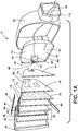
FIG. 1 is an outside front perspective view of an external rearview assembly of the present disclosure; -
FIG. 1A is a side perspective exploded view of an external rearview assembly of the present disclosure; -
FIG. 2 is a front perspective view of an external rearview assembly of the present disclosure, with the external rearview assembly in an extended position; -
FIG. 3 is a rear perspective view of the external rearview assembly ofFIG. 1 ; -
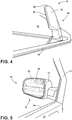
FIG. 4 is a top plan view of the external rearview assembly ofFIG. 1 ; -
FIG. 5 is an inside front perspective view of the external rearview assembly ofFIG. 1 ; -
FIG. 6 is an outside front perspective view of an external rearview assembly of the present disclosure, with the external rearview assembly in a retracted position; -
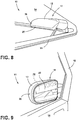
FIG. 7 is a rear perspective view of the external rearview assembly ofFIG. 6 ; -
FIG. 8 is a top plan view of the external rearview assembly ofFIG. 6 ; -
FIG. 9 is an inside front perspective view of the external rearview assembly ofFIG. 6 ; -
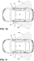
FIG. 10 is a top plan view of a vehicle of the present disclosure illustrating the field of view of a mirror element of the external rearview assembly; and -
FIG. 11 is a top plan view of a vehicle of the present disclosure illustrating the field of view of an imager of the external rearview assembly. - The present illustrated embodiments reside primarily in combinations of method steps and apparatus components related to a fold-in outside display mirror. Accordingly, the apparatus components and method steps have been represented, where appropriate, by conventional symbols in the drawings, showing only those specific details that are pertinent to understanding the embodiments of the present disclosure so as not to obscure the disclosure with details that will be readily apparent to those of ordinary skill in the art having the benefit of the description herein. Further, like numerals in the description and drawings represent like elements.
- For purposes of description herein, the terms "upper," "lower," "right," "left," "rear," "front," "vertical," "horizontal," and derivatives thereof, shall relate to the disclosure as oriented in
FIG. 1 . Unless stated otherwise, the term "front" shall refer to the surface of the device closer to the intended viewer, and the term "rear" shall refer to the surface of the device further from the intended viewer. However, it is to be understood that the disclosure may assume various alternative orientations, except where expressly specified to the contrary. It is also to be understood that the specific devices and processes illustrated in the attached drawings, and described in the following specification are simply exemplary embodiments of the inventive concepts defined in the appended claims. Hence, specific dimensions and other physical characteristics relating to the embodiments disclosed herein are not to be considered as limiting, unless the claims expressly state otherwise. - The terms "including," "comprises," "comprising," or any other variation thereof, are intended to cover a non-exclusive inclusion, such that a process, method, article, or apparatus that comprises a list of elements does not include only those elements but may include other elements not expressly listed or inherent to such process, method, article, or apparatus. An element preceded by "comprises a ..." does not, without more constraints, preclude the existence of additional identical elements in the process, method, article, or apparatus that comprises the element.
- Referring to
FIGS. 1-11 ,reference numeral 10 generally designates an external rearview assembly that includes ahousing 12 pivotally coupled with avehicle door 14 of avehicle 15 and operable between an extendedposition 16 and a retractedposition 18. An electro-optic element 20 is operably coupled with thehousing 12. Adisplay module 22 is disposed proximate the electro-optic element 20. Thedisplay module 22 is activated when thehousing 12 is in the retractedposition 18. Thedisplay module 22 is deactivated when thehousing 12 is in the extendedposition 16. Animager 24 is operably coupled with thehousing 12 and is configured to capture image data through animager lens 26 when thehousing 12 is in the retractedposition 18 and display the image data on the activateddisplay module 22. - With reference now to an exemplary embodiment as shown in
FIGS. 1 and1A , the illustratedexternal rearview assembly 10 includes theexterior housing 12, the electro-optic element 20, acircuit board 34, thedisplay module 22, acarrier plate 36, and abezel 37 with thecircuit board 34 disposed between the electro-optic element 20 and thecarrier plate 36. Theexternal rearview assembly 10 may be held together by a snap-fit connection, interference fit connection, mechanical fasteners, or adhesives. The electro-optic element 20 may be made of glass or any other material or material combination configured for use in exterior mirror applications. The electro-optic element 20 used in the inventive structure can have any contour, including flat, aspheric, or convex, depending on the type of reflection desired. In addition, the electro-optic element 20 can be an electrochromic mirror having front andrear substrates 40, 42, with an electro-optic medium disposed therebetween. It is also contemplated that afront surface 43 or arear surface 44 of therear substrate 42 may include a reflective layer configured to display a reflection through the electro-optic medium and the front substrate 40. A seal 46 extends around a periphery of first and second substrates, between the front andrear substrates 40, 42, thereby sealing the material between the substrates. Abus bar 48 is disposed proximate top and bottom edges of the front andrear substrates 40, 42. - With reference again to
FIG. 1A , thecircuit board 34 may be a flexible circuit board or a rigid circuit board. In one instance, a printed circuit board is utilized because of its thin construction, thereby reducing the vertical profile of theexternal rearview assembly 10 and minimizing the amount of space that theexternal rearview assembly 10 occupies in thehousing 12. Also, the flexibility of theprinted circuit board 34 allows thecircuit board 34 to follow the contours of the electro-optic element 20 smoothly and ensure good contact between the mating surfaces of thecircuit board 34 and the electro-optic element 20. Thecircuit board 34 can be a monolithic, unitary structure formed from one type of board material, or it can be made from two or more types of board material bonded or connected together by any known means. Thecircuit board 34 can be any shape and occupy any portion of the electro-optic element 20. However, for the reasons explained herein, thecircuit board 34 covers substantially the entire rear surface of the electro-optic element 20.Electronic components 60 of theexternal rearview assembly 10 may be arranged on thecircuit board 34 so that the mass of thecomponents 60 is near the center of gravity of theexternal rearview assembly 10 to minimize vibration of theexternal rearview assembly 10 after installation into the vehicle 15 (FIG. 2 ). Thecircuit board 34 is also operably coupled with theimager 24 and configured to activate and deactivate theimager 24, depending on the position of thehousing 12. Fasteners may be disposed about thecircuit board 34 to couple thecircuit board 34 to other internal components or thehousing 12. - As illustrated in
FIG. 1A , thecircuit board 34 drives aheater 70, which also extends across substantially all of a back side of thedisplay module 22 and thecircuit board 34. Theheater 70 includes aconductive track 72. Thecircuit board 34, which has an area that occupies substantially all of a rear surface of the electro-optic element 20, enables aheat conductor 73, which is on thecircuit board 34 and in communication with theconductive track 72. Generally, the electro-optic element 20 and thedisplay module 22 may act as a heat sink for thecircuit board 34 by way of theheater 70. At the same time, theheat conductor 73 heats the electro-optic element 20 and thedisplay module 22, resulting in better performance of these modules. In this instance, thecircuit board 34 may have theconductive track 72 on one side and theelectronic components 60 on the other side. The larger coverage of theconductive track 72 area provides improved heat distribution over the electro-optic element 20 and thedisplay module 22 and more efficient dissipation of heat from thecircuit board 34 to the electro-optic element 20. The material used to form theconductive track 72 can be metal (e.g. copper), metal alloy, conductive ink, or any other conductive material. If conductive ink having a positive temperature coefficient, such as printed silver ink, is used to form theconductive track 72, a separate thermostat may not be necessary because the resistance of the ink increases rapidly as the temperature of the ink increases, making theconductive track 72 self-governing. By placing theconductive track 72 directly on thecircuit board 34, on the surface opposite theelectronic components 60 and in contact with the electro-optic element 20, theconductive track 72 allows efficient dissipation of heat away from thecircuit board 34 and also allows the electro-optic element 20 to act as a heat sink at the same time. Further, theconductive track 72 acts heats the front substrate 40 of the electro-optic element 20, minimizing or eliminating any buildup of ice and mist on a first surface of the front substrate 40 of the electro-optic element 20. A thermostat or other heater control can also be provided in theelectronic components 60 on thecircuit board 34 and connected to theconductive track 72 so that heat flowing through theconductive track 72 can be controlled by, for example, pulse width modulation via a switching mechanism. It is also within the scope of the disclosure for a microprocessor on thecircuit board 34 to provide temperature control internally of the circuitry. Theelectronic components 60 include aplug 74 that may be operably coupled with theimager 24. - The
carrier plate 36 may be formed of molded plastic and may have aperipheral edge 80 defining acentral void 82. Theperipheral edge 80 is provided to accommodate mounting of amotor pack 83 proximate the void 82, which drives movement of the externalrearview assembly 10 relative to theexterior housing 12 to change the angle of reflection visible by a driver. The electro-optic element 20 and thedisplay module 22 are nested within thecarrier plate 36 inside thehousing 12. The void 82 is also sized to efficiently accommodate theimager 24. Theimager 24 is disposed within thehousing 12 and is in optical communication with theimager lens 26 positioned on thehousing 12. Theimager 24 includes alens barrel 81 adjacent to theperipheral edge 80 of thecarrier plate 36. To connect thecomponents 60 of the externalrearview assembly 10, an adhesive liquid or an adhesive tape orfilm 84, such as double-sided foam adhesive tape, may be provided between thecircuit board 34 and thecarrier plate 36 and attached over thecircuit board 34. Thefilm 84 includes anaperture 85 configured to accommodate theplug 74 so that it can attach with areceiver 86 on theimager 24. A power and/ordata line 90 extends from theimager 24 through thecarrier plate 36 and is operably coupled with a power source and/or data source of thevehicle 15. - With reference again to
FIG. 1A , thecircuit board 34 covers most or all of the rear surface of the electro-optic element 20. However, theelectronic components 60 are clustered closer to a center of thecircuit board 34. As can be seen inFIG. 1A , this arrangement allows theelectronic components 60 to sit within thevoid 82 of thecarrier plate 36 while allowing theconductive track 72 on the other side of thecircuit board 34 to cover as much of the surface of the electro-optic element 20 as possible. Theperipheral edge 80 is located at a mounting position of themotor pack 83 on thecarrier plate 36. If needed, theperipheral edge 80 can be made thicker to create additional vertical distance for accommodating theelectronic components 60 underneath thecarrier plate 36. - Referring now to
FIGS. 2-5 and10 , the externalrearview assembly 10 is configured to provide a reflected image to a driver of a view rearward of thevehicle 15. The externalrearview assembly 10 and be adjusted to provide an ideal field ofview 100 based on the size of the passenger. Thehousing 12 protects the electro-optic element 20 and theimager 24 from the elements and possible damage during regular use. It will be understood that the externalrearview assembly 10 may include various configurations including those set forth inU.S. Patent Nos. 7,324,261 ;6,195,194 ; and5,923,457 . - The external
rearview assembly 10 is also rotatable about a pivot axis X (FIG. 2 ) between the extended position 16 (FIGS. 2-5 and10 ) and the retracted position 18 (FIGS. 6-9 and11 ). Rotation of the externalrearview assembly 10 to the retractedposition 18 can be useful to keep the externalrearview assembly 10 from damage during washing of thevehicle 15 and to minimize the likelihood that another vehicle will strike the externalrearview assembly 10 when thevehicle 15 is parked. Typically, the externalrearview assembly 10 is not moved to the retractedposition 18 unless thevehicle 15 is parked. This is because a rear view of thevehicle 15 is not attainable when the externalrearview assembly 10 is folded inward toward thevehicle 15. Only a reflection of an internal portion of thevehicle 15 is reflected and visible. - With reference now to
FIGS. 6-9 and11 , in the present disclosure, upon rotation of the externalrearview assembly 10 to the retractedposition 18, theimager 24 is activated. The electro-optic element 20 is configured to darken when thehousing 12 is in theextended position 16 and lighten when thehousing 12 is in the retractedposition 18. Alternatively, the electro-optic element 20 may also be deactivated when thehousing 12 is in the retractedposition 18 so that a clear image can be provided to the driver. When the externalrearview assembly 10 is in the retractedposition 18, theimager 24 acquires image data and provides the image data to thedisplay module 22 so that a field ofview 102 can be displayed that is equal to or at least similar to the field ofview 100 provided by the electro-optic element 20 of the externalrearview assembly 10 when the externalrearview assembly 10 is in theextended position 16. Theimager 24 may be adjustable to provide a rearward field of view greater than or less than a field of view provided by the electro-optic element 20. It is generally contemplated that theimager 24 may be automatically activated upon rotation of the externalrearview assembly 10 from theextended position 16 to the retractedposition 18. However, it is also contemplated that theimager 24 may not be activated unless thevehicle 15 is in drive or reverse, or has otherwise been manually activated by the driver. For example, in the event a user is parking thevehicle 15 and wishes to move the externalrearview assembly 10 from theextended position 16 to the retractedposition 18, the user would simply park thevehicle 15 and manually adjust a motor 110 (FIG. 2 ) via an interface within thevehicle 15 to rotate the externalrearview assembly 10. In this instance, thevehicle 15 is parked and use of theimager 24 is unnecessary. However, if a driver was traveling within thevehicle 15 and desired a rearward view of thevehicle 15 via thedisplay module 22 rather than via the reflecting surface of the electro-optic element 20, the driver could simply activate themotor 110 of the externalrearview assembly 10 via the interface to move the externalrearview assembly 10 from theextended position 16 to the retractedposition 18. During rotation, an internal switch, which may be one of theelectronic components 60 on thecircuit board 34, could be actuated which would activate both theimager 24 and thedisplay module 22. Accordingly, a display of the rearview of thevehicle 15 within the field ofview 100 would be displayed on thedisplay module 22 through the electro-optic element 20 and visible to the driver. - With reference now to
FIGS. 10 and 11 , it will be generally understood that the rearward field ofview 100 provided by the reflective surface of the electro-optic element 20 when the externalrearview assembly 10 is in the extended position 16 (FIG. 10 ) is generally consistent with or at least similar with the rearward field ofview 100 acquired by theimager 24 shown on thedisplay module 22. Accordingly, the view that is provided by thedisplay module 22 is similar with the view provided by the reflected surface of electro-optic element 20. This configuration provides for improved visibility, and may also provide improved viewing of a blind spot location of thevehicle 15. In addition, theimager 24 may be adjustable so that a desired field of view is provided on thedisplay module 22. Enhanced or zooming functions may be capable with either or both of theimager 24 and thedisplay module 22. Further, an increase in fuel efficiency can be readily observed when the externalrearview assembly 10 is in the retractedposition 18 because the wind resistance of thehousing 12 of the externalrearview assembly 10 is lessened. - As previously noted, the external
rearview assembly 10, as set forth herein, is generally configured to include a lean profile so that the reflected image provided by the electro-optic element 20 may be the same as or similar to the field ofview 100 of theimager 24 when thehousing 12 is in the retractedposition 18. In addition, the activation of theimager 24 and thedisplay module 22 may occur automatically based on predetermined drivers who desire a displayed image rather than a reflected image available during driving. Safety features of the system may also be present. For example, the externalrearview assembly 10 may be configured to monitor thedisplay module 22 to confirm image data output. If image data is not being shown on thedisplay module 22, the externalrearview assembly 10 will automatically move thehousing 12 to theextended position 16 so that a reflected rearward view can be provided by the electro-optic element 20. - It will be understood by one having ordinary skill in the art that construction of the described disclosure and other components is not limited to any specific material. Other exemplary embodiments of the disclosure disclosed herein may be formed from a wide variety of materials, unless described otherwise herein.
- For purposes of this disclosure, the term "coupled" (in all of its forms, couple, coupling, coupled, etc.) generally means the joining of two components (electrical or mechanical) directly or indirectly to one another. Such joining may be stationary in nature or movable in nature. Such joining may be achieved with the two components (electrical or mechanical) and any additional intermediate members being integrally formed as a single unitary body with one another or with the two components. Such joining may be permanent in nature or may be removable or releasable in nature unless otherwise stated.
- It is also important to note that the construction and arrangement of the elements of the disclosure, as shown in the exemplary embodiments, is illustrative only. Although only a few embodiments of the present innovations have been described in detail in this disclosure, those skilled in the art who review this disclosure will readily appreciate that many modifications are possible (e.g., variations in sizes, dimensions, structures, shapes and proportions of the various elements, values of parameters, mounting arrangements, use of materials, colors, orientations, etc.) without materially departing from the novel teachings and advantages of the subject matter recited. For example, elements shown as integrally formed may be constructed of multiple parts, or elements shown as multiple parts may be integrally formed, the operation of the interfaces may be reversed or otherwise varied, the length or width of the structures and/or members or connector or other elements of the system may be varied, the nature or number of adjustment positions provided between the elements may be varied. It should be noted that the elements and/or assemblies of the system may be constructed from any of a wide variety of materials that provide sufficient strength or durability, in any of a wide variety of colors, textures, and combinations. Accordingly, all such modifications are intended to be included within the scope of the present invention as defined by the following claims. Other substitutions, modifications, changes, and omissions may be made in the design, operating conditions, and arrangement of the desired and other exemplary embodiments without departing from the present invention as defined by the following claims.
- It will be understood that any described processes or steps within described processes may be combined with other disclosed processes or steps to form structures within the scope of the present disclosure. The exemplary structures and processes disclosed herein are for illustrative purposes and are not to be construed as limiting.
- It is also to be understood that variations and modifications can be made on the aforementioned structures and methods without departing from the concepts of the present disclosure, and further it is to be understood that such concepts are intended to be covered by the following claims.
Claims (8)
- An external rearview assembly (10) comprising:a housing (12) pivotally coupled with a vehicle door (14) and operable between an extended position (16) and a retracted position (18);an electro-optic element (20) operably coupled with the housing (12), wherein the electro-optic element (20) is heated and configured to darken when the housing (12) is in the extended position (16) and lighten when the housing (12) is in the retracted position (18);a display module (22) disposed proximate the electro-optic element (20), wherein the display module (22) is activated when the housing (12) is in the retracted position (18), and wherein the display module (22) is deactivated when the housing (12) is in the extended position (16); andan imager (24) operably coupled with the housing (12) and configured to capture image data when the housing (12) is in the retracted position (18) and display the image data on the activated display module (22).
- The external rearview assembly (10) of claim 1, wherein the imager (24) is disposed within the housing (12) and is in optical communication with an imager lens (26) positioned on the housing (12).
- The external rearview assembly (10) of either of claims 1 or 2, wherein the imager (24) is adjustable to provide a rearward field of view greater than or less than a field of view provided by the electro-optic element (20).
- The external rearview assembly (10) of any of claims 1-3, wherein the electro-optic element (20) and the display module (22) are nested within a carrier plate (36) inside the housing (12).
- The external rearview assembly (10) of claim 4, wherein the imager (24) includes a lens barrel (81) adjacent to a peripheral edge (80) of the carrier plate (36).
- The external rearview assembly (10) of any of claims 1-5, further comprising:
a circuit board (34) operably coupled with the imager (24) and configured to activate and deactivate the imager (24). - The external rearview assembly (10) of claim 6, further comprising:
a heater (70) disposed between the circuit board (34) and the electro-optic element (20). - The external rearview assembly (10) of claim 7, wherein the heater (70) extends across substantially all of a back side of the display module (22) and the circuit board (34).
Applications Claiming Priority (2)
| Application Number | Priority Date | Filing Date | Title |
|---|---|---|---|
| US201662435290P | 2016-12-16 | 2016-12-16 | |
| PCT/US2017/066576 WO2018112292A1 (en) | 2016-12-16 | 2017-12-15 | Fold-in outside display mirror |
Publications (3)
| Publication Number | Publication Date |
|---|---|
| EP3554892A4 EP3554892A4 (en) | 2019-10-23 |
| EP3554892A1 EP3554892A1 (en) | 2019-10-23 |
| EP3554892B1 true EP3554892B1 (en) | 2021-01-27 |
Family
ID=62556578
Family Applications (1)
| Application Number | Title | Priority Date | Filing Date |
|---|---|---|---|
| EP17881543.7A Active EP3554892B1 (en) | 2016-12-16 | 2017-12-15 | Fold-in outside display mirror |
Country Status (6)
| Country | Link |
|---|---|
| US (1) | US11014500B2 (en) |
| EP (1) | EP3554892B1 (en) |
| JP (1) | JP7005626B2 (en) |
| KR (1) | KR102461245B1 (en) |
| CN (1) | CN109922993A (en) |
| WO (1) | WO2018112292A1 (en) |
Families Citing this family (5)
| Publication number | Priority date | Publication date | Assignee | Title |
|---|---|---|---|---|
| WO2018126164A1 (en) | 2016-12-30 | 2018-07-05 | Gentex Corporation | Vehicular outside rearview assembly |
| CN109747543B (en) * | 2019-03-08 | 2021-01-12 | 京东方科技集团股份有限公司 | Intelligent rearview mirror and control method thereof |
| JP7369796B2 (en) * | 2019-06-13 | 2023-10-26 | ジェンテックス コーポレイション | Switchable multi-view imaging system |
| EP4051539B1 (en) * | 2019-10-31 | 2023-10-18 | Gentex Corporation | Rotatable outside mirror with imager assembly |
| CN116661201B (en) * | 2023-06-01 | 2023-11-17 | 莆田市佳阳电子有限公司 | Anti-glare structure and rearview mirror |
Family Cites Families (34)
| Publication number | Priority date | Publication date | Assignee | Title |
|---|---|---|---|---|
| US4798967A (en) | 1988-03-24 | 1989-01-17 | Murakami Kaimeido Co | Control system for foldable outside rearview mirror |
| JPH04136949U (en) | 1991-06-17 | 1992-12-21 | 株式会社村上開明堂 | foldable door mirror |
| US5371659A (en) | 1993-02-01 | 1994-12-06 | Donnelly Corporation | Remote-actuated exterior vehicle security light |
| JP2901489B2 (en) * | 1994-03-29 | 1999-06-07 | アラコ株式会社 | Rearview mirror |
| US5923457A (en) | 1997-04-02 | 1999-07-13 | Gentex Corporation | Electro-optic device including a low sheet resistance, high transmission transparent electrode |
| JPH10297375A (en) | 1997-04-28 | 1998-11-10 | Yazaki Corp | Room mirror device for vehicle |
| US6195194B1 (en) | 1999-03-16 | 2001-02-27 | Gentex Corporation | Lightweight electrochromic mirror |
| US6244716B1 (en) | 1999-05-17 | 2001-06-12 | Gentex Corporation | Exterior mirror sub-assembly with combined electronic circuitry and mirror element |
| US7324261B2 (en) | 1999-07-09 | 2008-01-29 | Gentex Corporation | Electrochromic devices with thin bezel-covered edge |
| JP3298851B2 (en) * | 1999-08-18 | 2002-07-08 | 松下電器産業株式会社 | Multi-function vehicle camera system and image display method of multi-function vehicle camera |
| JP2003320898A (en) * | 2002-04-26 | 2003-11-11 | Sony Corp | Side mirror device for vehicle |
| JP3979330B2 (en) * | 2003-04-02 | 2007-09-19 | トヨタ自動車株式会社 | Image display device for vehicle |
| US8058977B2 (en) * | 2006-10-24 | 2011-11-15 | Donnelly Corporation | Exterior mirror having a display that can be viewed by a host driver or drivers of other vehicles |
| US7777611B2 (en) * | 2006-11-06 | 2010-08-17 | Donnelly Corporation | Display device for exterior rearview mirror |
| US20080204556A1 (en) * | 2007-02-23 | 2008-08-28 | De Miranda Federico Thoth Jorg | Vehicle camera security system |
| AU2008203505B2 (en) | 2008-08-05 | 2011-06-09 | Smr Patents S.A.R.L. | Vehicle mirror power fold mechanism |
| JP4770942B2 (en) | 2009-02-19 | 2011-09-14 | 株式会社デンソー | Outside-vehicle image display system and vehicle |
| US9205780B2 (en) * | 2010-02-04 | 2015-12-08 | Magna Mirrors Of America, Inc. | Electro-optic rearview mirror assembly for vehicle |
| US9827913B2 (en) * | 2010-02-10 | 2017-11-28 | Magna Mirrors Of America, Inc. | Exterior rearview mirror assembly |
| KR20120009153A (en) * | 2010-07-22 | 2012-02-01 | 강용주 | the back mirror equipped CCD camera at the end side for cars and bikes |
| US8879139B2 (en) | 2012-04-24 | 2014-11-04 | Gentex Corporation | Display mirror assembly |
| DE102012219810B4 (en) * | 2012-10-30 | 2019-11-07 | Bayerische Motoren Werke Aktiengesellschaft | Method and device for image processing of image data |
| US9676336B2 (en) * | 2013-06-25 | 2017-06-13 | Magna Mirrors Of America, Inc. | Exterior rearview mirror assembly for vehicle |
| JP6462218B2 (en) * | 2014-02-28 | 2019-01-30 | 株式会社村上開明堂 | Rear imaging device |
| JP2016035521A (en) | 2014-08-04 | 2016-03-17 | 株式会社村上開明堂 | Solid type ec mirror for vehicle |
| JP2016037109A (en) * | 2014-08-06 | 2016-03-22 | サカエ理研工業株式会社 | Rear visual recognition device |
| US10000154B2 (en) * | 2014-08-07 | 2018-06-19 | Ford Global Technologies, Llc | Vehicle camera system having live video indication |
| DE102014224795A1 (en) * | 2014-12-03 | 2016-06-09 | Conti Temic Microelectronic Gmbh | Method and system for representing a vehicle environment of a motor vehicle on a display device arranged in the motor vehicle |
| CN204472689U (en) * | 2014-12-31 | 2015-07-15 | 北京汽车研究总院有限公司 | A kind of vehicle with safe avoidance back mirror |
| CN107206939B (en) * | 2015-02-02 | 2019-10-18 | 本田技研工业株式会社 | Vehicle rearview mirror device |
| CN104742807B (en) * | 2015-04-15 | 2016-08-31 | 宁波精成车业有限公司 | Intelligence outside rear-view mirror |
| CN105744127B (en) * | 2015-11-13 | 2020-04-28 | 宁波舜宇光电信息有限公司 | Camera module and electrical support and assembling method thereof |
| US20170158136A1 (en) * | 2015-12-02 | 2017-06-08 | Ford Global Technologies, Llc | Vehicle side mirror system |
| JP6229769B2 (en) * | 2016-07-20 | 2017-11-15 | 株式会社Jvcケンウッド | Mirror device with display function and display switching method |
-
2017
- 2017-12-15 WO PCT/US2017/066576 patent/WO2018112292A1/en unknown
- 2017-12-15 EP EP17881543.7A patent/EP3554892B1/en active Active
- 2017-12-15 KR KR1020197015982A patent/KR102461245B1/en active IP Right Grant
- 2017-12-15 US US15/842,976 patent/US11014500B2/en active Active
- 2017-12-15 JP JP2019531119A patent/JP7005626B2/en active Active
- 2017-12-15 CN CN201780068766.5A patent/CN109922993A/en active Pending
Non-Patent Citations (1)
| Title |
|---|
| None * |
Also Published As
| Publication number | Publication date |
|---|---|
| KR102461245B1 (en) | 2022-11-01 |
| KR20190099200A (en) | 2019-08-26 |
| EP3554892A4 (en) | 2019-10-23 |
| EP3554892A1 (en) | 2019-10-23 |
| US11014500B2 (en) | 2021-05-25 |
| US20180170265A1 (en) | 2018-06-21 |
| JP2020500780A (en) | 2020-01-16 |
| JP7005626B2 (en) | 2022-01-21 |
| CN109922993A (en) | 2019-06-21 |
| WO2018112292A1 (en) | 2018-06-21 |
Similar Documents
| Publication | Publication Date | Title |
|---|---|---|
| EP3554892B1 (en) | Fold-in outside display mirror | |
| US10739591B2 (en) | Display mirror assembly | |
| US10829051B2 (en) | Interior rearview mirror assembly with display and tilt mechanism | |
| US11718232B2 (en) | Vehicular exterior rearview mirror assembly with extendable and retractable mirror head | |
| US10807535B2 (en) | Full display rearview device | |
| JP6689964B2 (en) | Toggle mechanism for rearview mirror assembly | |
| US20140133044A1 (en) | Exterior mirror assembly with actuator | |
| EP3390156B1 (en) | Bimodal mechanism with optical switch | |
| CN114555421B (en) | Rotatable external mirror with imager assembly | |
| CN211196041U (en) | Rearview assembly | |
| US20210221290A1 (en) | Rearview mirror assembly with flexible glass substrate | |
| US20190023184A1 (en) | Side mirror assembly with integrated spotter mirror |
Legal Events
| Date | Code | Title | Description |
|---|---|---|---|
| STAA | Information on the status of an ep patent application or granted ep patent |
Free format text: STATUS: THE INTERNATIONAL PUBLICATION HAS BEEN MADE |
|
| PUAI | Public reference made under article 153(3) epc to a published international application that has entered the european phase |
Free format text: ORIGINAL CODE: 0009012 |
|
| STAA | Information on the status of an ep patent application or granted ep patent |
Free format text: STATUS: REQUEST FOR EXAMINATION WAS MADE |
|
| 17P | Request for examination filed |
Effective date: 20190711 |
|
| A4 | Supplementary search report drawn up and despatched |
Effective date: 20190903 |
|
| AK | Designated contracting states |
Kind code of ref document: A1 Designated state(s): AL AT BE BG CH CY CZ DE DK EE ES FI FR GB GR HR HU IE IS IT LI LT LU LV MC MK MT NL NO PL PT RO RS SE SI SK SM TR |
|
| AX | Request for extension of the european patent |
Extension state: BA ME |
|
| DAV | Request for validation of the european patent (deleted) | ||
| DAX | Request for extension of the european patent (deleted) | ||
| GRAP | Despatch of communication of intention to grant a patent |
Free format text: ORIGINAL CODE: EPIDOSNIGR1 |
|
| STAA | Information on the status of an ep patent application or granted ep patent |
Free format text: STATUS: GRANT OF PATENT IS INTENDED |
|
| INTG | Intention to grant announced |
Effective date: 20200904 |
|
| GRAS | Grant fee paid |
Free format text: ORIGINAL CODE: EPIDOSNIGR3 |
|
| GRAA | (expected) grant |
Free format text: ORIGINAL CODE: 0009210 |
|
| STAA | Information on the status of an ep patent application or granted ep patent |
Free format text: STATUS: THE PATENT HAS BEEN GRANTED |
|
| AK | Designated contracting states |
Kind code of ref document: B1 Designated state(s): AL AT BE BG CH CY CZ DE DK EE ES FI FR GB GR HR HU IE IS IT LI LT LU LV MC MK MT NL NO PL PT RO RS SE SI SK SM TR |
|
| REG | Reference to a national code |
Ref country code: GB Ref legal event code: FG4D |
|
| REG | Reference to a national code |
Ref country code: CH Ref legal event code: EP |
|
| REG | Reference to a national code |
Ref country code: AT Ref legal event code: REF Ref document number: 1358061 Country of ref document: AT Kind code of ref document: T Effective date: 20210215 |
|
| REG | Reference to a national code |
Ref country code: IE Ref legal event code: FG4D |
|
| REG | Reference to a national code |
Ref country code: DE Ref legal event code: R096 Ref document number: 602017032298 Country of ref document: DE |
|
| REG | Reference to a national code |
Ref country code: NL Ref legal event code: MP Effective date: 20210127 |
|
| REG | Reference to a national code |
Ref country code: LT Ref legal event code: MG9D |
|
| REG | Reference to a national code |
Ref country code: AT Ref legal event code: MK05 Ref document number: 1358061 Country of ref document: AT Kind code of ref document: T Effective date: 20210127 |
|
| PG25 | Lapsed in a contracting state [announced via postgrant information from national office to epo] |
Ref country code: LT Free format text: LAPSE BECAUSE OF FAILURE TO SUBMIT A TRANSLATION OF THE DESCRIPTION OR TO PAY THE FEE WITHIN THE PRESCRIBED TIME-LIMIT Effective date: 20210127 Ref country code: BG Free format text: LAPSE BECAUSE OF FAILURE TO SUBMIT A TRANSLATION OF THE DESCRIPTION OR TO PAY THE FEE WITHIN THE PRESCRIBED TIME-LIMIT Effective date: 20210427 Ref country code: GR Free format text: LAPSE BECAUSE OF FAILURE TO SUBMIT A TRANSLATION OF THE DESCRIPTION OR TO PAY THE FEE WITHIN THE PRESCRIBED TIME-LIMIT Effective date: 20210428 Ref country code: FI Free format text: LAPSE BECAUSE OF FAILURE TO SUBMIT A TRANSLATION OF THE DESCRIPTION OR TO PAY THE FEE WITHIN THE PRESCRIBED TIME-LIMIT Effective date: 20210127 Ref country code: HR Free format text: LAPSE BECAUSE OF FAILURE TO SUBMIT A TRANSLATION OF THE DESCRIPTION OR TO PAY THE FEE WITHIN THE PRESCRIBED TIME-LIMIT Effective date: 20210127 Ref country code: NO Free format text: LAPSE BECAUSE OF FAILURE TO SUBMIT A TRANSLATION OF THE DESCRIPTION OR TO PAY THE FEE WITHIN THE PRESCRIBED TIME-LIMIT Effective date: 20210427 Ref country code: PT Free format text: LAPSE BECAUSE OF FAILURE TO SUBMIT A TRANSLATION OF THE DESCRIPTION OR TO PAY THE FEE WITHIN THE PRESCRIBED TIME-LIMIT Effective date: 20210527 |
|
| PG25 | Lapsed in a contracting state [announced via postgrant information from national office to epo] |
Ref country code: SE Free format text: LAPSE BECAUSE OF FAILURE TO SUBMIT A TRANSLATION OF THE DESCRIPTION OR TO PAY THE FEE WITHIN THE PRESCRIBED TIME-LIMIT Effective date: 20210127 Ref country code: RS Free format text: LAPSE BECAUSE OF FAILURE TO SUBMIT A TRANSLATION OF THE DESCRIPTION OR TO PAY THE FEE WITHIN THE PRESCRIBED TIME-LIMIT Effective date: 20210127 Ref country code: PL Free format text: LAPSE BECAUSE OF FAILURE TO SUBMIT A TRANSLATION OF THE DESCRIPTION OR TO PAY THE FEE WITHIN THE PRESCRIBED TIME-LIMIT Effective date: 20210127 Ref country code: LV Free format text: LAPSE BECAUSE OF FAILURE TO SUBMIT A TRANSLATION OF THE DESCRIPTION OR TO PAY THE FEE WITHIN THE PRESCRIBED TIME-LIMIT Effective date: 20210127 Ref country code: AT Free format text: LAPSE BECAUSE OF FAILURE TO SUBMIT A TRANSLATION OF THE DESCRIPTION OR TO PAY THE FEE WITHIN THE PRESCRIBED TIME-LIMIT Effective date: 20210127 |
|
| PG25 | Lapsed in a contracting state [announced via postgrant information from national office to epo] |
Ref country code: IS Free format text: LAPSE BECAUSE OF FAILURE TO SUBMIT A TRANSLATION OF THE DESCRIPTION OR TO PAY THE FEE WITHIN THE PRESCRIBED TIME-LIMIT Effective date: 20210527 |
|
| REG | Reference to a national code |
Ref country code: DE Ref legal event code: R097 Ref document number: 602017032298 Country of ref document: DE |
|
| PG25 | Lapsed in a contracting state [announced via postgrant information from national office to epo] |
Ref country code: SM Free format text: LAPSE BECAUSE OF FAILURE TO SUBMIT A TRANSLATION OF THE DESCRIPTION OR TO PAY THE FEE WITHIN THE PRESCRIBED TIME-LIMIT Effective date: 20210127 Ref country code: CZ Free format text: LAPSE BECAUSE OF FAILURE TO SUBMIT A TRANSLATION OF THE DESCRIPTION OR TO PAY THE FEE WITHIN THE PRESCRIBED TIME-LIMIT Effective date: 20210127 Ref country code: EE Free format text: LAPSE BECAUSE OF FAILURE TO SUBMIT A TRANSLATION OF THE DESCRIPTION OR TO PAY THE FEE WITHIN THE PRESCRIBED TIME-LIMIT Effective date: 20210127 |
|
| PG25 | Lapsed in a contracting state [announced via postgrant information from national office to epo] |
Ref country code: RO Free format text: LAPSE BECAUSE OF FAILURE TO SUBMIT A TRANSLATION OF THE DESCRIPTION OR TO PAY THE FEE WITHIN THE PRESCRIBED TIME-LIMIT Effective date: 20210127 Ref country code: DK Free format text: LAPSE BECAUSE OF FAILURE TO SUBMIT A TRANSLATION OF THE DESCRIPTION OR TO PAY THE FEE WITHIN THE PRESCRIBED TIME-LIMIT Effective date: 20210127 Ref country code: SK Free format text: LAPSE BECAUSE OF FAILURE TO SUBMIT A TRANSLATION OF THE DESCRIPTION OR TO PAY THE FEE WITHIN THE PRESCRIBED TIME-LIMIT Effective date: 20210127 |
|
| PLBE | No opposition filed within time limit |
Free format text: ORIGINAL CODE: 0009261 |
|
| STAA | Information on the status of an ep patent application or granted ep patent |
Free format text: STATUS: NO OPPOSITION FILED WITHIN TIME LIMIT |
|
| 26N | No opposition filed |
Effective date: 20211028 |
|
| PG25 | Lapsed in a contracting state [announced via postgrant information from national office to epo] |
Ref country code: AL Free format text: LAPSE BECAUSE OF FAILURE TO SUBMIT A TRANSLATION OF THE DESCRIPTION OR TO PAY THE FEE WITHIN THE PRESCRIBED TIME-LIMIT Effective date: 20210127 Ref country code: ES Free format text: LAPSE BECAUSE OF FAILURE TO SUBMIT A TRANSLATION OF THE DESCRIPTION OR TO PAY THE FEE WITHIN THE PRESCRIBED TIME-LIMIT Effective date: 20210127 |
|
| PG25 | Lapsed in a contracting state [announced via postgrant information from national office to epo] |
Ref country code: SI Free format text: LAPSE BECAUSE OF FAILURE TO SUBMIT A TRANSLATION OF THE DESCRIPTION OR TO PAY THE FEE WITHIN THE PRESCRIBED TIME-LIMIT Effective date: 20210127 |
|
| PG25 | Lapsed in a contracting state [announced via postgrant information from national office to epo] |
Ref country code: IT Free format text: LAPSE BECAUSE OF FAILURE TO SUBMIT A TRANSLATION OF THE DESCRIPTION OR TO PAY THE FEE WITHIN THE PRESCRIBED TIME-LIMIT Effective date: 20210127 |
|
| PG25 | Lapsed in a contracting state [announced via postgrant information from national office to epo] |
Ref country code: IS Free format text: LAPSE BECAUSE OF FAILURE TO SUBMIT A TRANSLATION OF THE DESCRIPTION OR TO PAY THE FEE WITHIN THE PRESCRIBED TIME-LIMIT Effective date: 20210527 |
|
| PG25 | Lapsed in a contracting state [announced via postgrant information from national office to epo] |
Ref country code: MC Free format text: LAPSE BECAUSE OF FAILURE TO SUBMIT A TRANSLATION OF THE DESCRIPTION OR TO PAY THE FEE WITHIN THE PRESCRIBED TIME-LIMIT Effective date: 20210127 |
|
| REG | Reference to a national code |
Ref country code: CH Ref legal event code: PL |
|
| REG | Reference to a national code |
Ref country code: BE Ref legal event code: MM Effective date: 20211231 |
|
| PG25 | Lapsed in a contracting state [announced via postgrant information from national office to epo] |
Ref country code: LU Free format text: LAPSE BECAUSE OF NON-PAYMENT OF DUE FEES Effective date: 20211215 Ref country code: IE Free format text: LAPSE BECAUSE OF NON-PAYMENT OF DUE FEES Effective date: 20211215 |
|
| PG25 | Lapsed in a contracting state [announced via postgrant information from national office to epo] |
Ref country code: BE Free format text: LAPSE BECAUSE OF NON-PAYMENT OF DUE FEES Effective date: 20211231 |
|
| PG25 | Lapsed in a contracting state [announced via postgrant information from national office to epo] |
Ref country code: LI Free format text: LAPSE BECAUSE OF NON-PAYMENT OF DUE FEES Effective date: 20211231 Ref country code: CH Free format text: LAPSE BECAUSE OF NON-PAYMENT OF DUE FEES Effective date: 20211231 |
|
| P01 | Opt-out of the competence of the unified patent court (upc) registered |
Effective date: 20230503 |
|
| PG25 | Lapsed in a contracting state [announced via postgrant information from national office to epo] |
Ref country code: NL Free format text: LAPSE BECAUSE OF NON-PAYMENT OF DUE FEES Effective date: 20210127 Ref country code: CY Free format text: LAPSE BECAUSE OF FAILURE TO SUBMIT A TRANSLATION OF THE DESCRIPTION OR TO PAY THE FEE WITHIN THE PRESCRIBED TIME-LIMIT Effective date: 20210127 |
|
| PG25 | Lapsed in a contracting state [announced via postgrant information from national office to epo] |
Ref country code: HU Free format text: LAPSE BECAUSE OF FAILURE TO SUBMIT A TRANSLATION OF THE DESCRIPTION OR TO PAY THE FEE WITHIN THE PRESCRIBED TIME-LIMIT; INVALID AB INITIO Effective date: 20171215 |
|
| PGFP | Annual fee paid to national office [announced via postgrant information from national office to epo] |
Ref country code: GB Payment date: 20231121 Year of fee payment: 7 |
|
| PGFP | Annual fee paid to national office [announced via postgrant information from national office to epo] |
Ref country code: FR Payment date: 20231122 Year of fee payment: 7 Ref country code: DE Payment date: 20231121 Year of fee payment: 7 |