EP3554890B1 - Lit suspendu - Google Patents
Lit suspendu Download PDFInfo
- Publication number
- EP3554890B1 EP3554890B1 EP17832810.0A EP17832810A EP3554890B1 EP 3554890 B1 EP3554890 B1 EP 3554890B1 EP 17832810 A EP17832810 A EP 17832810A EP 3554890 B1 EP3554890 B1 EP 3554890B1
- Authority
- EP
- European Patent Office
- Prior art keywords
- cogwheel
- pulley
- bed
- drive element
- linear drive
- Prior art date
- Legal status (The legal status is an assumption and is not a legal conclusion. Google has not performed a legal analysis and makes no representation as to the accuracy of the status listed.)
- Active
Links
Images

Classifications
-
- B—PERFORMING OPERATIONS; TRANSPORTING
- B60—VEHICLES IN GENERAL
- B60P—VEHICLES ADAPTED FOR LOAD TRANSPORTATION OR TO TRANSPORT, TO CARRY, OR TO COMPRISE SPECIAL LOADS OR OBJECTS
- B60P3/00—Vehicles adapted to transport, to carry or to comprise special loads or objects
- B60P3/32—Vehicles adapted to transport, to carry or to comprise special loads or objects comprising living accommodation for people, e.g. caravans, camping, or like vehicles
- B60P3/36—Auxiliary arrangements; Arrangements of living accommodation; Details
- B60P3/38—Sleeping arrangements, e.g. living or sleeping accommodation on the roof of the vehicle
- B60P3/39—Sleeping arrangements, e.g. living or sleeping accommodation on the roof of the vehicle expansible, collapsible or repositionable elements adapted to support a bed, e.g. wall portions
-
- B—PERFORMING OPERATIONS; TRANSPORTING
- B60—VEHICLES IN GENERAL
- B60N—SEATS SPECIALLY ADAPTED FOR VEHICLES; VEHICLE PASSENGER ACCOMMODATION NOT OTHERWISE PROVIDED FOR
- B60N3/00—Arrangements or adaptations of other passenger fittings, not otherwise provided for
- B60N3/008—Arrangements or adaptations of other passenger fittings, not otherwise provided for of beds
Definitions
- the present invention relates to the technical field inherent to furniture for caravans, campers, motor homes, cabin boats and the like, with particular reference to the foldaway beds.
- One of the most used systems for optimizing spaces is the hinged articulation of the furnishing elements, so as to be able to rotate them, or overturn them in order to dispose them in conditions of use or rest, depending on the case.
- Another constructive method used for some types of beds requires that they are suspended, so that they can be lowered when needed and lifted when not needed, so as to move their encumbrance to a position where they disturb less.
- each rope has an upper end hanging from a fixed support, for example the roof of the cabin, from which a substantially vertical branch extends ending where the rope engages under a return pulley provided in the bed, from which it is then deflected below the latter, substantially horizontally.
- All the ropes therefore, belong to a device, housed under the same bed and shaped as much as possible flattened, designed to pull, collect and hold an equal length of each rope during the lifting and, vice versa, to release equal amount during the lowering of the bed.
- the slide is slidable along a rectilinear guide, by the action of a linear actuator, arranged parallel to said guide and capable of imparting to the same slide a first stroke in which the four ropes are simultaneously pulled, determining the lifting of the bed.
- the linear actuator is constituted by a gas spring, whose active extension stroke is accomplished during the lifting of the bed.
- the linear actuator is of motorized type.
- the device described and protected in the document mentioned above requires a unitary relationship between the stroke of the actuator, that of the slide and the length of the pulled or released ropes stretches, so that necessarily even the amplitude of the ascent and descent movement of the bed has the same value.
- the device does not allow any calibration maneuver that allows to modify the balances and therefore the response, for example to adapt it to variations in the total weight of the bed, due to different mattresses or blankets or other.
- Another example of suspended bed is shown in KR20140027789 A .
- Object of the present invention is therefore to propose a device for operating a lifting system of a suspended bed which is shaped so as to be at the same time compact, reliable in operation and able to overcome the drawbacks of known devices and, in particular, of that referred to in said document.
- Another object of the invention is to provide a device in which it is possible to obtain a considerable vertical excursion of the bed, without this leading to constructive complications.
- a further object of the invention is to provide the device with locking means to stabilize at least the maximum lifting position.
- Yet another object of the invention is to obtain a simple and low-cost device.
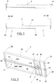
- the device 1 is adapted to operate a lifting mechanism 2 of a suspended bed 3, for example of the type mentioned in the introduction, provided in caravans, campers, motor homes, cabin boats and the like.
- the lifting mechanism 2 comprises a supporting frame 20 for said bed 3, of rectangular shape, and at least four ropes 21, 22, 23, 24, each of them fixed in suspension to a fixed structure A at the top, consisting for example of the cabin roof of one of said vehicles.
- Each rope 21, 22, 23, 24 is extended downwards close to a corresponding corner of said supporting frame 20, to then sequentially engages returning rollers 25, provided in the latter with suitable positions and orientations, for deviating the same rope according to a predetermined path that ends with a horizontal portion 21H, 22H, 23H, 24H, arranged beneath said supporting frame 20 and almost parallel to the corresponding horizontal portions 21H, 22H, 23H, 24H of the remaining ropes.
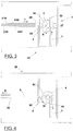
- the latter comprises at least one pulley 4, which can be rotated by a cross-member 27 of the supporting frame 20, with substantially vertical rotation axis.
- the pulley 4 coaxially supports, on one side, a cogwheel 40, of a suitably inferior diameter.
- a linear drive element 5 is made integral, with an end of its own, to the supporting frame 20 and having associated with the other end of its own, motion transformation means which transform said translation into a synchronous rotation of said cogwheel (40) and pulley (4). More specifically, in the embodiment of Figs 2 , 3 and 4 the motion transformation means are constituted by a rack 50, extended parallel to the element 5 itself and intended to gear with said cogwheel 40 to rotate it together with said pulley 4.
- the device 1 further comprises a flexible cable 6, fixed with one end to said pulley 4 and wound on the latter with an intermediate portion of its own, for then engaging at least one returning roller 60 arranged downstream of the latter and being fixed, with the remaining end, to said draw hook 26 of the ropes 21, 22, 23, 24.
- said linear drive element 5 is constituted by a gas spring, whose push action is directed to impart a translation of said rack 50 and, consequently, a synchronous rotation of said cogwheel 40 and pulley 4 according to a direction concordant with the lifting action of the bed 3, as further specified below.
- Said locking means are of substantially known type and therefore are not shown in detail; by way of example, they can be constituted by a pin, or a pawl, which snaps into position by engaging a hole or a tooth in the pulley 4 or in the rack 50, upon reaching said raised position of said bed 3.
- the release is made by a manual control (also not shown) brought to the side of the bed 3 by a suitable linkage.
- the operation of the device 1 thus produced, however already partially anticipated by the description above, provides that the raising of the bed 3 is at least facilitated by the pushing action of the gas spring 5, which acting on the pulley 4 through the rack 50 and the cogwheel 40 makes it rotate in a first direction K, in which the flexible cable 6 pulls the draw hook 26 (arrow T in Fig. 3 ), determining for it a rectilinear excursion proportional to the development of the winding circumference on the pulley 4 and, consequently, equal pull stresses on the ropes 21, 22, 23, 24.
- the lowering of the bed 3, vice versa is at least partly determined by the gravity, so that the ropes 21, 22, 23, 24 drag in the opposite direction the draw hook 26 (arrow R in Fig. 4 ) which, in turn, pull the flexible cable 6; the pulley 4 is therefore driven to rotate in the opposite direction W, causing the return of the stem 50 of the gas spring 5, which is thus recharged.
- the linear drive element 5 is costituted by a motorized actuator; the operation of the device 1 remains substantially unchanged regarding the movement of the pulley 4, of the flexible cable 6, of the draw hook 26 and of the ropes 21, 22, 23, 24, except for the fact that the ascent and descent movements of the bed 3 become fully automatic and do not require any manual intervention or "help".
- the presence of said locking means may not be necessary, since the motorized actuator could advantageously be of the self-braking type.
- said linear drive element 5 comprises a gas spring 5A, associated with the rack 50 for determining the rotation with same direction of said cogwheel 40 and pulley 4, similarly to what previously described.
- a ring gear 41 is integral with (or realized into) the outer circumference of said pulley 4, and it is present a geared motor 5B, on whose output shaft is keyed a pinion 51 engaged with the ring gear 41.
- the geared motor 5B is adapted to cooperate with said gas spring 5A to determine the rotation in the two directions K, W of the pulley 4, then the ascent and descent of the bed 3
- the locking means are in fact incorporated into the drive members, for example if the gear unit is of the endless screw and helical wheel type therefore, as is known, irreversible in the motion direction.
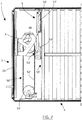
- FIG. 7 A further embodiment is shown in Fig. 7 in which it is shown a frame complete with a bed 3, but in which, for representation simplicity, it is not shown the system of ropes and return pulleys that are part of the lifting mechanism 2, but which, also in this embodiment, are arranged in a way functionally similar to the one shown in the previous figures.
- the linear drive element 5 comprises two gas springs, 56', 57', arranged parallel one next to the other, connected in succession one to the other and in which one of them is integral with the frame 20 supporting the bed while the other is integral with the motion transformation means, so as to double the useful stroke of the linear drive element 5 with the same minimum encumbrance in the drive direction.
- the motion transformation means consist of a second cogwheel 51', substantially coplanar to the cogwheel 40 and having axis rotatably integral with said supporting frame 20 and of a transmission chain, 50', closed in a loop between the cogwheel 40 and the second cogwheel 51'.
- the second end of the linear drive element 5 is made integral with chain links, 53', of said transmission chain 50', so that the actuation of the linear drive element 5 moves the chain links 53' along the closed path of the transmission chain 50' causing the cogwheel 40 to rotate and thereby causing the bed 3 to be lifted or lowered.
- the second cogwheel 51' is arranged such that at least a linear portion, 52', of the transmission chain 50' runs parallel to the actuation direction of the linear drive element 5.
- the motion transformation means further comprises a skid, 54', driven to move in a guide rail, 55', integral with the frame 20 and arranged according to the direction of the linear portion 52'.
- the skid 54' is integral with the second end of the linear drive element 5 as well as with chain links 53' of said linear portion 52'. Thanks to said construction, the actuation of the linear drive element 5 moves the skid 54' along the guide rail 55', thus bringing the transmission chain 50' into motion which in turn drives the cogwheel 40 in rotation.
- This last embodiment is particularly solid and reliable over time thanks to the possibility of making solid and secure couplings between the various motion transmission components.
- the vertical excursion possible for the bed can become very wide, thanks to the amplification effect given by a large diameter pulley, which can be easily adopted without particular complications.
Landscapes
- Engineering & Computer Science (AREA)
- Transportation (AREA)
- Mechanical Engineering (AREA)
- Health & Medical Sciences (AREA)
- Public Health (AREA)
- Transmission Devices (AREA)
- Invalid Beds And Related Equipment (AREA)
Claims (8)
- Lit suspendu (3) comprenant un mécanisme de levage (2) et un dispositif (1) pour entraîner ledit mécanisme de levage, où le mécanisme (2) comprend un cadre de support (20) audit lit (3), de forme rectangulaire, et au moins quatre câbles (21, 22, 23, 24), dont chacun est fixé à sa partie supérieure à une structure fixe (A), lesdits au moins quatre câbles (21, 22, 23, 24) s'étendant vers le bas jusqu'à un bord correspondant dudit cadre de support (20), puis pour engager séquentiellement des rouleaux de retour (25), prévus dans le cadre de support (20) pour dévier les mêmes câbles (21, 22, 23, 24) selon une trajectoire prédéterminée qui se termine par une partie horizontale (21H, 22H, 23H, 24H), déplacée au-dessous du cadre de support mentionné (20) et presque parallèle aux parties horizontales correspondantes (21H, 22H, 23H, 24H) des câbles restants (21, 22, 23, 24), avec toutes les extrémités respectives liées à un crochet de traction commun (26), qui est prévu pour être déplacé avec les mêmes câbles (21, 22, 23, 24), où ledit dispositif (1) comprend :- au moins une poulie (4), portée de manière rotative par le cadre de support mentionné (20), avec un axe de rotation sensiblement vertical ;- une roue dentée (40), solidaire coaxialement de ladite poulie (4);- un élément d'entraînement linéaire (5), solidaire à l'une de ses extrémités dudit cadre de support (20) et auquel sont associés, à son autre extrémité, des moyens de transformation de mouvement ;- un câble flexible (6), lié à une extrémité à ladite poulie (4) et enroulé autour de ladite poulie (4) avec une partie intermédiaire de celle-ci engagée avec au moins un rouleau de retour (60) disposé en aval et fixé avec l'extrémité restante audit crochet de traction (26) des câbles (21, 22, 23, 24), de sorte qu'à la rotation de la poulie (4) et de la roue dentée (40) correspond un entraînement du même câble flexible (6) pour conférer/permettre au crochet de traction mentionné (26) des mouvements rectilignes, respectivement dans une première direction, où le même crochet (26) et les câbles (21, 22, 23, 24) sont tirés pour soulever ledit lit (3), et dans une direction opposée, en relation de phase avec la descente du même lit (3), où au crochet (26) et aux câbles (21, 22, 23, 24) est autorisée une course de retour,
où lesdits moyens de transformation de mouvement sont constitués d'au moins une seconde roue dentée (51') sensiblement coplanaire à ladite roue dentée (40) et ayant un axe solidaire en rotation dudit cadre de support (20) et d'une chaîne de transmission (50') fermée en boucle entre ladite au moins une seconde roue dentée (51') et ladite roue dentée (40), ladite seconde extrémité dudit élément d'entraînement linéaire (5) étant rendue solidaire de maillons de chaîne (53') de ladite chaîne de transmission, de sorte que l'actionnement dudit élément d'entraînement linéaire (5) déplace lesdits maillons de chaîne (53') le long de la trajectoire fermée de ladite chaîne de transmission (50') amenant ladite roue dentée (40) en rotation, ladite seconde roue dentée (51') étant agencée de telle sorte qu'au moins une partie linéaire (52') de ladite chaîne de transmission (50') s'étend parallèlement à la direction de mouvement dudit élément d'entraînement linéaire (5), lesdits moyens de transformation de mouvement comprenant un patin (54'), guidé pour se déplacer dans un rail de guidage (55') selon la direction de ladite partie linéaire (52'), ledit patin (54') étant solidaire de ladite seconde extrémité dudit élément d'entraînement linéaire (5) ainsi que de maillons de chaîne (53') de ladite partie linéaire (52'). - Lit suspendu selon la revendication 1, caractérisé en ce que ledit élément d'entraînement linéaire (5) est un actionneur linéaire.
- Lit suspendu selon la revendication 1, caractérisé en ce que ledit élément d'entraînement linéaire (5) est au moins un ressort à gaz, ladite action de poussée étant dirigée pour conférer un mouvement de translation auxdits moyens de transformation de mouvement qui transforment ledit mouvement de translation en une rotation synchrone de ladite roue dentée (40) et de ladite poulie (4) dans une direction concordant avec l'action de soulèvement du lit mentionné (3).
- Lit suspendu selon la revendication précédente, caractérisé en ce que ledit élément d'entraînement linéaire (5) est constitué de deux ressorts à gaz (56', 57') disposés parallèlement l'un à l'autre, reliés en série l'un à l'autre et où l'un d'eux est solidaire dudit cadre de support (20) tandis que l'autre est solidaire desdits moyens de transformation de mouvement, de manière à doubler la course utile dudit élément d'entraînement linéaire (5) avec le même encombrement minimal dans la direction d'entraînement.
- Lit suspendu selon la revendication 3, caractérisé en ce que des moyens de verrouillage sont associés audit élément d'entraînement linéaire (5), prévus pour stabiliser au moins la position relevée dudit lit (3).
- Lit suspendu selon la revendication 1, caractérisé en ce que lesdits moyens de transformation de mouvement sont constitués par une crémaillère (50), s'étendant parallèlement à l'élément (5) lui-même et destinée à s'engager avec ladite roue dentée (40) pour la faire tourner avec ladite poulie (4).
- Lit suspendu selon la revendication précédente, caractérisé en ce que ledit élément d'entraînement linéaire (5) comprend : un ressort à gaz (5A), associé à ladite crémaillère (50) pour déterminer la rotation dans la même direction de ladite roue dentée (40) et de ladite poulie (4) ; une couronne dentée (41) solidaire de la circonférence extérieure de ladite poulie (4) ; un motoréducteur (5B), sur l'arbre de sortie duquel est claveté un pignon (51) engrené avec ladite couronne dentée (41), ledit motoréducteur (5B) étant agencé pour coopérer avec ledit ressort à gaz (5A) pour déterminer la rotation dans les deux directions de ladite poulie (4), puis la montée et la descente du lit (3) ainsi que pour stabiliser au moins la position relevée de ce dernier.
- Lit suspendu selon l'une quelconque des revendications précédentes, caractérisé en ce que ladite roue dentée (40) a un diamètre inférieur à celui de la poulie mentionnée (4).
Applications Claiming Priority (2)
| Application Number | Priority Date | Filing Date | Title |
|---|---|---|---|
| IT102016000127978A IT201600127978A1 (it) | 2016-12-19 | 2016-12-19 | Dispositivo di sollevamento a cavi per letti di veicoli ricreativi |
| PCT/IB2017/058146 WO2018116169A1 (fr) | 2016-12-19 | 2017-12-19 | Dispositif de levage à cordes pour lits dans des véhicules de plaisance |
Publications (2)
| Publication Number | Publication Date |
|---|---|
| EP3554890A1 EP3554890A1 (fr) | 2019-10-23 |
| EP3554890B1 true EP3554890B1 (fr) | 2020-11-04 |
Family
ID=58545111
Family Applications (1)
| Application Number | Title | Priority Date | Filing Date |
|---|---|---|---|
| EP17832810.0A Active EP3554890B1 (fr) | 2016-12-19 | 2017-12-19 | Lit suspendu |
Country Status (5)
| Country | Link |
|---|---|
| US (1) | US20200017015A1 (fr) |
| EP (1) | EP3554890B1 (fr) |
| CN (1) | CN110087945A (fr) |
| IT (1) | IT201600127978A1 (fr) |
| WO (1) | WO2018116169A1 (fr) |
Families Citing this family (4)
| Publication number | Priority date | Publication date | Assignee | Title |
|---|---|---|---|---|
| CN111661478B (zh) * | 2020-06-05 | 2024-04-12 | 重庆工程职业技术学院 | 一种具有挂钩与绑绳同步收纳功能的绑货钩及其控制方法 |
| CN113103495B (zh) * | 2021-05-11 | 2024-03-22 | 丁文龙 | 一种塑钢瓦加工用成型牵引器及塑钢瓦加工工艺 |
| CN116788133B (zh) * | 2022-03-17 | 2026-02-17 | 上海吉田拉链有限公司 | 用于拉链的牵引装置 |
| CN115431858B (zh) * | 2022-09-13 | 2023-07-18 | 东风柳州汽车有限公司 | 车载折叠卧铺及汽车 |
Family Cites Families (13)
| Publication number | Priority date | Publication date | Assignee | Title |
|---|---|---|---|---|
| US593445A (en) * | 1897-11-09 | The nor | ||
| JPH061005Y2 (ja) * | 1988-06-20 | 1994-01-12 | 三和シヤッター工業株式会社 | 昇降ベツドにおける昇降位置決め装置 |
| DE19620796A1 (de) * | 1996-05-23 | 1997-11-27 | Woehr Otto Gmbh | Parkeinrichtung für Kraftfahrzeuge |
| US8136181B2 (en) * | 2003-01-27 | 2012-03-20 | Emmett James Roepke | System and method for retractable furniture unit |
| WO2006007522A2 (fr) * | 2004-07-01 | 2006-01-19 | Actuant Corporation | Mecanisme de levage pour interieur de vehicules |
| KR101398162B1 (ko) * | 2012-08-27 | 2014-05-22 | 방경화 | 천장 고정식 리프트형 침대장치 |
| CN203646848U (zh) * | 2014-01-08 | 2014-06-18 | 彭景春 | 机械吊床 |
| EP2987429B1 (fr) * | 2014-08-20 | 2016-09-07 | Alu-Line Metallbearbeitungs GmbH | Dispositif de lit pavillon mobile verticalement |
| CN204105389U (zh) * | 2014-10-08 | 2015-01-21 | 刘晓萌 | 一种隐形于房顶的悬空床 |
| CN204146697U (zh) * | 2014-10-11 | 2015-02-11 | 王先全 | 一种房顶悬空床 |
| JP5902789B1 (ja) * | 2014-10-30 | 2016-04-13 | 株式会社室井製作所 | 昇降装置及びそれを用いた車椅子用搬送装置 |
| CN105852519A (zh) * | 2016-04-11 | 2016-08-17 | 浙江大学 | 一种升降床 |
| CN106043097B (zh) * | 2016-08-04 | 2018-06-15 | 王长振 | 用于房车的三折式多功能升降吊床 |
-
2016
- 2016-12-19 IT IT102016000127978A patent/IT201600127978A1/it unknown
-
2017
- 2017-12-19 CN CN201780078802.6A patent/CN110087945A/zh active Pending
- 2017-12-19 WO PCT/IB2017/058146 patent/WO2018116169A1/fr not_active Ceased
- 2017-12-19 US US16/470,824 patent/US20200017015A1/en not_active Abandoned
- 2017-12-19 EP EP17832810.0A patent/EP3554890B1/fr active Active
Non-Patent Citations (1)
| Title |
|---|
| None * |
Also Published As
| Publication number | Publication date |
|---|---|
| US20200017015A1 (en) | 2020-01-16 |
| EP3554890A1 (fr) | 2019-10-23 |
| WO2018116169A1 (fr) | 2018-06-28 |
| IT201600127978A1 (it) | 2018-06-19 |
| CN110087945A (zh) | 2019-08-02 |
Similar Documents
| Publication | Publication Date | Title |
|---|---|---|
| EP3554890B1 (fr) | Lit suspendu | |
| US5528948A (en) | Actuating device provided with a pull and resilient return jack | |
| EP3434857B1 (fr) | Écran à rail de tête, rail inférieur, rail médian et première unité de commande pour rail médian et seconde unité de commande pour rail inférieur | |
| US20130299103A1 (en) | Parallel Bar Cording for Movable Rails | |
| EP2050487B1 (fr) | Appareil pour porter une charge | |
| CN207847425U (zh) | 一种可随时锁定的推拉门 | |
| EP2385184A1 (fr) | Fenêtre de toit avec entraînement pour un mouvement d'ouverture vertical | |
| US9255430B2 (en) | Folding door with two or more intrinsically rigid folding shutter elements with alternately noncollapsing or collapsing element edges and actuation device for same | |
| EP2371597A1 (fr) | Actuateur pour couvrir avec une toile des corps elevés | |
| US4346929A (en) | Truck with loading platform and body | |
| CA2831949C (fr) | Appareil d'enroulement pour couvrir des ouvertures dans des parties de mur | |
| WO2025017526A1 (fr) | Meuble pour véhicule récréatif | |
| HRP20140795T1 (hr) | Sustav za parkiranje motornih vozila | |
| US12419414B2 (en) | Motorized horizontal support system | |
| EP3050749B1 (fr) | Dispositif de manipulation de lits | |
| CA2813410A1 (fr) | Systeme de rayonnage escamotable | |
| JP6185380B2 (ja) | 辷り出し窓の開閉装置 | |
| EP2509812B1 (fr) | Système d'actionnement pour toile de couverture de corps supérieurs | |
| JP6598263B2 (ja) | 充電機能付き昇降横行式駐車装置 | |
| DE102009013628A1 (de) | Vorrichtung in Form eines Hubgeräts mit Kran- und Gabelstaplerfunktion zum Heben, Transportieren und Positionieren von Lasten, insbesondere Markisen | |
| US198718A (en) | Improvement in traveling cranes | |
| JP2008013950A (ja) | 窓用調光部材昇降装置 | |
| CA3161123C (fr) | Systeme de soutien horizontal motorise | |
| EP2455256A1 (fr) | Dispositif à butée mécanique pour ajustement d'un lit en position verticale dans un véhicule de loisir | |
| KR20120052055A (ko) | 리프트의 위치 조절장치 |
Legal Events
| Date | Code | Title | Description |
|---|---|---|---|
| STAA | Information on the status of an ep patent application or granted ep patent |
Free format text: STATUS: UNKNOWN |
|
| STAA | Information on the status of an ep patent application or granted ep patent |
Free format text: STATUS: THE INTERNATIONAL PUBLICATION HAS BEEN MADE |
|
| PUAI | Public reference made under article 153(3) epc to a published international application that has entered the european phase |
Free format text: ORIGINAL CODE: 0009012 |
|
| STAA | Information on the status of an ep patent application or granted ep patent |
Free format text: STATUS: REQUEST FOR EXAMINATION WAS MADE |
|
| 17P | Request for examination filed |
Effective date: 20190705 |
|
| AK | Designated contracting states |
Kind code of ref document: A1 Designated state(s): AL AT BE BG CH CY CZ DE DK EE ES FI FR GB GR HR HU IE IS IT LI LT LU LV MC MK MT NL NO PL PT RO RS SE SI SK SM TR |
|
| AX | Request for extension of the european patent |
Extension state: BA ME |
|
| DAV | Request for validation of the european patent (deleted) | ||
| DAX | Request for extension of the european patent (deleted) | ||
| GRAP | Despatch of communication of intention to grant a patent |
Free format text: ORIGINAL CODE: EPIDOSNIGR1 |
|
| STAA | Information on the status of an ep patent application or granted ep patent |
Free format text: STATUS: GRANT OF PATENT IS INTENDED |
|
| INTG | Intention to grant announced |
Effective date: 20200520 |
|
| GRAS | Grant fee paid |
Free format text: ORIGINAL CODE: EPIDOSNIGR3 |
|
| GRAA | (expected) grant |
Free format text: ORIGINAL CODE: 0009210 |
|
| STAA | Information on the status of an ep patent application or granted ep patent |
Free format text: STATUS: THE PATENT HAS BEEN GRANTED |
|
| AK | Designated contracting states |
Kind code of ref document: B1 Designated state(s): AL AT BE BG CH CY CZ DE DK EE ES FI FR GB GR HR HU IE IS IT LI LT LU LV MC MK MT NL NO PL PT RO RS SE SI SK SM TR |
|
| REG | Reference to a national code |
Ref country code: GB Ref legal event code: FG4D |
|
| REG | Reference to a national code |
Ref country code: CH Ref legal event code: EP |
|
| REG | Reference to a national code |
Ref country code: AT Ref legal event code: REF Ref document number: 1330411 Country of ref document: AT Kind code of ref document: T Effective date: 20201115 |
|
| REG | Reference to a national code |
Ref country code: IE Ref legal event code: FG4D |
|
| REG | Reference to a national code |
Ref country code: DE Ref legal event code: R096 Ref document number: 602017027095 Country of ref document: DE |
|
| RAP2 | Party data changed (patent owner data changed or rights of a patent transferred) |
Owner name: LCI ITALY S.R.L. |
|
| REG | Reference to a national code |
Ref country code: DE Ref legal event code: R081 Ref document number: 602017027095 Country of ref document: DE Owner name: LCI ITALY S.R.L., IT Free format text: FORMER OWNER: ST.LA. S.R.L., PONTEDERA, IT |
|
| REG | Reference to a national code |
Ref country code: NL Ref legal event code: MP Effective date: 20201104 |
|
| REG | Reference to a national code |
Ref country code: AT Ref legal event code: MK05 Ref document number: 1330411 Country of ref document: AT Kind code of ref document: T Effective date: 20201104 |
|
| PG25 | Lapsed in a contracting state [announced via postgrant information from national office to epo] |
Ref country code: GR Free format text: LAPSE BECAUSE OF FAILURE TO SUBMIT A TRANSLATION OF THE DESCRIPTION OR TO PAY THE FEE WITHIN THE PRESCRIBED TIME-LIMIT Effective date: 20210205 Ref country code: NO Free format text: LAPSE BECAUSE OF FAILURE TO SUBMIT A TRANSLATION OF THE DESCRIPTION OR TO PAY THE FEE WITHIN THE PRESCRIBED TIME-LIMIT Effective date: 20210204 Ref country code: PT Free format text: LAPSE BECAUSE OF FAILURE TO SUBMIT A TRANSLATION OF THE DESCRIPTION OR TO PAY THE FEE WITHIN THE PRESCRIBED TIME-LIMIT Effective date: 20210304 Ref country code: RS Free format text: LAPSE BECAUSE OF FAILURE TO SUBMIT A TRANSLATION OF THE DESCRIPTION OR TO PAY THE FEE WITHIN THE PRESCRIBED TIME-LIMIT Effective date: 20201104 Ref country code: FI Free format text: LAPSE BECAUSE OF FAILURE TO SUBMIT A TRANSLATION OF THE DESCRIPTION OR TO PAY THE FEE WITHIN THE PRESCRIBED TIME-LIMIT Effective date: 20201104 |
|
| PG25 | Lapsed in a contracting state [announced via postgrant information from national office to epo] |
Ref country code: BG Free format text: LAPSE BECAUSE OF FAILURE TO SUBMIT A TRANSLATION OF THE DESCRIPTION OR TO PAY THE FEE WITHIN THE PRESCRIBED TIME-LIMIT Effective date: 20210204 Ref country code: SE Free format text: LAPSE BECAUSE OF FAILURE TO SUBMIT A TRANSLATION OF THE DESCRIPTION OR TO PAY THE FEE WITHIN THE PRESCRIBED TIME-LIMIT Effective date: 20201104 Ref country code: LV Free format text: LAPSE BECAUSE OF FAILURE TO SUBMIT A TRANSLATION OF THE DESCRIPTION OR TO PAY THE FEE WITHIN THE PRESCRIBED TIME-LIMIT Effective date: 20201104 Ref country code: IS Free format text: LAPSE BECAUSE OF FAILURE TO SUBMIT A TRANSLATION OF THE DESCRIPTION OR TO PAY THE FEE WITHIN THE PRESCRIBED TIME-LIMIT Effective date: 20210304 Ref country code: PL Free format text: LAPSE BECAUSE OF FAILURE TO SUBMIT A TRANSLATION OF THE DESCRIPTION OR TO PAY THE FEE WITHIN THE PRESCRIBED TIME-LIMIT Effective date: 20201104 Ref country code: AT Free format text: LAPSE BECAUSE OF FAILURE TO SUBMIT A TRANSLATION OF THE DESCRIPTION OR TO PAY THE FEE WITHIN THE PRESCRIBED TIME-LIMIT Effective date: 20201104 Ref country code: ES Free format text: LAPSE BECAUSE OF FAILURE TO SUBMIT A TRANSLATION OF THE DESCRIPTION OR TO PAY THE FEE WITHIN THE PRESCRIBED TIME-LIMIT Effective date: 20201104 |
|
| REG | Reference to a national code |
Ref country code: LT Ref legal event code: MG9D |
|
| PG25 | Lapsed in a contracting state [announced via postgrant information from national office to epo] |
Ref country code: HR Free format text: LAPSE BECAUSE OF FAILURE TO SUBMIT A TRANSLATION OF THE DESCRIPTION OR TO PAY THE FEE WITHIN THE PRESCRIBED TIME-LIMIT Effective date: 20201104 |
|
| PG25 | Lapsed in a contracting state [announced via postgrant information from national office to epo] |
Ref country code: SM Free format text: LAPSE BECAUSE OF FAILURE TO SUBMIT A TRANSLATION OF THE DESCRIPTION OR TO PAY THE FEE WITHIN THE PRESCRIBED TIME-LIMIT Effective date: 20201104 Ref country code: EE Free format text: LAPSE BECAUSE OF FAILURE TO SUBMIT A TRANSLATION OF THE DESCRIPTION OR TO PAY THE FEE WITHIN THE PRESCRIBED TIME-LIMIT Effective date: 20201104 Ref country code: CZ Free format text: LAPSE BECAUSE OF FAILURE TO SUBMIT A TRANSLATION OF THE DESCRIPTION OR TO PAY THE FEE WITHIN THE PRESCRIBED TIME-LIMIT Effective date: 20201104 Ref country code: LT Free format text: LAPSE BECAUSE OF FAILURE TO SUBMIT A TRANSLATION OF THE DESCRIPTION OR TO PAY THE FEE WITHIN THE PRESCRIBED TIME-LIMIT Effective date: 20201104 Ref country code: RO Free format text: LAPSE BECAUSE OF FAILURE TO SUBMIT A TRANSLATION OF THE DESCRIPTION OR TO PAY THE FEE WITHIN THE PRESCRIBED TIME-LIMIT Effective date: 20201104 Ref country code: SK Free format text: LAPSE BECAUSE OF FAILURE TO SUBMIT A TRANSLATION OF THE DESCRIPTION OR TO PAY THE FEE WITHIN THE PRESCRIBED TIME-LIMIT Effective date: 20201104 |
|
| REG | Reference to a national code |
Ref country code: CH Ref legal event code: PL |
|
| REG | Reference to a national code |
Ref country code: DE Ref legal event code: R097 Ref document number: 602017027095 Country of ref document: DE |
|
| PG25 | Lapsed in a contracting state [announced via postgrant information from national office to epo] |
Ref country code: MC Free format text: LAPSE BECAUSE OF FAILURE TO SUBMIT A TRANSLATION OF THE DESCRIPTION OR TO PAY THE FEE WITHIN THE PRESCRIBED TIME-LIMIT Effective date: 20201104 Ref country code: DK Free format text: LAPSE BECAUSE OF FAILURE TO SUBMIT A TRANSLATION OF THE DESCRIPTION OR TO PAY THE FEE WITHIN THE PRESCRIBED TIME-LIMIT Effective date: 20201104 |
|
| REG | Reference to a national code |
Ref country code: BE Ref legal event code: MM Effective date: 20201231 |
|
| PLBE | No opposition filed within time limit |
Free format text: ORIGINAL CODE: 0009261 |
|
| STAA | Information on the status of an ep patent application or granted ep patent |
Free format text: STATUS: NO OPPOSITION FILED WITHIN TIME LIMIT |
|
| 26N | No opposition filed |
Effective date: 20210805 |
|
| PG25 | Lapsed in a contracting state [announced via postgrant information from national office to epo] |
Ref country code: LU Free format text: LAPSE BECAUSE OF NON-PAYMENT OF DUE FEES Effective date: 20201219 Ref country code: NL Free format text: LAPSE BECAUSE OF FAILURE TO SUBMIT A TRANSLATION OF THE DESCRIPTION OR TO PAY THE FEE WITHIN THE PRESCRIBED TIME-LIMIT Effective date: 20201104 Ref country code: AL Free format text: LAPSE BECAUSE OF FAILURE TO SUBMIT A TRANSLATION OF THE DESCRIPTION OR TO PAY THE FEE WITHIN THE PRESCRIBED TIME-LIMIT Effective date: 20201104 Ref country code: IE Free format text: LAPSE BECAUSE OF NON-PAYMENT OF DUE FEES Effective date: 20201219 |
|
| REG | Reference to a national code |
Ref country code: GB Ref legal event code: 732E Free format text: REGISTERED BETWEEN 20211028 AND 20211103 |
|
| PG25 | Lapsed in a contracting state [announced via postgrant information from national office to epo] |
Ref country code: LI Free format text: LAPSE BECAUSE OF NON-PAYMENT OF DUE FEES Effective date: 20201231 Ref country code: SI Free format text: LAPSE BECAUSE OF FAILURE TO SUBMIT A TRANSLATION OF THE DESCRIPTION OR TO PAY THE FEE WITHIN THE PRESCRIBED TIME-LIMIT Effective date: 20201104 Ref country code: CH Free format text: LAPSE BECAUSE OF NON-PAYMENT OF DUE FEES Effective date: 20201231 |
|
| PG25 | Lapsed in a contracting state [announced via postgrant information from national office to epo] |
Ref country code: IS Free format text: LAPSE BECAUSE OF FAILURE TO SUBMIT A TRANSLATION OF THE DESCRIPTION OR TO PAY THE FEE WITHIN THE PRESCRIBED TIME-LIMIT Effective date: 20210304 Ref country code: TR Free format text: LAPSE BECAUSE OF FAILURE TO SUBMIT A TRANSLATION OF THE DESCRIPTION OR TO PAY THE FEE WITHIN THE PRESCRIBED TIME-LIMIT Effective date: 20201104 Ref country code: MT Free format text: LAPSE BECAUSE OF FAILURE TO SUBMIT A TRANSLATION OF THE DESCRIPTION OR TO PAY THE FEE WITHIN THE PRESCRIBED TIME-LIMIT Effective date: 20201104 Ref country code: CY Free format text: LAPSE BECAUSE OF FAILURE TO SUBMIT A TRANSLATION OF THE DESCRIPTION OR TO PAY THE FEE WITHIN THE PRESCRIBED TIME-LIMIT Effective date: 20201104 |
|
| PG25 | Lapsed in a contracting state [announced via postgrant information from national office to epo] |
Ref country code: MK Free format text: LAPSE BECAUSE OF FAILURE TO SUBMIT A TRANSLATION OF THE DESCRIPTION OR TO PAY THE FEE WITHIN THE PRESCRIBED TIME-LIMIT Effective date: 20201104 |
|
| PG25 | Lapsed in a contracting state [announced via postgrant information from national office to epo] |
Ref country code: BE Free format text: LAPSE BECAUSE OF NON-PAYMENT OF DUE FEES Effective date: 20201231 |
|
| PGFP | Annual fee paid to national office [announced via postgrant information from national office to epo] |
Ref country code: GB Payment date: 20231219 Year of fee payment: 7 |
|
| PGFP | Annual fee paid to national office [announced via postgrant information from national office to epo] |
Ref country code: IT Payment date: 20231215 Year of fee payment: 7 Ref country code: FR Payment date: 20231226 Year of fee payment: 7 |
|
| PGFP | Annual fee paid to national office [announced via postgrant information from national office to epo] |
Ref country code: DE Payment date: 20241218 Year of fee payment: 8 |
|
| GBPC | Gb: european patent ceased through non-payment of renewal fee |
Effective date: 20241219 |
|
| PG25 | Lapsed in a contracting state [announced via postgrant information from national office to epo] |
Ref country code: IT Free format text: LAPSE BECAUSE OF NON-PAYMENT OF DUE FEES Effective date: 20241219 |
|
| PG25 | Lapsed in a contracting state [announced via postgrant information from national office to epo] |
Ref country code: GB Free format text: LAPSE BECAUSE OF NON-PAYMENT OF DUE FEES Effective date: 20241219 |
|
| PG25 | Lapsed in a contracting state [announced via postgrant information from national office to epo] |
Ref country code: FR Free format text: LAPSE BECAUSE OF NON-PAYMENT OF DUE FEES Effective date: 20241231 |