EP3554890B1 - Suspended bed - Google Patents
Suspended bed Download PDFInfo
- Publication number
- EP3554890B1 EP3554890B1 EP17832810.0A EP17832810A EP3554890B1 EP 3554890 B1 EP3554890 B1 EP 3554890B1 EP 17832810 A EP17832810 A EP 17832810A EP 3554890 B1 EP3554890 B1 EP 3554890B1
- Authority
- EP
- European Patent Office
- Prior art keywords
- cogwheel
- pulley
- bed
- drive element
- linear drive
- Prior art date
- Legal status (The legal status is an assumption and is not a legal conclusion. Google has not performed a legal analysis and makes no representation as to the accuracy of the status listed.)
- Active
Links
Images

Classifications
-
- B—PERFORMING OPERATIONS; TRANSPORTING
- B60—VEHICLES IN GENERAL
- B60P—VEHICLES ADAPTED FOR LOAD TRANSPORTATION OR TO TRANSPORT, TO CARRY, OR TO COMPRISE SPECIAL LOADS OR OBJECTS
- B60P3/00—Vehicles adapted to transport, to carry or to comprise special loads or objects
- B60P3/32—Vehicles adapted to transport, to carry or to comprise special loads or objects comprising living accommodation for people, e.g. caravans, camping, or like vehicles
- B60P3/36—Auxiliary arrangements; Arrangements of living accommodation; Details
- B60P3/38—Sleeping arrangements, e.g. living or sleeping accommodation on the roof of the vehicle
- B60P3/39—Sleeping arrangements, e.g. living or sleeping accommodation on the roof of the vehicle expansible, collapsible or repositionable elements adapted to support a bed, e.g. wall portions
-
- B—PERFORMING OPERATIONS; TRANSPORTING
- B60—VEHICLES IN GENERAL
- B60N—SEATS SPECIALLY ADAPTED FOR VEHICLES; VEHICLE PASSENGER ACCOMMODATION NOT OTHERWISE PROVIDED FOR
- B60N3/00—Arrangements or adaptations of other passenger fittings, not otherwise provided for
- B60N3/008—Arrangements or adaptations of other passenger fittings, not otherwise provided for of beds
Definitions
- the present invention relates to the technical field inherent to furniture for caravans, campers, motor homes, cabin boats and the like, with particular reference to the foldaway beds.
- One of the most used systems for optimizing spaces is the hinged articulation of the furnishing elements, so as to be able to rotate them, or overturn them in order to dispose them in conditions of use or rest, depending on the case.
- Another constructive method used for some types of beds requires that they are suspended, so that they can be lowered when needed and lifted when not needed, so as to move their encumbrance to a position where they disturb less.
- each rope has an upper end hanging from a fixed support, for example the roof of the cabin, from which a substantially vertical branch extends ending where the rope engages under a return pulley provided in the bed, from which it is then deflected below the latter, substantially horizontally.
- All the ropes therefore, belong to a device, housed under the same bed and shaped as much as possible flattened, designed to pull, collect and hold an equal length of each rope during the lifting and, vice versa, to release equal amount during the lowering of the bed.
- the slide is slidable along a rectilinear guide, by the action of a linear actuator, arranged parallel to said guide and capable of imparting to the same slide a first stroke in which the four ropes are simultaneously pulled, determining the lifting of the bed.
- the linear actuator is constituted by a gas spring, whose active extension stroke is accomplished during the lifting of the bed.
- the linear actuator is of motorized type.
- the device described and protected in the document mentioned above requires a unitary relationship between the stroke of the actuator, that of the slide and the length of the pulled or released ropes stretches, so that necessarily even the amplitude of the ascent and descent movement of the bed has the same value.
- the device does not allow any calibration maneuver that allows to modify the balances and therefore the response, for example to adapt it to variations in the total weight of the bed, due to different mattresses or blankets or other.
- Another example of suspended bed is shown in KR20140027789 A .
- Object of the present invention is therefore to propose a device for operating a lifting system of a suspended bed which is shaped so as to be at the same time compact, reliable in operation and able to overcome the drawbacks of known devices and, in particular, of that referred to in said document.
- Another object of the invention is to provide a device in which it is possible to obtain a considerable vertical excursion of the bed, without this leading to constructive complications.
- a further object of the invention is to provide the device with locking means to stabilize at least the maximum lifting position.
- Yet another object of the invention is to obtain a simple and low-cost device.
- the device 1 is adapted to operate a lifting mechanism 2 of a suspended bed 3, for example of the type mentioned in the introduction, provided in caravans, campers, motor homes, cabin boats and the like.
- the lifting mechanism 2 comprises a supporting frame 20 for said bed 3, of rectangular shape, and at least four ropes 21, 22, 23, 24, each of them fixed in suspension to a fixed structure A at the top, consisting for example of the cabin roof of one of said vehicles.
- Each rope 21, 22, 23, 24 is extended downwards close to a corresponding corner of said supporting frame 20, to then sequentially engages returning rollers 25, provided in the latter with suitable positions and orientations, for deviating the same rope according to a predetermined path that ends with a horizontal portion 21H, 22H, 23H, 24H, arranged beneath said supporting frame 20 and almost parallel to the corresponding horizontal portions 21H, 22H, 23H, 24H of the remaining ropes.
- the latter comprises at least one pulley 4, which can be rotated by a cross-member 27 of the supporting frame 20, with substantially vertical rotation axis.
- the pulley 4 coaxially supports, on one side, a cogwheel 40, of a suitably inferior diameter.
- a linear drive element 5 is made integral, with an end of its own, to the supporting frame 20 and having associated with the other end of its own, motion transformation means which transform said translation into a synchronous rotation of said cogwheel (40) and pulley (4). More specifically, in the embodiment of Figs 2 , 3 and 4 the motion transformation means are constituted by a rack 50, extended parallel to the element 5 itself and intended to gear with said cogwheel 40 to rotate it together with said pulley 4.
- the device 1 further comprises a flexible cable 6, fixed with one end to said pulley 4 and wound on the latter with an intermediate portion of its own, for then engaging at least one returning roller 60 arranged downstream of the latter and being fixed, with the remaining end, to said draw hook 26 of the ropes 21, 22, 23, 24.
- said linear drive element 5 is constituted by a gas spring, whose push action is directed to impart a translation of said rack 50 and, consequently, a synchronous rotation of said cogwheel 40 and pulley 4 according to a direction concordant with the lifting action of the bed 3, as further specified below.
- Said locking means are of substantially known type and therefore are not shown in detail; by way of example, they can be constituted by a pin, or a pawl, which snaps into position by engaging a hole or a tooth in the pulley 4 or in the rack 50, upon reaching said raised position of said bed 3.
- the release is made by a manual control (also not shown) brought to the side of the bed 3 by a suitable linkage.
- the operation of the device 1 thus produced, however already partially anticipated by the description above, provides that the raising of the bed 3 is at least facilitated by the pushing action of the gas spring 5, which acting on the pulley 4 through the rack 50 and the cogwheel 40 makes it rotate in a first direction K, in which the flexible cable 6 pulls the draw hook 26 (arrow T in Fig. 3 ), determining for it a rectilinear excursion proportional to the development of the winding circumference on the pulley 4 and, consequently, equal pull stresses on the ropes 21, 22, 23, 24.
- the lowering of the bed 3, vice versa is at least partly determined by the gravity, so that the ropes 21, 22, 23, 24 drag in the opposite direction the draw hook 26 (arrow R in Fig. 4 ) which, in turn, pull the flexible cable 6; the pulley 4 is therefore driven to rotate in the opposite direction W, causing the return of the stem 50 of the gas spring 5, which is thus recharged.
- the linear drive element 5 is costituted by a motorized actuator; the operation of the device 1 remains substantially unchanged regarding the movement of the pulley 4, of the flexible cable 6, of the draw hook 26 and of the ropes 21, 22, 23, 24, except for the fact that the ascent and descent movements of the bed 3 become fully automatic and do not require any manual intervention or "help".
- the presence of said locking means may not be necessary, since the motorized actuator could advantageously be of the self-braking type.
- said linear drive element 5 comprises a gas spring 5A, associated with the rack 50 for determining the rotation with same direction of said cogwheel 40 and pulley 4, similarly to what previously described.
- a ring gear 41 is integral with (or realized into) the outer circumference of said pulley 4, and it is present a geared motor 5B, on whose output shaft is keyed a pinion 51 engaged with the ring gear 41.
- the geared motor 5B is adapted to cooperate with said gas spring 5A to determine the rotation in the two directions K, W of the pulley 4, then the ascent and descent of the bed 3
- the locking means are in fact incorporated into the drive members, for example if the gear unit is of the endless screw and helical wheel type therefore, as is known, irreversible in the motion direction.
- FIG. 7 A further embodiment is shown in Fig. 7 in which it is shown a frame complete with a bed 3, but in which, for representation simplicity, it is not shown the system of ropes and return pulleys that are part of the lifting mechanism 2, but which, also in this embodiment, are arranged in a way functionally similar to the one shown in the previous figures.
- the linear drive element 5 comprises two gas springs, 56', 57', arranged parallel one next to the other, connected in succession one to the other and in which one of them is integral with the frame 20 supporting the bed while the other is integral with the motion transformation means, so as to double the useful stroke of the linear drive element 5 with the same minimum encumbrance in the drive direction.
- the motion transformation means consist of a second cogwheel 51', substantially coplanar to the cogwheel 40 and having axis rotatably integral with said supporting frame 20 and of a transmission chain, 50', closed in a loop between the cogwheel 40 and the second cogwheel 51'.
- the second end of the linear drive element 5 is made integral with chain links, 53', of said transmission chain 50', so that the actuation of the linear drive element 5 moves the chain links 53' along the closed path of the transmission chain 50' causing the cogwheel 40 to rotate and thereby causing the bed 3 to be lifted or lowered.
- the second cogwheel 51' is arranged such that at least a linear portion, 52', of the transmission chain 50' runs parallel to the actuation direction of the linear drive element 5.
- the motion transformation means further comprises a skid, 54', driven to move in a guide rail, 55', integral with the frame 20 and arranged according to the direction of the linear portion 52'.
- the skid 54' is integral with the second end of the linear drive element 5 as well as with chain links 53' of said linear portion 52'. Thanks to said construction, the actuation of the linear drive element 5 moves the skid 54' along the guide rail 55', thus bringing the transmission chain 50' into motion which in turn drives the cogwheel 40 in rotation.
- This last embodiment is particularly solid and reliable over time thanks to the possibility of making solid and secure couplings between the various motion transmission components.
- the vertical excursion possible for the bed can become very wide, thanks to the amplification effect given by a large diameter pulley, which can be easily adopted without particular complications.
Landscapes
- Engineering & Computer Science (AREA)
- Transportation (AREA)
- Mechanical Engineering (AREA)
- Health & Medical Sciences (AREA)
- Public Health (AREA)
- Transmission Devices (AREA)
- Invalid Beds And Related Equipment (AREA)
Description
- The present invention relates to the technical field inherent to furniture for caravans, campers, motor homes, cabin boats and the like, with particular reference to the foldaway beds.
- For these types of vehicles and boats, the primary requirement is to make the most, in the most rational way, of the available spaces which by their nature are limited when not small.
- One of the most used systems for optimizing spaces is the hinged articulation of the furnishing elements, so as to be able to rotate them, or overturn them in order to dispose them in conditions of use or rest, depending on the case.
- The system just mentioned is also applied to beds, for example in many truck cabins.
- Another constructive method used for some types of beds requires that they are suspended, so that they can be lowered when needed and lifted when not needed, so as to move their encumbrance to a position where they disturb less.
- To move said suspended beds, it is known a rope system which requires four of said suspension cables, or belts, which are arranged substantially at the corners of the bed; each rope has an upper end hanging from a fixed support, for example the roof of the cabin, from which a substantially vertical branch extends ending where the rope engages under a return pulley provided in the bed, from which it is then deflected below the latter, substantially horizontally.
- All the ropes, therefore, belong to a device, housed under the same bed and shaped as much as possible flattened, designed to pull, collect and hold an equal length of each rope during the lifting and, vice versa, to release equal amount during the lowering of the bed.
- Various types of such devices are known, many of which are also provided with measures to aid the lifting phase and to brake the lowering phase, counteracting the gravity.
- In the Document
EP2987429 it is protected a device comprising a slide to which the four ropes each coming from a corner of the bed support platform, suitably deflected by return rollers so that all of them are horizontal and oriented and that the direction of pull and release is concordant. - The slide is slidable along a rectilinear guide, by the action of a linear actuator, arranged parallel to said guide and capable of imparting to the same slide a first stroke in which the four ropes are simultaneously pulled, determining the lifting of the bed.
- During the lowering of the bed, the ropes tend to drag the slide in the opposite direction, for a second run inverse to the first, with consequent opposite movement of the linear actuator.
- In the preferred described and illustrated embodiment, the linear actuator is constituted by a gas spring, whose active extension stroke is accomplished during the lifting of the bed.
- During the lowering of the bed, favored by the gravity, the ropes drag the slide in the opposite direction, causing a compression phase of the gas spring, which will be recharged for a new bed lifting once the lowering is complete.
- The linear actuator, according to a variant of the claimed embodiment, is of motorized type.
- The device described and protected in the document mentioned above requires a unitary relationship between the stroke of the actuator, that of the slide and the length of the pulled or released ropes stretches, so that necessarily even the amplitude of the ascent and descent movement of the bed has the same value.
- This represents a functional drawback, given by the fact that the kinematism, as proposed, has a maximum limit for the ascent and descent excursion fixed, in an impassable way, by the maximum length of the device allowed by the dimensions of the support platform.
- The same characteristic also proves to be a structural disadvantage, since it requires a very long linear actuator which, if constituted by a gas spring, can be not very effective and/or subject to anomalous bending of the stem, or rather expensive if it consists of a linear motor.
- Moreover, the device does not allow any calibration maneuver that allows to modify the balances and therefore the response, for example to adapt it to variations in the total weight of the bed, due to different mattresses or blankets or other. Another example of suspended bed is shown in
KR20140027789 A - Object of the present invention is therefore to propose a device for operating a lifting system of a suspended bed which is shaped so as to be at the same time compact, reliable in operation and able to overcome the drawbacks of known devices and, in particular, of that referred to in said document.
- Another object of the invention is to provide a device in which it is possible to obtain a considerable vertical excursion of the bed, without this leading to constructive complications.
- A further object of the invention is to provide the device with locking means to stabilize at least the maximum lifting position.
- Yet another object of the invention is to obtain a simple and low-cost device.
- These and other objects are fully achieved by a suspended bed having the characteristics set out in
claim 1. Preferred features of the invention are set out in the dependent claims. - The characteristics of the invention will be clear from the following description of a preferred embodiment of the device for operating a lifting system of a suspended bed in question, in accordance with what is proposed in the claims and with the aid of the attached drawings, in which:
-
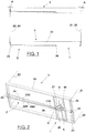
Fig. 1 shows a schematic side view of a suspended bed with a rope system; -
Fig. 2 shows an axonometric view from below of the bed ofFig. 1 , in which the device in question is visible; -
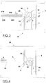
Fig. 3 shows a partial view, from below, of the bed ofFig. 2 , with the device in the position corresponding to the lifted bed; -
Fig. 4 shows a view similar toFig. 3 , with the device in the position corresponding to the lowered bed; -
Figs. 5 and 6 show views similar toFigs. 3 and 4 , relating to a second embodiment of the device; -
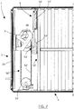
Fig. 7 illustrates a further embodiment of the device of the invention. - In the above-mentioned figures, the device object of the present invention has been indicated as a whole with
reference 1. - The
device 1 is adapted to operate alifting mechanism 2 of a suspendedbed 3, for example of the type mentioned in the introduction, provided in caravans, campers, motor homes, cabin boats and the like. - In a self-known manner, the
lifting mechanism 2 comprises a supportingframe 20 forsaid bed 3, of rectangular shape, and at least fourropes - Each
rope frame 20, to then sequentially engages returningrollers 25, provided in the latter with suitable positions and orientations, for deviating the same rope according to a predetermined path that ends with ahorizontal portion frame 20 and almost parallel to the correspondinghorizontal portions - All the ends of the
horizontal portions common draw hook 26, which is provided to be moved parallel to thesame ropes device 1. - The latter, according to the invention, comprises at least one
pulley 4, which can be rotated by across-member 27 of the supportingframe 20, with substantially vertical rotation axis. - The
pulley 4 coaxially supports, on one side, acogwheel 40, of a suitably inferior diameter. - A
linear drive element 5 is made integral, with an end of its own, to the supportingframe 20 and having associated with the other end of its own, motion transformation means which transform said translation into a synchronous rotation of said cogwheel (40) and pulley (4). More specifically, in the embodiment ofFigs 2 ,3 and 4 the motion transformation means are constituted by arack 50, extended parallel to theelement 5 itself and intended to gear with saidcogwheel 40 to rotate it together with saidpulley 4. - The
device 1 further comprises aflexible cable 6, fixed with one end to saidpulley 4 and wound on the latter with an intermediate portion of its own, for then engaging at least one returningroller 60 arranged downstream of the latter and being fixed, with the remaining end, to said drawhook 26 of theropes - On the rotation of the
pulley 4, therefore, there is a winding or unwinding of theflexible cable 6 on or from it, to which corresponds an actuation of the sameflexible cable 6 for impressing/allowing to saiddraw hook 26 rectilinear excursions, respectively in a first direction T, in which thesame hook 26 and theropes bed 3, and in an opposite direction R, in phase relation with the lowering of thesame bed 3, wherein to thehook 26 and to theropes - In the embodiment shown in
Figs. 2 ,3, 4 , saidlinear drive element 5 is constituted by a gas spring, whose push action is directed to impart a translation of saidrack 50 and, consequently, a synchronous rotation of saidcogwheel 40 andpulley 4 according to a direction concordant with the lifting action of thebed 3, as further specified below. - Specularly, the rotation of the
pulley 4 in the direction in which thebed 3 falls, causes a translation in the opposite direction of therack 50, with the complete re-entry of thestem 50 of thegas spring 5. - As can be easily understood, by varying the ratio between the diameter of the
pulley 4 and that of thecogwheel 40, a greater or smaller linear excursion of theflexible cable 6 is obtained, at the same run of therack 50. - In said embodiment, it is advantageously envisaged to associate to the
linear drive element 5 locking means, suitable for stabilizing at least the raised position of saidbed 3. - Said locking means are of substantially known type and therefore are not shown in detail; by way of example, they can be constituted by a pin, or a pawl, which snaps into position by engaging a hole or a tooth in the
pulley 4 or in therack 50, upon reaching said raised position of saidbed 3. - The release is made by a manual control (also not shown) brought to the side of the
bed 3 by a suitable linkage. - The operation of the
device 1 thus produced, however already partially anticipated by the description above, provides that the raising of thebed 3 is at least facilitated by the pushing action of thegas spring 5, which acting on thepulley 4 through therack 50 and thecogwheel 40 makes it rotate in a first direction K, in which theflexible cable 6 pulls the draw hook 26 (arrow T inFig. 3 ), determining for it a rectilinear excursion proportional to the development of the winding circumference on thepulley 4 and, consequently, equal pull stresses on theropes - The lowering of the
bed 3, vice versa, is at least partly determined by the gravity, so that theropes Fig. 4 ) which, in turn, pull theflexible cable 6; thepulley 4 is therefore driven to rotate in the opposite direction W, causing the return of thestem 50 of thegas spring 5, which is thus recharged. - As a constructive variant, it is expected that the
linear drive element 5 is costituted by a motorized actuator; the operation of thedevice 1 remains substantially unchanged regarding the movement of thepulley 4, of theflexible cable 6, of thedraw hook 26 and of theropes bed 3 become fully automatic and do not require any manual intervention or "help". - For this variant, the presence of said locking means may not be necessary, since the motorized actuator could advantageously be of the self-braking type.
- In an interesting second embodiment of the
device 1, shown inFigs. 5 and 6 , saidlinear drive element 5 comprises agas spring 5A, associated with therack 50 for determining the rotation with same direction of saidcogwheel 40 andpulley 4, similarly to what previously described. Furthermore, aring gear 41 is integral with (or realized into) the outer circumference of saidpulley 4, and it is present a gearedmotor 5B, on whose output shaft is keyed apinion 51 engaged with thering gear 41. - The geared
motor 5B is adapted to cooperate with saidgas spring 5A to determine the rotation in the two directions K, W of thepulley 4, then the ascent and descent of thebed 3 - With this constructive solution, the locking means are in fact incorporated into the drive members, for example if the gear unit is of the endless screw and helical wheel type therefore, as is known, irreversible in the motion direction.
- Every position of the
bed 3 reached, of ascent and descent, even partial, is automatically stabilized. - The interaction between the push of the
gas spring 5A and the power of the gearedmotor 5B can be combined in various ways to make one or the other prevail, nevertheless exploiting the characteristic of said gear unit. - A further embodiment is shown in
Fig. 7 in which it is shown a frame complete with abed 3, but in which, for representation simplicity, it is not shown the system of ropes and return pulleys that are part of thelifting mechanism 2, but which, also in this embodiment, are arranged in a way functionally similar to the one shown in the previous figures. In the present embodiment, thelinear drive element 5 comprises two gas springs, 56', 57', arranged parallel one next to the other, connected in succession one to the other and in which one of them is integral with theframe 20 supporting the bed while the other is integral with the motion transformation means, so as to double the useful stroke of thelinear drive element 5 with the same minimum encumbrance in the drive direction. - In this embodiment the motion transformation means consist of a second cogwheel 51', substantially coplanar to the
cogwheel 40 and having axis rotatably integral with said supportingframe 20 and of a transmission chain, 50', closed in a loop between thecogwheel 40 and the second cogwheel 51'. The second end of thelinear drive element 5 is made integral with chain links, 53', of said transmission chain 50', so that the actuation of thelinear drive element 5 moves the chain links 53' along the closed path of the transmission chain 50' causing thecogwheel 40 to rotate and thereby causing thebed 3 to be lifted or lowered. More specifically, the second cogwheel 51' is arranged such that at least a linear portion, 52', of the transmission chain 50' runs parallel to the actuation direction of thelinear drive element 5. The motion transformation means further comprises a skid, 54', driven to move in a guide rail, 55', integral with theframe 20 and arranged according to the direction of the linear portion 52'. The skid 54' is integral with the second end of thelinear drive element 5 as well as with chain links 53' of said linear portion 52'. Thanks to said construction, the actuation of thelinear drive element 5 moves the skid 54' along the guide rail 55', thus bringing the transmission chain 50' into motion which in turn drives thecogwheel 40 in rotation. - This last embodiment is particularly solid and reliable over time thanks to the possibility of making solid and secure couplings between the various motion transmission components.
- From the above description the peculiar characteristics of the proposed device are clearly clear, in particular regarding its compactness in relation to the width of the vertical excursion allowed to the bed; this advantageous aspect is increasingly evident in comparison with the prior art referred to in the document cited in the introduction.
- The vertical excursion possible for the bed can become very wide, thanks to the amplification effect given by a large diameter pulley, which can be easily adopted without particular complications.
- The technical solution that provides the geared motor in combination with the gas spring is particularly advantageous.
- For all the embodiments described, it is easy to introduce, if not already inherent in the constructive solution itself, means for stabilizing the positions reached by the bed, in order to avoid at least undesirable lowerings, potentially dangerous.
- It is also evident that the constructive solutions described are extremely simple, guaranteeing a low production cost.
Claims (8)
- Suspended bed (3) comprising a lifting mechanism (2) and a device (1) for driving said lifting mechanism, wherein the mechanism (2) comprises a supporting frame (20) to said bed (3), of rectangular shape, and at least four ropes (21, 22, 23, 24), each of which is secured at its top to a fixed structure (A), said at least four ropes (21, 22, 23, 24) extended downward until a corresponding edge of the said supporting frame (20), then to sequentially engage returning rollers (25), provided in the supporting frame (20) to deflect the same ropes (21, 22, 23, 24) according to a predetermined path which ends with a horizontal portion (21H, 22H, 23H, 24H), displaced below the mentioned supporting frame (20) and almost parallel to the corresponding horizontal portions (21H, 22H, 23H, 24H) of the remaining ropes (21, 22, 23, 24), with all the respective ends bound to a common draw hook (26), which is provided to be moved together with the same ropes (21, 22, 23, 24), wherein said device (1) comprises:- at least one pulley (4), rotatably carried by the mentioned supporting frame (20), with a substantially vertical rotation axis;- a cogwheel (40), made coaxially integral to said pulley (4);- a linear drive element (5), integral with one of its ends with said supporting frame (20) and having associated, at the other end thereof, motion transformation means;- a flexible cable (6), bound at one end to said pulley (4) and wound about said pulley (4) with a intermediate portion thereof engaged with at least one returning roller (60) arranged downstream and secured with the remaining end to said draw hook (26) of the ropes (21, 22, 23, 24), so that to the rotation of the pulley (4) and of the cogwheel (40) corresponds a driving of the same flexible cable (6) for imparting / enabling to the mentioned draw hook (26) rectilinear movements, respectively in a first direction, in which the same hook (26) and the ropes (21, 22, 23, 24) are pulled to lift said bed (3), and in an opposite direction, in phase relation with the descent of the same bed (3), in which to the hook (26) and to the ropes (21, 22, 23, 24) is permitted a return stroke, wherein said motion transformation means consist of at least a second cogwheel (51') substantially coplanar to said cogwheel (40) and having an axis rotatably integral with said supporting frame (20) and of a transmission chain (50') closed in a loop between said at least one second cogwheel (51') and said cogwheel (40), said second end of said linear drive element (5) being made integral with chain links (53') of said transmission chain, so that the actuation of said linear drive element (5) moves said chain links (53') along the closed path of said transmission chain (50') bringing said cogwheel (40) into rotation, said second cogwheel (51') being arranged in such a way that at least one linear portion (52') of said transmission chain (50') runs parallel to the motion direction of said linear drive element (5), said motion transformation means comprising a skid (54'), guided to move in a guide rail (55') according to the direction of said linear portion (52'), said skid (54') being integral with said second end of said linear drive element (5) as well as with chain links (53') of said linear portion (52').
- Suspended bed according to claim 1, characterized in that said linear drive element (5) is a linear actuator.
- Suspended bed according to the claim 1, characterized in that said linear drive element (5) is at least a gas spring, which push action is directed to impart a translational motion to said motion transformation means which transform said translational motion into a synchronous rotation of said cogwheel (40) and pulley (4) in a direction concordant with the action of lifting the mentioned bed (3).
- Suspended bed according to the previous claim characterized in that said linear drive element (5) consists of two gas springs (56', 57') arranged parallel to each other, connected in succession to each other and in which one of them is integral to said supporting frame (20) while the other is integral with said motion transformation means, so as to double the useful stroke of said linear drive element (5) with the same minimum encumbrance in the drive direction.
- Suspended bed according to claim 3, characterized in that locking means are associated with said linear drive element (5), provided to stabilize at least the raised position of the said bed (3).
- Suspended bed according to the claim 1, characterized in that said motion transformation means are constituted by a rack (50), extended parallel to the element (5) itself and intended to engage with said cogwheel (40) in order to rotate it together with said pulley (4).
- Suspended bed according to the previous claim, characterized in that said linear drive element (5) comprises: a gas spring (5A), associated to said rack (50) to determine the rotation with same direction of said cogwheel (40) and pulley (4); a ring gear (41) integral with the outer circumference of said pulley (4); a geared motor (5B), on whose output shaft is keyed a pinion (51) meshed with said ring gear (41), with said geared motor (5B) arranged to cooperate with said gas spring (5A) to determine the rotation in the two directions of said pulley (4), then the ascent and descent of the bed (3) as well as to stabilize at least the raised position of the latter.
- Suspended bed according to any of the preceding claims, characterized in that said cogwheel (40) has a diameter lower than that of the mentioned pulley (4).
Applications Claiming Priority (2)
| Application Number | Priority Date | Filing Date | Title |
|---|---|---|---|
| IT102016000127978A IT201600127978A1 (en) | 2016-12-19 | 2016-12-19 | LIFTING DEVICE WITH CABLES FOR BEDS OF RECREATIONAL VEHICLES |
| PCT/IB2017/058146 WO2018116169A1 (en) | 2016-12-19 | 2017-12-19 | Lifting device with ropes for beds in recreational vehicles |
Publications (2)
| Publication Number | Publication Date |
|---|---|
| EP3554890A1 EP3554890A1 (en) | 2019-10-23 |
| EP3554890B1 true EP3554890B1 (en) | 2020-11-04 |
Family
ID=58545111
Family Applications (1)
| Application Number | Title | Priority Date | Filing Date |
|---|---|---|---|
| EP17832810.0A Active EP3554890B1 (en) | 2016-12-19 | 2017-12-19 | Suspended bed |
Country Status (5)
| Country | Link |
|---|---|
| US (1) | US20200017015A1 (en) |
| EP (1) | EP3554890B1 (en) |
| CN (1) | CN110087945A (en) |
| IT (1) | IT201600127978A1 (en) |
| WO (1) | WO2018116169A1 (en) |
Families Citing this family (4)
| Publication number | Priority date | Publication date | Assignee | Title |
|---|---|---|---|---|
| CN111661478B (en) * | 2020-06-05 | 2024-04-12 | 重庆工程职业技术学院 | A cargo tying hook with a function of synchronously storing a hook and a tying rope and a control method thereof |
| CN113103495B (en) * | 2021-05-11 | 2024-03-22 | 丁文龙 | Forming tractor for plastic steel tile processing and plastic steel tile processing technology |
| CN116788133B (en) * | 2022-03-17 | 2026-02-17 | 上海吉田拉链有限公司 | Pulling device for zippers |
| CN115431858B (en) * | 2022-09-13 | 2023-07-18 | 东风柳州汽车有限公司 | Vehicle-mounted folding sleeper and automobile |
Family Cites Families (13)
| Publication number | Priority date | Publication date | Assignee | Title |
|---|---|---|---|---|
| US593445A (en) * | 1897-11-09 | The nor | ||
| JPH061005Y2 (en) * | 1988-06-20 | 1994-01-12 | 三和シヤッター工業株式会社 | Lifting positioning device in lifting bed |
| DE19620796A1 (en) * | 1996-05-23 | 1997-11-27 | Woehr Otto Gmbh | Vehicle parking device |
| US8136181B2 (en) * | 2003-01-27 | 2012-03-20 | Emmett James Roepke | System and method for retractable furniture unit |
| WO2006007522A2 (en) * | 2004-07-01 | 2006-01-19 | Actuant Corporation | In-vehicle lift mechanism |
| KR101398162B1 (en) * | 2012-08-27 | 2014-05-22 | 방경화 | Bed device for Ceiling fixed type lift |
| CN203646848U (en) * | 2014-01-08 | 2014-06-18 | 彭景春 | Mechanical hammock |
| EP2987429B1 (en) * | 2014-08-20 | 2016-09-07 | Alu-Line Metallbearbeitungs GmbH | Vertically movable lifting bed device |
| CN204105389U (en) * | 2014-10-08 | 2015-01-21 | 刘晓萌 | A kind of stealth is in the unsettled bed on roof |
| CN204146697U (en) * | 2014-10-11 | 2015-02-11 | 王先全 | The unsettled bed in a kind of roof |
| JP5902789B1 (en) * | 2014-10-30 | 2016-04-13 | 株式会社室井製作所 | Lifting device and wheelchair transport device using the same |
| CN105852519A (en) * | 2016-04-11 | 2016-08-17 | 浙江大学 | Lifting bed |
| CN106043097B (en) * | 2016-08-04 | 2018-06-15 | 王长振 | For the three-bend multifunctional lifting hammock of caravan |
-
2016
- 2016-12-19 IT IT102016000127978A patent/IT201600127978A1/en unknown
-
2017
- 2017-12-19 CN CN201780078802.6A patent/CN110087945A/en active Pending
- 2017-12-19 WO PCT/IB2017/058146 patent/WO2018116169A1/en not_active Ceased
- 2017-12-19 US US16/470,824 patent/US20200017015A1/en not_active Abandoned
- 2017-12-19 EP EP17832810.0A patent/EP3554890B1/en active Active
Non-Patent Citations (1)
| Title |
|---|
| None * |
Also Published As
| Publication number | Publication date |
|---|---|
| US20200017015A1 (en) | 2020-01-16 |
| EP3554890A1 (en) | 2019-10-23 |
| WO2018116169A1 (en) | 2018-06-28 |
| IT201600127978A1 (en) | 2018-06-19 |
| CN110087945A (en) | 2019-08-02 |
Similar Documents
| Publication | Publication Date | Title |
|---|---|---|
| EP3554890B1 (en) | Suspended bed | |
| US5528948A (en) | Actuating device provided with a pull and resilient return jack | |
| EP3434857B1 (en) | Screen with head rail, bottom rail and middle rail and a first control unit for the middle rail and a second control unit for the bottom rail | |
| US20130299103A1 (en) | Parallel Bar Cording for Movable Rails | |
| EP2050487B1 (en) | Apparatus for carrying a load | |
| CN207847425U (en) | A kind of sliding door that can be locked at any time | |
| EP2385184A1 (en) | Skylight with operator for vertical opening movement | |
| US9255430B2 (en) | Folding door with two or more intrinsically rigid folding shutter elements with alternately noncollapsing or collapsing element edges and actuation device for same | |
| EP2371597A1 (en) | Actuator for covering canvas of top-bodies | |
| US4346929A (en) | Truck with loading platform and body | |
| CA2831949C (en) | Winding apparatus for covering openings in wall portions | |
| WO2025017526A1 (en) | Piece of furniture for a recreational vehicle | |
| HRP20140795T1 (en) | Parking system for motor vehicles | |
| US12419414B2 (en) | Motorized horizontal support system | |
| EP3050749B1 (en) | Device for handling beds | |
| CA2813410A1 (en) | Retractable shelving system | |
| JP6185380B2 (en) | Opening and closing device for open window | |
| EP2509812B1 (en) | Actuation system for covering canvas of top-bodies | |
| JP6598263B2 (en) | Elevating and traversing parking system with charging function | |
| DE102009013628A1 (en) | Portable lifting device for passenger elevator, has telescope structure with deposition platform and crane structure, where telescope structure is displaced horizontally at substructure | |
| US198718A (en) | Improvement in traveling cranes | |
| JP2008013950A (en) | Light control member lifting device for window | |
| CA3161123C (en) | Motorized horizontal support system | |
| EP2455256A1 (en) | Mechanical stop device for adjusting the vertical position of a bed in a recreational vehicle | |
| KR20120052055A (en) | Apparatus for adjusting position of lift |
Legal Events
| Date | Code | Title | Description |
|---|---|---|---|
| STAA | Information on the status of an ep patent application or granted ep patent |
Free format text: STATUS: UNKNOWN |
|
| STAA | Information on the status of an ep patent application or granted ep patent |
Free format text: STATUS: THE INTERNATIONAL PUBLICATION HAS BEEN MADE |
|
| PUAI | Public reference made under article 153(3) epc to a published international application that has entered the european phase |
Free format text: ORIGINAL CODE: 0009012 |
|
| STAA | Information on the status of an ep patent application or granted ep patent |
Free format text: STATUS: REQUEST FOR EXAMINATION WAS MADE |
|
| 17P | Request for examination filed |
Effective date: 20190705 |
|
| AK | Designated contracting states |
Kind code of ref document: A1 Designated state(s): AL AT BE BG CH CY CZ DE DK EE ES FI FR GB GR HR HU IE IS IT LI LT LU LV MC MK MT NL NO PL PT RO RS SE SI SK SM TR |
|
| AX | Request for extension of the european patent |
Extension state: BA ME |
|
| DAV | Request for validation of the european patent (deleted) | ||
| DAX | Request for extension of the european patent (deleted) | ||
| GRAP | Despatch of communication of intention to grant a patent |
Free format text: ORIGINAL CODE: EPIDOSNIGR1 |
|
| STAA | Information on the status of an ep patent application or granted ep patent |
Free format text: STATUS: GRANT OF PATENT IS INTENDED |
|
| INTG | Intention to grant announced |
Effective date: 20200520 |
|
| GRAS | Grant fee paid |
Free format text: ORIGINAL CODE: EPIDOSNIGR3 |
|
| GRAA | (expected) grant |
Free format text: ORIGINAL CODE: 0009210 |
|
| STAA | Information on the status of an ep patent application or granted ep patent |
Free format text: STATUS: THE PATENT HAS BEEN GRANTED |
|
| AK | Designated contracting states |
Kind code of ref document: B1 Designated state(s): AL AT BE BG CH CY CZ DE DK EE ES FI FR GB GR HR HU IE IS IT LI LT LU LV MC MK MT NL NO PL PT RO RS SE SI SK SM TR |
|
| REG | Reference to a national code |
Ref country code: GB Ref legal event code: FG4D |
|
| REG | Reference to a national code |
Ref country code: CH Ref legal event code: EP |
|
| REG | Reference to a national code |
Ref country code: AT Ref legal event code: REF Ref document number: 1330411 Country of ref document: AT Kind code of ref document: T Effective date: 20201115 |
|
| REG | Reference to a national code |
Ref country code: IE Ref legal event code: FG4D |
|
| REG | Reference to a national code |
Ref country code: DE Ref legal event code: R096 Ref document number: 602017027095 Country of ref document: DE |
|
| RAP2 | Party data changed (patent owner data changed or rights of a patent transferred) |
Owner name: LCI ITALY S.R.L. |
|
| REG | Reference to a national code |
Ref country code: DE Ref legal event code: R081 Ref document number: 602017027095 Country of ref document: DE Owner name: LCI ITALY S.R.L., IT Free format text: FORMER OWNER: ST.LA. S.R.L., PONTEDERA, IT |
|
| REG | Reference to a national code |
Ref country code: NL Ref legal event code: MP Effective date: 20201104 |
|
| REG | Reference to a national code |
Ref country code: AT Ref legal event code: MK05 Ref document number: 1330411 Country of ref document: AT Kind code of ref document: T Effective date: 20201104 |
|
| PG25 | Lapsed in a contracting state [announced via postgrant information from national office to epo] |
Ref country code: GR Free format text: LAPSE BECAUSE OF FAILURE TO SUBMIT A TRANSLATION OF THE DESCRIPTION OR TO PAY THE FEE WITHIN THE PRESCRIBED TIME-LIMIT Effective date: 20210205 Ref country code: NO Free format text: LAPSE BECAUSE OF FAILURE TO SUBMIT A TRANSLATION OF THE DESCRIPTION OR TO PAY THE FEE WITHIN THE PRESCRIBED TIME-LIMIT Effective date: 20210204 Ref country code: PT Free format text: LAPSE BECAUSE OF FAILURE TO SUBMIT A TRANSLATION OF THE DESCRIPTION OR TO PAY THE FEE WITHIN THE PRESCRIBED TIME-LIMIT Effective date: 20210304 Ref country code: RS Free format text: LAPSE BECAUSE OF FAILURE TO SUBMIT A TRANSLATION OF THE DESCRIPTION OR TO PAY THE FEE WITHIN THE PRESCRIBED TIME-LIMIT Effective date: 20201104 Ref country code: FI Free format text: LAPSE BECAUSE OF FAILURE TO SUBMIT A TRANSLATION OF THE DESCRIPTION OR TO PAY THE FEE WITHIN THE PRESCRIBED TIME-LIMIT Effective date: 20201104 |
|
| PG25 | Lapsed in a contracting state [announced via postgrant information from national office to epo] |
Ref country code: BG Free format text: LAPSE BECAUSE OF FAILURE TO SUBMIT A TRANSLATION OF THE DESCRIPTION OR TO PAY THE FEE WITHIN THE PRESCRIBED TIME-LIMIT Effective date: 20210204 Ref country code: SE Free format text: LAPSE BECAUSE OF FAILURE TO SUBMIT A TRANSLATION OF THE DESCRIPTION OR TO PAY THE FEE WITHIN THE PRESCRIBED TIME-LIMIT Effective date: 20201104 Ref country code: LV Free format text: LAPSE BECAUSE OF FAILURE TO SUBMIT A TRANSLATION OF THE DESCRIPTION OR TO PAY THE FEE WITHIN THE PRESCRIBED TIME-LIMIT Effective date: 20201104 Ref country code: IS Free format text: LAPSE BECAUSE OF FAILURE TO SUBMIT A TRANSLATION OF THE DESCRIPTION OR TO PAY THE FEE WITHIN THE PRESCRIBED TIME-LIMIT Effective date: 20210304 Ref country code: PL Free format text: LAPSE BECAUSE OF FAILURE TO SUBMIT A TRANSLATION OF THE DESCRIPTION OR TO PAY THE FEE WITHIN THE PRESCRIBED TIME-LIMIT Effective date: 20201104 Ref country code: AT Free format text: LAPSE BECAUSE OF FAILURE TO SUBMIT A TRANSLATION OF THE DESCRIPTION OR TO PAY THE FEE WITHIN THE PRESCRIBED TIME-LIMIT Effective date: 20201104 Ref country code: ES Free format text: LAPSE BECAUSE OF FAILURE TO SUBMIT A TRANSLATION OF THE DESCRIPTION OR TO PAY THE FEE WITHIN THE PRESCRIBED TIME-LIMIT Effective date: 20201104 |
|
| REG | Reference to a national code |
Ref country code: LT Ref legal event code: MG9D |
|
| PG25 | Lapsed in a contracting state [announced via postgrant information from national office to epo] |
Ref country code: HR Free format text: LAPSE BECAUSE OF FAILURE TO SUBMIT A TRANSLATION OF THE DESCRIPTION OR TO PAY THE FEE WITHIN THE PRESCRIBED TIME-LIMIT Effective date: 20201104 |
|
| PG25 | Lapsed in a contracting state [announced via postgrant information from national office to epo] |
Ref country code: SM Free format text: LAPSE BECAUSE OF FAILURE TO SUBMIT A TRANSLATION OF THE DESCRIPTION OR TO PAY THE FEE WITHIN THE PRESCRIBED TIME-LIMIT Effective date: 20201104 Ref country code: EE Free format text: LAPSE BECAUSE OF FAILURE TO SUBMIT A TRANSLATION OF THE DESCRIPTION OR TO PAY THE FEE WITHIN THE PRESCRIBED TIME-LIMIT Effective date: 20201104 Ref country code: CZ Free format text: LAPSE BECAUSE OF FAILURE TO SUBMIT A TRANSLATION OF THE DESCRIPTION OR TO PAY THE FEE WITHIN THE PRESCRIBED TIME-LIMIT Effective date: 20201104 Ref country code: LT Free format text: LAPSE BECAUSE OF FAILURE TO SUBMIT A TRANSLATION OF THE DESCRIPTION OR TO PAY THE FEE WITHIN THE PRESCRIBED TIME-LIMIT Effective date: 20201104 Ref country code: RO Free format text: LAPSE BECAUSE OF FAILURE TO SUBMIT A TRANSLATION OF THE DESCRIPTION OR TO PAY THE FEE WITHIN THE PRESCRIBED TIME-LIMIT Effective date: 20201104 Ref country code: SK Free format text: LAPSE BECAUSE OF FAILURE TO SUBMIT A TRANSLATION OF THE DESCRIPTION OR TO PAY THE FEE WITHIN THE PRESCRIBED TIME-LIMIT Effective date: 20201104 |
|
| REG | Reference to a national code |
Ref country code: CH Ref legal event code: PL |
|
| REG | Reference to a national code |
Ref country code: DE Ref legal event code: R097 Ref document number: 602017027095 Country of ref document: DE |
|
| PG25 | Lapsed in a contracting state [announced via postgrant information from national office to epo] |
Ref country code: MC Free format text: LAPSE BECAUSE OF FAILURE TO SUBMIT A TRANSLATION OF THE DESCRIPTION OR TO PAY THE FEE WITHIN THE PRESCRIBED TIME-LIMIT Effective date: 20201104 Ref country code: DK Free format text: LAPSE BECAUSE OF FAILURE TO SUBMIT A TRANSLATION OF THE DESCRIPTION OR TO PAY THE FEE WITHIN THE PRESCRIBED TIME-LIMIT Effective date: 20201104 |
|
| REG | Reference to a national code |
Ref country code: BE Ref legal event code: MM Effective date: 20201231 |
|
| PLBE | No opposition filed within time limit |
Free format text: ORIGINAL CODE: 0009261 |
|
| STAA | Information on the status of an ep patent application or granted ep patent |
Free format text: STATUS: NO OPPOSITION FILED WITHIN TIME LIMIT |
|
| 26N | No opposition filed |
Effective date: 20210805 |
|
| PG25 | Lapsed in a contracting state [announced via postgrant information from national office to epo] |
Ref country code: LU Free format text: LAPSE BECAUSE OF NON-PAYMENT OF DUE FEES Effective date: 20201219 Ref country code: NL Free format text: LAPSE BECAUSE OF FAILURE TO SUBMIT A TRANSLATION OF THE DESCRIPTION OR TO PAY THE FEE WITHIN THE PRESCRIBED TIME-LIMIT Effective date: 20201104 Ref country code: AL Free format text: LAPSE BECAUSE OF FAILURE TO SUBMIT A TRANSLATION OF THE DESCRIPTION OR TO PAY THE FEE WITHIN THE PRESCRIBED TIME-LIMIT Effective date: 20201104 Ref country code: IE Free format text: LAPSE BECAUSE OF NON-PAYMENT OF DUE FEES Effective date: 20201219 |
|
| REG | Reference to a national code |
Ref country code: GB Ref legal event code: 732E Free format text: REGISTERED BETWEEN 20211028 AND 20211103 |
|
| PG25 | Lapsed in a contracting state [announced via postgrant information from national office to epo] |
Ref country code: LI Free format text: LAPSE BECAUSE OF NON-PAYMENT OF DUE FEES Effective date: 20201231 Ref country code: SI Free format text: LAPSE BECAUSE OF FAILURE TO SUBMIT A TRANSLATION OF THE DESCRIPTION OR TO PAY THE FEE WITHIN THE PRESCRIBED TIME-LIMIT Effective date: 20201104 Ref country code: CH Free format text: LAPSE BECAUSE OF NON-PAYMENT OF DUE FEES Effective date: 20201231 |
|
| PG25 | Lapsed in a contracting state [announced via postgrant information from national office to epo] |
Ref country code: IS Free format text: LAPSE BECAUSE OF FAILURE TO SUBMIT A TRANSLATION OF THE DESCRIPTION OR TO PAY THE FEE WITHIN THE PRESCRIBED TIME-LIMIT Effective date: 20210304 Ref country code: TR Free format text: LAPSE BECAUSE OF FAILURE TO SUBMIT A TRANSLATION OF THE DESCRIPTION OR TO PAY THE FEE WITHIN THE PRESCRIBED TIME-LIMIT Effective date: 20201104 Ref country code: MT Free format text: LAPSE BECAUSE OF FAILURE TO SUBMIT A TRANSLATION OF THE DESCRIPTION OR TO PAY THE FEE WITHIN THE PRESCRIBED TIME-LIMIT Effective date: 20201104 Ref country code: CY Free format text: LAPSE BECAUSE OF FAILURE TO SUBMIT A TRANSLATION OF THE DESCRIPTION OR TO PAY THE FEE WITHIN THE PRESCRIBED TIME-LIMIT Effective date: 20201104 |
|
| PG25 | Lapsed in a contracting state [announced via postgrant information from national office to epo] |
Ref country code: MK Free format text: LAPSE BECAUSE OF FAILURE TO SUBMIT A TRANSLATION OF THE DESCRIPTION OR TO PAY THE FEE WITHIN THE PRESCRIBED TIME-LIMIT Effective date: 20201104 |
|
| PG25 | Lapsed in a contracting state [announced via postgrant information from national office to epo] |
Ref country code: BE Free format text: LAPSE BECAUSE OF NON-PAYMENT OF DUE FEES Effective date: 20201231 |
|
| PGFP | Annual fee paid to national office [announced via postgrant information from national office to epo] |
Ref country code: GB Payment date: 20231219 Year of fee payment: 7 |
|
| PGFP | Annual fee paid to national office [announced via postgrant information from national office to epo] |
Ref country code: IT Payment date: 20231215 Year of fee payment: 7 Ref country code: FR Payment date: 20231226 Year of fee payment: 7 |
|
| PGFP | Annual fee paid to national office [announced via postgrant information from national office to epo] |
Ref country code: DE Payment date: 20241218 Year of fee payment: 8 |
|
| GBPC | Gb: european patent ceased through non-payment of renewal fee |
Effective date: 20241219 |
|
| PG25 | Lapsed in a contracting state [announced via postgrant information from national office to epo] |
Ref country code: IT Free format text: LAPSE BECAUSE OF NON-PAYMENT OF DUE FEES Effective date: 20241219 |
|
| PG25 | Lapsed in a contracting state [announced via postgrant information from national office to epo] |
Ref country code: GB Free format text: LAPSE BECAUSE OF NON-PAYMENT OF DUE FEES Effective date: 20241219 |
|
| PG25 | Lapsed in a contracting state [announced via postgrant information from national office to epo] |
Ref country code: FR Free format text: LAPSE BECAUSE OF NON-PAYMENT OF DUE FEES Effective date: 20241231 |