EP3554793B1 - Production d'une interface liquide continue présentant un suivi et une rétroaction de force - Google Patents
Production d'une interface liquide continue présentant un suivi et une rétroaction de force Download PDFInfo
- Publication number
- EP3554793B1 EP3554793B1 EP17812215.6A EP17812215A EP3554793B1 EP 3554793 B1 EP3554793 B1 EP 3554793B1 EP 17812215 A EP17812215 A EP 17812215A EP 3554793 B1 EP3554793 B1 EP 3554793B1
- Authority
- EP
- European Patent Office
- Prior art keywords
- dimensional object
- carrier
- optically transparent
- transparent member
- growing
- Prior art date
- Legal status (The legal status is an assumption and is not a legal conclusion. Google has not performed a legal analysis and makes no representation as to the accuracy of the status listed.)
- Active
Links
Images


Classifications
-
- B—PERFORMING OPERATIONS; TRANSPORTING
- B29—WORKING OF PLASTICS; WORKING OF SUBSTANCES IN A PLASTIC STATE IN GENERAL
- B29C—SHAPING OR JOINING OF PLASTICS; SHAPING OF MATERIAL IN A PLASTIC STATE, NOT OTHERWISE PROVIDED FOR; AFTER-TREATMENT OF THE SHAPED PRODUCTS, e.g. REPAIRING
- B29C64/00—Additive manufacturing, i.e. manufacturing of three-dimensional [3D] objects by additive deposition, additive agglomeration or additive layering, e.g. by 3D printing, stereolithography or selective laser sintering
- B29C64/10—Processes of additive manufacturing
- B29C64/106—Processes of additive manufacturing using only liquids or viscous materials, e.g. depositing a continuous bead of viscous material
- B29C64/124—Processes of additive manufacturing using only liquids or viscous materials, e.g. depositing a continuous bead of viscous material using layers of liquid which are selectively solidified
- B29C64/129—Processes of additive manufacturing using only liquids or viscous materials, e.g. depositing a continuous bead of viscous material using layers of liquid which are selectively solidified characterised by the energy source therefor, e.g. by global irradiation combined with a mask
- B29C64/135—Processes of additive manufacturing using only liquids or viscous materials, e.g. depositing a continuous bead of viscous material using layers of liquid which are selectively solidified characterised by the energy source therefor, e.g. by global irradiation combined with a mask the energy source being concentrated, e.g. scanning lasers or focused light sources
-
- B—PERFORMING OPERATIONS; TRANSPORTING
- B29—WORKING OF PLASTICS; WORKING OF SUBSTANCES IN A PLASTIC STATE IN GENERAL
- B29C—SHAPING OR JOINING OF PLASTICS; SHAPING OF MATERIAL IN A PLASTIC STATE, NOT OTHERWISE PROVIDED FOR; AFTER-TREATMENT OF THE SHAPED PRODUCTS, e.g. REPAIRING
- B29C64/00—Additive manufacturing, i.e. manufacturing of three-dimensional [3D] objects by additive deposition, additive agglomeration or additive layering, e.g. by 3D printing, stereolithography or selective laser sintering
- B29C64/20—Apparatus for additive manufacturing; Details thereof or accessories therefor
- B29C64/245—Platforms or substrates
-
- B—PERFORMING OPERATIONS; TRANSPORTING
- B29—WORKING OF PLASTICS; WORKING OF SUBSTANCES IN A PLASTIC STATE IN GENERAL
- B29C—SHAPING OR JOINING OF PLASTICS; SHAPING OF MATERIAL IN A PLASTIC STATE, NOT OTHERWISE PROVIDED FOR; AFTER-TREATMENT OF THE SHAPED PRODUCTS, e.g. REPAIRING
- B29C64/00—Additive manufacturing, i.e. manufacturing of three-dimensional [3D] objects by additive deposition, additive agglomeration or additive layering, e.g. by 3D printing, stereolithography or selective laser sintering
- B29C64/20—Apparatus for additive manufacturing; Details thereof or accessories therefor
- B29C64/264—Arrangements for irradiation
- B29C64/277—Arrangements for irradiation using multiple radiation means, e.g. micromirrors or multiple light-emitting diodes [LED]
-
- B—PERFORMING OPERATIONS; TRANSPORTING
- B29—WORKING OF PLASTICS; WORKING OF SUBSTANCES IN A PLASTIC STATE IN GENERAL
- B29C—SHAPING OR JOINING OF PLASTICS; SHAPING OF MATERIAL IN A PLASTIC STATE, NOT OTHERWISE PROVIDED FOR; AFTER-TREATMENT OF THE SHAPED PRODUCTS, e.g. REPAIRING
- B29C64/00—Additive manufacturing, i.e. manufacturing of three-dimensional [3D] objects by additive deposition, additive agglomeration or additive layering, e.g. by 3D printing, stereolithography or selective laser sintering
- B29C64/30—Auxiliary operations or equipment
- B29C64/386—Data acquisition or data processing for additive manufacturing
- B29C64/393—Data acquisition or data processing for additive manufacturing for controlling or regulating additive manufacturing processes
-
- B—PERFORMING OPERATIONS; TRANSPORTING
- B33—ADDITIVE MANUFACTURING TECHNOLOGY
- B33Y—ADDITIVE MANUFACTURING, i.e. MANUFACTURING OF THREE-DIMENSIONAL [3D] OBJECTS BY ADDITIVE DEPOSITION, ADDITIVE AGGLOMERATION OR ADDITIVE LAYERING, e.g. BY 3D PRINTING, STEREOLITHOGRAPHY OR SELECTIVE LASER SINTERING
- B33Y30/00—Apparatus for additive manufacturing; Details thereof or accessories therefor
-
- B—PERFORMING OPERATIONS; TRANSPORTING
- B33—ADDITIVE MANUFACTURING TECHNOLOGY
- B33Y—ADDITIVE MANUFACTURING, i.e. MANUFACTURING OF THREE-DIMENSIONAL [3D] OBJECTS BY ADDITIVE DEPOSITION, ADDITIVE AGGLOMERATION OR ADDITIVE LAYERING, e.g. BY 3D PRINTING, STEREOLITHOGRAPHY OR SELECTIVE LASER SINTERING
- B33Y50/00—Data acquisition or data processing for additive manufacturing
- B33Y50/02—Data acquisition or data processing for additive manufacturing for controlling or regulating additive manufacturing processes
-
- G—PHYSICS
- G03—PHOTOGRAPHY; CINEMATOGRAPHY; ANALOGOUS TECHNIQUES USING WAVES OTHER THAN OPTICAL WAVES; ELECTROGRAPHY; HOLOGRAPHY
- G03F—PHOTOMECHANICAL PRODUCTION OF TEXTURED OR PATTERNED SURFACES, e.g. FOR PRINTING, FOR PROCESSING OF SEMICONDUCTOR DEVICES; MATERIALS THEREFOR; ORIGINALS THEREFOR; APPARATUS SPECIALLY ADAPTED THEREFOR
- G03F7/00—Photomechanical, e.g. photolithographic, production of textured or patterned surfaces, e.g. printing surfaces; Materials therefor, e.g. comprising photoresists; Apparatus specially adapted therefor
- G03F7/70—Microphotolithographic exposure; Apparatus therefor
- G03F7/70416—2.5D lithography
-
- B—PERFORMING OPERATIONS; TRANSPORTING
- B29—WORKING OF PLASTICS; WORKING OF SUBSTANCES IN A PLASTIC STATE IN GENERAL
- B29K—INDEXING SCHEME ASSOCIATED WITH SUBCLASSES B29B, B29C OR B29D, RELATING TO MOULDING MATERIALS OR TO MATERIALS FOR MOULDS, REINFORCEMENTS, FILLERS OR PREFORMED PARTS, e.g. INSERTS
- B29K2105/00—Condition, form or state of moulded material or of the material to be shaped
- B29K2105/0002—Condition, form or state of moulded material or of the material to be shaped monomers or prepolymers
-
- B—PERFORMING OPERATIONS; TRANSPORTING
- B29—WORKING OF PLASTICS; WORKING OF SUBSTANCES IN A PLASTIC STATE IN GENERAL
- B29K—INDEXING SCHEME ASSOCIATED WITH SUBCLASSES B29B, B29C OR B29D, RELATING TO MOULDING MATERIALS OR TO MATERIALS FOR MOULDS, REINFORCEMENTS, FILLERS OR PREFORMED PARTS, e.g. INSERTS
- B29K2105/00—Condition, form or state of moulded material or of the material to be shaped
- B29K2105/0058—Liquid or visquous
-
- B—PERFORMING OPERATIONS; TRANSPORTING
- B33—ADDITIVE MANUFACTURING TECHNOLOGY
- B33Y—ADDITIVE MANUFACTURING, i.e. MANUFACTURING OF THREE-DIMENSIONAL [3D] OBJECTS BY ADDITIVE DEPOSITION, ADDITIVE AGGLOMERATION OR ADDITIVE LAYERING, e.g. BY 3D PRINTING, STEREOLITHOGRAPHY OR SELECTIVE LASER SINTERING
- B33Y10/00—Processes of additive manufacturing
Definitions
- the present invention concerns stereolithography methods and apparatus, particularly those for carrying out continuous liquid interface production.
- CLIP is the speed by which objects can be made.
- Another advantage of CLIP is the diversity of (generally viscous) polymerizable liquids which can be used in the process, such as the "dual cure" resins described in J. Rolland et al., US Patent No. 9,453,142 (and others).
- the intermediate three-dimensional objects formed by such resins are - due to the inherent flexibility of the material- themselves flexible rather than stiff.
- the intermediate may be relatively stiff during early production of the object, but as production progress the object may, overall, become increasingly flexible (or "compliant").
- the compliant object being produced may be unable to overcome fluid adhesion of the object to the build surface and allow fluid flow into the build region (particularly during step-wise or reciprocal modes of operation).
- WO 2016/140891 discloses a method of forming the body portion of a three-dimensional object from a polymerizable liquid by a process including advancing a carrier for the object away from a build surface while irradiating a build region between the carrier and build surface in a pattern of advancing and irradiating defined by an operating mode.
- the body portion has a plurality of contiguous segments, with the irradiating carried out in sequentially presented slices of exposure.
- Each slice having a pattern that corresponds to a segment of said body portion.
- Each pattern includes regions of greater irradiation and regions of lesser irradiation (e.g., within the perimeter of each pattern).
- the method includes consecutively changing, for at least a portion of the forming of said three-dimensional object, the pattern between consecutive slices in a sequence of sequentially presented patterns of exposure that facilitates the flow of the polymerizable liquid to the build surface.
- a first aspect of the invention is a method of making a three-dimensional object, which is carried out by: (a) providing a carrier and an optically transparent member having a build surface, the carrier and the build surface defining a build region therebetween, the optically transparent member carrying a polymerizable liquid; (b) advancing the carrier and the optically transparent member away from one another to draw the polymerizable liquid into the build region; then (c) optionally, partially retracting the carrier and the optically transparent member back towards one another; and then (d) irradiating the build region with light to form a growing three-dimensional object from the polymerizable liquid; and then (e) cyclically repeating steps (b) to (d) while maintaining a continuous liquid interface between the growing three-dimensional object and the optically transparent member until at least a portion of the three-dimensional object is formed, while during at least some of the cyclically repeatings: (i) monitoring a transient increase in tension between the carrier and the build surface through the
- the method further includes, during at least some of the cyclically repeatings: (iii) monitoring a transient increase in compression between the carrier and the build surface through the growing three dimensional object during the partially retracting step (c) ; and then, when the transient increase in compression has substantially subsided, (iv) initiating the irradiating step (d).
- a further aspect of the invention is a method of making a three-dimensional object, which is carried out by: (a) providing a carrier and an optically transparent member having a build surface, the carrier and the build surface defining a build region therebetween, the optically transparent member carrying a polymerizable liquid; (b) advancing the carrier and the optically transparent member away from one another to draw the polymerizable liquid into the build region; then (c) partially retracting the carrier and the optically transparent member back towards one another; and then (d) irradiating the build region with light to form a growing three-dimensional object from the polymerizable liquid; and then (e) cyclically repeating steps (b) to (d) while maintaining a continuous liquid interface between the growing three-dimensional object and the optically transparent member until at least a portion of the three-dimensional object is formed, while during at least some of the cyclically repeatings: (i) optionally, monitoring a transient increase in tension between the carrier and the build surface through the growing three-dimensional object during the advancing
- At least a portion of the three-dimensional object is formed while (f) continuously advancing the carrier and the optically transparent member away from one another and (g) intermittently or continuously irradiating the build region to form the growing three-dimensional object, while maintaining the continuous liquid interface.
- At least a portion of the growing three-dimensional object is flexible (due to flexibility of the solidified material, the geometry of the object, or a combination thereof).
- At least a portion (e.g., a major portion) of the object is in the form of a lattice or mesh.
- the polymerizable liquid is viscous at room temperature (e.g., 25 degrees Centigrade) (e.g., has a viscosity of at least 200, 300, 1,000, or 2,000 Centipoise, or more, at room temperature).
- the optically transparent member comprises a semipermeable member (e.g., a fluoropolymer), the advancing, partially retracting when present, irradiating, and/or cyclically repeating steps are carried out while also concurrently:
- a semipermeable member e.g., a fluoropolymer
- the three-dimensional object is fabricated at a speed of at least 1 or 10 millimeters per hour, to 1,000 or 10,000 millimeters per hour, or more.
- a further aspect of the invention is an apparatus useful for making a three-dimensional object from a polymerizable liquid, which apparatus includes: (a) a carrier on which a three-dimensional object can be made; (b) an optically transparent member having a build surface operatively associated with the carrier, the carrier and the build surface defining a build region therebetween, the optically transparent member configured for carrying a polymerizable liquid; (c) an elevator assembly operatively associated with the carrier and/or the optically transparent member, the elevator assembly configured for advancing the carrier and the optically transparent member away from one another to draw the polymerizable liquid into the build region; (d) a light engine operatively associated with the optically transparent member and positioned to irradiate the build region with light to form a growing three-dimensional object from the polymerizable liquid; (e) a force sensor operatively associated with the carrier and/or the optically transparent member and configured to monitor a transient increase in tension and/or a transient increase in compression between the carrier and the build surface through
- the optically transparent member comprises a semipermeable member (e.g., a fluoropolymer).
- the light engine comprises a light source (e.g., a laser) in combination with a patterning array (e.g., a liquid crystal display array or a digital micromirror array).
- the force sensor comprises a strain gauge.
- the step of monitoring a transient increase in tension can be carried out by: (a) monitoring absolute force, (b) monitoring rate of change of force, or (c) monitoring both absolute force and rate of change of force in combination with one another.
- (b) or (c) are preferred, to reduce the influence of slow drift of zero, as discussed below.
- the device may otherwise be oriented (rotated 90 degrees or at other orientations) and the spatially relative descriptors used herein interpreted accordingly.
- the terms “upwardly,” “downwardly,” “vertical,” “horizontal” and the like are used herein for the purpose of explanation only, unless specifically indicated otherwise.
- first, second, etc. may be used herein to describe various elements, components, regions, layers and/or sections, these elements, components, regions, layers and/or sections should not be limited by these terms. Rather, these terms are only used to distinguish one element, component, region, layer and/or section, from another element, component, region, layer and/or section. Thus, a first element, component, region, layer or section discussed herein could be termed a second element, component, region, layer or section without departing from the teachings of the present invention.
- the sequence of operations (or steps) is not limited to the order presented in the claims or figures unless specifically indicated otherwise.
- Dual cure polymerizable liquids useful for CLIP are known and described in, for example, J. Rolland et al., PCT Applications PCT/US2015/036893 (see also US Patent Application Pub. No. US 2016/0136889 ), PCT/US2015/036902 (see also US Patent Application Pub. No. US 2016/0137838 ), PCT/US2015/036924 (see also US Patent Application Pub. No. US 2016/016077 ), and PCT/US2015/036946 (see also US Patent No. 9453,142 ).
- Figure 1 schematically illustrates an apparatus useful for carrying out the present invention.
- the larger upward arrow indicates the dominant direction of upward movement during both stepped and reciprocal (or “pumped") modes of production.
- the dashed arrow indicates the lesser downward movement during reciprocal mode.
- the apparatus includes a light engine 11, a window (or “build plate”) 12, a controller 13, and elevator and drive assembly 14.
- a carrier platform (or “carrier plate”) 15 is mounted to the elevator and drive assembly as in conventional apparatus, but with a force sensor 16 operatively associated therewith.
- a polymerizable liquid 21 is provided on top of the window 12.
- the window 12 may be impermeable or semipermeable to an inhibitor of polymerization (e.g . oxygen), depending on which particular approach for carrying out continuous liquid interface production is employed.
- the window comprises a fluoropolymer, in accordance with known techniques.
- a growing three-dimensional object 31 is shown being formed between the carrier platform 15 (to which it is adhered) and the polymerizable liquid 21, with a continuous liquid interface 22 between the polymerizable liquid 21 and the object 31.
- Regions of higher stiffness (rigid regions) 32 and regions of lower stiffness (flexible regions) 33 on the growing object are indicated.
- the flexible regions are those highly cantilevered and formed later in the process, but in other embodiments (e.g ., highly meshed objects and/or objects formed by resins which are inherently flexible when solidified) the entire object may be flexible.
- Any suitable light engine 11 including any of a variety of light sources and/or patterning elements, may be used, including lasers (e.g ., scanning lasers as in traditional stereolithography), liquid crystal display (LCD) panels, digital micromirror displays (DMDs), etc.
- lasers e.g ., scanning lasers as in traditional stereolithography
- LCD liquid crystal display
- DMDs digital micromirror displays
- a single light engine may be used, or a tiled set of light engines may be used, depending on the size of the window 12 and the desired resolution.
- advancing away is accomplished by lifting the carrier on the elevator
- advancing away and partially retracting may be achieved by providing fixed or static carrier, and by mounting the window and light engine on an elevator beneath the same, which can then be lowered.
- Any suitable device may be used as force sensor 16. Examples include, but are not limited to, mechanical tactile sensors, capacitive force sensors, metal strain gauges, semiconductor strain gauges, conductive elastomers, carbon felt and carbon fiber sensors, piezoelectric force sensors, pyroelectric force sensors, optical force sensors, magnetic force sensors, ulotrasonic force sensors, electrochemical force sensors, etc., including combinations thereof. See, e.g., Matthias Fassler, Force Sensing Technologies (Swiss Federal Institute of Technology Zurich, Spring Term 2010 ).
- One suitable example is the Omega LCM202-1KN Miniature Metric Universal Load Cell, available from Omega Engineering, Inc. (800 Connecticut Ave., Suite 5N01, Norwalk, Connecticut 06854 USA).
- the force sensor may include multiple force sensors providing an averaged output (e.g ., sandwiched between a compression plate to equalize load), and/or may include multiple force sensors providing independent data from multiple regions of the carrier.
- force sensing can be carried out by sensing motor current or torque, or any other direct or indirect measure of force.
- FIG. 2-7 Further details of structuring a non-limiting example of an apparatus of the invention to carry out the methods described herein are given in Figures 2-7 .
- a master system controller which may be local or remote, e.g ., cloud-based
- the entire control protocols could alternatively be implemented by the master system controller, or by a local controller.
- the force sensor 16 which is an analog device, is sampled digitally by the microcontroller with an Analog-to-Digital Converter (ADC; 13a ) and the information stored in the micro controller memory 13b.
- ADC Analog-to-Digital Converter
- the micro controller preferably maintains a constant sampling rate with the ADC and analog device.
- the micro controller handles all moving, waiting, and light engine functions. Without force feedback (as may be used in combination with force feedback in the present invention), a pre-calculated list of commands is given to the micro controller from a higher level system controller. With force feedback, the micro controller can be instructed to move_and_wait_with_feedback instead of using a fixed pre-calculated wait command. Any logic language can be used to code the micro controller, including but not limited to C/C++.
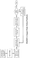
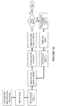
- Figure 3 illustrates further components (or operations) implemented in (or by) the micro-controller.
- the higher level system controller advises the micro controller to move, wait, and monitor the force sensor for triggers. Negative forces are described in the figures as “Tension;” Positive forces are described in the figures as “Compression.”
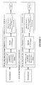
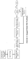
- Figure 4 illustrates stepped control elements of one embodiment of an apparatus of the invention, but without force feedback implemented
- Figure 5 illustrates stepped control elements of the embodiment of Figure 4 , but with force feedback now implemented.
- all cycles in the production of an object may utilize force feedback, or some cycles may forgo force feedback (e.g., for production of an early segment of the object, or for production of a portion with a highly predictable behavior).
- Figure 6 illustrates reciprocal control elements of one embodiment of an apparatus of the invention, but without force feedback implemented
- Figure 7 illustrates reciprocal control elements of the embodiment of Figure 6 , but with force feedback now implemented.
- steps of various embodiments may generally include:
- Times and distances given above are not critical, and are for illustrative purposes only. Specific times and distances will depend upon factors such as object geometry, irradiation wavelength and intensity, object resolution requirements, resin properties (including but not limited to photoinitiator type and density, resin viscosity and polymerized resin properties following irradiation), operating temperature, etc., and can be optimized by those skilled in the art. "Substantially subsided” when referring to transient increases (or decreases) in tension (or compression) generally means within five, ten, or twenty percent of the immediately prior tension or compression. In general, the overall or average speed of fabricating the object, or relevant portion thereof, is at least 1 or 10 millimeters per hour, up to 1,000 or 10,000 millimeters per hour, or more.
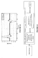
- Figure 8 illustrates a stepped mode of operation of continuous liquid interface production (CLIP), with force monitoring, but without feedback
- Figure 9 illustrates substantially the same mode of operation, but this time with force feedback utilized to initiate the next exposure or irriadiation step during the cyclical repeating of steps.
- the upward arrow indicates the approximate time and direction of movement of the carrier during the advancing step. Note the reduction in time to complete three cycles in Figure 9 as compared to Figure 8 .
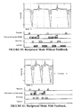
- Figure 10 illustrates a reciprocal mode of operation of CLIP, with force monitoring, but without feedback.
- Figure 11 illustrates the reciprocal mode of operation of CLIP of Figure 10 , but with force feedback implemented (for both tension and compression) to initiate, first, the partially retracting step following each advancing step, and second, the irradiating step following each partially retractacting step.
- the larger upward arrow indicates the approximate time and dominant upward direction of movement of the carrier during the advancing step
- the downward arrow indicates the approximate time and lesser downward movement of the carrier during the partial retracting step. Note the reduction in time to complete three cycles in Figure 11 as compared to Figure 10 .
- a benefit of force sensor feedback is that it enables more efficient printing of elastic objects.
- the stiffness or elasticity of the object being made, or portions thereof need not be known.
- the object merely needs to be sufficiently stiff to (a) withstand the force of production without ripping or fracturing the part, and (b) overcome fluid forces of the resin to reach the desired slice height for each exposure or irradiation.
- a solution may be a complicated and difficult to validate finite element analysis (FEA) model that simulates stiffness, deformation, and adhesion forces, and the actual distance or height required to advance the carrier to overcome adhesion forces (i.e., to "pump" resin into the build zone).
- FEA finite element analysis
- the result of such an approach would typically be conservative, because such simulations are hard to perfect, particularly when process input data is not consistent.
- the methods described herein allow for a more aggressive approach to reducing the amount of time otherwise wasted during each exposure cycle.
- a slow drift of zero when absolute force is measured, there can be a slow drift of zero (lack of tension or compression) over time. Without wishing to be bound to any particular theory, this can result from, for example, the addition of weight to the carrier platform as additional resin is polymerized thereto, buoyancy force changes as the part builds in the Z vertical) direction, electronic sensor nonlinearities, etc. While drift of zero can be tracked by a variety of techniques, a solution is to utilize force rate of change (equivalent to slope, see Figure 12 ) to track force, as shown in Figures 13-14 . Again, functions can be implemented in a microcontroller, with a higher level system controller advising the microcontroller to move, wait, monitor the force sensor for triggers, and the like.
Landscapes
- Engineering & Computer Science (AREA)
- Chemical & Material Sciences (AREA)
- Materials Engineering (AREA)
- Physics & Mathematics (AREA)
- Manufacturing & Machinery (AREA)
- Optics & Photonics (AREA)
- Mechanical Engineering (AREA)
- Health & Medical Sciences (AREA)
- Toxicology (AREA)
- General Physics & Mathematics (AREA)
- Microelectronics & Electronic Packaging (AREA)
Claims (21)
- Procédé de fabrication d'un objet tridimensionnel, comprenant les étapes de :(a) fourniture d'un support (15) et d'un élément optiquement transparent (12) ayant une surface de construction, ledit support (15) et ladite surface de construction définissant une zone de construction entre eux, ledit élément optiquement transparent (12) portant un liquide polymérisable (21) ;(b) avancement dudit support (15) et dudit élément optiquement transparent (12) en éloignement l'un de l'autre pour attirer ledit liquide polymérisable (21) dans ladite zone de construction ; puis(c) facultativement, rétraction partielle dudit support (15) et dudit élément optiquement transparent (12) pour les ramener l'un vers l'autre ; et ensuite(d) irradiation de ladite zone de construction avec de la lumière pour former un objet tridimensionnel en croissance à partir dudit liquide polymérisable (21) ; et ensuite(e) répétition cyclique des étapes (b) à (d) tout en maintenant une interface liquide continue entre ledit objet tridimensionnel en croissance et ledit élément optiquement transparent (12) jusqu'à ce qu'au moins une partie dudit objet tridimensionnel soit formée, et pendant au moins certaines desdites répétitions cycliques :(i) surveillance d'une augmentation transitoire de la tension entre ledit support (15) et ladite surface de construction à travers ledit objet tridimensionnel en croissance pendant ladite étape d'avancement (b), et facultativement surveillance d'une augmentation transitoire de la compression entre ledit support (15) et ladite surface de construction à travers ledit objet tridimensionnel en croissance pendant ladite étape de rétraction partielle (c) ; et ensuite, lorsque ladite augmentation transitoire de tension s'est sensiblement atténuée,(ii) initiation de ladite étape de rétraction partielle (c) lorsqu'elle est présente, ou initiation de ladite étape d'irradiation (d).
- Procédé selon la revendication 1, dans lequel ladite étape de surveillance d'une augmentation transitoire de la tension est effectuée par : (a) la surveillance de la force absolue, (b) la surveillance du taux de changement de force, ou (c) la surveillance à la fois de la force absolue et du taux de changement de force en combinaison l'une à l'autre.
- Procédé selon la revendication 1, dans lequel ladite étape de surveillance d'une augmentation transitoire de la tension est effectuée par la surveillance à la fois de la force absolue et du taux de changement de force en combinaison l'une à l'autre.
- Procédé selon la revendication 1, dans lequel pendant au moins certaines desdites répétitions cycliques, ladite étape de rétraction partielle (c) est absente.
- Procédé selon la revendication 1, dans lequel pendant au moins certaines desdites répétitions cycliques, ladite étape de rétraction partielle (c) est présente.
- Procédé selon la revendication 5, comprenant en outre, pendant au moins certaines desdites répétitions cycliques :(iii) la surveillance d'une augmentation transitoire de la compression entre ledit support (15) et ladite surface de construction à travers ledit objet tridimensionnel en croissance pendant ladite étape de rétraction partielle (c) ; et ensuite, lorsque ladite augmentation transitoire de la compression s'est sensiblement atténuée,(iv) l'initiation de ladite étape d'irradiation (d).
- Procédé selon l'une quelconque des revendications précédentes, dans lequel au moins une partie dudit objet tridimensionnel est formée pendant (f) l'avancement continu dudit support (15) et dudit élément optiquement transparent (12) en éloignement l'un de l'autre et (g) l'irradiation continue ou intermittente de ladite zone de construction pour former ledit objet tridimensionnel en croissance, tout en maintenant ladite interface liquide continue.
- Procédé selon l'une quelconque des revendications précédentes, dans lequel au moins une partie dudit objet tridimensionnel en croissance est flexible en raison de la flexibilité du matériau solidifié, de la géométrie de l'objet ou d'une combinaison de ceux-ci.
- Procédé selon l'une quelconque des revendications précédentes, dans lequel ledit liquide polymérisable (21) est visqueux à température ambiante.
- Procédé selon l'une quelconque des revendications précédentes, dans lequel :ledit élément optiquement transparent (12) comprend un élément semi-perméable, les étapes d'avancement, de rétraction partielle lorsqu'elle est présente, d'irradiation et / ou de répétition cyclique sont effectuées également en même temps que :(i) le maintien continu d'une zone morte de liquide polymérisable (21) en contact avec ladite surface de construction, et / ou(ii) le maintien continu d'un gradient de zone de polymérisation entre la zone morte et l'objet tridimensionnel en croissance et en contact l'un avec l'autre, le gradient de zone de polymérisation comprenant le liquide polymérisable (21) sous forme partiellement durcie,et ledit maintien continu d'une zone morte est réalisé par l'introduction d'un inhibiteur de polymérisation à travers ledit élément optiquement transparent (12), créant de la sorte un gradient d'inhibiteur dans ladite zone morte et facultativement dans au moins une partie dudit gradient de zone de polymérisation.
- Procédé selon l'une quelconque des revendications précédentes, dans lequel ledit objet tridimensionnel est fabriqué à une vitesse d'au moins 1 ou 10 millimètres par heure, à 1 000 ou 10 000 millimètres par heure, ou plus.
- Procédé de fabrication d'un objet tridimensionnel, comprenant les étapes de :(a) fourniture d'un support (15) et d'un élément optiquement transparent (12) ayant une surface de construction, ledit support (15) et ladite surface de construction définissant une zone de construction entre eux, ledit élément optiquement transparent (12) portant un liquide polymérisable (21) ;(b) avancement dudit support (15) et dudit élément optiquement transparent (12) en éloignement l'un de l'autre pour attirer ledit liquide polymérisable (21) dans ladite zone de construction ; puis(c) rétraction partielle dudit support (15) et dudit élément optiquement transparent (12) pour les ramener l'un vers l'autre ; et ensuite(d) irradiation de ladite zone de construction avec de la lumière pour former un objet tridimensionnel en croissance à partir dudit liquide polymérisable (21) ; et ensuite ;(e) répétition cyclique des étapes (b) à (d) tout en maintenant une interface liquide continue entre ledit objet tridimensionnel en croissance et ledit élément optiquement transparent (12) jusqu'à ce qu'au moins une partie dudit objet tridimensionnel soit formée, et pendant au moins certaines desdites répétitions cycliques :(i) facultativement, surveillance d'une augmentation transitoire de la tension entre ledit support (15) et ladite surface de construction à travers ledit objet tridimensionnel en croissance pendant ladite étape d'avancement (b), et facultativement surveillance d'une augmentation transitoire de la compression entre ledit support (15) et ladite surface de construction à travers ledit objet tridimensionnel en croissance pendant ladite étape de rétraction partielle (c) ; et ensuite, lorsque ladite augmentation transitoire de tension a sensiblement diminué,(ii) facultativement, initiation de ladite étape de rétraction partielle (c) lorsqu'elle est présente, ou initiation de ladite étape d'irradiation (d) ; puis(iii) surveillance d'une augmentation transitoire de la compression entre ledit support (15) et ladite surface de construction à travers ledit objet tridimensionnel en croissance pendant ladite étape de rétraction partielle (c) ; et ensuite, lorsque ladite augmentation transitoire de la compression s'est sensiblement atténuée,(iv) initiation de ladite étape d'irradiation (d).
- Procédé selon la revendication 12, dans lequel au moins une partie dudit objet tridimensionnel est formée pendant (f) l'avancement continu dudit support (15) et dudit élément optiquement transparent (12) en éloignement l'un de l'autre et (g) l'irradiation par intermittence ou en continu de ladite zone de construction pour former ledit objet tridimensionnel en croissance, tout en maintenant ladite interface liquide continue.
- Procédé selon la revendication 12 ou 13, dans lequel au moins une partie dudit objet tridimensionnel en croissance est flexible en raison de la flexibilité du matériau solidifié, de la géométrie de l'objet ou d'une combinaison de celles-ci.
- Procédé selon l'une quelconque des revendications 12 à 14, dans lequel ledit liquide polymérisable (21) est visqueux à température ambiante.
- Procédé selon l'une quelconque des revendications 12 à 15, dans lequel :
ledit élément optiquement transparent (12) comprend un élément semi-perméable, les étapes d'avancement, de rétraction partielle, d'irradiation et / ou de répétition cyclique sont effectuées en même temps que :(i) le maintien continu d'une zone morte de liquide polymérisable en contact avec ladite surface de construction, et/ou(ii) le maintien continu d'un gradient de zone de polymérisation entre la zone morte et l'objet tridimensionnel en croissance et en contact l'un avec l'autre, le gradient de zone de polymérisation comprenant le liquide polymérisable (21) sous forme partiellement durcie,
et ledit maintien continu d'une zone morte est effectué en introduisant un inhibiteur de polymérisation à travers ledit élément optiquement transparent (12), créant ainsi un gradient d'inhibiteur dans ladite zone morte et facultativement dans au moins une partie dudit gradient de zone de polymérisation. - Procédé selon l'une quelconque des revendications 12 à 16, dans lequel ledit objet tridimensionnel est fabriqué à une vitesse d'au moins 1 ou 10 millimètres par heure, à 1 000 ou 10 000 millimètres par heure, ou plus.
- Appareil permettant de fabriquer un objet tridimensionnel à partir d'un liquide polymérisable, comprenant :(a) un support (15) sur lequel un objet tridimensionnel peut être fabriqué ;(b) un élément optiquement transparent (12) ayant une surface de construction associée fonctionnellement audit support (15), ledit support (15) et ladite surface de construction définissant une zone de construction entre eux, ledit élément optiquement transparent (12) étant configuré pour transporter un liquide polymérisable (21) ;(c) un ensemble élévateur (14) associé fonctionnellement audit support (15) et / ou audit élément optiquement transparent (12), ledit ensemble élévateur (14) étant configuré pour faire avancer ledit support (15) et ledit élément optiquement transparent (12) en éloignement l'un un autre pour attirer ledit liquide polymérisable (21) dans ladite zone de construction ; et ensuite(d) un générateur de lumière (11) associé fonctionnellement audit élément optiquement transparent (12) et positionné pour irradier ladite zone de construction avec de la lumière pour former un objet tridimensionnel en croissance à partir dudit liquide polymérisable (21) ;(e) un capteur de force (16) associé fonctionnellement audit support (15) et / ou audit élément optiquement transparent (12) et configuré pour surveiller une augmentation transitoire de la tension et / ou une augmentation transitoire de la compression entre ledit support (15) et ladite surface de construction à travers un objet tridimensionnel étant formé entre eux ; et(f) un contrôleur (13) associé fonctionnellement audit ensemble élévateur (14), audit générateur de lumière (11) et audit capteur de force (16), avec ledit contrôleur (13) configuré pour répéter de manière cyclique des cycles d'avancement dudit support (15) et de ladite surface de construction en éloignement l'un de l'autre, puis facultativement la rétraction partielle dudit support (15) et de la surface de construction pour les ramener l'un vers l'autre, puis irradier ladite zone de construction avec de la lumière, pour former un objet tridimensionnel entre eux tout en maintenant une interface liquide continue entre l'objet tridimensionnel et ledit élément optiquement transparent (12) jusqu'à ce qu'au moins une partie dudit objet tridimensionnel soit formée, ledit contrôleur (13) étant en outre configuré pour, pendant au moins certaines desdites répétitions cycliques :(i) surveiller une augmentation transitoire de la tension entre ledit support (15) et ladite surface de construction à travers ledit objet tridimensionnel en croissance pendant ledit avancement, surveiller facultativement une augmentation transitoire de la compression entre ledit support (15) et ladite surface de construction à travers ledit objet tridimensionnel en croissance pendant ladite rétraction partielle, et ensuite, lorsque ladite augmentation transitoire de la tension s'est sensiblement atténuée, initier ladite rétraction partielle lorsqu'elle est présente, ou initier ladite irradiation ; et / ou(ii) surveiller une augmentation transitoire de la compression entre ledit support (15) et ladite surface de construction à travers ledit objet tridimensionnel en croissance pendant ladite rétraction partielle, et ensuite, lorsque ladite augmentation transitoire de la compression s'est sensiblement atténuée, initier ladite irradiation.
- Appareil selon la revendication 18, dans lequel ledit élément optiquement transparent (12) comprend un élément semi-perméable.
- Appareil selon la revendication 18 ou 19, dans lequel ledit générateur de lumière (11) comprend une source lumineuse en combinaison avec un réseau de configuration.
- Appareil selon l'une quelconque des revendications 18 à 20, dans lequel ledit capteur de force (16) comprend une jauge de contrainte.
Applications Claiming Priority (2)
| Application Number | Priority Date | Filing Date | Title |
|---|---|---|---|
| US201662433829P | 2016-12-14 | 2016-12-14 | |
| PCT/US2017/063451 WO2018111533A1 (fr) | 2016-12-14 | 2017-11-28 | Production d'une interface liquide continue présentant un suivi et une rétroaction de force |
Publications (2)
| Publication Number | Publication Date |
|---|---|
| EP3554793A1 EP3554793A1 (fr) | 2019-10-23 |
| EP3554793B1 true EP3554793B1 (fr) | 2020-07-15 |
Family
ID=60655154
Family Applications (1)
| Application Number | Title | Priority Date | Filing Date |
|---|---|---|---|
| EP17812215.6A Active EP3554793B1 (fr) | 2016-12-14 | 2017-11-28 | Production d'une interface liquide continue présentant un suivi et une rétroaction de force |
Country Status (5)
| Country | Link |
|---|---|
| US (2) | US10933580B2 (fr) |
| EP (1) | EP3554793B1 (fr) |
| JP (1) | JP7090614B2 (fr) |
| CN (1) | CN110062690B (fr) |
| WO (1) | WO2018111533A1 (fr) |
Families Citing this family (13)
| Publication number | Priority date | Publication date | Assignee | Title |
|---|---|---|---|---|
| EP3554793B1 (fr) * | 2016-12-14 | 2020-07-15 | Carbon, Inc. | Production d'une interface liquide continue présentant un suivi et une rétroaction de force |
| EP3600833B1 (fr) | 2017-03-21 | 2023-05-17 | Zydex Pty Ltd | Appareil de fabrication d'un objet stéréolithographique, procédés de fabrication d'un objet stéréolithographique |
| US11203156B2 (en) | 2018-08-20 | 2021-12-21 | NEXA3D Inc. | Methods and systems for photo-curing photo-sensitive material for printing and other applications |
| US11220055B2 (en) * | 2018-11-09 | 2022-01-11 | NEXA3D Inc. | Three-dimensional printing system |
| WO2020176487A1 (fr) | 2019-02-26 | 2020-09-03 | Carbon, Inc. | Détection du niveau de résine en fabrication additive |
| EP3946896A1 (fr) | 2019-03-27 | 2022-02-09 | 3D Systems, Inc. | Imprimante tridimensionnelle de grande surface ayant un trajet optique de précision |
| US10967573B2 (en) | 2019-04-02 | 2021-04-06 | NEXA3D Inc. | Tank assembly and components thereof for a 3D printing system |
| US11235533B2 (en) | 2019-04-26 | 2022-02-01 | Carbon, Inc. | Resin viscosity detection in additive manufacturing |
| US11911955B1 (en) * | 2019-12-03 | 2024-02-27 | Triad National Security, Llc | System and method embodiments for modifying gas content in printable compositions for additive manufacturing |
| WO2022125881A1 (fr) | 2020-12-11 | 2022-06-16 | Carbon, Inc. | Fabrication additive à régulation de force |
| US11890812B1 (en) * | 2022-12-01 | 2024-02-06 | Amplifi Tech (Xiamen) Limited | 3D printing method and 3D printing formed body |
| EP4662051A1 (fr) | 2023-02-10 | 2025-12-17 | 3D Systems, Inc. | Procédé de fabrication d'articles à faible module |
| US12533845B2 (en) | 2023-02-10 | 2026-01-27 | 3D Systems, Inc. | Correcting positional discrepancies of a build plate in a photocurable resin |
Family Cites Families (37)
| Publication number | Priority date | Publication date | Assignee | Title |
|---|---|---|---|---|
| US5236637A (en) | 1984-08-08 | 1993-08-17 | 3D Systems, Inc. | Method of and apparatus for production of three dimensional objects by stereolithography |
| US5122441A (en) | 1990-10-29 | 1992-06-16 | E. I. Du Pont De Nemours And Company | Method for fabricating an integral three-dimensional object from layers of a photoformable composition |
| DE10015408A1 (de) | 2000-03-28 | 2001-10-11 | Fraunhofer Ges Forschung | Verfahren und Vorrichtung zur Herstellung von Bauteilen aus lichtaushärtbaren Werkstoffen |
| DE10119817A1 (de) | 2001-04-23 | 2002-10-24 | Envision Technologies Gmbh | Vorrichtung und Verfahren für die zerstörungsfreie Trennung ausgehärteter Materialschichten von einer planen Bauebene |
| DE102004022606A1 (de) | 2004-05-07 | 2005-12-15 | Envisiontec Gmbh | Verfahren zur Herstellung eines dreidimensionalen Objekts mit verbesserter Trennung ausgehärteter Materialschichten von einer Bauebene |
| US7709544B2 (en) | 2005-10-25 | 2010-05-04 | Massachusetts Institute Of Technology | Microstructure synthesis by flow lithography and polymerization |
| EP1876012A1 (fr) * | 2006-07-07 | 2008-01-09 | Nederlandse Organisatie voor Toegepast-Natuuurwetenschappelijk Onderzoek TNO | Procédé et système pour la fabrication par couches d'un objet tangible |
| US7892474B2 (en) | 2006-11-15 | 2011-02-22 | Envisiontec Gmbh | Continuous generative process for producing a three-dimensional object |
| EP2011631B1 (fr) | 2007-07-04 | 2012-04-18 | Envisiontec GmbH | Procédé et dispositif de production d'un objet tri-dimensionnel |
| EP2052693B2 (fr) | 2007-10-26 | 2021-02-17 | Envisiontec GmbH | Procédé et système de fabrication de forme libre pour produire un objet tridimensionnel |
| US8372330B2 (en) | 2009-10-19 | 2013-02-12 | Global Filtration Systems | Resin solidification substrate and assembly |
| IT1397457B1 (it) | 2010-01-12 | 2013-01-10 | Dws Srl | Piastra di modellazione per una macchina stereolitografica, macchina stereolitografica impiegante tale piastra di modellazione e utensile per la pulizia di tale piastra di modellazione. |
| US9120270B2 (en) * | 2012-04-27 | 2015-09-01 | University Of Southern California | Digital mask-image-projection-based additive manufacturing that applies shearing force to detach each added layer |
| US9636873B2 (en) | 2012-05-03 | 2017-05-02 | B9Creations, LLC | Solid image apparatus with improved part separation from the image plate |
| EP2956823B2 (fr) | 2013-02-12 | 2019-07-03 | CARBON3D, Inc. | Impression à interface liquide continue |
| US9498920B2 (en) | 2013-02-12 | 2016-11-22 | Carbon3D, Inc. | Method and apparatus for three-dimensional fabrication |
| US9360757B2 (en) | 2013-08-14 | 2016-06-07 | Carbon3D, Inc. | Continuous liquid interphase printing |
| WO2015126461A1 (fr) | 2014-02-20 | 2015-08-27 | Global Filtration Systems, A Dba Of Gulf Filtration Systems Inc. | Appareil et procédé pour former des objets tridimensionnels à l'aide d'un substrat de solidification inclinable |
| US10144205B2 (en) | 2014-02-20 | 2018-12-04 | Global Filtration Systems | Apparatus and method for forming three-dimensional objects using a tilting solidification substrate |
| EP3656559A1 (fr) | 2014-04-25 | 2020-05-27 | Carbon, Inc. | Fabrication continue en trois dimensions à partir de liquides non miscibles |
| US9782934B2 (en) | 2014-05-13 | 2017-10-10 | Autodesk, Inc. | 3D print adhesion reduction during cure process |
| US10073424B2 (en) | 2014-05-13 | 2018-09-11 | Autodesk, Inc. | Intelligent 3D printing through optimization of 3D print parameters |
| MX2016017099A (es) | 2014-06-20 | 2017-08-07 | Carbon Inc | Impresion tridimensional con alimentacion reciproca de liquido polimerizable. |
| MX2016016627A (es) | 2014-06-23 | 2017-06-06 | Carbon Inc | Metodos de produccion de objetos tridimensionales a partir de materiales que tienen multiples mecanismos de endurecimiento. |
| JP6509507B2 (ja) | 2014-07-17 | 2019-05-08 | 任天堂株式会社 | ゲームシステム、端末装置、コンピュータプログラム及び情報表示方法 |
| US20190322033A1 (en) * | 2014-09-08 | 2019-10-24 | Holo, Inc. | Three dimensional printing adhesion reduction using photoinhibition |
| US11000992B2 (en) | 2015-02-20 | 2021-05-11 | Carbon, Inc. | Methods and apparatus for continuous liquid interface printing with electrochemically supported dead zone |
| US20180029292A1 (en) * | 2015-03-05 | 2018-02-01 | Carbon, Inc. | Continuous liquid interface production with sequential patterned exposure |
| WO2016145182A1 (fr) | 2015-03-12 | 2016-09-15 | Carbon3D, Inc. | Fabrication additive à l'aide d'initiateurs de polymérisation ou d'inhibiteurs présentant une migration contrôlée |
| JP6615218B2 (ja) | 2015-03-31 | 2019-12-04 | デンツプライ シロナ インコーポレイテッド | 物体を高速で造形するための3次元造形システム |
| WO2016172788A1 (fr) | 2015-04-30 | 2016-11-03 | Fortier, Raymond | Système de stéréolithographie amélioré |
| US10384439B2 (en) | 2015-11-06 | 2019-08-20 | Stratasys, Inc. | Continuous liquid interface production system with viscosity pump |
| AT517956B1 (de) * | 2015-12-22 | 2017-06-15 | Klaus Stadlmann Dr | Verfahren zur Erzeugung eines dreidimensionalen Körpers |
| CN205467381U (zh) * | 2016-01-13 | 2016-08-17 | 中国科学院福建物质结构研究所 | 一种3d打印设备 |
| CN109414874B (zh) * | 2016-05-31 | 2025-02-21 | 西北大学 | 用于制造三维物体的方法和设备 |
| UA123063C2 (uk) * | 2016-09-01 | 2021-02-10 | Олег Юрійович Халіп | Пристрій та спосіб формування тривимірного виробу з рідкого фотополімеру |
| EP3554793B1 (fr) * | 2016-12-14 | 2020-07-15 | Carbon, Inc. | Production d'une interface liquide continue présentant un suivi et une rétroaction de force |
-
2017
- 2017-11-28 EP EP17812215.6A patent/EP3554793B1/fr active Active
- 2017-11-28 WO PCT/US2017/063451 patent/WO2018111533A1/fr not_active Ceased
- 2017-11-28 JP JP2019530473A patent/JP7090614B2/ja active Active
- 2017-11-28 US US16/466,517 patent/US10933580B2/en active Active
- 2017-11-28 CN CN201780067928.3A patent/CN110062690B/zh active Active
-
2021
- 2021-02-19 US US17/179,669 patent/US20210245429A1/en not_active Abandoned
Non-Patent Citations (1)
| Title |
|---|
| None * |
Also Published As
| Publication number | Publication date |
|---|---|
| EP3554793A1 (fr) | 2019-10-23 |
| JP2020501938A (ja) | 2020-01-23 |
| CN110062690B (zh) | 2021-07-27 |
| CN110062690A (zh) | 2019-07-26 |
| JP7090614B2 (ja) | 2022-06-24 |
| WO2018111533A1 (fr) | 2018-06-21 |
| US20210245429A1 (en) | 2021-08-12 |
| US20200180215A1 (en) | 2020-06-11 |
| US10933580B2 (en) | 2021-03-02 |
Similar Documents
| Publication | Publication Date | Title |
|---|---|---|
| EP3554793B1 (fr) | Production d'une interface liquide continue présentant un suivi et une rétroaction de force | |
| US11097476B2 (en) | Position detection techniques for additive fabrication and related systems and methods | |
| US9400557B2 (en) | Multimodal haptic effect system | |
| JP6731930B2 (ja) | 断続的曝露による付加製造方法 | |
| US11597158B2 (en) | Resin viscosity detection in additive manufacturing | |
| EP3580023B1 (fr) | Appareil de préhension et procédé de fabrication d'un appareil de préhension | |
| US11000992B2 (en) | Methods and apparatus for continuous liquid interface printing with electrochemically supported dead zone | |
| CN107073814B (zh) | 持续拉动三维打印 | |
| CN101489766B (zh) | 用于分层制造有形物体的方法和系统 | |
| WO2016115236A1 (fr) | Impression tridimensionnelle au moyen de plateaux d'impression ayant des topologies augmentant la perméabilité, et procédés associés | |
| US11951679B2 (en) | Additive manufacturing system | |
| CN107428084A (zh) | 具有释放机构的增材制造设备 | |
| US20240092025A1 (en) | Resin level detection in additive manufacturing | |
| CN112519222B (zh) | 一种基于吸附腔的离型装置和方法 | |
| JP2018528890A (ja) | 付加製作処理最適化のための技術ならびに関連するシステムおよび方法 | |
| WO2016149104A1 (fr) | Impression en trois dimensions comportant des plaques de construction flexibles | |
| US20190291343A1 (en) | Additive manufacturing carrier platform with window damage protection features | |
| Shiotsu et al. | Simulation study on the template release mechanism and damage estimation for various release methods in nanoimprint lithography | |
| EP4275898B1 (fr) | Procédé d'optimisation et de génération efficaces de paramètres d'impression 3d dlp rapide | |
| Pannier et al. | A dynamical model of drop spreading in electrohydrodynamic jet printing | |
| IT201800004065A1 (it) | Apparato per stampa 3D di tipo a foto-indurimento bottom-up, con sistema a membrana elastica indipendente e riferimento basculante e relativi metodi di utilizzo. | |
| US20250387976A1 (en) | Force-regulated additive manufacturing | |
| Dehghan et al. | A novel electromagnetic micropump with PDMS membrane supported by a stainless-steel microstructure | |
| CN107953548A (zh) | 一种新型光固化3d打印机 | |
| Song et al. | Additive Manufacturing of Tough Silicone Via Large-Scale, High-Viscosity Vat Photopolymerization |
Legal Events
| Date | Code | Title | Description |
|---|---|---|---|
| STAA | Information on the status of an ep patent application or granted ep patent |
Free format text: STATUS: UNKNOWN |
|
| STAA | Information on the status of an ep patent application or granted ep patent |
Free format text: STATUS: THE INTERNATIONAL PUBLICATION HAS BEEN MADE |
|
| PUAI | Public reference made under article 153(3) epc to a published international application that has entered the european phase |
Free format text: ORIGINAL CODE: 0009012 |
|
| STAA | Information on the status of an ep patent application or granted ep patent |
Free format text: STATUS: REQUEST FOR EXAMINATION WAS MADE |
|
| 17P | Request for examination filed |
Effective date: 20190625 |
|
| AK | Designated contracting states |
Kind code of ref document: A1 Designated state(s): AL AT BE BG CH CY CZ DE DK EE ES FI FR GB GR HR HU IE IS IT LI LT LU LV MC MK MT NL NO PL PT RO RS SE SI SK SM TR |
|
| AX | Request for extension of the european patent |
Extension state: BA ME |
|
| DAV | Request for validation of the european patent (deleted) | ||
| DAX | Request for extension of the european patent (deleted) | ||
| GRAP | Despatch of communication of intention to grant a patent |
Free format text: ORIGINAL CODE: EPIDOSNIGR1 |
|
| STAA | Information on the status of an ep patent application or granted ep patent |
Free format text: STATUS: GRANT OF PATENT IS INTENDED |
|
| INTG | Intention to grant announced |
Effective date: 20200424 |
|
| GRAS | Grant fee paid |
Free format text: ORIGINAL CODE: EPIDOSNIGR3 |
|
| GRAA | (expected) grant |
Free format text: ORIGINAL CODE: 0009210 |
|
| STAA | Information on the status of an ep patent application or granted ep patent |
Free format text: STATUS: THE PATENT HAS BEEN GRANTED |
|
| AK | Designated contracting states |
Kind code of ref document: B1 Designated state(s): AL AT BE BG CH CY CZ DE DK EE ES FI FR GB GR HR HU IE IS IT LI LT LU LV MC MK MT NL NO PL PT RO RS SE SI SK SM TR |
|
| REG | Reference to a national code |
Ref country code: CH Ref legal event code: EP Ref country code: GB Ref legal event code: FG4D |
|
| REG | Reference to a national code |
Ref country code: IE Ref legal event code: FG4D |
|
| REG | Reference to a national code |
Ref country code: DE Ref legal event code: R096 Ref document number: 602017019972 Country of ref document: DE |
|
| REG | Reference to a national code |
Ref country code: AT Ref legal event code: REF Ref document number: 1290528 Country of ref document: AT Kind code of ref document: T Effective date: 20200815 |
|
| REG | Reference to a national code |
Ref country code: LT Ref legal event code: MG4D |
|
| REG | Reference to a national code |
Ref country code: AT Ref legal event code: MK05 Ref document number: 1290528 Country of ref document: AT Kind code of ref document: T Effective date: 20200715 |
|
| REG | Reference to a national code |
Ref country code: NL Ref legal event code: MP Effective date: 20200715 |
|
| PG25 | Lapsed in a contracting state [announced via postgrant information from national office to epo] |
Ref country code: BG Free format text: LAPSE BECAUSE OF FAILURE TO SUBMIT A TRANSLATION OF THE DESCRIPTION OR TO PAY THE FEE WITHIN THE PRESCRIBED TIME-LIMIT Effective date: 20201015 Ref country code: ES Free format text: LAPSE BECAUSE OF FAILURE TO SUBMIT A TRANSLATION OF THE DESCRIPTION OR TO PAY THE FEE WITHIN THE PRESCRIBED TIME-LIMIT Effective date: 20200715 Ref country code: LT Free format text: LAPSE BECAUSE OF FAILURE TO SUBMIT A TRANSLATION OF THE DESCRIPTION OR TO PAY THE FEE WITHIN THE PRESCRIBED TIME-LIMIT Effective date: 20200715 Ref country code: HR Free format text: LAPSE BECAUSE OF FAILURE TO SUBMIT A TRANSLATION OF THE DESCRIPTION OR TO PAY THE FEE WITHIN THE PRESCRIBED TIME-LIMIT Effective date: 20200715 Ref country code: PT Free format text: LAPSE BECAUSE OF FAILURE TO SUBMIT A TRANSLATION OF THE DESCRIPTION OR TO PAY THE FEE WITHIN THE PRESCRIBED TIME-LIMIT Effective date: 20201116 Ref country code: SE Free format text: LAPSE BECAUSE OF FAILURE TO SUBMIT A TRANSLATION OF THE DESCRIPTION OR TO PAY THE FEE WITHIN THE PRESCRIBED TIME-LIMIT Effective date: 20200715 Ref country code: AT Free format text: LAPSE BECAUSE OF FAILURE TO SUBMIT A TRANSLATION OF THE DESCRIPTION OR TO PAY THE FEE WITHIN THE PRESCRIBED TIME-LIMIT Effective date: 20200715 Ref country code: FI Free format text: LAPSE BECAUSE OF FAILURE TO SUBMIT A TRANSLATION OF THE DESCRIPTION OR TO PAY THE FEE WITHIN THE PRESCRIBED TIME-LIMIT Effective date: 20200715 Ref country code: NO Free format text: LAPSE BECAUSE OF FAILURE TO SUBMIT A TRANSLATION OF THE DESCRIPTION OR TO PAY THE FEE WITHIN THE PRESCRIBED TIME-LIMIT Effective date: 20201015 Ref country code: GR Free format text: LAPSE BECAUSE OF FAILURE TO SUBMIT A TRANSLATION OF THE DESCRIPTION OR TO PAY THE FEE WITHIN THE PRESCRIBED TIME-LIMIT Effective date: 20201016 |
|
| PG25 | Lapsed in a contracting state [announced via postgrant information from national office to epo] |
Ref country code: RS Free format text: LAPSE BECAUSE OF FAILURE TO SUBMIT A TRANSLATION OF THE DESCRIPTION OR TO PAY THE FEE WITHIN THE PRESCRIBED TIME-LIMIT Effective date: 20200715 Ref country code: PL Free format text: LAPSE BECAUSE OF FAILURE TO SUBMIT A TRANSLATION OF THE DESCRIPTION OR TO PAY THE FEE WITHIN THE PRESCRIBED TIME-LIMIT Effective date: 20200715 Ref country code: LV Free format text: LAPSE BECAUSE OF FAILURE TO SUBMIT A TRANSLATION OF THE DESCRIPTION OR TO PAY THE FEE WITHIN THE PRESCRIBED TIME-LIMIT Effective date: 20200715 Ref country code: IS Free format text: LAPSE BECAUSE OF FAILURE TO SUBMIT A TRANSLATION OF THE DESCRIPTION OR TO PAY THE FEE WITHIN THE PRESCRIBED TIME-LIMIT Effective date: 20201115 |
|
| PG25 | Lapsed in a contracting state [announced via postgrant information from national office to epo] |
Ref country code: NL Free format text: LAPSE BECAUSE OF FAILURE TO SUBMIT A TRANSLATION OF THE DESCRIPTION OR TO PAY THE FEE WITHIN THE PRESCRIBED TIME-LIMIT Effective date: 20200715 |
|
| REG | Reference to a national code |
Ref country code: DE Ref legal event code: R097 Ref document number: 602017019972 Country of ref document: DE |
|
| PG25 | Lapsed in a contracting state [announced via postgrant information from national office to epo] |
Ref country code: IT Free format text: LAPSE BECAUSE OF FAILURE TO SUBMIT A TRANSLATION OF THE DESCRIPTION OR TO PAY THE FEE WITHIN THE PRESCRIBED TIME-LIMIT Effective date: 20200715 Ref country code: SM Free format text: LAPSE BECAUSE OF FAILURE TO SUBMIT A TRANSLATION OF THE DESCRIPTION OR TO PAY THE FEE WITHIN THE PRESCRIBED TIME-LIMIT Effective date: 20200715 Ref country code: EE Free format text: LAPSE BECAUSE OF FAILURE TO SUBMIT A TRANSLATION OF THE DESCRIPTION OR TO PAY THE FEE WITHIN THE PRESCRIBED TIME-LIMIT Effective date: 20200715 Ref country code: RO Free format text: LAPSE BECAUSE OF FAILURE TO SUBMIT A TRANSLATION OF THE DESCRIPTION OR TO PAY THE FEE WITHIN THE PRESCRIBED TIME-LIMIT Effective date: 20200715 Ref country code: DK Free format text: LAPSE BECAUSE OF FAILURE TO SUBMIT A TRANSLATION OF THE DESCRIPTION OR TO PAY THE FEE WITHIN THE PRESCRIBED TIME-LIMIT Effective date: 20200715 Ref country code: CZ Free format text: LAPSE BECAUSE OF FAILURE TO SUBMIT A TRANSLATION OF THE DESCRIPTION OR TO PAY THE FEE WITHIN THE PRESCRIBED TIME-LIMIT Effective date: 20200715 |
|
| PLBE | No opposition filed within time limit |
Free format text: ORIGINAL CODE: 0009261 |
|
| STAA | Information on the status of an ep patent application or granted ep patent |
Free format text: STATUS: NO OPPOSITION FILED WITHIN TIME LIMIT |
|
| PG25 | Lapsed in a contracting state [announced via postgrant information from national office to epo] |
Ref country code: AL Free format text: LAPSE BECAUSE OF FAILURE TO SUBMIT A TRANSLATION OF THE DESCRIPTION OR TO PAY THE FEE WITHIN THE PRESCRIBED TIME-LIMIT Effective date: 20200715 |
|
| 26N | No opposition filed |
Effective date: 20210416 |
|
| PG25 | Lapsed in a contracting state [announced via postgrant information from national office to epo] |
Ref country code: MC Free format text: LAPSE BECAUSE OF FAILURE TO SUBMIT A TRANSLATION OF THE DESCRIPTION OR TO PAY THE FEE WITHIN THE PRESCRIBED TIME-LIMIT Effective date: 20200715 Ref country code: SK Free format text: LAPSE BECAUSE OF FAILURE TO SUBMIT A TRANSLATION OF THE DESCRIPTION OR TO PAY THE FEE WITHIN THE PRESCRIBED TIME-LIMIT Effective date: 20200715 |
|
| REG | Reference to a national code |
Ref country code: CH Ref legal event code: PL |
|
| PG25 | Lapsed in a contracting state [announced via postgrant information from national office to epo] |
Ref country code: LU Free format text: LAPSE BECAUSE OF NON-PAYMENT OF DUE FEES Effective date: 20201128 |
|
| REG | Reference to a national code |
Ref country code: BE Ref legal event code: MM Effective date: 20201130 |
|
| PG25 | Lapsed in a contracting state [announced via postgrant information from national office to epo] |
Ref country code: LI Free format text: LAPSE BECAUSE OF NON-PAYMENT OF DUE FEES Effective date: 20201130 Ref country code: SI Free format text: LAPSE BECAUSE OF FAILURE TO SUBMIT A TRANSLATION OF THE DESCRIPTION OR TO PAY THE FEE WITHIN THE PRESCRIBED TIME-LIMIT Effective date: 20200715 Ref country code: CH Free format text: LAPSE BECAUSE OF NON-PAYMENT OF DUE FEES Effective date: 20201130 |
|
| PG25 | Lapsed in a contracting state [announced via postgrant information from national office to epo] |
Ref country code: TR Free format text: LAPSE BECAUSE OF FAILURE TO SUBMIT A TRANSLATION OF THE DESCRIPTION OR TO PAY THE FEE WITHIN THE PRESCRIBED TIME-LIMIT Effective date: 20200715 Ref country code: MT Free format text: LAPSE BECAUSE OF FAILURE TO SUBMIT A TRANSLATION OF THE DESCRIPTION OR TO PAY THE FEE WITHIN THE PRESCRIBED TIME-LIMIT Effective date: 20200715 Ref country code: CY Free format text: LAPSE BECAUSE OF FAILURE TO SUBMIT A TRANSLATION OF THE DESCRIPTION OR TO PAY THE FEE WITHIN THE PRESCRIBED TIME-LIMIT Effective date: 20200715 |
|
| PG25 | Lapsed in a contracting state [announced via postgrant information from national office to epo] |
Ref country code: MK Free format text: LAPSE BECAUSE OF FAILURE TO SUBMIT A TRANSLATION OF THE DESCRIPTION OR TO PAY THE FEE WITHIN THE PRESCRIBED TIME-LIMIT Effective date: 20200715 |
|
| PG25 | Lapsed in a contracting state [announced via postgrant information from national office to epo] |
Ref country code: BE Free format text: LAPSE BECAUSE OF NON-PAYMENT OF DUE FEES Effective date: 20201130 |
|
| P01 | Opt-out of the competence of the unified patent court (upc) registered |
Effective date: 20230522 |
|
| PGFP | Annual fee paid to national office [announced via postgrant information from national office to epo] |
Ref country code: FR Payment date: 20250930 Year of fee payment: 9 |
|
| PGFP | Annual fee paid to national office [announced via postgrant information from national office to epo] |
Ref country code: DE Payment date: 20250930 Year of fee payment: 9 |
|
| PGFP | Annual fee paid to national office [announced via postgrant information from national office to epo] |
Ref country code: GB Payment date: 20251001 Year of fee payment: 9 |
|
| PGFP | Annual fee paid to national office [announced via postgrant information from national office to epo] |
Ref country code: IE Payment date: 20251001 Year of fee payment: 9 |