EP3554733B1 - Dosenbodenformeranordnung - Google Patents
Dosenbodenformeranordnung Download PDFInfo
- Publication number
- EP3554733B1 EP3554733B1 EP18742281.1A EP18742281A EP3554733B1 EP 3554733 B1 EP3554733 B1 EP 3554733B1 EP 18742281 A EP18742281 A EP 18742281A EP 3554733 B1 EP3554733 B1 EP 3554733B1
- Authority
- EP
- European Patent Office
- Prior art keywords
- force
- actuator assembly
- torque
- torsion
- actuation
- Prior art date
- Legal status (The legal status is an assumption and is not a legal conclusion. Google has not performed a legal analysis and makes no representation as to the accuracy of the status listed.)
- Active
Links
Images


Classifications
-
- B—PERFORMING OPERATIONS; TRANSPORTING
- B21—MECHANICAL METAL-WORKING WITHOUT ESSENTIALLY REMOVING MATERIAL; PUNCHING METAL
- B21D—WORKING OR PROCESSING OF SHEET METAL OR METAL TUBES, RODS OR PROFILES WITHOUT ESSENTIALLY REMOVING MATERIAL; PUNCHING METAL
- B21D51/00—Making hollow objects
- B21D51/16—Making hollow objects characterised by the use of the objects
- B21D51/26—Making hollow objects characterised by the use of the objects cans or tins; Closing same in a permanent manner
- B21D51/2653—Methods or machines for closing cans by applying caps or bottoms
- B21D51/2661—Sealing or closing means therefor
-
- B—PERFORMING OPERATIONS; TRANSPORTING
- B21—MECHANICAL METAL-WORKING WITHOUT ESSENTIALLY REMOVING MATERIAL; PUNCHING METAL
- B21D—WORKING OR PROCESSING OF SHEET METAL OR METAL TUBES, RODS OR PROFILES WITHOUT ESSENTIALLY REMOVING MATERIAL; PUNCHING METAL
- B21D51/00—Making hollow objects
- B21D51/16—Making hollow objects characterised by the use of the objects
- B21D51/26—Making hollow objects characterised by the use of the objects cans or tins; Closing same in a permanent manner
-
- B—PERFORMING OPERATIONS; TRANSPORTING
- B21—MECHANICAL METAL-WORKING WITHOUT ESSENTIALLY REMOVING MATERIAL; PUNCHING METAL
- B21C—MANUFACTURE OF METAL SHEETS, WIRE, RODS, TUBES, PROFILES OR LIKE SEMI-MANUFACTURED PRODUCTS OTHERWISE THAN BY ROLLING; AUXILIARY OPERATIONS USED IN CONNECTION WITH METAL-WORKING WITHOUT ESSENTIALLY REMOVING MATERIAL
- B21C51/00—Measuring, gauging, indicating, counting, or marking devices specially adapted for use in the production or manipulation of material in accordance with subclasses B21B - B21F
-
- B—PERFORMING OPERATIONS; TRANSPORTING
- B21—MECHANICAL METAL-WORKING WITHOUT ESSENTIALLY REMOVING MATERIAL; PUNCHING METAL
- B21D—WORKING OR PROCESSING OF SHEET METAL OR METAL TUBES, RODS OR PROFILES WITHOUT ESSENTIALLY REMOVING MATERIAL; PUNCHING METAL
- B21D22/00—Shaping without cutting, by stamping, spinning, or deep-drawing
- B21D22/02—Stamping using rigid devices or tools
- B21D22/06—Stamping using rigid devices or tools having relatively-movable die parts
-
- B—PERFORMING OPERATIONS; TRANSPORTING
- B21—MECHANICAL METAL-WORKING WITHOUT ESSENTIALLY REMOVING MATERIAL; PUNCHING METAL
- B21D—WORKING OR PROCESSING OF SHEET METAL OR METAL TUBES, RODS OR PROFILES WITHOUT ESSENTIALLY REMOVING MATERIAL; PUNCHING METAL
- B21D22/00—Shaping without cutting, by stamping, spinning, or deep-drawing
- B21D22/20—Deep-drawing
- B21D22/28—Deep-drawing of cylindrical articles using consecutive dies
- B21D22/283—Deep-drawing of cylindrical articles using consecutive dies with ram and dies aligning means
-
- B—PERFORMING OPERATIONS; TRANSPORTING
- B21—MECHANICAL METAL-WORKING WITHOUT ESSENTIALLY REMOVING MATERIAL; PUNCHING METAL
- B21D—WORKING OR PROCESSING OF SHEET METAL OR METAL TUBES, RODS OR PROFILES WITHOUT ESSENTIALLY REMOVING MATERIAL; PUNCHING METAL
- B21D22/00—Shaping without cutting, by stamping, spinning, or deep-drawing
- B21D22/20—Deep-drawing
- B21D22/30—Deep-drawing to finish articles formed by deep-drawing
-
- B—PERFORMING OPERATIONS; TRANSPORTING
- B21—MECHANICAL METAL-WORKING WITHOUT ESSENTIALLY REMOVING MATERIAL; PUNCHING METAL
- B21D—WORKING OR PROCESSING OF SHEET METAL OR METAL TUBES, RODS OR PROFILES WITHOUT ESSENTIALLY REMOVING MATERIAL; PUNCHING METAL
- B21D37/00—Tools as parts of machines covered by this subclass
- B21D37/16—Heating or cooling
-
- B—PERFORMING OPERATIONS; TRANSPORTING
- B21—MECHANICAL METAL-WORKING WITHOUT ESSENTIALLY REMOVING MATERIAL; PUNCHING METAL
- B21D—WORKING OR PROCESSING OF SHEET METAL OR METAL TUBES, RODS OR PROFILES WITHOUT ESSENTIALLY REMOVING MATERIAL; PUNCHING METAL
- B21D37/00—Tools as parts of machines covered by this subclass
- B21D37/18—Lubricating, e.g. lubricating tool and workpiece simultaneously
-
- B—PERFORMING OPERATIONS; TRANSPORTING
- B21—MECHANICAL METAL-WORKING WITHOUT ESSENTIALLY REMOVING MATERIAL; PUNCHING METAL
- B21D—WORKING OR PROCESSING OF SHEET METAL OR METAL TUBES, RODS OR PROFILES WITHOUT ESSENTIALLY REMOVING MATERIAL; PUNCHING METAL
- B21D43/00—Feeding, positioning or storing devices combined with, or arranged in, or specially adapted for use in connection with, apparatus for working or processing sheet metal, metal tubes or metal profiles; Associations therewith of cutting devices
- B21D43/003—Positioning devices
Definitions
- the present embodiments relate generally to assemblies used in the manufacture of metal containers.
- the bottom forming process there are a number of critical alignments and forces that affect the quality and repeatability of making cans of acceptable quality.
- the set up of the bottom-forming machinery relied in large part to the skill and experience of the person setting up the machinery. To improve this, there is a need for equipment that removes the guesswork from the setup process and eliminates detrimental variances due to inaccurate measurements, wear and other factors.
- United States patent application publication number US 2,075,847 A relates to a drawing press mechanism, with particular reference to a self-contained compensating drawing and claiming device for shaping and holding the material being operated thereon.
- United States patent application publication number US 5,125,257 A relates to a domer apparatus that includes a housing having a cavity therein; an inner die being disposed in the cavity and being disposed around a longitudinal ram axis; an outer die being disposed in the cavity, being disposed around the longitudinal ram axis, and being disposed circumferentially around the inner die; second, third, and fourth springs being disposed in the cavity radially outward from the longitudinal ram axis, being circumferentially spaced-apart, and operatively engaging the inner die; and an air spring being disposed outwardly of the housing distal from the outer die, and providing a resilient force to the outer die along a plurality of paths that include a plurality of push rods, that are disposed radially outward of the longitudinal ram axis, and that extend longitudinally past the second, third, and fourth springs.
- International patent application publication number WO 02/092254 A1 relates to a double action bottom former for forming and shaping a metal can blank comprising an integral cylinder housing member having sidewalls forming first and second axial chambers, wherein the second axial chamber houses a piston suspension assembly for resilient positioning of a clamp ring and the first axial chamber houses a dome plug, which is resiliently positioned through use of a donut spring.
- the donut spring comprises an interior cylindrical space defining a third axial chamber to increase the volumetric capacity of the second axial chamber for added capability in controlling the resilient positioning of the clamp ring insofar to permit high cyclic operation of the bottom former for a sustained period of time without deleterious impact on other operating components comprising bodymaking equipment.
- the present invention is directed to an actuator assembly operated by torque for forming dome bottoms in can manufacture.
- the claimed actuator assembly is described in relation to a can-forming punch 45 and die set comprising a clamp ring 4 and a dome die 5. It is understood that as the present independent claim is directed to an actuator assembly, the features described below in relation to the die set and can-forming punch that do not form part of the claimed actuator assembly are not claimed in the present application and are not limiting to the claimed actuator assembly.
- the figures show a die set comprising a clamp ring 4 and a dome die 5. These act together, in conjunction with the can-forming punch 45, to form the structure of the bottom of a two-piece can.
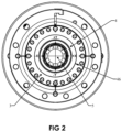
- Figure 1 shows the necessary gap 46 formed between the die set 4 & 5 and the clamp ring retainer 3. This gap is formed through the use of the "Floating Clamp Ring” design referenced above. The gap is small, typically between 0.127 mm (0.005") and 0.381 mm (0.015").
- This gap determines the amount of potential offset adjustment obtainable within the mechanism.
- the gap is evenly maintained through the use of an elastomer spring 8 and wear ring 9.
- elastomer spring 8 and wear ring 9 are seated within a circumferential channel in clamp ring 4.
- Wear ring 9 is made of a wear-resistant material intended to provide a longer life than the O-ring interface material used in prior art floating clamp ring solutions.
- the wear ring 9 may be constructed of a polyether ether ketone thermoplastic (PEEK) or a like low-wear material.
- Elastomer spring 8 is preferably constructed of a flexible compressible material and is constructed and arranged to compress radially.
- the elastomer spring 8 may be constructed of a fluoroelastomeric or like polymeric material. The latter material compositions are formulated to function in high-temperature conditions.
- the elastomer spring 8 has a multi-faceted cross-sectional configuration and which is shown seated within a circumferential channel of the clamp ring 4. By being able to compress radially, elastomer spring 8 provides the flexibility required to allow contact from a misaligned punch to move the clamp ring 4 in a direction that improves its axial alignment with the punch and corresponding can body.
- the generally rectangular or multi-faceted shape of elastomer spring 8 is shown in Figure 1 and is utilized with the cooperating wear ring 9, as opposed to an O-ring, as it increases the life of the material and prevents spiral failure of the material. Further, elastomer spring 8 provides greater surface area contact with wear ring 9, thereby providing a higher initial resistive force to reduce sagging of the clamp ring 4, which may result in misalignment.
- the die set 4 & 5 is designed to "float" around the center axis to match the position of the punch 45 as it engages the bottom former die set 4 & 5.
- the fit between the clamp ring 4 and the dome die 5 may be a taper. Such a taper fit allows the clamp ring to rock on the fixed dome die 5 to facilitate the alignment feature.
- the fit between the clamp ring 4 and the dome die 5 is a straight, tight fit.
- the dome die 5 in this design, is allowed to move with the clamp ring as it is manipulated. This is accomplished through the use of shoulder bolts 14.
- the holes through the dome die 5 are larger than the shoulder on the shoulder bolt, allowing off-center movement.
- This system is augmented through the use of spring washers 15 that keep a constant force on the dome die 5 along the punch travel axis. This force is also utilized to provide compression against the dome die environmental seal 33. This seal keeps coolant and lubricants from entering the bottom former cavity.
- Fig. 1 shows the die set sensing and adjustment assembly 2 as it is assembled to the floating clamp ring 4 and dome die 5.
- the sensor support tube 31 has a friction fit into the cavity of the dome die 5 with a seal 32 to prevent coolant and lubricants from entering and contaminating the junction.
- the friction fit allows any offset punch hit motion to be transferred into the thin walled portion of the sensor support tube 31, resulting in a bending moment.
- This bending moment creates strain on the walls of the tube 31.
- the strain is detected through an array of strain sensors 38 that are strategically placed around the diameter of the tube. The signals that are produced from these sensors 38 can be processed to indicate the direction and amplitude of the bending moment, thus indicating the position of the offset punch strike between the punch 45 and the bottom former die set 4 & 5.
- the processed signals from the strain sensors 38 can be utilized by the operator during initial equipment setup to align the bottom former to the punch.
- the data can also be utilized to monitor the alignment during the can making process to indicate process and equipment problems and maintenance requirements.
- the data can also be utilized for process trending.
- Information from the strain sensors 38 can be utilized as well to make offset hit centering adjustments of the die set, within the bottom former itself, either manually or automatically in a feedback loop.
- the sensor information can be used to make adjustments to the position of the bottom former die set 4 & 5 dynamically during the can making process.
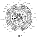
- the information can be used to drive (electrically, pneumatically, or hydraulically) one or more of the actuators to improve the alignment of the die set 4 & 5 relative to the punch. As shown in Fig.
- an array of actuators 44 can be either manually manipulated by use of a hand tool (such as a screwdriver or hex wrench), or automatically operated through the use of electric, pneumatic or hydraulic power.
- actuators 44 can be driven by the manual or powered turning of a threaded component that translates into linear motion.
- the strain sensors 38 can send electrical signals to an instrument that monitors the magnitude and direction of one or more off-center hits. This information is converted into signals that are sent to the actuators 44.
- the actuators 44 through their linkage mechanisms 48, provide a linear force, in either direction, corresponding to the direction and distance required to center the bottom former die set 4 & 5 relative to the punch 45.
- the offset hit information can be displayed for an operator to use during adjustment.
- the actuators 44 may be rotated or otherwise actuated, and movement of the linkage mechanisms 48 is transferred to the cross linkage shuttles 43. For example, if the top actuator in Fig. 7 is used, the vertical cross linkage shuttle 43, associated with torsion bars 35A and 35C, will move up or down.
- the cross linkage shuttles 43 actuate the torsion rod linkages 42 through a common pin. As the torsion rod linkages 42 rotate, a torsional force is applied to the torsion bars 35. In the example described above, if the cross linkage shuttle moves up, a clockwise torsion will be applied to bar 35A, while a counterclockwise torsion will be applied to torsion bar 35C. It should be noted that, although a single, common cross linkage shuttle 43 is shown, which can apply torque to two torsion bars at once, other configurations are possible. For example, an arrangement involving a single actuator providing torque to each torsion bar is possible.
- the torsion bars 35 (four in the illustrated embodiment) extend through the die set sensing and adjustment assembly 2 to a position near the die set 4 & 5.
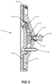
- the end of the torsion rod linkages 42 are formed in a manner to transfer the torsional force on them into a linear force that will act upon the sensor support tube 31 by way of a hole in the support tube through which the torsion rods pass near the bends in the rods.
- the linear force in turn moves die set 4 & 5 relative to the punch 45.
- the torsion bar anchor ring 36 provides an anchor point for the opposing linear force produced by the torsion bars 35.
- the torsion bar anchor ring 36 is held in place in cylinder housing 7 (see Fig. 3 ) by a retainer ring 34 and is secured so as to prevent motion radially through a friction fit in a matching cavity in the cylinder housing 7.
- Rotation of anchor ring 36 is prevented by a securing tab 49 which fits into a matching slot in housing 7.
- the anchor ring 36 is held in place in all directions within cylinder housing 7.
- there is a clearance between the outer diameter of support tube 31 and the inner diameter of anchor ring 36 which allows support tube 31 to move relative to the anchor ring 36.
- actuating force from the torsion bars 35 is applied to the sensor support tube 31 near, and providing motion radially, to the die set 4 & 5.
- x-y motion of support tube 31 is produced as follows: torque is applied at end 52 as described above. End 50 of torsion bar 35 is held stationary by anchor ring 36. Accordingly, a linear motion in or out of the page is produced near bend 51. Since torque rod bends such as that indicated by 51 exist in all the torsion bars near the holes in sensor support tube 31 through which the torsion bars pass, x-y forces can be applied to the support tube 31 that in turn move the dome die 5 and clamp ring 4. This is also illustrated in Fig. 8 .
- the torsion bars 35 can be utilized alone or in combination to provide the desired deflection distance and direction required to center the die set 4 & 5 to the punch, while at rest or during the can making process. Because the torsion bars 35 and the sensor support tube are mechanically allowed to deflect while in any operational position, the strain sensors 38 remain functional and continue to sense die set 4 & 5 position changes applied to them from the punch 45, such as from off-center hits.
- the torsion bar anchor ring 36 contains an anchor ring seal 37 that provides protection from coolant and lubricant intrusion into the mechanisms behind it. The anchor ring seal 37 also allows the sensor support tube 31 to deflect.
- the linkage cover 6 protects the mechanism from contaminants utilizing a cover seal 16 between the linkage cover 6 and the sensor support tube 31.
- the sensor support tube 31 is hollow to allow the passage of trapped coolant and lubricants, that are used in the can making process, from the coolant relief ports 29 in the dome die, to the coolant exhaust port 30. The coolant and lubricant is then expelled from the bottom former through an opening in the cylinder housing exhaust port 47 ( Fig. 3 ).
- the die set sensing and adjustment assembly 2 in combination with the floating dome die 5 and the floating clamp ring 4 create a mechanism that allows adjustment to the alignment between the can-forming punch 45, the floating clamp ring 4 and the floating dome die 5.
- the changes in this alignment can be enacted either manually or automatically.
- the die set sensing and adjustment assembly 2 has strain sensors 38 surrounding a portion of the sensor support tube 31 as shown in Fig. 1 . These strain sensors send electrical signals to a controller for display and manipulation. These signals are processed into directional force data and force amplitude data. This data is used to determine the direction and amplitude of the distance off center the can forming punch 45 is striking the bottom former die set. During the initial set up and alignment process, the user manually advances the can forming punch 45 into the bottom former die set 4&5. The controller will display the alignment information on the screen. Any indicated misalignment may be corrected by either manually adjusting the actuator linkage mechanism 48, or having the controller send a signal to one or both of the linkage actuators 44 to move the bottom former die set 4 & 5 into alignment.
- the controller will monitor the sensors during either adjustment type, manual or automatic, to determine when the strain sensors 38 begin to send a signal indicating further motion in the offset direction. This will indicate that the proper adjustment distance (x-y) has been achieved.
- the controller, or user may or may not decide to reverse the adjustment a small amount for over compensation.
- the value of the strain gauge signals is then stored in the controller for reference, and the value of these signals is used in further calculations as a base alignment location.
- a secondary base location can be used, during the can making process, to establish position base points for comparison during operation.
- the nature of the tubular shape of the sensor support tube 31 and the spring wire composition of the torsion bars 35 allow the mechanism to flex after any alignment movement action. This allows the strain sensors 38 to continue monitoring the alignment during and after an alignment adjustment.
- the can-forming punch 45 alignment to the bottom former die set 4 & 5 may be monitored and displayed on the controller. This information can be displayed in such a fashion to allow the user to determine the direction and magnitude of the misalignment offset. As misalignment occurs during can production, the operator may manually adjust the alignment utilizing one or more of the actuator linkage mechanism 48, or the controller can send signals to one or more of the actuators 44 to adjust the alignment dynamically. This realignment process allows the can-forming punch 45 to stay in alignment with the bottom former die set 4 & 5.
- the alignment between the can-forming punch 45 and the bottom former die set 4 & 5 tends to change. Automatically readjusting the alignment can result in a higher rate of can production.
- the result of the components being aligned results in the creation of more cans within the proper specification.
- the alignment data collected can be stored and trended for determining longer term problems. These long-term problems may include body maker component wear, bottom former setup and alignment issues, bottom former components wear and variances in can material.
- the data can be stored and reproduced for use during change-out of can geometries and shared between body-makers and can plants.
- the punch 45 strikes the clamp ring 4 first.
- the clamp ring 4 provides pressure to the outer ring on the bottom of the can as the punch 45 moves into the bottom former (left to right in Fig. 3 ). This pressure supports the material, and clamps it between punch 45 and clamp ring 4, allowing the following doming process to stretch and set the material into the desired can bottom shape.
- the force on the clamp ring 4 is produced by the clamp ring pressure piston 17, and transferred to the clamp ring 4 through piston push rods 41. The force is generated through the use of compressed air, introduced through the compressed air inlet 18.
- the force on the clamp ring 4 is critical to creating the proper shape of the can bottom. As shown in Fig.
- the signal generated by the cylinder pressure sensor 19 is utilized to verify the proper force is being applied to the clamp ring 4 during the can-making process. Adjustments to the pressure entering the compressed air inlet 18 can be made utilizing the signal from the cylinder pressure sensor 19. If a new type of can-bottom geometry or can making speed, or material changes are required, misformed cans are detected, or other factors require, the pressure can be manually or automatically adjusted and verified through the use of the cylinder pressure sensor 19 signal and either manually or automatically adjusting using electrical, pneumatic, or hydraulic actuators. Monitoring the cylinder pressure sensor 19 signal can also indicate issues in the can-making equipment that need to be addressed through maintenance.
- the air pressure supplied to the compressed air inlet 18 can be set either manually or automatically. Air pressure can be supplied from an air pressure regulator and adjusted, as needed, manually. The air pressure, in this configuration, can be manipulated manually if there are changes to the can size, can bottom configuration or bodymaker can production rate. This leaves open the possibility that unacceptable cans will be created after can style changeout or bodymaker speed changes during production.
- the pressure on the floating clamp ring 4 can be modified during a can geometry change over, or bodymaker speed change, without operator intervention.
- the pressure is manipulated by a controller.
- the pressure to be sent to the bottom former can be specified through a programmed look-up table or manipulated and stored by the operator through the controller's interface.
- the controller can constantly measure the air pressure and make adjustments in a feedback loop.
- the lookup table in the controller also has stored pressure data that corresponds to differing bodymaker speeds and differing can geometries and styles. These pressure settings can be used to adjust the pressure in accordance to the speed of the bodymaker during operation, as well as differing can geometries. This allows the floating clamp ring 4 force to be manipulated dynamically, during can production, to assure cans are made to specification. If the pressure falls out of a programmed tolerance window at any time, a fault can be logged in the controller.
- This fault signal can be used to inform the operator that maintenance must be performed on the bottom former or other equipment such as the bodymaker.
- the controller can also monitor the flow of the air being sent to the bottom former through the compressed air inlet 18. If the air flow is measured higher than a preprogrammed level, an error condition can be logged to warn the operator of potential clamp ring pressure piston 17 wear.
- the dome die 5 presses the dome shape into the bottom of the can utilizing the can-forming punch 45 to support the shape.
- the clamp ring then strikes the dome die 5.
- the can-forming punch 45, the clamp ring 4 and the dome die 5 apply pressure to the cylinder housing 7, pushing it back a short distance while being supported by the outer housing bearing sleeve 13. The distance traveled is commonly called over travel.
- This over travel compresses the dome setting spring 10 through the spring cover plate 28.
- the force applied by the dome setting spring 10 is opposed by the inner end plate 26 (see Fig. 5 ) within the setting force adjustment assembly 1.
- the setting force adjustment assembly 1 contains the outer end plate 25 which is firmly anchored to the outer housing 12 through an array of tension bolts 40 (see Figs. 6 & 7 ) .
- the force produced by the dome setting spring 10 ( Figs. 3 & 4 ) during the over travel sets the shape of the bottom of the can into the can material and is important to the can-making process.
- the initial force provided by the dome setting spring 10 is fixed through the use of differing materials and set distance pre-tensioning.
- the measured force is not typically known during operation.
- the setting force adjustment assembly 1, best shown in Fig. 5 allows the operator to set the initial force of the dome setting spring 10 by adjusting the spring force setting screw 20 either manually or automatically through an actuator.
- the actuator in the automatic configuration, may be electrical, pneumatic or hydraulic, and may be one of any number of common rotary actuators known to those of skill in the art.
- Adjustments can be made to the dome setting force manually by loosening the force setting screw jam nut 21, adjusting the dome setting force by turning the spring force setting screw 20 in or out, and retightening the force setting screw jam nut to lock in the setting, which as discussed herein can be measured by sensor 27.
- the dome setting force can also be manipulated automatically by utilizing an electrical, pneumatic of hydraulic actuator.
- the dome setting force is critical to creating cans to the customer's specifications. This force, typically, is a set value and cannot vary during installation or operation. The ability to change this force, either during initial setup, can geometry changeover, or during the can-making operation, enhances the ability to produce better cans at any production speed.
- the force produced to set the dome in the bottom former can be modified during a can geometry change over, or bodymaker speed change, without operator intervention.
- the dome setting force is adjusted by the controller.
- the force to be sent to the bottom former can be specified by a programmed lookup table or manipulated and stored by the operator through the controller's interface.
- the controller is constantly measuring the force utilizing the force sensor 27 located in the setting force and adjustment assembly 1 and making adjustments in a feedback loop.
- a lookup table in the controller also has stored force data that corresponds to differing bodymaker speeds. These force settings can be used to adjust the applied force in accordance to the speed of the bodymaker during operation.
- the signal being received at the controller from the force sensor 27 can be analyzed for its signal shape. The shape of this waveform can be analyzed by the controller to indicate faults in the can making process induced by material changes, equipment components wear or other factors.
- the force adjustment and adjustment assembly 1 utilizes an inner environmental seal 23 and an outer environmental seal 24. These seals prevent coolant and lubricant from entering the force and adjustment assembly 1, and also supply mechanical radial stability.
- the setting force and adjustment assembly allows the user to adjust the force being applied by the dome setting spring 10.
- the user can adjust the amount of setting force, applied to the can material during the can-making process, by turning the spring force setting screw 20.
- the spring force setting screw 20 applies force to a force sensor 27.
- the force sensor 27 sends a signal to a device that displays the force readings.
- the user may then increase or decrease the setting force applied during the bottom-forming process. This benefits the user by being able to quantify the setting force being applied during the can making process. This knowledge is valuable for creating consistently accurate cans across all of the body maker machines in the can plant.
- the information can be used, as well, to bring consistency to multiple can plants if the data is shared between them.
- the method for use, during initial bottom former setup is to first assure the spring force setting screw 20 is backed out to the point that there is no force being applied to the dome setting spring 10. This is accomplished by backing out the force setting screw 20 and watching the displayed data from sensor 27 until the force displayed is near or at zero.
- the bottom former is then installed, and aligned, into the body maker in usual fashion. Assuring that the can-forming punch 45 is retracted from the bottom former assembly, adjustments can be made to the setting force. These adjustments are made by turning the spring force setting screw 20 into the setting force and adjustment assembly 1 while watching the force increase on the display. When the force reading on the display reaches the desired level, the adjustment is complete. If the body maker is to be changed over to create a different can geometry, the initial setting force can be changed to meet the requirements of the new can.
- the setting force may be monitored, at a high frequency, and displayed on the display unit as a pulse, for every can made, during the over-travel portion of the bottom forming process.
- the initial force, maximum force, and the presence of the force are monitored by the display unit.
- the data collected during the can making process can be utilized to indicate anomalies in the bottom former process. Changes to the initial setting force, as indicated by the level measured while not in over travel, and anomalies such as dome setting spring 10 wear may be witnessed. This allows the user to either adjust the force to a higher level or change the dome setting spring 10. Changes to the maximum force, as indicated by the measurement at the peak of the force pulse, may indicate anomalies such as can material thickness changes, body maker driveline equipment changes or other changes occurring in the process. These long-term problems may include body maker component wear, bottom former setup and alignment issues, bottom former component wear and variances in can material.
- the data can be stored and reproduced for use during change-out of can geometries and shared between body-makers and can plants.
- the over-travel distance is measured through the use of an over travel distance sensor 11 (see Fig. 3 ) and may be of inductive or LVDT sensor type.
- the moveable sensor core is held in position with the sensor standoff 39.
- the sensor standoff 39 is used for the sensing surface.
- the position signal from travel distance sensor 11 may be used in combination with sensor 27 to further analyze or understand the over travel force applied by spring 10.
Landscapes
- Engineering & Computer Science (AREA)
- Mechanical Engineering (AREA)
- Shaping Metal By Deep-Drawing, Or The Like (AREA)
Claims (9)
- Durch Drehmoment betriebene Aktuatoranordnung zum Bilden von Domböden bei Dosenherstellung, wobei die Aktuatoranordnung aufweist:ein Ankerelement (36);wenigstens einen Torsionsstab (35) mit einem Drehmomentende und einem Betätigungsende, wobei ein auf den wenigstens einen Torsionsstab (35) in der Nähe des Drehmomentendes angelegtes Drehmoment eine Betätigungskraft mit einer radialen Translationskomponente an einem Abschnitt des Betätigungsendes des wenigstens einen Torsionsstabs erzeugt,dadurch gekennzeichnet, dass der wenigstens eine Torsionsstab (35) wenigstens 2 Biegungen zwischen dem Drehmomentende und dem Betätigungsende aufweist, wobei das Betätigungsende schwenkbar mit dem Ankerelement verbunden ist.
- Aktuatoranordnung nach Anspruch 1, wobei das Drehmomentende des wenigstens einen Torsionsstabs lagemäßig verankert ist, aber drehbar ist.
- Aktuatoranordnung nach Anspruch 2, ferner aufweisend ein Torsionsstabgestänge, das mit dem Drehmomentende des wenigstens einen Torsionsstabs verbunden ist, um das Drehmoment aufzubringen.
- Aktuatoranordnung nach Anspruch 3, wobei die wenigstens zwei Biegungen konfiguriert sind, um die translatorische Kraftkomponente aufgrund eines Abstands vom Rotationszentrum des Betätigungsendes und des Abschnitts des Betätigungsendes erzeugen.
- Aktuatoranordnung nach Anspruch 4, wobei der Abschnitt des Betätigungsendes schwenkbar mit einem Betätigungselement verbunden ist, und wobei die Translationskomponente das Betätigungselement bewegen wird.
- Aktuatoranordnung nach Anspruch 5, wobei der wenigstens eine Torsionsstab wenigstens einen ersten Torsionsstab und einen zweiten Torsionsstab aufweist, und wobei entweder die ersten und zweiten Torsionsstäbe konfiguriert sind, um im Wesentlichen gleiche Translationskräfte auf das Betätigungselement zu erzeugen, oder
wobei die ersten und zweiten Torsionsstäbe konfiguriert sind, um Translationskräfte auf das Betätigungselement zu erzeugen, wobei die Translationskräfte unterschiedliche Richtungen haben. - Aktuatoranordnung nach Anspruch 6, wobei die ersten und zweiten Torsionsstäbe konfiguriert sind, um im Wesentlichen gleiche Translationskräfte auf das Betätigungselement zu erzeugen, und wobei die im Wesentlichen gleichen Translationskräfte im Wesentlichen dieselbe Richtung sind.
- Aktuatoranordnung nach Anspruch 7, wobei einer durch den ersten Torsionsstab erzeugten Rotationskraftkomponente im Wesentlichen durch eine durch den zweiten Torsionsstab erzeugte Rotationskraftkomponente entgegengewirkt wird.
- Aktuatoranordnung nach Anspruch 8, wobei das Drehmoment auf den ersten und zweiten Torsionsstäben in entgegengesetzten Richtungen ausgeübt wird.
Priority Applications (1)
| Application Number | Priority Date | Filing Date | Title |
|---|---|---|---|
| EP21169220.7A EP3895825A1 (de) | 2017-01-20 | 2018-01-12 | Dome einstellkraft-einstellvorrichtung für einen dosenbodenformer |
Applications Claiming Priority (2)
| Application Number | Priority Date | Filing Date | Title |
|---|---|---|---|
| US15/411,822 US10441992B2 (en) | 2017-01-20 | 2017-01-20 | Can bottom former assembly |
| PCT/US2018/013522 WO2018136329A1 (en) | 2017-01-20 | 2018-01-12 | Can bottom former assembly |
Related Child Applications (2)
| Application Number | Title | Priority Date | Filing Date |
|---|---|---|---|
| EP21169220.7A Division-Into EP3895825A1 (de) | 2017-01-20 | 2018-01-12 | Dome einstellkraft-einstellvorrichtung für einen dosenbodenformer |
| EP21169220.7A Division EP3895825A1 (de) | 2017-01-20 | 2018-01-12 | Dome einstellkraft-einstellvorrichtung für einen dosenbodenformer |
Publications (3)
| Publication Number | Publication Date |
|---|---|
| EP3554733A1 EP3554733A1 (de) | 2019-10-23 |
| EP3554733A4 EP3554733A4 (de) | 2020-10-21 |
| EP3554733B1 true EP3554733B1 (de) | 2024-08-07 |
Family
ID=62905459
Family Applications (2)
| Application Number | Title | Priority Date | Filing Date |
|---|---|---|---|
| EP18742281.1A Active EP3554733B1 (de) | 2017-01-20 | 2018-01-12 | Dosenbodenformeranordnung |
| EP21169220.7A Withdrawn EP3895825A1 (de) | 2017-01-20 | 2018-01-12 | Dome einstellkraft-einstellvorrichtung für einen dosenbodenformer |
Family Applications After (1)
| Application Number | Title | Priority Date | Filing Date |
|---|---|---|---|
| EP21169220.7A Withdrawn EP3895825A1 (de) | 2017-01-20 | 2018-01-12 | Dome einstellkraft-einstellvorrichtung für einen dosenbodenformer |
Country Status (7)
| Country | Link |
|---|---|
| US (2) | US10441992B2 (de) |
| EP (2) | EP3554733B1 (de) |
| JP (1) | JP7015841B2 (de) |
| CN (2) | CN110494231B (de) |
| BR (1) | BR112019014973B1 (de) |
| ES (1) | ES2986653T3 (de) |
| WO (1) | WO2018136329A1 (de) |
Families Citing this family (6)
| Publication number | Priority date | Publication date | Assignee | Title |
|---|---|---|---|---|
| GB2561859B (en) * | 2017-04-25 | 2019-04-24 | Crown Packaging Technology Inc | Can base forming |
| US20220008981A1 (en) * | 2018-12-04 | 2022-01-13 | Novelis Inc. | Redraw and ironing system |
| JP7261984B2 (ja) * | 2019-09-18 | 2023-04-21 | パナソニックIpマネジメント株式会社 | 打ち抜き装置 |
| GB2594515B (en) * | 2020-05-01 | 2022-06-15 | Crown Packaging Technology Inc | Can bodymaker diagnostics |
| US20240001425A1 (en) * | 2020-12-15 | 2024-01-04 | Novelis Inc. | Improved ironing systems and methods |
| CN113290113B (zh) * | 2021-07-23 | 2021-09-21 | 南通丰利激光机械有限公司 | 一种模具加工系统 |
Family Cites Families (28)
| Publication number | Priority date | Publication date | Assignee | Title |
|---|---|---|---|---|
| US2075847A (en) * | 1930-05-16 | 1937-04-06 | American Can Co | Art of drawing |
| NL204163A (de) * | 1955-12-13 | |||
| US4733550A (en) * | 1986-01-29 | 1988-03-29 | Precision Products Of Tennessee, Inc. | Apparatus for forming a domed bottom in a can body |
| US4862723A (en) * | 1987-04-03 | 1989-09-05 | Davis Allen V C | Method and apparatus for producing precise length devices |
| CN2036119U (zh) * | 1988-03-24 | 1989-04-19 | 张家口市残疾人福利基金会 | 扭杆式牵引架助力装置 |
| US5125257A (en) * | 1991-06-04 | 1992-06-30 | Ball Corporation | Apparatus and method for doming bottoms of containers |
| US5380028A (en) * | 1992-04-27 | 1995-01-10 | John R. Ferris | Demountable trailer suspension system |
| US5378010A (en) * | 1992-09-23 | 1995-01-03 | Oshkosh Truck Corporation | Suspension system for trailer |
| GB9719549D0 (en) * | 1997-09-16 | 1997-11-19 | Metal Box Plc | Base forming |
| US6490904B1 (en) * | 2001-05-15 | 2002-12-10 | Mark L. Zauhar | Double action bottom former for high cyclic operation |
| MXPA03010734A (es) * | 2001-05-24 | 2005-03-07 | Metalforming Controls Corp | Prensa mecanica. |
| JP2003136144A (ja) * | 2001-11-07 | 2003-05-14 | Amada Co Ltd | 曲げ加工装置 |
| WO2003072482A1 (en) | 2002-02-28 | 2003-09-04 | Lift-U, Division Of Hogan Mfg., Inc. | Wheelchair lift for a stage |
| CN1593804A (zh) * | 2004-06-24 | 2005-03-16 | 沈阳工业学院 | 采用拉延筋控制方形坯料深拉延时压边力的方法及装置 |
| CN2713189Y (zh) * | 2004-07-07 | 2005-07-27 | 浙江工业大学 | 组合真空发生器 |
| ITMI20042517A1 (it) * | 2004-12-27 | 2005-03-27 | Frattini Costr Mecc | Dispositivo per il bloccaggio selettivo e progressivo di contenitori metallici |
| ES2371659T3 (es) * | 2005-02-02 | 2012-01-05 | Mark L. Zauhar | Conjunto de formación de fondos de lata. |
| US7124613B1 (en) | 2005-07-28 | 2006-10-24 | Stolle Machinery Company, Llc | Press and method of manufacturing a can end |
| US7526937B2 (en) * | 2006-02-02 | 2009-05-05 | Zauhar Mark L | Can bottom forming assembly |
| ITPR20070075A1 (it) * | 2007-10-09 | 2009-04-10 | Cft Packaging S P A | Aggraffatrice rotativa |
| CN201214117Y (zh) * | 2008-06-30 | 2009-04-01 | 南京航空航天大学 | 压力可调控板材渐进成形压头及其成形装置 |
| US9352379B2 (en) | 2009-04-07 | 2016-05-31 | Rexam Beverage Can Company | Tooling pod for double action can end press |
| RU2573850C2 (ru) | 2010-04-12 | 2016-01-27 | Краун Пэкэджинг Текнолоджи, Инк. | Изготовление банок |
| US8713980B2 (en) * | 2011-05-31 | 2014-05-06 | Stolle Machinery Company, Llc | Automatic domer positioning in a bodymaker |
| US8500185B1 (en) * | 2012-03-02 | 2013-08-06 | GM Global Technology Operations LLC | Decklid hinge counterbalance assembly having a straight end torque rod with infinite rotational adjustment |
| CN204486928U (zh) * | 2015-01-27 | 2015-07-22 | 宁波华元焊业有限公司 | 一种金属钢带的去毛刺设备 |
| CN205702211U (zh) * | 2016-02-23 | 2016-11-23 | 孙建锋 | 易撕盖生产线 |
| CN205669610U (zh) * | 2016-06-17 | 2016-11-02 | 中国铁道科学研究院 | 活塞式溢流阀 |
-
2017
- 2017-01-20 US US15/411,822 patent/US10441992B2/en active Active
-
2018
- 2018-01-12 ES ES18742281T patent/ES2986653T3/es active Active
- 2018-01-12 EP EP18742281.1A patent/EP3554733B1/de active Active
- 2018-01-12 CN CN201880019475.1A patent/CN110494231B/zh active Active
- 2018-01-12 BR BR112019014973-2A patent/BR112019014973B1/pt active IP Right Grant
- 2018-01-12 JP JP2019539823A patent/JP7015841B2/ja active Active
- 2018-01-12 EP EP21169220.7A patent/EP3895825A1/de not_active Withdrawn
- 2018-01-12 CN CN202011430412.0A patent/CN112692184A/zh not_active Withdrawn
- 2018-01-12 WO PCT/US2018/013522 patent/WO2018136329A1/en not_active Ceased
-
2019
- 2019-08-26 US US16/551,536 patent/US20190374995A1/en not_active Abandoned
Also Published As
| Publication number | Publication date |
|---|---|
| US20190374995A1 (en) | 2019-12-12 |
| BR112019014973A2 (pt) | 2020-04-14 |
| CN112692184A (zh) | 2021-04-23 |
| CN110494231A (zh) | 2019-11-22 |
| JP2020514068A (ja) | 2020-05-21 |
| US20180207706A1 (en) | 2018-07-26 |
| US10441992B2 (en) | 2019-10-15 |
| BR112019014973B1 (pt) | 2024-02-06 |
| CN110494231B (zh) | 2022-03-01 |
| WO2018136329A1 (en) | 2018-07-26 |
| EP3554733A1 (de) | 2019-10-23 |
| EP3554733A4 (de) | 2020-10-21 |
| EP3895825A1 (de) | 2021-10-20 |
| JP7015841B2 (ja) | 2022-02-03 |
| ES2986653T3 (es) | 2024-11-12 |
Similar Documents
| Publication | Publication Date | Title |
|---|---|---|
| EP3554733B1 (de) | Dosenbodenformeranordnung | |
| KR102255129B1 (ko) | 파스너 | |
| EP2454510B1 (de) | Verfahren und vorrichtung zum vorspannen einer ventildichtung | |
| US7346985B1 (en) | Bearing assembly spacer adjustment system and method for adjusting spacer | |
| US9216449B2 (en) | Controlled crimping method and system | |
| AU2018257980C1 (en) | Can base forming | |
| EP3819522B1 (de) | Lineares bewegungssystem | |
| CN103797275A (zh) | 电动缸和电动缸系统 | |
| CN110849736B (zh) | 一种压力测试工装及其使用方法 | |
| US6931982B1 (en) | Linear actuator | |
| US10987843B2 (en) | Pressure sensor for a metal or plastics processing tool | |
| JP2005526942A (ja) | サーボ制御の液圧ピストンで使用するためのサーボ制御の一体型の止め具 | |
| CN115605299B (zh) | 制罐机及操作制罐机以减轻工具磨损、损坏和/或错位的影响的方法 | |
| KR101724329B1 (ko) | 작동기의 백래시 및 강성 측정 장치 | |
| WO2001094796A1 (en) | Linear actuator | |
| US20240207918A1 (en) | Die assembly and method of manufacturing a container body | |
| KR20190062122A (ko) | 리니어 액추에이터 시스템 | |
| CN120659675A (zh) | 制造容器主体的模具组件和方法 | |
| CN121103999A (zh) | 一种冷镦机及其使用方法 | |
| CN120390678A (zh) | 力检测套环 | |
| AT522270A1 (de) | Einspritzeinheit und Formgebungsmaschine | |
| JPWO2013118656A1 (ja) | 動的変位計測装置および連携装置 |
Legal Events
| Date | Code | Title | Description |
|---|---|---|---|
| STAA | Information on the status of an ep patent application or granted ep patent |
Free format text: STATUS: THE INTERNATIONAL PUBLICATION HAS BEEN MADE |
|
| PUAI | Public reference made under article 153(3) epc to a published international application that has entered the european phase |
Free format text: ORIGINAL CODE: 0009012 |
|
| STAA | Information on the status of an ep patent application or granted ep patent |
Free format text: STATUS: REQUEST FOR EXAMINATION WAS MADE |
|
| 17P | Request for examination filed |
Effective date: 20190719 |
|
| AK | Designated contracting states |
Kind code of ref document: A1 Designated state(s): AL AT BE BG CH CY CZ DE DK EE ES FI FR GB GR HR HU IE IS IT LI LT LU LV MC MK MT NL NO PL PT RO RS SE SI SK SM TR |
|
| AX | Request for extension of the european patent |
Extension state: BA ME |
|
| RIN1 | Information on inventor provided before grant (corrected) |
Inventor name: SWEDBERG, RICK |
|
| DAV | Request for validation of the european patent (deleted) | ||
| DAX | Request for extension of the european patent (deleted) | ||
| RIC1 | Information provided on ipc code assigned before grant |
Ipc: B21D 22/28 20060101ALI20200625BHEP Ipc: B21D 51/26 20060101AFI20200625BHEP Ipc: B21D 22/30 20060101ALI20200625BHEP |
|
| A4 | Supplementary search report drawn up and despatched |
Effective date: 20200917 |
|
| RIC1 | Information provided on ipc code assigned before grant |
Ipc: B21D 51/26 20060101AFI20200911BHEP Ipc: B21D 22/30 20060101ALI20200911BHEP Ipc: B21D 22/28 20060101ALI20200911BHEP |
|
| STAA | Information on the status of an ep patent application or granted ep patent |
Free format text: STATUS: EXAMINATION IS IN PROGRESS |
|
| 17Q | First examination report despatched |
Effective date: 20221219 |
|
| GRAP | Despatch of communication of intention to grant a patent |
Free format text: ORIGINAL CODE: EPIDOSNIGR1 |
|
| STAA | Information on the status of an ep patent application or granted ep patent |
Free format text: STATUS: GRANT OF PATENT IS INTENDED |
|
| INTG | Intention to grant announced |
Effective date: 20240301 |
|
| GRAS | Grant fee paid |
Free format text: ORIGINAL CODE: EPIDOSNIGR3 |
|
| GRAA | (expected) grant |
Free format text: ORIGINAL CODE: 0009210 |
|
| STAA | Information on the status of an ep patent application or granted ep patent |
Free format text: STATUS: THE PATENT HAS BEEN GRANTED |
|
| AK | Designated contracting states |
Kind code of ref document: B1 Designated state(s): AL AT BE BG CH CY CZ DE DK EE ES FI FR GB GR HR HU IE IS IT LI LT LU LV MC MK MT NL NO PL PT RO RS SE SI SK SM TR |
|
| REG | Reference to a national code |
Ref country code: GB Ref legal event code: FG4D |
|
| REG | Reference to a national code |
Ref country code: CH Ref legal event code: EP |
|
| REG | Reference to a national code |
Ref country code: DE Ref legal event code: R096 Ref document number: 602018072760 Country of ref document: DE |
|
| REG | Reference to a national code |
Ref country code: IE Ref legal event code: FG4D |
|
| REG | Reference to a national code |
Ref country code: ES Ref legal event code: FG2A Ref document number: 2986653 Country of ref document: ES Kind code of ref document: T3 Effective date: 20241112 |
|
| REG | Reference to a national code |
Ref country code: LT Ref legal event code: MG9D |
|
| REG | Reference to a national code |
Ref country code: NL Ref legal event code: MP Effective date: 20240807 |
|
| PG25 | Lapsed in a contracting state [announced via postgrant information from national office to epo] |
Ref country code: NO Free format text: LAPSE BECAUSE OF FAILURE TO SUBMIT A TRANSLATION OF THE DESCRIPTION OR TO PAY THE FEE WITHIN THE PRESCRIBED TIME-LIMIT Effective date: 20241107 |
|
| REG | Reference to a national code |
Ref country code: AT Ref legal event code: MK05 Ref document number: 1710387 Country of ref document: AT Kind code of ref document: T Effective date: 20240807 |
|
| PG25 | Lapsed in a contracting state [announced via postgrant information from national office to epo] |
Ref country code: PT Free format text: LAPSE BECAUSE OF FAILURE TO SUBMIT A TRANSLATION OF THE DESCRIPTION OR TO PAY THE FEE WITHIN THE PRESCRIBED TIME-LIMIT Effective date: 20241209 Ref country code: FI Free format text: LAPSE BECAUSE OF FAILURE TO SUBMIT A TRANSLATION OF THE DESCRIPTION OR TO PAY THE FEE WITHIN THE PRESCRIBED TIME-LIMIT Effective date: 20240807 Ref country code: NL Free format text: LAPSE BECAUSE OF FAILURE TO SUBMIT A TRANSLATION OF THE DESCRIPTION OR TO PAY THE FEE WITHIN THE PRESCRIBED TIME-LIMIT Effective date: 20240807 Ref country code: GR Free format text: LAPSE BECAUSE OF FAILURE TO SUBMIT A TRANSLATION OF THE DESCRIPTION OR TO PAY THE FEE WITHIN THE PRESCRIBED TIME-LIMIT Effective date: 20241108 Ref country code: PL Free format text: LAPSE BECAUSE OF FAILURE TO SUBMIT A TRANSLATION OF THE DESCRIPTION OR TO PAY THE FEE WITHIN THE PRESCRIBED TIME-LIMIT Effective date: 20240807 |
|
| PGFP | Annual fee paid to national office [announced via postgrant information from national office to epo] |
Ref country code: GB Payment date: 20241206 Year of fee payment: 8 |
|
| PG25 | Lapsed in a contracting state [announced via postgrant information from national office to epo] |
Ref country code: BG Free format text: LAPSE BECAUSE OF FAILURE TO SUBMIT A TRANSLATION OF THE DESCRIPTION OR TO PAY THE FEE WITHIN THE PRESCRIBED TIME-LIMIT Effective date: 20240807 |
|
| PG25 | Lapsed in a contracting state [announced via postgrant information from national office to epo] |
Ref country code: LV Free format text: LAPSE BECAUSE OF FAILURE TO SUBMIT A TRANSLATION OF THE DESCRIPTION OR TO PAY THE FEE WITHIN THE PRESCRIBED TIME-LIMIT Effective date: 20240807 |
|
| PG25 | Lapsed in a contracting state [announced via postgrant information from national office to epo] |
Ref country code: AT Free format text: LAPSE BECAUSE OF FAILURE TO SUBMIT A TRANSLATION OF THE DESCRIPTION OR TO PAY THE FEE WITHIN THE PRESCRIBED TIME-LIMIT Effective date: 20240807 Ref country code: IS Free format text: LAPSE BECAUSE OF FAILURE TO SUBMIT A TRANSLATION OF THE DESCRIPTION OR TO PAY THE FEE WITHIN THE PRESCRIBED TIME-LIMIT Effective date: 20241207 |
|
| PG25 | Lapsed in a contracting state [announced via postgrant information from national office to epo] |
Ref country code: HR Free format text: LAPSE BECAUSE OF FAILURE TO SUBMIT A TRANSLATION OF THE DESCRIPTION OR TO PAY THE FEE WITHIN THE PRESCRIBED TIME-LIMIT Effective date: 20240807 |
|
| PG25 | Lapsed in a contracting state [announced via postgrant information from national office to epo] |
Ref country code: RS Free format text: LAPSE BECAUSE OF FAILURE TO SUBMIT A TRANSLATION OF THE DESCRIPTION OR TO PAY THE FEE WITHIN THE PRESCRIBED TIME-LIMIT Effective date: 20241107 |
|
| PG25 | Lapsed in a contracting state [announced via postgrant information from national office to epo] |
Ref country code: RS Free format text: LAPSE BECAUSE OF FAILURE TO SUBMIT A TRANSLATION OF THE DESCRIPTION OR TO PAY THE FEE WITHIN THE PRESCRIBED TIME-LIMIT Effective date: 20241107 Ref country code: PT Free format text: LAPSE BECAUSE OF FAILURE TO SUBMIT A TRANSLATION OF THE DESCRIPTION OR TO PAY THE FEE WITHIN THE PRESCRIBED TIME-LIMIT Effective date: 20241209 Ref country code: PL Free format text: LAPSE BECAUSE OF FAILURE TO SUBMIT A TRANSLATION OF THE DESCRIPTION OR TO PAY THE FEE WITHIN THE PRESCRIBED TIME-LIMIT Effective date: 20240807 Ref country code: NO Free format text: LAPSE BECAUSE OF FAILURE TO SUBMIT A TRANSLATION OF THE DESCRIPTION OR TO PAY THE FEE WITHIN THE PRESCRIBED TIME-LIMIT Effective date: 20241107 Ref country code: NL Free format text: LAPSE BECAUSE OF FAILURE TO SUBMIT A TRANSLATION OF THE DESCRIPTION OR TO PAY THE FEE WITHIN THE PRESCRIBED TIME-LIMIT Effective date: 20240807 Ref country code: LV Free format text: LAPSE BECAUSE OF FAILURE TO SUBMIT A TRANSLATION OF THE DESCRIPTION OR TO PAY THE FEE WITHIN THE PRESCRIBED TIME-LIMIT Effective date: 20240807 Ref country code: IS Free format text: LAPSE BECAUSE OF FAILURE TO SUBMIT A TRANSLATION OF THE DESCRIPTION OR TO PAY THE FEE WITHIN THE PRESCRIBED TIME-LIMIT Effective date: 20241207 Ref country code: HR Free format text: LAPSE BECAUSE OF FAILURE TO SUBMIT A TRANSLATION OF THE DESCRIPTION OR TO PAY THE FEE WITHIN THE PRESCRIBED TIME-LIMIT Effective date: 20240807 Ref country code: GR Free format text: LAPSE BECAUSE OF FAILURE TO SUBMIT A TRANSLATION OF THE DESCRIPTION OR TO PAY THE FEE WITHIN THE PRESCRIBED TIME-LIMIT Effective date: 20241108 Ref country code: FI Free format text: LAPSE BECAUSE OF FAILURE TO SUBMIT A TRANSLATION OF THE DESCRIPTION OR TO PAY THE FEE WITHIN THE PRESCRIBED TIME-LIMIT Effective date: 20240807 Ref country code: BG Free format text: LAPSE BECAUSE OF FAILURE TO SUBMIT A TRANSLATION OF THE DESCRIPTION OR TO PAY THE FEE WITHIN THE PRESCRIBED TIME-LIMIT Effective date: 20240807 Ref country code: AT Free format text: LAPSE BECAUSE OF FAILURE TO SUBMIT A TRANSLATION OF THE DESCRIPTION OR TO PAY THE FEE WITHIN THE PRESCRIBED TIME-LIMIT Effective date: 20240807 |
|
| PGFP | Annual fee paid to national office [announced via postgrant information from national office to epo] |
Ref country code: DE Payment date: 20241209 Year of fee payment: 8 |
|
| PG25 | Lapsed in a contracting state [announced via postgrant information from national office to epo] |
Ref country code: DK Free format text: LAPSE BECAUSE OF FAILURE TO SUBMIT A TRANSLATION OF THE DESCRIPTION OR TO PAY THE FEE WITHIN THE PRESCRIBED TIME-LIMIT Effective date: 20240807 Ref country code: RO Free format text: LAPSE BECAUSE OF FAILURE TO SUBMIT A TRANSLATION OF THE DESCRIPTION OR TO PAY THE FEE WITHIN THE PRESCRIBED TIME-LIMIT Effective date: 20240807 Ref country code: SM Free format text: LAPSE BECAUSE OF FAILURE TO SUBMIT A TRANSLATION OF THE DESCRIPTION OR TO PAY THE FEE WITHIN THE PRESCRIBED TIME-LIMIT Effective date: 20240807 |
|
| PGFP | Annual fee paid to national office [announced via postgrant information from national office to epo] |
Ref country code: ES Payment date: 20250203 Year of fee payment: 8 |
|
| PG25 | Lapsed in a contracting state [announced via postgrant information from national office to epo] |
Ref country code: EE Free format text: LAPSE BECAUSE OF FAILURE TO SUBMIT A TRANSLATION OF THE DESCRIPTION OR TO PAY THE FEE WITHIN THE PRESCRIBED TIME-LIMIT Effective date: 20240807 |
|
| PG25 | Lapsed in a contracting state [announced via postgrant information from national office to epo] |
Ref country code: CZ Free format text: LAPSE BECAUSE OF FAILURE TO SUBMIT A TRANSLATION OF THE DESCRIPTION OR TO PAY THE FEE WITHIN THE PRESCRIBED TIME-LIMIT Effective date: 20240807 |
|
| PGFP | Annual fee paid to national office [announced via postgrant information from national office to epo] |
Ref country code: FR Payment date: 20250129 Year of fee payment: 8 |
|
| PG25 | Lapsed in a contracting state [announced via postgrant information from national office to epo] |
Ref country code: SK Free format text: LAPSE BECAUSE OF FAILURE TO SUBMIT A TRANSLATION OF THE DESCRIPTION OR TO PAY THE FEE WITHIN THE PRESCRIBED TIME-LIMIT Effective date: 20240807 |
|
| REG | Reference to a national code |
Ref country code: DE Ref legal event code: R097 Ref document number: 602018072760 Country of ref document: DE |
|
| PLBE | No opposition filed within time limit |
Free format text: ORIGINAL CODE: 0009261 |
|
| STAA | Information on the status of an ep patent application or granted ep patent |
Free format text: STATUS: NO OPPOSITION FILED WITHIN TIME LIMIT |
|
| 26N | No opposition filed |
Effective date: 20250508 |
|
| REG | Reference to a national code |
Ref country code: CH Ref legal event code: PL |
|
| PG25 | Lapsed in a contracting state [announced via postgrant information from national office to epo] |
Ref country code: SE Free format text: LAPSE BECAUSE OF FAILURE TO SUBMIT A TRANSLATION OF THE DESCRIPTION OR TO PAY THE FEE WITHIN THE PRESCRIBED TIME-LIMIT Effective date: 20240807 |
|
| PG25 | Lapsed in a contracting state [announced via postgrant information from national office to epo] |
Ref country code: LU Free format text: LAPSE BECAUSE OF NON-PAYMENT OF DUE FEES Effective date: 20250112 Ref country code: MC Free format text: LAPSE BECAUSE OF FAILURE TO SUBMIT A TRANSLATION OF THE DESCRIPTION OR TO PAY THE FEE WITHIN THE PRESCRIBED TIME-LIMIT Effective date: 20240807 |
|
| PG25 | Lapsed in a contracting state [announced via postgrant information from national office to epo] |
Ref country code: BE Free format text: LAPSE BECAUSE OF NON-PAYMENT OF DUE FEES Effective date: 20250131 |
|
| PG25 | Lapsed in a contracting state [announced via postgrant information from national office to epo] |
Ref country code: CH Free format text: LAPSE BECAUSE OF NON-PAYMENT OF DUE FEES Effective date: 20250131 |
|
| REG | Reference to a national code |
Ref country code: BE Ref legal event code: MM Effective date: 20250131 |