EP3554597B1 - Vapor production device, system, method for producing inhalable vapor, and kit - Google Patents
Vapor production device, system, method for producing inhalable vapor, and kit Download PDFInfo
- Publication number
- EP3554597B1 EP3554597B1 EP17826060.0A EP17826060A EP3554597B1 EP 3554597 B1 EP3554597 B1 EP 3554597B1 EP 17826060 A EP17826060 A EP 17826060A EP 3554597 B1 EP3554597 B1 EP 3554597B1
- Authority
- EP
- European Patent Office
- Prior art keywords
- vapor
- production device
- storage container
- vapor production
- compressor
- Prior art date
- Legal status (The legal status is an assumption and is not a legal conclusion. Google has not performed a legal analysis and makes no representation as to the accuracy of the status listed.)
- Active
Links
Images

Classifications
-
- A—HUMAN NECESSITIES
- A24—TOBACCO; CIGARS; CIGARETTES; SIMULATED SMOKING DEVICES; SMOKERS' REQUISITES
- A24F—SMOKERS' REQUISITES; MATCH BOXES; SIMULATED SMOKING DEVICES
- A24F40/00—Electrically operated smoking devices; Component parts thereof; Manufacture thereof; Maintenance or testing thereof; Charging means specially adapted therefor
- A24F40/40—Constructional details, e.g. connection of cartridges and battery parts
- A24F40/48—Fluid transfer means, e.g. pumps
- A24F40/485—Valves; Apertures
-
- A—HUMAN NECESSITIES
- A24—TOBACCO; CIGARS; CIGARETTES; SIMULATED SMOKING DEVICES; SMOKERS' REQUISITES
- A24F—SMOKERS' REQUISITES; MATCH BOXES; SIMULATED SMOKING DEVICES
- A24F40/00—Electrically operated smoking devices; Component parts thereof; Manufacture thereof; Maintenance or testing thereof; Charging means specially adapted therefor
- A24F40/40—Constructional details, e.g. connection of cartridges and battery parts
- A24F40/48—Fluid transfer means, e.g. pumps
-
- A—HUMAN NECESSITIES
- A24—TOBACCO; CIGARS; CIGARETTES; SIMULATED SMOKING DEVICES; SMOKERS' REQUISITES
- A24B—MANUFACTURE OR PREPARATION OF TOBACCO FOR SMOKING OR CHEWING; TOBACCO; SNUFF
- A24B15/00—Chemical features or treatment of tobacco; Tobacco substitutes, e.g. in liquid form
- A24B15/10—Chemical features of tobacco products or tobacco substitutes
- A24B15/16—Chemical features of tobacco products or tobacco substitutes of tobacco substitutes
- A24B15/167—Chemical features of tobacco products or tobacco substitutes of tobacco substitutes in liquid or vaporisable form, e.g. liquid compositions for electronic cigarettes
-
- A—HUMAN NECESSITIES
- A24—TOBACCO; CIGARS; CIGARETTES; SIMULATED SMOKING DEVICES; SMOKERS' REQUISITES
- A24F—SMOKERS' REQUISITES; MATCH BOXES; SIMULATED SMOKING DEVICES
- A24F40/00—Electrically operated smoking devices; Component parts thereof; Manufacture thereof; Maintenance or testing thereof; Charging means specially adapted therefor
- A24F40/10—Devices using liquid inhalable precursors
-
- A—HUMAN NECESSITIES
- A24—TOBACCO; CIGARS; CIGARETTES; SIMULATED SMOKING DEVICES; SMOKERS' REQUISITES
- A24F—SMOKERS' REQUISITES; MATCH BOXES; SIMULATED SMOKING DEVICES
- A24F40/00—Electrically operated smoking devices; Component parts thereof; Manufacture thereof; Maintenance or testing thereof; Charging means specially adapted therefor
- A24F40/40—Constructional details, e.g. connection of cartridges and battery parts
- A24F40/42—Cartridges or containers for inhalable precursors
-
- A—HUMAN NECESSITIES
- A24—TOBACCO; CIGARS; CIGARETTES; SIMULATED SMOKING DEVICES; SMOKERS' REQUISITES
- A24F—SMOKERS' REQUISITES; MATCH BOXES; SIMULATED SMOKING DEVICES
- A24F40/00—Electrically operated smoking devices; Component parts thereof; Manufacture thereof; Maintenance or testing thereof; Charging means specially adapted therefor
- A24F40/40—Constructional details, e.g. connection of cartridges and battery parts
- A24F40/46—Shape or structure of electric heating means
-
- A—HUMAN NECESSITIES
- A61—MEDICAL OR VETERINARY SCIENCE; HYGIENE
- A61M—DEVICES FOR INTRODUCING MEDIA INTO, OR ONTO, THE BODY; DEVICES FOR TRANSDUCING BODY MEDIA OR FOR TAKING MEDIA FROM THE BODY; DEVICES FOR PRODUCING OR ENDING SLEEP OR STUPOR
- A61M11/00—Sprayers or atomisers specially adapted for therapeutic purposes
- A61M11/04—Sprayers or atomisers specially adapted for therapeutic purposes operated by the vapour pressure of the liquid to be sprayed or atomised
- A61M11/041—Sprayers or atomisers specially adapted for therapeutic purposes operated by the vapour pressure of the liquid to be sprayed or atomised using heaters
-
- A—HUMAN NECESSITIES
- A61—MEDICAL OR VETERINARY SCIENCE; HYGIENE
- A61M—DEVICES FOR INTRODUCING MEDIA INTO, OR ONTO, THE BODY; DEVICES FOR TRANSDUCING BODY MEDIA OR FOR TAKING MEDIA FROM THE BODY; DEVICES FOR PRODUCING OR ENDING SLEEP OR STUPOR
- A61M15/00—Inhalators
- A61M15/06—Inhaling appliances shaped like cigars, cigarettes or pipes
-
- F—MECHANICAL ENGINEERING; LIGHTING; HEATING; WEAPONS; BLASTING
- F17—STORING OR DISTRIBUTING GASES OR LIQUIDS
- F17C—VESSELS FOR CONTAINING OR STORING COMPRESSED, LIQUEFIED OR SOLIDIFIED GASES; FIXED-CAPACITY GAS-HOLDERS; FILLING VESSELS WITH, OR DISCHARGING FROM VESSELS, COMPRESSED, LIQUEFIED, OR SOLIDIFIED GASES
- F17C7/00—Methods or apparatus for discharging liquefied, solidified, or compressed gases from pressure vessels, not covered by another subclass
- F17C7/02—Discharging liquefied gases
- F17C7/04—Discharging liquefied gases with change of state, e.g. vaporisation
-
- H—ELECTRICITY
- H05—ELECTRIC TECHNIQUES NOT OTHERWISE PROVIDED FOR
- H05B—ELECTRIC HEATING; ELECTRIC LIGHT SOURCES NOT OTHERWISE PROVIDED FOR; CIRCUIT ARRANGEMENTS FOR ELECTRIC LIGHT SOURCES, IN GENERAL
- H05B1/00—Details of electric heating devices
- H05B1/02—Automatic switching arrangements specially adapted to apparatus ; Control of heating devices
- H05B1/0227—Applications
- H05B1/023—Industrial applications
- H05B1/0244—Heating of fluids
-
- A—HUMAN NECESSITIES
- A24—TOBACCO; CIGARS; CIGARETTES; SIMULATED SMOKING DEVICES; SMOKERS' REQUISITES
- A24F—SMOKERS' REQUISITES; MATCH BOXES; SIMULATED SMOKING DEVICES
- A24F40/00—Electrically operated smoking devices; Component parts thereof; Manufacture thereof; Maintenance or testing thereof; Charging means specially adapted therefor
-
- A—HUMAN NECESSITIES
- A61—MEDICAL OR VETERINARY SCIENCE; HYGIENE
- A61M—DEVICES FOR INTRODUCING MEDIA INTO, OR ONTO, THE BODY; DEVICES FOR TRANSDUCING BODY MEDIA OR FOR TAKING MEDIA FROM THE BODY; DEVICES FOR PRODUCING OR ENDING SLEEP OR STUPOR
- A61M15/00—Inhalators
- A61M15/009—Inhalators using medicine packages with incorporated spraying means, e.g. aerosol cans
-
- A—HUMAN NECESSITIES
- A61—MEDICAL OR VETERINARY SCIENCE; HYGIENE
- A61M—DEVICES FOR INTRODUCING MEDIA INTO, OR ONTO, THE BODY; DEVICES FOR TRANSDUCING BODY MEDIA OR FOR TAKING MEDIA FROM THE BODY; DEVICES FOR PRODUCING OR ENDING SLEEP OR STUPOR
- A61M16/00—Devices for influencing the respiratory system of patients by gas treatment, e.g. ventilators; Tracheal tubes
- A61M16/0057—Pumps therefor
- A61M16/0063—Compressors
-
- A—HUMAN NECESSITIES
- A61—MEDICAL OR VETERINARY SCIENCE; HYGIENE
- A61M—DEVICES FOR INTRODUCING MEDIA INTO, OR ONTO, THE BODY; DEVICES FOR TRANSDUCING BODY MEDIA OR FOR TAKING MEDIA FROM THE BODY; DEVICES FOR PRODUCING OR ENDING SLEEP OR STUPOR
- A61M2205/00—General characteristics of the apparatus
- A61M2205/33—Controlling, regulating or measuring
- A61M2205/3368—Temperature
-
- A—HUMAN NECESSITIES
- A61—MEDICAL OR VETERINARY SCIENCE; HYGIENE
- A61M—DEVICES FOR INTRODUCING MEDIA INTO, OR ONTO, THE BODY; DEVICES FOR TRANSDUCING BODY MEDIA OR FOR TAKING MEDIA FROM THE BODY; DEVICES FOR PRODUCING OR ENDING SLEEP OR STUPOR
- A61M2205/00—General characteristics of the apparatus
- A61M2205/36—General characteristics of the apparatus related to heating or cooling
- A61M2205/3653—General characteristics of the apparatus related to heating or cooling by Joule effect, i.e. electric resistance
-
- A—HUMAN NECESSITIES
- A61—MEDICAL OR VETERINARY SCIENCE; HYGIENE
- A61M—DEVICES FOR INTRODUCING MEDIA INTO, OR ONTO, THE BODY; DEVICES FOR TRANSDUCING BODY MEDIA OR FOR TAKING MEDIA FROM THE BODY; DEVICES FOR PRODUCING OR ENDING SLEEP OR STUPOR
- A61M2205/00—General characteristics of the apparatus
- A61M2205/50—General characteristics of the apparatus with microprocessors or computers
-
- A—HUMAN NECESSITIES
- A61—MEDICAL OR VETERINARY SCIENCE; HYGIENE
- A61M—DEVICES FOR INTRODUCING MEDIA INTO, OR ONTO, THE BODY; DEVICES FOR TRANSDUCING BODY MEDIA OR FOR TAKING MEDIA FROM THE BODY; DEVICES FOR PRODUCING OR ENDING SLEEP OR STUPOR
- A61M2209/00—Ancillary equipment
- A61M2209/04—Tools for specific apparatus
- A61M2209/045—Tools for specific apparatus for filling, e.g. for filling reservoirs
-
- F—MECHANICAL ENGINEERING; LIGHTING; HEATING; WEAPONS; BLASTING
- F17—STORING OR DISTRIBUTING GASES OR LIQUIDS
- F17C—VESSELS FOR CONTAINING OR STORING COMPRESSED, LIQUEFIED OR SOLIDIFIED GASES; FIXED-CAPACITY GAS-HOLDERS; FILLING VESSELS WITH, OR DISCHARGING FROM VESSELS, COMPRESSED, LIQUEFIED, OR SOLIDIFIED GASES
- F17C2227/00—Transfer of fluids, i.e. method or means for transferring the fluid; Heat exchange with the fluid
- F17C2227/03—Heat exchange with the fluid
- F17C2227/0367—Localisation of heat exchange
- F17C2227/0388—Localisation of heat exchange separate
- F17C2227/0393—Localisation of heat exchange separate using a vaporiser
-
- H—ELECTRICITY
- H05—ELECTRIC TECHNIQUES NOT OTHERWISE PROVIDED FOR
- H05B—ELECTRIC HEATING; ELECTRIC LIGHT SOURCES NOT OTHERWISE PROVIDED FOR; CIRCUIT ARRANGEMENTS FOR ELECTRIC LIGHT SOURCES, IN GENERAL
- H05B2203/00—Aspects relating to Ohmic resistive heating covered by group H05B3/00
- H05B2203/021—Heaters specially adapted for heating liquids
Definitions
- This disclosure relates generally to vaporizers, and more particularly to a vapor production system capable of storing vapor.
- Vaporizers have recently emerged as a new product for providing nicotine and other products through a smokeless inhalation process.
- vaporizers including the electronic cigarette.
- Most implementations consist of a power supply (typically a battery) and an atomizing device.
- a power supply typically a battery
- an atomizing device In reusable electronic cigarettes the two items are separated into a battery and a cartomizer, to allow the disposal and replacement of the nicotine containing fluid cartomizer while preserving the more costly battery and associated circuitry (microcontroller, switch, indicating LED, etc.)
- disposable electronic cigarettes the two items are combined to integrate the functions into one unit that is disposed of after either the battery energy or the nicotine containing E-liquid is exhausted.
- Vaporizers are generally designed to provide a supply of vapor on demand to a single user. In instances where multiple users are present, each user typically has their own vaporizer.
- the E-liquid that is used to produce vapor in electronic cigarettes is generally a solution of one or more of propylene glycol (PG) and/or vegetable glycerin (VG) and/or polyethylene glycol 400 (PEG400) mixed with concentrated flavors, and optionally, a variable percentage of a liquid nicotine concentrate.
- This liquid may be termed an "E-liquid” and is often sold in a bottle or in disposable cartridges or cartomizers.
- Many different flavors of such E-liquids are sold, including flavors that resemble the taste of regular tobacco, menthol, vanilla, coffee, cola and various fruits.
- Various nicotine concentrations are also available, and nicotine-free E-Liquids are also common.
- US 2016331034 A1 describes an electronic vapor device comprising: a vapor outlet; a first container for storing a first vaporizable material, wherein the first container is permanently integrated into the electronic vapor device; a second container for storing a second vaporizable material, wherein the second container is removable from the electronic vapor device; a docking bay configured to receive the second container, wherein the second container is removed from or inserted into the docking bay through a door; and a vaporizer component configured for vaporizing the first vaporizable material or the second vaporizable material to generate a vapor and for providing the vapor to the vapor outlet.
- US 2016331034 discloses, in a separate embodiment: a vaporizer comprising a depressurization chamber, a vapor chamber, a first vapor conduit, a second vapor conduit, and a processor; and a container configured to hold a pre-vaporized liquid, under pressure, wherein the pre-vaporized liquid was generated, pressurized, and stored for later use; for example, a vaporizable element may be vaporized externally to the electronic vapor device; the vapor generated can be captured, compressed, and stored in the container; or, during the manufacture of the vaporizer, the vaporizable element may be created in the vaporizer device itself and compressed, and stored in the container; for example, an aerosol may be formed in carbon dioxide, compressed using equipment for compressing carbon dioxide, and stored in a cartridge suitable for carbon dioxide; in an alternative, pure carbon dioxide or other carrier gas may be pressurized and introduced into a cartridge that already contains a quantity of the material to be aerosolized, for example a powdered or liquid material.
- US 2014212517 discloses a device for capturing a component of a vapor, comprising a vaporizer and a vapor trap, the vapor trap in communication with a vaporizer outlet.
- the vaporizer has an air pump, an air inlet upstream of the air pump, an air heater in communication with the air pump, a vaporization chamber in communication with the air pump and downstream of the air heater, and a vaporizer outlet downstream of the vaporization chamber.
- a quantity of a vaporizing material is positioned within the vaporization chamber.
- the vapor trap forms an interior reservoir and has a vapor inlet and a vapor outlet positioned on opposite sides.
- a first container is positioned just downstream of the vapor inlet, which is configured to allow a vapor inlet flow and simultaneously prevent escape of the vapor trapping media through the vapor inlet.
- a second container is positioned just upstream of the vapor outlet, configured to allow a vapor outlet flow and simultaneously to prevent escape of the vapor trapping media through the vapor outlet.
- US 6513524 discloses a table-top apparatus with a seated receptacle and a valve as well as a vapor balloon.
- a hot air generator comprised of a motor, propeller, heat chamber and air flow tube which draws in the air from below through an air inlet provided in the base, heats and, following the laws of physics, in accordance with which heated air climbs upwards, conveys this upwards (“volcano"-smoke stack).
- a temperature regulator as well as an on/off switch.
- the receptacle includes a receptacle chamber in which either a plant material to be vaporized is loosely filled in or a crucible with a fluid to be vaporized is introduced.
- the receptacle further comprises a smoke detector to monitor the vapor upon the development of undesired smoke.
- the smoke detector provides a signal to a controller to regulate the temperature of the hot air source.
- the valve is comprised of a light metal block in which a valve cylinder and a valve spring wound on the outside of the valve cylinder are provided.
- the valve cylinder is rigidly connected with the valve cover via spacers. The openings between the spacers make it possible for the vapor to can travel into and out of the balloon while the valve is opened.
- the funnel shape itself insures for a perfect sealing when the valve is closed, and also holds the balloon securely in its place.
- the vapor balloon is comprised of a balloon jacket and a balloon retainer. Hot air is blown through the plant material and thereby the aroma- and active substances are transitioned into vapor, which is directed into the balloon via the valve and is collected there. The vapor can then be inhaled out of this balloon by means of a mouthpiece connected to the valve.
- a vapor production device according to claim 1
- a system according to claim 5 a method according to claim 8 and a kit according to claim 10.
- Preferred embodiments of the invention are defined in the dependent claims 2-4, 6, 7, 9 and 11-13.
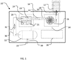
- FIG. 1 illustrates a schematic view of a vapor production system 10.
- Vapor production system 10 is generally a system for producing compressed vapor suitable for filling a container 12 for later consumption by an end user. Once filled by vapor production system 10, container 12 may be used to consume vapor absent the vapor production system 10. Thus, vapor may be available in a setting that may not allow a traditional vaporizer, or in situations in which a high vapor production rate is required.
- Vapor production system 10 is contained within a portable case 14.
- Portable case 14 is powered by way of batteries, an external power source, or a combination of batteries and an external power system.
- Portable case 14 has an outer surface with an inlet 16 for receiving air, an outlet 18 for produced vapor, and vaporizable material chamber 20 for receiving vaporizable material to be vaporized.
- the vaporizable material chamber 20 may receive cartridges containing particular types of vaporizable materials, or it may receive the raw vaporizable materials to be vaporized.
- the components Contained within portable case 14 are components for producing vapor. Also contained within some embodiments of the vapor production system or its portable case are components for compressing vapor. In yet other embodiments, components for both producing vapor and for its compression are contained within the vapor production system or its portable case. As shown in FIG. 1 , the components includes an air pump 22, a heating center 24, a vapor compressor 26, and a control panel 28. Additionally, each component is in fluid communication with adjacent components though air channels 30 with fluid flow between components controlled by valves 32. Control panel 28 is wired to each component and one or more valves 32 through common techniques as known by one of ordinary skill in the art. Dashed line 34 indicates the connection between control panel 28 and the components.
- Air pump 22 receives ambient air through inlet 16.
- Inlet 16 may be connected directly to air pump 22, or as shown in the embodiment of FIG. 1 , inlet 16 may connect to air pump 22 by way of air passage 32.
- Inlet 16 may have a filter suitable to prevent foreign material from entering air pump 22.
- Air pump 22 may be any type of air pump as known in the art. Air pump 22 directs a volume of air thorough an air channel 30 to heating center 24. A first valve 32 is present in air channel 30 and prevents air from flowing into heating center 24 from air pump 22 when not in use. Valve 32 may be adjustable, to regulate the flow of air, or act as a simple on/off valve.
- Air channel 30 is in fluid communication with heating center 24.
- Heating center 24 has a chamber 20 for receiving vaporizable material 21 and a heater for vaporizing vaporizable material 21. Heating center 24 heats vaporizable material 21 to produce vapor 23 as is known in the art. Air supplied through air channel 30 mixes with vapor 23 to produce an inhalable vapor.
- a second air channel 30 directs inhalable vapor from heating center 30 into vapor compressor 26.
- Vapor compressor 26 receives inhalable vapor, compresses it, and directs the compressed vapor to outlet 18.
- Vapor container 12 is secured to outlet 18 to receive the compressed vapor.
- Vapor container 12 may be attached, connected or secured to portable case 14 or vapor production system 10 during filling using common techniques such as a threaded connection or a twist lock connection.
- the compressed vapor contained within the vapor container 12 may then be used independently of the vapor production device 10. Additionally, the compressed vapor may be delivered at a much higher flow rate than what is available using a standard vaporizer. Because the vapor is compressed, vapor container 12 may hold a larger quantity than would otherwise be possible.
- Control panel 28 is configured to control the components of the vapor control system. Control panel 28 regulates the power delivered to the heating center 24 to convert the vaporizable material to vapor at a temperature suitable for its vaporization. The suitable temperature may be entered manually by an operator, or control panel 28 may have stored data indicating an optimal temperature or heating profile. The quantity of air delivered to heating center 24 may be or is controlled by the control panel 28 and may be adjusted in combination with the power delivered to the heating center for optimal vapor production. Compressor 26 is further controlled by control panel 28 to deliver an optimal pressure for storage of the inhalable vapor. Depending on the type of vapor container and the vaporizable material being vaporized, compressor 26 regulates the level of compression to which the inhalable vapor is compressed.
- vapor container 12 Once vapor container 12 is filled with vapor mixture to a desired pressure, vapor container 12 may be detached or otherwise disconnected from portable case 14 or vapor production system 10.
- Vapor container 12 may be a small can shaped container having a neck for interfacing with the vapor production system 10, for example as illustrated in FIG. 3 .
- Materials of construction or design of the receiving container are not critical so long as the container can safely withstand the pressure level of vapor output from system 10.
- Vapor container 12 is refillable and reusable.
- the container typically has a body 40 of sufficient durability and/or design to withstand pressures introduced during delivery of the compressed vapor.
- the container also has a connector portion 42 configured to be compatible with outlet 18.
- a vapor delivery device such as an inhalation tube or pipe may be connected to the neck of the vapor container 12.
- vapor container 12 may have a separate connection or tube 44 for delivering pre-produced inhalation vapor.
- connection or tube for delivering pre-produced vapor may include a valve 46 or other regulating device to assist in delivery of vapor or to depressurize the container.
- the interior of the vapor container 12 may be accessible for cleaning between fillings of different vaporizable materials.
- the vapor container 12 may be sealed.
- the vapor container 12 may be insulated to inhibit the loss of heat from the vapor container 12, maintaining its temperature without external heating. Alternatively, vapor container 12 may be actively heated to prevent vapor from condensing.
- the vapor container 12 may have its own controller 48 including an integrated heater 47 for controlling the temperature of the vapor. Typically the heater is configured to maintain a pressurized vapor in a vapor state.
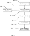
- FIG. 2 illustrates a method 200 of producing inhalable vapor.
- a vapor production device such as vapor production device 10 is loaded with a vapor vaporizable material, such as E-liquid.
- ambient air is delivered to heating center 24.
- the ambient air is delivered to the heater by way of air pump 22.
- the vaporizable material is heated to vaporize the material.
- Heating center 24 heats the vaporizable material to produce the vapor.
- the vapor is mixed with the supply of ambient air at block 208 and compressed at block 210.
- Compressor 26 is used to compress the mixture of ambient air and vapor.
- the compressed mixture of ambient air and vapor is then delivered to a suitable container at block 212, such as vapor container 12.
- kits comprising a vapor production device according to the invention and instructions for operating the vapor production device.
- the kit further comprises a container as described herein capable of storing pressurized vapor produced by the device.
Landscapes
- Health & Medical Sciences (AREA)
- Engineering & Computer Science (AREA)
- General Health & Medical Sciences (AREA)
- Public Health (AREA)
- Anesthesiology (AREA)
- Biomedical Technology (AREA)
- Heart & Thoracic Surgery (AREA)
- Hematology (AREA)
- Life Sciences & Earth Sciences (AREA)
- Animal Behavior & Ethology (AREA)
- Veterinary Medicine (AREA)
- Chemical & Material Sciences (AREA)
- Chemical Kinetics & Catalysis (AREA)
- General Chemical & Material Sciences (AREA)
- Pulmonology (AREA)
- General Engineering & Computer Science (AREA)
- Mechanical Engineering (AREA)
- Bioinformatics & Cheminformatics (AREA)
- Filling Or Discharging Of Gas Storage Vessels (AREA)
- Emergency Medicine (AREA)
- Manufacture Of Tobacco Products (AREA)
Description
- This disclosure relates generally to vaporizers, and more particularly to a vapor production system capable of storing vapor.
- Vaporizers have recently emerged as a new product for providing nicotine and other products through a smokeless inhalation process. There are many embodiments of vaporizers including the electronic cigarette. Most implementations consist of a power supply (typically a battery) and an atomizing device. In reusable electronic cigarettes the two items are separated into a battery and a cartomizer, to allow the disposal and replacement of the nicotine containing fluid cartomizer while preserving the more costly battery and associated circuitry (microcontroller, switch, indicating LED, etc.) In disposable electronic cigarettes the two items are combined to integrate the functions into one unit that is disposed of after either the battery energy or the nicotine containing E-liquid is exhausted. Vaporizers are generally designed to provide a supply of vapor on demand to a single user. In instances where multiple users are present, each user typically has their own vaporizer.
- The E-liquid that is used to produce vapor in electronic cigarettes is generally a solution of one or more of propylene glycol (PG) and/or vegetable glycerin (VG) and/or polyethylene glycol 400 (PEG400) mixed with concentrated flavors, and optionally, a variable percentage of a liquid nicotine concentrate. This liquid may be termed an "E-liquid" and is often sold in a bottle or in disposable cartridges or cartomizers. Many different flavors of such E-liquids are sold, including flavors that resemble the taste of regular tobacco, menthol, vanilla, coffee, cola and various fruits. Various nicotine concentrations are also available, and nicotine-free E-Liquids are also common.
-
US 2016331034 A1 describes an electronic vapor device comprising: a vapor outlet; a first container for storing a first vaporizable material, wherein the first container is permanently integrated into the electronic vapor device; a second container for storing a second vaporizable material, wherein the second container is removable from the electronic vapor device; a docking bay configured to receive the second container, wherein the second container is removed from or inserted into the docking bay through a door; and a vaporizer component configured for vaporizing the first vaporizable material or the second vaporizable material to generate a vapor and for providing the vapor to the vapor outlet.US 2016331034 discloses, in a separate embodiment: a vaporizer comprising a depressurization chamber, a vapor chamber, a first vapor conduit, a second vapor conduit, and a processor; and a container configured to hold a pre-vaporized liquid, under pressure, wherein the pre-vaporized liquid was generated, pressurized, and stored for later use; for example, a vaporizable element may be vaporized externally to the electronic vapor device; the vapor generated can be captured, compressed, and stored in the container; or, during the manufacture of the vaporizer, the vaporizable element may be created in the vaporizer device itself and compressed, and stored in the container; for example, an aerosol may be formed in carbon dioxide, compressed using equipment for compressing carbon dioxide, and stored in a cartridge suitable for carbon dioxide; in an alternative, pure carbon dioxide or other carrier gas may be pressurized and introduced into a cartridge that already contains a quantity of the material to be aerosolized, for example a powdered or liquid material. -
US 2014212517 discloses a device for capturing a component of a vapor, comprising a vaporizer and a vapor trap, the vapor trap in communication with a vaporizer outlet. The vaporizer has an air pump, an air inlet upstream of the air pump, an air heater in communication with the air pump, a vaporization chamber in communication with the air pump and downstream of the air heater, and a vaporizer outlet downstream of the vaporization chamber. In operation, a quantity of a vaporizing material is positioned within the vaporization chamber. The vapor trap forms an interior reservoir and has a vapor inlet and a vapor outlet positioned on opposite sides. A first container is positioned just downstream of the vapor inlet, which is configured to allow a vapor inlet flow and simultaneously prevent escape of the vapor trapping media through the vapor inlet. A second container is positioned just upstream of the vapor outlet, configured to allow a vapor outlet flow and simultaneously to prevent escape of the vapor trapping media through the vapor outlet. -
US 6513524 discloses a table-top apparatus with a seated receptacle and a valve as well as a vapor balloon. In the inside of a housing of the apparatus there is a hot air generator comprised of a motor, propeller, heat chamber and air flow tube which draws in the air from below through an air inlet provided in the base, heats and, following the laws of physics, in accordance with which heated air climbs upwards, conveys this upwards ("volcano"-smoke stack). Further there is situated on the outside of the housing a temperature regulator as well as an on/off switch. The receptacle includes a receptacle chamber in which either a plant material to be vaporized is loosely filled in or a crucible with a fluid to be vaporized is introduced. The receptacle further comprises a smoke detector to monitor the vapor upon the development of undesired smoke. The smoke detector provides a signal to a controller to regulate the temperature of the hot air source. The valve is comprised of a light metal block in which a valve cylinder and a valve spring wound on the outside of the valve cylinder are provided. The valve cylinder is rigidly connected with the valve cover via spacers. The openings between the spacers make it possible for the vapor to can travel into and out of the balloon while the valve is opened. Besides this the funnel shape itself insures for a perfect sealing when the valve is closed, and also holds the balloon securely in its place. The vapor balloon is comprised of a balloon jacket and a balloon retainer. Hot air is blown through the plant material and thereby the aroma- and active substances are transitioned into vapor, which is directed into the balloon via the valve and is collected there. The vapor can then be inhaled out of this balloon by means of a mouthpiece connected to the valve. - It is possible to draw the produced vapor/air mixture out of the balloon by means of a compressor for compressing and filling into a pressure container, or to directly fill the produced vapors via a compressor into a pressure container.
- According to the present invention, there is provided a vapor production device according to claim 1, a system according to claim 5, a method according to claim 8 and a kit according to
claim 10. Preferred embodiments of the invention are defined in the dependent claims 2-4, 6, 7, 9 and 11-13. -
-
FIG. 1 illustrates a schematic view of a vapor compression system according to an embodiment of the invention. -
FIG. 2 illustrates a flowchart of a method of producing inhalable vapor, according to an embodiment of the invention. -
FIG. 3 illustrates a storage container not being according to an embodiment of the invention. - The following detailed description and the appended drawings describe and illustrate some embodiments of the disclosure for the purpose of enabling one of ordinary skill in the relevant art to make and use these embodiments. As such, the detailed description and illustration of these embodiments are purely illustrative in nature and are in no way intended to limit the scope of the invention, which is defined by the claims. It should also be understood that the drawings are not necessarily to scale and in certain instances details may have been omitted, which are not necessary for an understanding of the embodiments, such as details of fabrication and assembly. In the accompanying drawings, like numerals represent like components.
-
FIG. 1 illustrates a schematic view of avapor production system 10.Vapor production system 10 is generally a system for producing compressed vapor suitable for filling acontainer 12 for later consumption by an end user. Once filled byvapor production system 10,container 12 may be used to consume vapor absent thevapor production system 10. Thus, vapor may be available in a setting that may not allow a traditional vaporizer, or in situations in which a high vapor production rate is required. -
Vapor production system 10 is contained within aportable case 14.Portable case 14 is powered by way of batteries, an external power source, or a combination of batteries and an external power system.Portable case 14 has an outer surface with aninlet 16 for receiving air, anoutlet 18 for produced vapor, andvaporizable material chamber 20 for receiving vaporizable material to be vaporized. Thevaporizable material chamber 20 may receive cartridges containing particular types of vaporizable materials, or it may receive the raw vaporizable materials to be vaporized. - Contained within
portable case 14 are components for producing vapor. Also contained within some embodiments of the vapor production system or its portable case are components for compressing vapor. In yet other embodiments, components for both producing vapor and for its compression are contained within the vapor production system or its portable case. As shown inFIG. 1 , the components includes anair pump 22, aheating center 24, avapor compressor 26, and acontrol panel 28. Additionally, each component is in fluid communication with adjacent components thoughair channels 30 with fluid flow between components controlled byvalves 32.Control panel 28 is wired to each component and one ormore valves 32 through common techniques as known by one of ordinary skill in the art. Dashedline 34 indicates the connection betweencontrol panel 28 and the components. -
Air pump 22 receives ambient air throughinlet 16.Inlet 16 may be connected directly toair pump 22, or as shown in the embodiment ofFIG. 1 ,inlet 16 may connect toair pump 22 by way ofair passage 32.Inlet 16 may have a filter suitable to prevent foreign material from enteringair pump 22.Air pump 22 may be any type of air pump as known in the art.Air pump 22 directs a volume of air thorough anair channel 30 toheating center 24. Afirst valve 32 is present inair channel 30 and prevents air from flowing intoheating center 24 fromair pump 22 when not in use.Valve 32 may be adjustable, to regulate the flow of air, or act as a simple on/off valve. -
Air channel 30 is in fluid communication withheating center 24.Heating center 24 has achamber 20 for receivingvaporizable material 21 and a heater for vaporizingvaporizable material 21.Heating center 24 heatsvaporizable material 21 to producevapor 23 as is known in the art. Air supplied throughair channel 30 mixes withvapor 23 to produce an inhalable vapor. - A
second air channel 30 directs inhalable vapor fromheating center 30 intovapor compressor 26.Vapor compressor 26 receives inhalable vapor, compresses it, and directs the compressed vapor tooutlet 18.Vapor container 12 is secured tooutlet 18 to receive the compressed vapor.Vapor container 12 may be attached, connected or secured toportable case 14 orvapor production system 10 during filling using common techniques such as a threaded connection or a twist lock connection. The compressed vapor contained within thevapor container 12 may then be used independently of thevapor production device 10. Additionally, the compressed vapor may be delivered at a much higher flow rate than what is available using a standard vaporizer. Because the vapor is compressed,vapor container 12 may hold a larger quantity than would otherwise be possible. -
Control panel 28 is configured to control the components of the vapor control system.Control panel 28 regulates the power delivered to theheating center 24 to convert the vaporizable material to vapor at a temperature suitable for its vaporization. The suitable temperature may be entered manually by an operator, orcontrol panel 28 may have stored data indicating an optimal temperature or heating profile. The quantity of air delivered toheating center 24 may be or is controlled by thecontrol panel 28 and may be adjusted in combination with the power delivered to the heating center for optimal vapor production.Compressor 26 is further controlled bycontrol panel 28 to deliver an optimal pressure for storage of the inhalable vapor. Depending on the type of vapor container and the vaporizable material being vaporized,compressor 26 regulates the level of compression to which the inhalable vapor is compressed. - Once
vapor container 12 is filled with vapor mixture to a desired pressure,vapor container 12 may be detached or otherwise disconnected fromportable case 14 orvapor production system 10. -
Vapor container 12 may be a small can shaped container having a neck for interfacing with thevapor production system 10, for example as illustrated inFIG. 3 . Materials of construction or design of the receiving container are not critical so long as the container can safely withstand the pressure level of vapor output fromsystem 10.Vapor container 12 is refillable and reusable. The container typically has abody 40 of sufficient durability and/or design to withstand pressures introduced during delivery of the compressed vapor. The container also has aconnector portion 42 configured to be compatible withoutlet 18. A vapor delivery device such as an inhalation tube or pipe may be connected to the neck of thevapor container 12. In other embodiments,vapor container 12 may have a separate connection ortube 44 for delivering pre-produced inhalation vapor. In certain other embodiments, the connection or tube for delivering pre-produced vapor may include avalve 46 or other regulating device to assist in delivery of vapor or to depressurize the container. In some embodiments, the interior of thevapor container 12 may be accessible for cleaning between fillings of different vaporizable materials. Alternatively, in other examples, thevapor container 12 may be sealed. - To prevent the vapor from condensing, or to reestablish the vapor properties within the container prior to inhalation, may require an establishing or maintenance of vapor temperature. To facilitate heat retention, the
vapor container 12 may be insulated to inhibit the loss of heat from thevapor container 12, maintaining its temperature without external heating. Alternatively,vapor container 12 may be actively heated to prevent vapor from condensing. Thevapor container 12 may have itsown controller 48 including an integratedheater 47 for controlling the temperature of the vapor. Typically the heater is configured to maintain a pressurized vapor in a vapor state. -
FIG. 2 illustrates amethod 200 of producing inhalable vapor. Inblock 202, a vapor production device according to the invention, such asvapor production device 10 is loaded with a vapor vaporizable material, such as E-liquid. Atblock 204, ambient air is delivered toheating center 24. The ambient air is delivered to the heater by way ofair pump 22. Atblock 206, the vaporizable material is heated to vaporize the material.Heating center 24 heats the vaporizable material to produce the vapor. The vapor is mixed with the supply of ambient air atblock 208 and compressed atblock 210.Compressor 26 is used to compress the mixture of ambient air and vapor. The compressed mixture of ambient air and vapor is then delivered to a suitable container atblock 212, such asvapor container 12. - Some embodiments of the present invention are directed to vapor production device kits comprising a vapor production device according to the invention and instructions for operating the vapor production device. In some embodiments, the kit further comprises a container as described herein capable of storing pressurized vapor produced by the device.
Claims (13)
- A vapor production device (10), comprising:an air inlet (16);an air pump (22) in fluid communication with the air inlet;a heating center (24) in fluid communication with the air pump, the heating center having:a chamber (20) configured to receive vaporizable material (21); anda heater;a compressor (26) in fluid communication with the heating center;an outlet (18) in fluid communication with the compressor; anda control panel (28),
wherein:the air pump (22) is configured to supply ambient air to the heating center;the heater is configured to heat the vaporizable material received in the chamber to a vaporization temperature to produce vaporized material;the heating center is configured to supply the ambient air supplied by the air pump and the vaporized material produced by the heater to the compressor (26);the compressor (26) is configured to compress the ambient air supplied by the heating center and the vaporized material supplied by the heating center to form a compressed mixture, and to deliver the formed mixture to the outlet;the outlet (18) is configured to deliver the compressed mixture delivered by the compressor to a storage container; andthe control panel is configured to regulate power delivered to the heating center to convert vaporizable material to vaporized material at a vaporization temperature, and to control the compressor to deliver an optimal pressure for storage of the vaporized material, such that the compressor (26) regulates a level of compression at which the compressed mixture is formed depending on a type of the storage container and a type of the vaporizable material. - The vapor production device according to claim 1, further comprising a supply of vaporizable material.
- The vapor production device according to any of claims 1-2, wherein the control panel (28) includes stored data indicating a heating profile.
- The vapor production device according to any of claims 1-3, wherein the control panel is configured to control a quantity of the ambient air supplied to the heating center.
- A system comprising:the vapor production device according to any of claims 1-2; anda storage container such that the outlet (18) of the vapor production device is configured to deliver the compressed mixture delivered by the compressor of the vapor production device to said storage container, wherein the storage container is suitable for storage of pressurized vapor produced by the vapor production device.
- The system according to claim 5, wherein the storage container is insulated.
- The system according to any of claims 5-6, wherein the storage container includes a heater configured to maintain a pressurized vapor stored in the storage container in a vapor state.
- A method for producing inhalable vapor, comprising:supplying a vaporizable material;loading the vaporizable material into the chamber of the heating center of a vapor production device according to claim 1;heating, with the heater of the heating center of the vapor production device, under the control of the control panel of the vapor production device, the loaded vaporizable material to a vaporization temperature to produce vaporized material;delivering, with the air pump of the vapor production device, ambient air to the heating center, so that the delivered ambient air is mixed with vaporized material produced by the heater;supplying the ambient air delivered to the heating center and the vaporized material produced by the heater to the compressor of the vapor production device;compressing, with the compressor of the vapor production device, under the control of the control panel of the vapor production device, the supplied ambient air and the supplied vaporized material to form a compressed mixture; anddelivering the compressed mixture to the device outlet of the vapor production device.
- The method for producing inhalable vapor according to claim 8, further comprising:
delivering, with the outlet of the vapor production device, the compressed mixture to a storage container for storage of said compressed vapor mixture. - A kit comprising:a vapor production device according to any of claims 1 to 4; andinstructions for operating the vapor production device.
- The kit according to claim 10, further comprising a storage container such that the outlet (18) of the vapor production device of the kit is configured to deliver the compressed mixture delivered by the compressor of the vapor production device of the kit to said storage container,
wherein the storage container is suitable for storage of pressurized vapor produced by the vapor production device. - The kit according to claim 11, wherein the storage container is insulated.
- The kit according to any of claims 11-12, wherein the storage container includes a storage container heater configured to maintain a pressurized vapor contained in said storage container in a vapor state.
Applications Claiming Priority (3)
| Application Number | Priority Date | Filing Date | Title |
|---|---|---|---|
| US201662433995P | 2016-12-14 | 2016-12-14 | |
| US201762485216P | 2017-04-13 | 2017-04-13 | |
| PCT/US2017/066367 WO2018112178A1 (en) | 2016-12-14 | 2017-12-14 | Vapor production device and method for producing inhalable vapor |
Publications (2)
| Publication Number | Publication Date |
|---|---|
| EP3554597A1 EP3554597A1 (en) | 2019-10-23 |
| EP3554597B1 true EP3554597B1 (en) | 2020-10-21 |
Family
ID=60937917
Family Applications (1)
| Application Number | Title | Priority Date | Filing Date |
|---|---|---|---|
| EP17826060.0A Active EP3554597B1 (en) | 2016-12-14 | 2017-12-14 | Vapor production device, system, method for producing inhalable vapor, and kit |
Country Status (8)
| Country | Link |
|---|---|
| US (1) | US20180160722A1 (en) |
| EP (1) | EP3554597B1 (en) |
| JP (1) | JP2020501559A (en) |
| KR (1) | KR20190105002A (en) |
| CN (1) | CN110198751A (en) |
| CA (1) | CA3046971A1 (en) |
| IL (1) | IL267228A (en) |
| WO (1) | WO2018112178A1 (en) |
Families Citing this family (3)
| Publication number | Priority date | Publication date | Assignee | Title |
|---|---|---|---|---|
| US11413409B2 (en) | 2018-09-12 | 2022-08-16 | Juul Labs, Inc. | Vaporizer including positive temperature coefficient of resistivity (PTCR) heating element |
| USD894371S1 (en) | 2019-03-01 | 2020-08-25 | Guardian Technologies Llc | Mist inhaler |
| EP3945885B1 (en) | 2019-03-29 | 2025-04-02 | Juul Labs, Inc. | Cartridges for vaporizer devices |
Family Cites Families (16)
| Publication number | Priority date | Publication date | Assignee | Title |
|---|---|---|---|---|
| US3211191A (en) * | 1955-02-04 | 1965-10-12 | Honisch Egon Johann | Apparatus for measuring a volatile liquid and for filling a container |
| US3266674A (en) * | 1964-08-24 | 1966-08-16 | Richard L Smith | Thermo-shave dispensing and reusable unit |
| AU3963078A (en) * | 1977-09-25 | 1980-03-13 | Kurio Medikaru Kk | Apparatus for refrigeration treatment |
| US4619297A (en) * | 1984-12-24 | 1986-10-28 | Kocher Kenneth E | Refillable pressure spray container |
| JP3084472B2 (en) * | 1994-11-21 | 2000-09-04 | セイコーインスツルメンツ株式会社 | Humidity control type thermal analyzer |
| US6382227B1 (en) * | 1997-05-09 | 2002-05-07 | The Boc Group, Inc. | Production of constant composition gas mixture streams |
| US6250301B1 (en) * | 1997-08-28 | 2001-06-26 | Hortal Harm B.V. | Vaporizer for inhalation and method for extraction of active ingredients from a crude natural product or other matrix |
| DE19803376C1 (en) * | 1998-01-29 | 1999-10-14 | Markus Storz | Inhaler for generating vapors containing aroma and / or active substances from plant material and / or liquids |
| FR2792210B1 (en) * | 1999-04-13 | 2001-09-14 | Air Liquide Sante Int | PORTABLE MEDICAL EQUIPMENT FOR OXYGEN THERAPY AT HOME |
| CA2617486A1 (en) * | 2005-08-08 | 2007-02-15 | Novartis Ag | Insulated canister for metered dose inhalers |
| RU2447906C2 (en) * | 2007-12-05 | 2012-04-20 | Джапан Тобакко Инк. | Aerosol inhaler |
| GB201118689D0 (en) * | 2011-10-28 | 2011-12-14 | Jt Int Sa | Apparatus for creating liquid tobacco extract |
| US9669326B2 (en) * | 2013-01-25 | 2017-06-06 | Geoff Todosiev | Vapor trap |
| US9016274B1 (en) * | 2013-10-14 | 2015-04-28 | Jackie L. White | Devices for vaporizing and delivering an aerosol agent |
| US20150305409A1 (en) * | 2013-11-12 | 2015-10-29 | VMR Products, LLC | Vaporizer |
| US10617150B2 (en) * | 2015-05-14 | 2020-04-14 | Lunatech, Llc | Vaporization method and apparatus |
-
2017
- 2017-12-14 WO PCT/US2017/066367 patent/WO2018112178A1/en not_active Ceased
- 2017-12-14 JP JP2019531793A patent/JP2020501559A/en active Pending
- 2017-12-14 US US15/842,042 patent/US20180160722A1/en not_active Abandoned
- 2017-12-14 CA CA3046971A patent/CA3046971A1/en active Pending
- 2017-12-14 EP EP17826060.0A patent/EP3554597B1/en active Active
- 2017-12-14 CN CN201780083291.7A patent/CN110198751A/en active Pending
- 2017-12-14 KR KR1020197019680A patent/KR20190105002A/en not_active Withdrawn
-
2019
- 2019-06-11 IL IL267228A patent/IL267228A/en unknown
Non-Patent Citations (1)
| Title |
|---|
| None * |
Also Published As
| Publication number | Publication date |
|---|---|
| US20180160722A1 (en) | 2018-06-14 |
| KR20190105002A (en) | 2019-09-11 |
| CA3046971A1 (en) | 2018-06-21 |
| WO2018112178A1 (en) | 2018-06-21 |
| EP3554597A1 (en) | 2019-10-23 |
| CN110198751A (en) | 2019-09-03 |
| JP2020501559A (en) | 2020-01-23 |
| IL267228A (en) | 2019-08-29 |
Similar Documents
| Publication | Publication Date | Title |
|---|---|---|
| EP3547861B1 (en) | Combination vaporizer | |
| EP3818871B1 (en) | Apparatus and system for generating aerosols | |
| US10893704B2 (en) | Vaporizer | |
| EP3600505B1 (en) | Portable device for inhalation of at least one active composition | |
| CN1630476B (en) | inhaler | |
| EP3504988A1 (en) | Non-combustion flavor inhaler | |
| US20160242467A1 (en) | Flavor module | |
| CN107846989A (en) | Gasification device | |
| US11000068B2 (en) | Aerosol inhalant producing device with measurable dose and/or other features | |
| CN110650641A (en) | Liquid Tobacco Extract | |
| CN107529830A (en) | For generating the barrel, part and method of inhalable medium | |
| EP3554597B1 (en) | Vapor production device, system, method for producing inhalable vapor, and kit | |
| CN109952040A (en) | Aerosol-generating system and method for dispensing a liquid aerosol-forming substrate by pumping air | |
| FR3064490A1 (en) | PORTABLE DEVICE FOR VAPORIZING AT LEAST ONE ACTIVE COMPOSITION | |
| HK40017690A (en) | Vapor production device, system, method for producing inhalable vapor, and kit | |
| HK40017690B (en) | Vapor production device, system, method for producing inhalable vapor, and kit | |
| US11503857B2 (en) | All-in-one grinder, heater, and inhalation apparatus | |
| EA038236B1 (en) | Vapor production device and method for producing inhalable vapor | |
| US12153060B2 (en) | Device and method for extracting and aspirating active substances, especially from the cannabis plant | |
| CA3125798C (en) | Device and method for extracting and aspirating active substances, especially from the cannabis plant | |
| HK40015987B (en) | Combination vaporizer | |
| HK40015987A (en) | Combination vaporizer | |
| CN119730737A (en) | Aerosol generating device |
Legal Events
| Date | Code | Title | Description |
|---|---|---|---|
| STAA | Information on the status of an ep patent application or granted ep patent |
Free format text: STATUS: UNKNOWN |
|
| STAA | Information on the status of an ep patent application or granted ep patent |
Free format text: STATUS: THE INTERNATIONAL PUBLICATION HAS BEEN MADE |
|
| PUAI | Public reference made under article 153(3) epc to a published international application that has entered the european phase |
Free format text: ORIGINAL CODE: 0009012 |
|
| STAA | Information on the status of an ep patent application or granted ep patent |
Free format text: STATUS: REQUEST FOR EXAMINATION WAS MADE |
|
| 17P | Request for examination filed |
Effective date: 20190618 |
|
| AK | Designated contracting states |
Kind code of ref document: A1 Designated state(s): AL AT BE BG CH CY CZ DE DK EE ES FI FR GB GR HR HU IE IS IT LI LT LU LV MC MK MT NL NO PL PT RO RS SE SI SK SM TR |
|
| AX | Request for extension of the european patent |
Extension state: BA ME |
|
| DAV | Request for validation of the european patent (deleted) | ||
| DAX | Request for extension of the european patent (deleted) | ||
| GRAP | Despatch of communication of intention to grant a patent |
Free format text: ORIGINAL CODE: EPIDOSNIGR1 |
|
| STAA | Information on the status of an ep patent application or granted ep patent |
Free format text: STATUS: GRANT OF PATENT IS INTENDED |
|
| RIC1 | Information provided on ipc code assigned before grant |
Ipc: A24F 40/00 20200101ALN20200324BHEP Ipc: A24F 47/00 20200101ALN20200324BHEP Ipc: A61M 16/00 20060101ALN20200324BHEP Ipc: A61M 15/00 20060101ALN20200324BHEP Ipc: A61M 11/04 20060101AFI20200324BHEP |
|
| INTG | Intention to grant announced |
Effective date: 20200421 |
|
| GRAS | Grant fee paid |
Free format text: ORIGINAL CODE: EPIDOSNIGR3 |
|
| GRAJ | Information related to disapproval of communication of intention to grant by the applicant or resumption of examination proceedings by the epo deleted |
Free format text: ORIGINAL CODE: EPIDOSDIGR1 |
|
| GRAL | Information related to payment of fee for publishing/printing deleted |
Free format text: ORIGINAL CODE: EPIDOSDIGR3 |
|
| STAA | Information on the status of an ep patent application or granted ep patent |
Free format text: STATUS: REQUEST FOR EXAMINATION WAS MADE |
|
| GRAR | Information related to intention to grant a patent recorded |
Free format text: ORIGINAL CODE: EPIDOSNIGR71 |
|
| STAA | Information on the status of an ep patent application or granted ep patent |
Free format text: STATUS: GRANT OF PATENT IS INTENDED |
|
| GRAA | (expected) grant |
Free format text: ORIGINAL CODE: 0009210 |
|
| STAA | Information on the status of an ep patent application or granted ep patent |
Free format text: STATUS: THE PATENT HAS BEEN GRANTED |
|
| REG | Reference to a national code |
Ref country code: HK Ref legal event code: DE Ref document number: 40017690 Country of ref document: HK |
|
| INTC | Intention to grant announced (deleted) | ||
| RIC1 | Information provided on ipc code assigned before grant |
Ipc: A24F 40/48 20200101ALN20200824BHEP Ipc: A61M 16/00 20060101ALN20200824BHEP Ipc: A61M 15/00 20060101ALN20200824BHEP Ipc: A61M 11/04 20060101AFI20200824BHEP Ipc: A24F 40/00 20200101ALN20200824BHEP |
|
| REG | Reference to a national code |
Ref country code: DE Ref legal event code: R082 Ref document number: 602017026079 Country of ref document: DE Representative=s name: WUESTHOFF & WUESTHOFF, PATENTANWAELTE PARTG MB, DE |
|
| AK | Designated contracting states |
Kind code of ref document: B1 Designated state(s): AL AT BE BG CH CY CZ DE DK EE ES FI FR GB GR HR HU IE IS IT LI LT LU LV MC MK MT NL NO PL PT RO RS SE SI SK SM TR |
|
| INTG | Intention to grant announced |
Effective date: 20200915 |
|
| REG | Reference to a national code |
Ref country code: GB Ref legal event code: FG4D |
|
| REG | Reference to a national code |
Ref country code: CH Ref legal event code: EP |
|
| REG | Reference to a national code |
Ref country code: IE Ref legal event code: FG4D |
|
| REG | Reference to a national code |
Ref country code: DE Ref legal event code: R096 Ref document number: 602017026079 Country of ref document: DE |
|
| REG | Reference to a national code |
Ref country code: AT Ref legal event code: REF Ref document number: 1325211 Country of ref document: AT Kind code of ref document: T Effective date: 20201115 |
|
| REG | Reference to a national code |
Ref country code: AT Ref legal event code: MK05 Ref document number: 1325211 Country of ref document: AT Kind code of ref document: T Effective date: 20201021 |
|
| REG | Reference to a national code |
Ref country code: NL Ref legal event code: MP Effective date: 20201021 |
|
| PG25 | Lapsed in a contracting state [announced via postgrant information from national office to epo] |
Ref country code: GR Free format text: LAPSE BECAUSE OF FAILURE TO SUBMIT A TRANSLATION OF THE DESCRIPTION OR TO PAY THE FEE WITHIN THE PRESCRIBED TIME-LIMIT Effective date: 20210122 Ref country code: NO Free format text: LAPSE BECAUSE OF FAILURE TO SUBMIT A TRANSLATION OF THE DESCRIPTION OR TO PAY THE FEE WITHIN THE PRESCRIBED TIME-LIMIT Effective date: 20210121 Ref country code: FI Free format text: LAPSE BECAUSE OF FAILURE TO SUBMIT A TRANSLATION OF THE DESCRIPTION OR TO PAY THE FEE WITHIN THE PRESCRIBED TIME-LIMIT Effective date: 20201021 Ref country code: RS Free format text: LAPSE BECAUSE OF FAILURE TO SUBMIT A TRANSLATION OF THE DESCRIPTION OR TO PAY THE FEE WITHIN THE PRESCRIBED TIME-LIMIT Effective date: 20201021 Ref country code: PT Free format text: LAPSE BECAUSE OF FAILURE TO SUBMIT A TRANSLATION OF THE DESCRIPTION OR TO PAY THE FEE WITHIN THE PRESCRIBED TIME-LIMIT Effective date: 20210222 |
|
| REG | Reference to a national code |
Ref country code: LT Ref legal event code: MG4D |
|
| PG25 | Lapsed in a contracting state [announced via postgrant information from national office to epo] |
Ref country code: BG Free format text: LAPSE BECAUSE OF FAILURE TO SUBMIT A TRANSLATION OF THE DESCRIPTION OR TO PAY THE FEE WITHIN THE PRESCRIBED TIME-LIMIT Effective date: 20210121 Ref country code: SE Free format text: LAPSE BECAUSE OF FAILURE TO SUBMIT A TRANSLATION OF THE DESCRIPTION OR TO PAY THE FEE WITHIN THE PRESCRIBED TIME-LIMIT Effective date: 20201021 Ref country code: PL Free format text: LAPSE BECAUSE OF FAILURE TO SUBMIT A TRANSLATION OF THE DESCRIPTION OR TO PAY THE FEE WITHIN THE PRESCRIBED TIME-LIMIT Effective date: 20201021 Ref country code: IS Free format text: LAPSE BECAUSE OF FAILURE TO SUBMIT A TRANSLATION OF THE DESCRIPTION OR TO PAY THE FEE WITHIN THE PRESCRIBED TIME-LIMIT Effective date: 20210221 Ref country code: LV Free format text: LAPSE BECAUSE OF FAILURE TO SUBMIT A TRANSLATION OF THE DESCRIPTION OR TO PAY THE FEE WITHIN THE PRESCRIBED TIME-LIMIT Effective date: 20201021 Ref country code: AT Free format text: LAPSE BECAUSE OF FAILURE TO SUBMIT A TRANSLATION OF THE DESCRIPTION OR TO PAY THE FEE WITHIN THE PRESCRIBED TIME-LIMIT Effective date: 20201021 Ref country code: ES Free format text: LAPSE BECAUSE OF FAILURE TO SUBMIT A TRANSLATION OF THE DESCRIPTION OR TO PAY THE FEE WITHIN THE PRESCRIBED TIME-LIMIT Effective date: 20201021 |
|
| PG25 | Lapsed in a contracting state [announced via postgrant information from national office to epo] |
Ref country code: NL Free format text: LAPSE BECAUSE OF FAILURE TO SUBMIT A TRANSLATION OF THE DESCRIPTION OR TO PAY THE FEE WITHIN THE PRESCRIBED TIME-LIMIT Effective date: 20201021 Ref country code: HR Free format text: LAPSE BECAUSE OF FAILURE TO SUBMIT A TRANSLATION OF THE DESCRIPTION OR TO PAY THE FEE WITHIN THE PRESCRIBED TIME-LIMIT Effective date: 20201021 |
|
| REG | Reference to a national code |
Ref country code: DE Ref legal event code: R097 Ref document number: 602017026079 Country of ref document: DE |
|
| PG25 | Lapsed in a contracting state [announced via postgrant information from national office to epo] |
Ref country code: SK Free format text: LAPSE BECAUSE OF FAILURE TO SUBMIT A TRANSLATION OF THE DESCRIPTION OR TO PAY THE FEE WITHIN THE PRESCRIBED TIME-LIMIT Effective date: 20201021 Ref country code: RO Free format text: LAPSE BECAUSE OF FAILURE TO SUBMIT A TRANSLATION OF THE DESCRIPTION OR TO PAY THE FEE WITHIN THE PRESCRIBED TIME-LIMIT Effective date: 20201021 Ref country code: SM Free format text: LAPSE BECAUSE OF FAILURE TO SUBMIT A TRANSLATION OF THE DESCRIPTION OR TO PAY THE FEE WITHIN THE PRESCRIBED TIME-LIMIT Effective date: 20201021 Ref country code: EE Free format text: LAPSE BECAUSE OF FAILURE TO SUBMIT A TRANSLATION OF THE DESCRIPTION OR TO PAY THE FEE WITHIN THE PRESCRIBED TIME-LIMIT Effective date: 20201021 Ref country code: CZ Free format text: LAPSE BECAUSE OF FAILURE TO SUBMIT A TRANSLATION OF THE DESCRIPTION OR TO PAY THE FEE WITHIN THE PRESCRIBED TIME-LIMIT Effective date: 20201021 Ref country code: LT Free format text: LAPSE BECAUSE OF FAILURE TO SUBMIT A TRANSLATION OF THE DESCRIPTION OR TO PAY THE FEE WITHIN THE PRESCRIBED TIME-LIMIT Effective date: 20201021 |
|
| REG | Reference to a national code |
Ref country code: CH Ref legal event code: PL |
|
| PLBE | No opposition filed within time limit |
Free format text: ORIGINAL CODE: 0009261 |
|
| STAA | Information on the status of an ep patent application or granted ep patent |
Free format text: STATUS: NO OPPOSITION FILED WITHIN TIME LIMIT |
|
| PG25 | Lapsed in a contracting state [announced via postgrant information from national office to epo] |
Ref country code: MC Free format text: LAPSE BECAUSE OF FAILURE TO SUBMIT A TRANSLATION OF THE DESCRIPTION OR TO PAY THE FEE WITHIN THE PRESCRIBED TIME-LIMIT Effective date: 20201021 Ref country code: DK Free format text: LAPSE BECAUSE OF FAILURE TO SUBMIT A TRANSLATION OF THE DESCRIPTION OR TO PAY THE FEE WITHIN THE PRESCRIBED TIME-LIMIT Effective date: 20201021 |
|
| REG | Reference to a national code |
Ref country code: BE Ref legal event code: MM Effective date: 20201231 |
|
| 26N | No opposition filed |
Effective date: 20210722 |
|
| REG | Reference to a national code |
Ref country code: DE Ref legal event code: R082 Ref document number: 602017026079 Country of ref document: DE Representative=s name: THUM, MOETSCH, WEICKERT PATENTANWAELTE PARTG M, DE Ref country code: DE Ref legal event code: R082 Ref document number: 602017026079 Country of ref document: DE Representative=s name: THUM & PARTNER THUM MOETSCH WEICKERT PATENTANW, DE |
|
| PG25 | Lapsed in a contracting state [announced via postgrant information from national office to epo] |
Ref country code: IE Free format text: LAPSE BECAUSE OF NON-PAYMENT OF DUE FEES Effective date: 20201214 Ref country code: AL Free format text: LAPSE BECAUSE OF FAILURE TO SUBMIT A TRANSLATION OF THE DESCRIPTION OR TO PAY THE FEE WITHIN THE PRESCRIBED TIME-LIMIT Effective date: 20201021 Ref country code: IT Free format text: LAPSE BECAUSE OF FAILURE TO SUBMIT A TRANSLATION OF THE DESCRIPTION OR TO PAY THE FEE WITHIN THE PRESCRIBED TIME-LIMIT Effective date: 20201021 Ref country code: LU Free format text: LAPSE BECAUSE OF NON-PAYMENT OF DUE FEES Effective date: 20201214 |
|
| PG25 | Lapsed in a contracting state [announced via postgrant information from national office to epo] |
Ref country code: SI Free format text: LAPSE BECAUSE OF FAILURE TO SUBMIT A TRANSLATION OF THE DESCRIPTION OR TO PAY THE FEE WITHIN THE PRESCRIBED TIME-LIMIT Effective date: 20201021 Ref country code: CH Free format text: LAPSE BECAUSE OF NON-PAYMENT OF DUE FEES Effective date: 20201231 Ref country code: LI Free format text: LAPSE BECAUSE OF NON-PAYMENT OF DUE FEES Effective date: 20201231 |
|
| PG25 | Lapsed in a contracting state [announced via postgrant information from national office to epo] |
Ref country code: IS Free format text: LAPSE BECAUSE OF FAILURE TO SUBMIT A TRANSLATION OF THE DESCRIPTION OR TO PAY THE FEE WITHIN THE PRESCRIBED TIME-LIMIT Effective date: 20210221 Ref country code: TR Free format text: LAPSE BECAUSE OF FAILURE TO SUBMIT A TRANSLATION OF THE DESCRIPTION OR TO PAY THE FEE WITHIN THE PRESCRIBED TIME-LIMIT Effective date: 20201021 Ref country code: MT Free format text: LAPSE BECAUSE OF FAILURE TO SUBMIT A TRANSLATION OF THE DESCRIPTION OR TO PAY THE FEE WITHIN THE PRESCRIBED TIME-LIMIT Effective date: 20201021 Ref country code: CY Free format text: LAPSE BECAUSE OF FAILURE TO SUBMIT A TRANSLATION OF THE DESCRIPTION OR TO PAY THE FEE WITHIN THE PRESCRIBED TIME-LIMIT Effective date: 20201021 |
|
| PG25 | Lapsed in a contracting state [announced via postgrant information from national office to epo] |
Ref country code: MK Free format text: LAPSE BECAUSE OF FAILURE TO SUBMIT A TRANSLATION OF THE DESCRIPTION OR TO PAY THE FEE WITHIN THE PRESCRIBED TIME-LIMIT Effective date: 20201021 |
|
| PG25 | Lapsed in a contracting state [announced via postgrant information from national office to epo] |
Ref country code: BE Free format text: LAPSE BECAUSE OF NON-PAYMENT OF DUE FEES Effective date: 20201231 |
|
| REG | Reference to a national code |
Ref country code: GB Ref legal event code: 732E Free format text: REGISTERED BETWEEN 20230209 AND 20230215 |
|
| REG | Reference to a national code |
Ref country code: GB Ref legal event code: 732E Free format text: REGISTERED BETWEEN 20230706 AND 20230712 |
|
| REG | Reference to a national code |
Ref country code: GB Ref legal event code: 732E Free format text: REGISTERED BETWEEN 20230713 AND 20230719 |
|
| REG | Reference to a national code |
Ref country code: GB Ref legal event code: 732E Free format text: REGISTERED BETWEEN 20231228 AND 20240103 |
|
| REG | Reference to a national code |
Ref country code: GB Ref legal event code: 732E Free format text: REGISTERED BETWEEN 20240411 AND 20240417 |
|
| REG | Reference to a national code |
Ref country code: GB Ref legal event code: 732E Free format text: REGISTERED BETWEEN 20240815 AND 20240821 |
|
| REG | Reference to a national code |
Ref country code: GB Ref legal event code: 732E Free format text: REGISTERED BETWEEN 20240905 AND 20240911 |
|
| REG | Reference to a national code |
Ref country code: GB Ref legal event code: 732E Free format text: REGISTERED BETWEEN 20251016 AND 20251022 |
|
| PGFP | Annual fee paid to national office [announced via postgrant information from national office to epo] |
Ref country code: DE Payment date: 20250930 Year of fee payment: 9 |
|
| PGFP | Annual fee paid to national office [announced via postgrant information from national office to epo] |
Ref country code: GB Payment date: 20251001 Year of fee payment: 9 |
|
| PGFP | Annual fee paid to national office [announced via postgrant information from national office to epo] |
Ref country code: FR Payment date: 20251008 Year of fee payment: 9 |
|
| REG | Reference to a national code |
Ref country code: GB Ref legal event code: 732E Free format text: REGISTERED BETWEEN 20260115 AND 20260121 |