EP3554597B1 - Dispositif de production de vapeur, système, procédé destiné à produire de la vapeur inhalable, et kit - Google Patents
Dispositif de production de vapeur, système, procédé destiné à produire de la vapeur inhalable, et kit Download PDFInfo
- Publication number
- EP3554597B1 EP3554597B1 EP17826060.0A EP17826060A EP3554597B1 EP 3554597 B1 EP3554597 B1 EP 3554597B1 EP 17826060 A EP17826060 A EP 17826060A EP 3554597 B1 EP3554597 B1 EP 3554597B1
- Authority
- EP
- European Patent Office
- Prior art keywords
- vapor
- production device
- storage container
- vapor production
- compressor
- Prior art date
- Legal status (The legal status is an assumption and is not a legal conclusion. Google has not performed a legal analysis and makes no representation as to the accuracy of the status listed.)
- Active
Links
- 238000004519 manufacturing process Methods 0.000 title claims description 48
- 239000003570 air Substances 0.000 claims description 45
- 239000000463 material Substances 0.000 claims description 33
- 238000003860 storage Methods 0.000 claims description 22
- 239000012080 ambient air Substances 0.000 claims description 14
- 239000000203 mixture Substances 0.000 claims description 14
- 230000008016 vaporization Effects 0.000 claims description 10
- 238000004891 communication Methods 0.000 claims description 9
- 239000012530 fluid Substances 0.000 claims description 9
- 238000009834 vaporization Methods 0.000 claims description 7
- 230000006835 compression Effects 0.000 claims description 4
- 238000007906 compression Methods 0.000 claims description 4
- 238000010438 heat treatment Methods 0.000 claims description 4
- 239000011364 vaporized material Substances 0.000 claims 9
- 239000006200 vaporizer Substances 0.000 description 11
- 239000007788 liquid Substances 0.000 description 10
- CURLTUGMZLYLDI-UHFFFAOYSA-N Carbon dioxide Chemical compound O=C=O CURLTUGMZLYLDI-UHFFFAOYSA-N 0.000 description 8
- DNIAPMSPPWPWGF-UHFFFAOYSA-N Propylene glycol Chemical compound CC(O)CO DNIAPMSPPWPWGF-UHFFFAOYSA-N 0.000 description 6
- 238000000034 method Methods 0.000 description 6
- SNICXCGAKADSCV-JTQLQIEISA-N (-)-Nicotine Chemical compound CN1CCC[C@H]1C1=CC=CN=C1 SNICXCGAKADSCV-JTQLQIEISA-N 0.000 description 5
- 229960002715 nicotine Drugs 0.000 description 5
- SNICXCGAKADSCV-UHFFFAOYSA-N nicotine Natural products CN1CCCC1C1=CC=CN=C1 SNICXCGAKADSCV-UHFFFAOYSA-N 0.000 description 5
- 229910002092 carbon dioxide Inorganic materials 0.000 description 4
- 239000001569 carbon dioxide Substances 0.000 description 4
- 239000003571 electronic cigarette Substances 0.000 description 4
- 239000000779 smoke Substances 0.000 description 4
- 239000000796 flavoring agent Substances 0.000 description 3
- 235000019634 flavors Nutrition 0.000 description 3
- 241000196324 Embryophyta Species 0.000 description 2
- PEDCQBHIVMGVHV-UHFFFAOYSA-N Glycerine Chemical compound OCC(O)CO PEDCQBHIVMGVHV-UHFFFAOYSA-N 0.000 description 2
- 238000013461 design Methods 0.000 description 2
- 238000003032 molecular docking Methods 0.000 description 2
- 229940068918 polyethylene glycol 400 Drugs 0.000 description 2
- 125000006850 spacer group Chemical group 0.000 description 2
- 238000011144 upstream manufacturing Methods 0.000 description 2
- NOOLISFMXDJSKH-UTLUCORTSA-N (+)-Neomenthol Chemical compound CC(C)[C@@H]1CC[C@@H](C)C[C@@H]1O NOOLISFMXDJSKH-UTLUCORTSA-N 0.000 description 1
- NOOLISFMXDJSKH-UHFFFAOYSA-N DL-menthol Natural products CC(C)C1CCC(C)CC1O NOOLISFMXDJSKH-UHFFFAOYSA-N 0.000 description 1
- 244000061176 Nicotiana tabacum Species 0.000 description 1
- 235000002637 Nicotiana tabacum Nutrition 0.000 description 1
- 229920002565 Polyethylene Glycol 400 Polymers 0.000 description 1
- 235000009499 Vanilla fragrans Nutrition 0.000 description 1
- 244000263375 Vanilla tahitensis Species 0.000 description 1
- 235000012036 Vanilla tahitensis Nutrition 0.000 description 1
- 239000013543 active substance Substances 0.000 description 1
- 239000000443 aerosol Substances 0.000 description 1
- 239000012159 carrier gas Substances 0.000 description 1
- 238000004140 cleaning Methods 0.000 description 1
- 239000012141 concentrate Substances 0.000 description 1
- 238000010276 construction Methods 0.000 description 1
- 230000001276 controlling effect Effects 0.000 description 1
- 230000001419 dependent effect Effects 0.000 description 1
- 238000011161 development Methods 0.000 description 1
- 235000013399 edible fruits Nutrition 0.000 description 1
- 235000011187 glycerol Nutrition 0.000 description 1
- 239000011344 liquid material Substances 0.000 description 1
- 238000012423 maintenance Methods 0.000 description 1
- 229940041616 menthol Drugs 0.000 description 1
- 239000002184 metal Substances 0.000 description 1
- 239000012254 powdered material Substances 0.000 description 1
- 230000001105 regulatory effect Effects 0.000 description 1
- 238000007789 sealing Methods 0.000 description 1
- CCEKAJIANROZEO-UHFFFAOYSA-N sulfluramid Chemical group CCNS(=O)(=O)C(F)(F)C(F)(F)C(F)(F)C(F)(F)C(F)(F)C(F)(F)C(F)(F)C(F)(F)F CCEKAJIANROZEO-UHFFFAOYSA-N 0.000 description 1
- 235000013311 vegetables Nutrition 0.000 description 1
Images

Classifications
-
- A—HUMAN NECESSITIES
- A24—TOBACCO; CIGARS; CIGARETTES; SIMULATED SMOKING DEVICES; SMOKERS' REQUISITES
- A24F—SMOKERS' REQUISITES; MATCH BOXES; SIMULATED SMOKING DEVICES
- A24F40/00—Electrically operated smoking devices; Component parts thereof; Manufacture thereof; Maintenance or testing thereof; Charging means specially adapted therefor
- A24F40/40—Constructional details, e.g. connection of cartridges and battery parts
- A24F40/48—Fluid transfer means, e.g. pumps
- A24F40/485—Valves; Apertures
-
- A—HUMAN NECESSITIES
- A24—TOBACCO; CIGARS; CIGARETTES; SIMULATED SMOKING DEVICES; SMOKERS' REQUISITES
- A24F—SMOKERS' REQUISITES; MATCH BOXES; SIMULATED SMOKING DEVICES
- A24F40/00—Electrically operated smoking devices; Component parts thereof; Manufacture thereof; Maintenance or testing thereof; Charging means specially adapted therefor
- A24F40/40—Constructional details, e.g. connection of cartridges and battery parts
- A24F40/48—Fluid transfer means, e.g. pumps
-
- A—HUMAN NECESSITIES
- A24—TOBACCO; CIGARS; CIGARETTES; SIMULATED SMOKING DEVICES; SMOKERS' REQUISITES
- A24B—MANUFACTURE OR PREPARATION OF TOBACCO FOR SMOKING OR CHEWING; TOBACCO; SNUFF
- A24B15/00—Chemical features or treatment of tobacco; Tobacco substitutes, e.g. in liquid form
- A24B15/10—Chemical features of tobacco products or tobacco substitutes
- A24B15/16—Chemical features of tobacco products or tobacco substitutes of tobacco substitutes
- A24B15/167—Chemical features of tobacco products or tobacco substitutes of tobacco substitutes in liquid or vaporisable form, e.g. liquid compositions for electronic cigarettes
-
- A—HUMAN NECESSITIES
- A24—TOBACCO; CIGARS; CIGARETTES; SIMULATED SMOKING DEVICES; SMOKERS' REQUISITES
- A24F—SMOKERS' REQUISITES; MATCH BOXES; SIMULATED SMOKING DEVICES
- A24F40/00—Electrically operated smoking devices; Component parts thereof; Manufacture thereof; Maintenance or testing thereof; Charging means specially adapted therefor
- A24F40/10—Devices using liquid inhalable precursors
-
- A—HUMAN NECESSITIES
- A24—TOBACCO; CIGARS; CIGARETTES; SIMULATED SMOKING DEVICES; SMOKERS' REQUISITES
- A24F—SMOKERS' REQUISITES; MATCH BOXES; SIMULATED SMOKING DEVICES
- A24F40/00—Electrically operated smoking devices; Component parts thereof; Manufacture thereof; Maintenance or testing thereof; Charging means specially adapted therefor
- A24F40/40—Constructional details, e.g. connection of cartridges and battery parts
- A24F40/42—Cartridges or containers for inhalable precursors
-
- A—HUMAN NECESSITIES
- A24—TOBACCO; CIGARS; CIGARETTES; SIMULATED SMOKING DEVICES; SMOKERS' REQUISITES
- A24F—SMOKERS' REQUISITES; MATCH BOXES; SIMULATED SMOKING DEVICES
- A24F40/00—Electrically operated smoking devices; Component parts thereof; Manufacture thereof; Maintenance or testing thereof; Charging means specially adapted therefor
- A24F40/40—Constructional details, e.g. connection of cartridges and battery parts
- A24F40/46—Shape or structure of electric heating means
-
- A—HUMAN NECESSITIES
- A61—MEDICAL OR VETERINARY SCIENCE; HYGIENE
- A61M—DEVICES FOR INTRODUCING MEDIA INTO, OR ONTO, THE BODY; DEVICES FOR TRANSDUCING BODY MEDIA OR FOR TAKING MEDIA FROM THE BODY; DEVICES FOR PRODUCING OR ENDING SLEEP OR STUPOR
- A61M11/00—Sprayers or atomisers specially adapted for therapeutic purposes
- A61M11/04—Sprayers or atomisers specially adapted for therapeutic purposes operated by the vapour pressure of the liquid to be sprayed or atomised
- A61M11/041—Sprayers or atomisers specially adapted for therapeutic purposes operated by the vapour pressure of the liquid to be sprayed or atomised using heaters
-
- A—HUMAN NECESSITIES
- A61—MEDICAL OR VETERINARY SCIENCE; HYGIENE
- A61M—DEVICES FOR INTRODUCING MEDIA INTO, OR ONTO, THE BODY; DEVICES FOR TRANSDUCING BODY MEDIA OR FOR TAKING MEDIA FROM THE BODY; DEVICES FOR PRODUCING OR ENDING SLEEP OR STUPOR
- A61M15/00—Inhalators
- A61M15/06—Inhaling appliances shaped like cigars, cigarettes or pipes
-
- F—MECHANICAL ENGINEERING; LIGHTING; HEATING; WEAPONS; BLASTING
- F17—STORING OR DISTRIBUTING GASES OR LIQUIDS
- F17C—VESSELS FOR CONTAINING OR STORING COMPRESSED, LIQUEFIED OR SOLIDIFIED GASES; FIXED-CAPACITY GAS-HOLDERS; FILLING VESSELS WITH, OR DISCHARGING FROM VESSELS, COMPRESSED, LIQUEFIED, OR SOLIDIFIED GASES
- F17C7/00—Methods or apparatus for discharging liquefied, solidified, or compressed gases from pressure vessels, not covered by another subclass
- F17C7/02—Discharging liquefied gases
- F17C7/04—Discharging liquefied gases with change of state, e.g. vaporisation
-
- H—ELECTRICITY
- H05—ELECTRIC TECHNIQUES NOT OTHERWISE PROVIDED FOR
- H05B—ELECTRIC HEATING; ELECTRIC LIGHT SOURCES NOT OTHERWISE PROVIDED FOR; CIRCUIT ARRANGEMENTS FOR ELECTRIC LIGHT SOURCES, IN GENERAL
- H05B1/00—Details of electric heating devices
- H05B1/02—Automatic switching arrangements specially adapted to apparatus ; Control of heating devices
- H05B1/0227—Applications
- H05B1/023—Industrial applications
- H05B1/0244—Heating of fluids
-
- A—HUMAN NECESSITIES
- A24—TOBACCO; CIGARS; CIGARETTES; SIMULATED SMOKING DEVICES; SMOKERS' REQUISITES
- A24F—SMOKERS' REQUISITES; MATCH BOXES; SIMULATED SMOKING DEVICES
- A24F40/00—Electrically operated smoking devices; Component parts thereof; Manufacture thereof; Maintenance or testing thereof; Charging means specially adapted therefor
-
- A—HUMAN NECESSITIES
- A61—MEDICAL OR VETERINARY SCIENCE; HYGIENE
- A61M—DEVICES FOR INTRODUCING MEDIA INTO, OR ONTO, THE BODY; DEVICES FOR TRANSDUCING BODY MEDIA OR FOR TAKING MEDIA FROM THE BODY; DEVICES FOR PRODUCING OR ENDING SLEEP OR STUPOR
- A61M15/00—Inhalators
- A61M15/009—Inhalators using medicine packages with incorporated spraying means, e.g. aerosol cans
-
- A—HUMAN NECESSITIES
- A61—MEDICAL OR VETERINARY SCIENCE; HYGIENE
- A61M—DEVICES FOR INTRODUCING MEDIA INTO, OR ONTO, THE BODY; DEVICES FOR TRANSDUCING BODY MEDIA OR FOR TAKING MEDIA FROM THE BODY; DEVICES FOR PRODUCING OR ENDING SLEEP OR STUPOR
- A61M16/00—Devices for influencing the respiratory system of patients by gas treatment, e.g. mouth-to-mouth respiration; Tracheal tubes
- A61M16/0057—Pumps therefor
- A61M16/0063—Compressors
-
- A—HUMAN NECESSITIES
- A61—MEDICAL OR VETERINARY SCIENCE; HYGIENE
- A61M—DEVICES FOR INTRODUCING MEDIA INTO, OR ONTO, THE BODY; DEVICES FOR TRANSDUCING BODY MEDIA OR FOR TAKING MEDIA FROM THE BODY; DEVICES FOR PRODUCING OR ENDING SLEEP OR STUPOR
- A61M2205/00—General characteristics of the apparatus
- A61M2205/33—Controlling, regulating or measuring
- A61M2205/3368—Temperature
-
- A—HUMAN NECESSITIES
- A61—MEDICAL OR VETERINARY SCIENCE; HYGIENE
- A61M—DEVICES FOR INTRODUCING MEDIA INTO, OR ONTO, THE BODY; DEVICES FOR TRANSDUCING BODY MEDIA OR FOR TAKING MEDIA FROM THE BODY; DEVICES FOR PRODUCING OR ENDING SLEEP OR STUPOR
- A61M2205/00—General characteristics of the apparatus
- A61M2205/36—General characteristics of the apparatus related to heating or cooling
- A61M2205/3653—General characteristics of the apparatus related to heating or cooling by Joule effect, i.e. electric resistance
-
- A—HUMAN NECESSITIES
- A61—MEDICAL OR VETERINARY SCIENCE; HYGIENE
- A61M—DEVICES FOR INTRODUCING MEDIA INTO, OR ONTO, THE BODY; DEVICES FOR TRANSDUCING BODY MEDIA OR FOR TAKING MEDIA FROM THE BODY; DEVICES FOR PRODUCING OR ENDING SLEEP OR STUPOR
- A61M2205/00—General characteristics of the apparatus
- A61M2205/50—General characteristics of the apparatus with microprocessors or computers
-
- A—HUMAN NECESSITIES
- A61—MEDICAL OR VETERINARY SCIENCE; HYGIENE
- A61M—DEVICES FOR INTRODUCING MEDIA INTO, OR ONTO, THE BODY; DEVICES FOR TRANSDUCING BODY MEDIA OR FOR TAKING MEDIA FROM THE BODY; DEVICES FOR PRODUCING OR ENDING SLEEP OR STUPOR
- A61M2209/00—Ancillary equipment
- A61M2209/04—Tools for specific apparatus
- A61M2209/045—Tools for specific apparatus for filling, e.g. for filling reservoirs
-
- F—MECHANICAL ENGINEERING; LIGHTING; HEATING; WEAPONS; BLASTING
- F17—STORING OR DISTRIBUTING GASES OR LIQUIDS
- F17C—VESSELS FOR CONTAINING OR STORING COMPRESSED, LIQUEFIED OR SOLIDIFIED GASES; FIXED-CAPACITY GAS-HOLDERS; FILLING VESSELS WITH, OR DISCHARGING FROM VESSELS, COMPRESSED, LIQUEFIED, OR SOLIDIFIED GASES
- F17C2227/00—Transfer of fluids, i.e. method or means for transferring the fluid; Heat exchange with the fluid
- F17C2227/03—Heat exchange with the fluid
- F17C2227/0367—Localisation of heat exchange
- F17C2227/0388—Localisation of heat exchange separate
- F17C2227/0393—Localisation of heat exchange separate using a vaporiser
-
- H—ELECTRICITY
- H05—ELECTRIC TECHNIQUES NOT OTHERWISE PROVIDED FOR
- H05B—ELECTRIC HEATING; ELECTRIC LIGHT SOURCES NOT OTHERWISE PROVIDED FOR; CIRCUIT ARRANGEMENTS FOR ELECTRIC LIGHT SOURCES, IN GENERAL
- H05B2203/00—Aspects relating to Ohmic resistive heating covered by group H05B3/00
- H05B2203/021—Heaters specially adapted for heating liquids
Definitions
- This disclosure relates generally to vaporizers, and more particularly to a vapor production system capable of storing vapor.
- Vaporizers have recently emerged as a new product for providing nicotine and other products through a smokeless inhalation process.
- vaporizers including the electronic cigarette.
- Most implementations consist of a power supply (typically a battery) and an atomizing device.
- a power supply typically a battery
- an atomizing device In reusable electronic cigarettes the two items are separated into a battery and a cartomizer, to allow the disposal and replacement of the nicotine containing fluid cartomizer while preserving the more costly battery and associated circuitry (microcontroller, switch, indicating LED, etc.)
- disposable electronic cigarettes the two items are combined to integrate the functions into one unit that is disposed of after either the battery energy or the nicotine containing E-liquid is exhausted.
- Vaporizers are generally designed to provide a supply of vapor on demand to a single user. In instances where multiple users are present, each user typically has their own vaporizer.
- the E-liquid that is used to produce vapor in electronic cigarettes is generally a solution of one or more of propylene glycol (PG) and/or vegetable glycerin (VG) and/or polyethylene glycol 400 (PEG400) mixed with concentrated flavors, and optionally, a variable percentage of a liquid nicotine concentrate.
- This liquid may be termed an "E-liquid” and is often sold in a bottle or in disposable cartridges or cartomizers.
- Many different flavors of such E-liquids are sold, including flavors that resemble the taste of regular tobacco, menthol, vanilla, coffee, cola and various fruits.
- Various nicotine concentrations are also available, and nicotine-free E-Liquids are also common.
- US 2016331034 A1 describes an electronic vapor device comprising: a vapor outlet; a first container for storing a first vaporizable material, wherein the first container is permanently integrated into the electronic vapor device; a second container for storing a second vaporizable material, wherein the second container is removable from the electronic vapor device; a docking bay configured to receive the second container, wherein the second container is removed from or inserted into the docking bay through a door; and a vaporizer component configured for vaporizing the first vaporizable material or the second vaporizable material to generate a vapor and for providing the vapor to the vapor outlet.
- US 2016331034 discloses, in a separate embodiment: a vaporizer comprising a depressurization chamber, a vapor chamber, a first vapor conduit, a second vapor conduit, and a processor; and a container configured to hold a pre-vaporized liquid, under pressure, wherein the pre-vaporized liquid was generated, pressurized, and stored for later use; for example, a vaporizable element may be vaporized externally to the electronic vapor device; the vapor generated can be captured, compressed, and stored in the container; or, during the manufacture of the vaporizer, the vaporizable element may be created in the vaporizer device itself and compressed, and stored in the container; for example, an aerosol may be formed in carbon dioxide, compressed using equipment for compressing carbon dioxide, and stored in a cartridge suitable for carbon dioxide; in an alternative, pure carbon dioxide or other carrier gas may be pressurized and introduced into a cartridge that already contains a quantity of the material to be aerosolized, for example a powdered or liquid material.
- US 2014212517 discloses a device for capturing a component of a vapor, comprising a vaporizer and a vapor trap, the vapor trap in communication with a vaporizer outlet.
- the vaporizer has an air pump, an air inlet upstream of the air pump, an air heater in communication with the air pump, a vaporization chamber in communication with the air pump and downstream of the air heater, and a vaporizer outlet downstream of the vaporization chamber.
- a quantity of a vaporizing material is positioned within the vaporization chamber.
- the vapor trap forms an interior reservoir and has a vapor inlet and a vapor outlet positioned on opposite sides.
- a first container is positioned just downstream of the vapor inlet, which is configured to allow a vapor inlet flow and simultaneously prevent escape of the vapor trapping media through the vapor inlet.
- a second container is positioned just upstream of the vapor outlet, configured to allow a vapor outlet flow and simultaneously to prevent escape of the vapor trapping media through the vapor outlet.
- US 6513524 discloses a table-top apparatus with a seated receptacle and a valve as well as a vapor balloon.
- a hot air generator comprised of a motor, propeller, heat chamber and air flow tube which draws in the air from below through an air inlet provided in the base, heats and, following the laws of physics, in accordance with which heated air climbs upwards, conveys this upwards (“volcano"-smoke stack).
- a temperature regulator as well as an on/off switch.
- the receptacle includes a receptacle chamber in which either a plant material to be vaporized is loosely filled in or a crucible with a fluid to be vaporized is introduced.
- the receptacle further comprises a smoke detector to monitor the vapor upon the development of undesired smoke.
- the smoke detector provides a signal to a controller to regulate the temperature of the hot air source.
- the valve is comprised of a light metal block in which a valve cylinder and a valve spring wound on the outside of the valve cylinder are provided.
- the valve cylinder is rigidly connected with the valve cover via spacers. The openings between the spacers make it possible for the vapor to can travel into and out of the balloon while the valve is opened.
- the funnel shape itself insures for a perfect sealing when the valve is closed, and also holds the balloon securely in its place.
- the vapor balloon is comprised of a balloon jacket and a balloon retainer. Hot air is blown through the plant material and thereby the aroma- and active substances are transitioned into vapor, which is directed into the balloon via the valve and is collected there. The vapor can then be inhaled out of this balloon by means of a mouthpiece connected to the valve.
- a vapor production device according to claim 1
- a system according to claim 5 a method according to claim 8 and a kit according to claim 10.
- Preferred embodiments of the invention are defined in the dependent claims 2-4, 6, 7, 9 and 11-13.
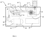
- FIG. 1 illustrates a schematic view of a vapor production system 10.
- Vapor production system 10 is generally a system for producing compressed vapor suitable for filling a container 12 for later consumption by an end user. Once filled by vapor production system 10, container 12 may be used to consume vapor absent the vapor production system 10. Thus, vapor may be available in a setting that may not allow a traditional vaporizer, or in situations in which a high vapor production rate is required.
- Vapor production system 10 is contained within a portable case 14.
- Portable case 14 is powered by way of batteries, an external power source, or a combination of batteries and an external power system.
- Portable case 14 has an outer surface with an inlet 16 for receiving air, an outlet 18 for produced vapor, and vaporizable material chamber 20 for receiving vaporizable material to be vaporized.
- the vaporizable material chamber 20 may receive cartridges containing particular types of vaporizable materials, or it may receive the raw vaporizable materials to be vaporized.
- the components Contained within portable case 14 are components for producing vapor. Also contained within some embodiments of the vapor production system or its portable case are components for compressing vapor. In yet other embodiments, components for both producing vapor and for its compression are contained within the vapor production system or its portable case. As shown in FIG. 1 , the components includes an air pump 22, a heating center 24, a vapor compressor 26, and a control panel 28. Additionally, each component is in fluid communication with adjacent components though air channels 30 with fluid flow between components controlled by valves 32. Control panel 28 is wired to each component and one or more valves 32 through common techniques as known by one of ordinary skill in the art. Dashed line 34 indicates the connection between control panel 28 and the components.
- Air pump 22 receives ambient air through inlet 16.
- Inlet 16 may be connected directly to air pump 22, or as shown in the embodiment of FIG. 1 , inlet 16 may connect to air pump 22 by way of air passage 32.
- Inlet 16 may have a filter suitable to prevent foreign material from entering air pump 22.
- Air pump 22 may be any type of air pump as known in the art. Air pump 22 directs a volume of air thorough an air channel 30 to heating center 24. A first valve 32 is present in air channel 30 and prevents air from flowing into heating center 24 from air pump 22 when not in use. Valve 32 may be adjustable, to regulate the flow of air, or act as a simple on/off valve.
- Air channel 30 is in fluid communication with heating center 24.
- Heating center 24 has a chamber 20 for receiving vaporizable material 21 and a heater for vaporizing vaporizable material 21. Heating center 24 heats vaporizable material 21 to produce vapor 23 as is known in the art. Air supplied through air channel 30 mixes with vapor 23 to produce an inhalable vapor.
- a second air channel 30 directs inhalable vapor from heating center 30 into vapor compressor 26.
- Vapor compressor 26 receives inhalable vapor, compresses it, and directs the compressed vapor to outlet 18.
- Vapor container 12 is secured to outlet 18 to receive the compressed vapor.
- Vapor container 12 may be attached, connected or secured to portable case 14 or vapor production system 10 during filling using common techniques such as a threaded connection or a twist lock connection.
- the compressed vapor contained within the vapor container 12 may then be used independently of the vapor production device 10. Additionally, the compressed vapor may be delivered at a much higher flow rate than what is available using a standard vaporizer. Because the vapor is compressed, vapor container 12 may hold a larger quantity than would otherwise be possible.
- Control panel 28 is configured to control the components of the vapor control system. Control panel 28 regulates the power delivered to the heating center 24 to convert the vaporizable material to vapor at a temperature suitable for its vaporization. The suitable temperature may be entered manually by an operator, or control panel 28 may have stored data indicating an optimal temperature or heating profile. The quantity of air delivered to heating center 24 may be or is controlled by the control panel 28 and may be adjusted in combination with the power delivered to the heating center for optimal vapor production. Compressor 26 is further controlled by control panel 28 to deliver an optimal pressure for storage of the inhalable vapor. Depending on the type of vapor container and the vaporizable material being vaporized, compressor 26 regulates the level of compression to which the inhalable vapor is compressed.
- vapor container 12 Once vapor container 12 is filled with vapor mixture to a desired pressure, vapor container 12 may be detached or otherwise disconnected from portable case 14 or vapor production system 10.
- Vapor container 12 may be a small can shaped container having a neck for interfacing with the vapor production system 10, for example as illustrated in FIG. 3 .
- Materials of construction or design of the receiving container are not critical so long as the container can safely withstand the pressure level of vapor output from system 10.
- Vapor container 12 is refillable and reusable.
- the container typically has a body 40 of sufficient durability and/or design to withstand pressures introduced during delivery of the compressed vapor.
- the container also has a connector portion 42 configured to be compatible with outlet 18.
- a vapor delivery device such as an inhalation tube or pipe may be connected to the neck of the vapor container 12.
- vapor container 12 may have a separate connection or tube 44 for delivering pre-produced inhalation vapor.
- connection or tube for delivering pre-produced vapor may include a valve 46 or other regulating device to assist in delivery of vapor or to depressurize the container.
- the interior of the vapor container 12 may be accessible for cleaning between fillings of different vaporizable materials.
- the vapor container 12 may be sealed.
- the vapor container 12 may be insulated to inhibit the loss of heat from the vapor container 12, maintaining its temperature without external heating. Alternatively, vapor container 12 may be actively heated to prevent vapor from condensing.
- the vapor container 12 may have its own controller 48 including an integrated heater 47 for controlling the temperature of the vapor. Typically the heater is configured to maintain a pressurized vapor in a vapor state.
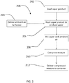
- FIG. 2 illustrates a method 200 of producing inhalable vapor.
- a vapor production device such as vapor production device 10 is loaded with a vapor vaporizable material, such as E-liquid.
- ambient air is delivered to heating center 24.
- the ambient air is delivered to the heater by way of air pump 22.
- the vaporizable material is heated to vaporize the material.
- Heating center 24 heats the vaporizable material to produce the vapor.
- the vapor is mixed with the supply of ambient air at block 208 and compressed at block 210.
- Compressor 26 is used to compress the mixture of ambient air and vapor.
- the compressed mixture of ambient air and vapor is then delivered to a suitable container at block 212, such as vapor container 12.
- kits comprising a vapor production device according to the invention and instructions for operating the vapor production device.
- the kit further comprises a container as described herein capable of storing pressurized vapor produced by the device.
Claims (13)
- Dispositif (10) de production de vapeur, comprenant :une entrée d'air (16) ;une pompe à air (22) en communication de fluide avec l'entrée d'air ;un centre de chauffage (24) en communication de fluide avec la pompe à air, le centre de chauffage ayant : une chambre (20) configurée pour recevoir une matière vaporisable (21) ; et un dispositif de chauffage ;un compresseur (26) en communication de fluide avec le centre de chauffage ;une sortie (18) en communication de fluide avec le compresseur ; etun panneau de commande (28),
dans lequel :la pompe à air (22) est configurée pour fournir l'air ambiant au centre de chauffage ;le dispositif de chauffage est configuré pour chauffer la matière vaporisable reçue dans la chambre jusqu'à une température de vaporisation pour produire une matière vaporisée ;le centre de chauffage est configuré pour fournir l'air ambiant fourni par la pompe à air et la matière vaporisée produite par le dispositif de chauffage au compresseur (26) ;le compresseur (26) est configuré pour comprimer l'air ambiant fourni par le centre de chauffage et la matière vaporisée fournie par le centre de chauffage pour former un mélange comprimé, et pour envoyer le mélange formé jusqu'à la sortie ;la sortie (18) est configurée pour envoyer le mélange comprimé envoyé par le compresseur jusqu'à un réservoir de stockage ; etle panneau de commande est configuré pour réguler une énergie envoyée jusqu'au centre de chauffage pour convertir la matière vaporisable en matière vaporisée à une température de vaporisation, et pour commander le compresseur pour fournir une pression optimale pour le stockage de la matière vaporisée, de telle sorte que le compresseur (26) régule un niveau de compression auquel le mélange comprimé est formé en fonction d'un type du réservoir de stockage et d'un type de la matière vaporisable. - Dispositif de production de vapeur selon la revendication 1, comprenant en outre une alimentation de matière vaporisable.
- Dispositif de production de vapeur selon l'une quelconque des revendications 1 à 2, dans lequel le panneau de commande (28) inclut des données stockées indiquant un profil de chauffage.
- Dispositif de production de vapeur selon l'une quelconque des revendications 1 à 3, dans lequel le panneau de commande est configuré pour commander une quantité de l'air ambiant fournie au centre de chauffage.
- Système comprenant :le dispositif de production de vapeur selon l'une quelconque des revendications 1 à 2 ; etun réservoir de stockage tel que la sortie (18) du dispositif de production de vapeur est configurée pour envoyer le mélange comprimé envoyé par le compresseur du dispositif de production de vapeur jusqu'audit réservoir de stockage, dans lequel le réservoir de stockage est approprié au stockage de la vapeur sous pression produite par le dispositif de production de vapeur.
- Système selon la revendication 5, dans lequel le réservoir de stockage est isolé.
- Système selon l'une quelconque des revendications 5 à 6, dans lequel le réservoir de stockage inclut un dispositif de chauffage configuré pour maintenir une vapeur sous pression stockée dans le réservoir de stockage dans un état de vapeur.
- Procédé pour produire une vapeur inhalable, comprenant :la fourniture d'une matière vaporisable ;le chargement de la matière vaporisable dans la chambre du centre de chauffage d'un dispositif de production de vapeur selon la revendication 1 ;le chauffage, avec le dispositif de chauffage du centre de chauffage du dispositif de production de vapeur, sous le contrôle du panneau de commande du dispositif de production de vapeur, de la matière vaporisable chargée jusqu'à une température de vaporisation pour produire une matière vaporisée ;l'envoi, avec la pompe à air du dispositif de production de vapeur, d'air ambiant jusqu'au centre de chauffage, de telle sorte que l'air ambiant envoyé est mélangé avec la matière vaporisée produite par le dispositif de chauffage ;la fourniture de l'air ambiant envoyé au centre de chauffage et de la matière vaporisée produite par le dispositif de chauffage au compresseur du dispositif de production de vapeur ;la compression, avec le compresseur du dispositif de production de vapeur, sous le contrôle du panneau de commande du dispositif de production de vapeur, de l'air ambiant fourni et de la matière vaporisée fournie pour former un mélange comprimé ; etl'envoi du mélange comprimé à la sortie de dispositif du dispositif de production de vapeur.
- Procédé pour produire une vapeur inhalable selon la revendication 8, comprenant en outre :
l'envoi, avec la sortie du dispositif de production de vapeur, du mélange comprimé jusqu'à un réservoir de stockage pour stockage dudit mélange de vapeur comprimé. - Trousse comprenant :un dispositif de production de vapeur selon l'une quelconque des revendications 1 à 4 ; etdes instructions pour utiliser le dispositif de production de vapeur.
- Trousse selon la revendication 10, comprenant en outre un réservoir de stockage tel que la sortie (18) du dispositif de production de vapeur de la trousse est configurée pour envoyer le mélange comprimé envoyé par le compresseur du dispositif de production de vapeur de la trousse jusqu'audit réservoir de stockage, dans lequel le réservoir de stockage est approprié au stockage de la vapeur sous pression produite par le dispositif de production de vapeur.
- Trousse selon la revendication 11 dans lequel le réservoir de stockage est isolé.
- Trousse selon l'une quelconque des revendications 11 à 12, dans lequel le réservoir de stockage inclut un dispositif de chauffage de réservoir de stockage configuré pour maintenir une vapeur sous pression stockée dans ledit réservoir de stockage dans un état de vapeur.
Applications Claiming Priority (3)
| Application Number | Priority Date | Filing Date | Title |
|---|---|---|---|
| US201662433995P | 2016-12-14 | 2016-12-14 | |
| US201762485216P | 2017-04-13 | 2017-04-13 | |
| PCT/US2017/066367 WO2018112178A1 (fr) | 2016-12-14 | 2017-12-14 | Dispositif de production de vapeur et procédé destiné à produire de la vapeur inhalable |
Publications (2)
| Publication Number | Publication Date |
|---|---|
| EP3554597A1 EP3554597A1 (fr) | 2019-10-23 |
| EP3554597B1 true EP3554597B1 (fr) | 2020-10-21 |
Family
ID=60937917
Family Applications (1)
| Application Number | Title | Priority Date | Filing Date |
|---|---|---|---|
| EP17826060.0A Active EP3554597B1 (fr) | 2016-12-14 | 2017-12-14 | Dispositif de production de vapeur, système, procédé destiné à produire de la vapeur inhalable, et kit |
Country Status (8)
| Country | Link |
|---|---|
| US (1) | US20180160722A1 (fr) |
| EP (1) | EP3554597B1 (fr) |
| JP (1) | JP2020501559A (fr) |
| KR (1) | KR20190105002A (fr) |
| CN (1) | CN110198751A (fr) |
| CA (1) | CA3046971A1 (fr) |
| IL (1) | IL267228A (fr) |
| WO (1) | WO2018112178A1 (fr) |
Families Citing this family (2)
| Publication number | Priority date | Publication date | Assignee | Title |
|---|---|---|---|---|
| US11413409B2 (en) | 2018-09-12 | 2022-08-16 | Juul Labs, Inc. | Vaporizer including positive temperature coefficient of resistivity (PTCR) heating element |
| USD894371S1 (en) | 2019-03-01 | 2020-08-25 | Guardian Technologies Llc | Mist inhaler |
Family Cites Families (16)
| Publication number | Priority date | Publication date | Assignee | Title |
|---|---|---|---|---|
| US3211191A (en) * | 1955-02-04 | 1965-10-12 | Honisch Egon Johann | Apparatus for measuring a volatile liquid and for filling a container |
| US3266674A (en) * | 1964-08-24 | 1966-08-16 | Richard L Smith | Thermo-shave dispensing and reusable unit |
| AU3963078A (en) * | 1977-09-25 | 1980-03-13 | Kurio Medikaru Kk | Apparatus for refrigeration treatment |
| US4619297A (en) * | 1984-12-24 | 1986-10-28 | Kocher Kenneth E | Refillable pressure spray container |
| JP3084472B2 (ja) * | 1994-11-21 | 2000-09-04 | セイコーインスツルメンツ株式会社 | 湿度制御式熱分析装置 |
| US6382227B1 (en) * | 1997-05-09 | 2002-05-07 | The Boc Group, Inc. | Production of constant composition gas mixture streams |
| US6250301B1 (en) * | 1997-08-28 | 2001-06-26 | Hortal Harm B.V. | Vaporizer for inhalation and method for extraction of active ingredients from a crude natural product or other matrix |
| DE19803376C1 (de) * | 1998-01-29 | 1999-10-14 | Markus Storz | Inhalator zur Erzeugung von aroma- und/oder wirkstoffhaltigen Dämpfen aus Pflanzenmaterial und/oder Flüssigkeiten |
| FR2792210B1 (fr) * | 1999-04-13 | 2001-09-14 | Air Liquide Sante Int | Equipement medical portable d'oxygenotherapie a domicile |
| CN101238047B (zh) * | 2005-08-08 | 2010-06-16 | 诺瓦提斯公司 | 用于定量吸入器的隔热筒罐 |
| RU2447906C2 (ru) * | 2007-12-05 | 2012-04-20 | Джапан Тобакко Инк. | Аэрозольный ингалятор |
| GB201118689D0 (en) * | 2011-10-28 | 2011-12-14 | Jt Int Sa | Apparatus for creating liquid tobacco extract |
| US9669326B2 (en) * | 2013-01-25 | 2017-06-06 | Geoff Todosiev | Vapor trap |
| US9016274B1 (en) * | 2013-10-14 | 2015-04-28 | Jackie L. White | Devices for vaporizing and delivering an aerosol agent |
| US20150305409A1 (en) * | 2013-11-12 | 2015-10-29 | VMR Products, LLC | Vaporizer |
| US10617150B2 (en) * | 2015-05-14 | 2020-04-14 | Lunatech, Llc | Vaporization method and apparatus |
-
2017
- 2017-12-14 JP JP2019531793A patent/JP2020501559A/ja active Pending
- 2017-12-14 KR KR1020197019680A patent/KR20190105002A/ko unknown
- 2017-12-14 CA CA3046971A patent/CA3046971A1/fr active Pending
- 2017-12-14 EP EP17826060.0A patent/EP3554597B1/fr active Active
- 2017-12-14 CN CN201780083291.7A patent/CN110198751A/zh active Pending
- 2017-12-14 US US15/842,042 patent/US20180160722A1/en not_active Abandoned
- 2017-12-14 WO PCT/US2017/066367 patent/WO2018112178A1/fr unknown
-
2019
- 2019-06-11 IL IL267228A patent/IL267228A/en unknown
Non-Patent Citations (1)
| Title |
|---|
| None * |
Also Published As
| Publication number | Publication date |
|---|---|
| US20180160722A1 (en) | 2018-06-14 |
| JP2020501559A (ja) | 2020-01-23 |
| KR20190105002A (ko) | 2019-09-11 |
| CA3046971A1 (fr) | 2018-06-21 |
| WO2018112178A1 (fr) | 2018-06-21 |
| IL267228A (en) | 2019-08-29 |
| EP3554597A1 (fr) | 2019-10-23 |
| CN110198751A (zh) | 2019-09-03 |
Similar Documents
| Publication | Publication Date | Title |
|---|---|---|
| EP3547861B1 (fr) | Vaporisateur combiné | |
| US11889862B2 (en) | Apparatus and system for generating aerosols | |
| EP3600505B1 (fr) | Dispositif portable d'inhalation d'au moins une composition active | |
| US10893704B2 (en) | Vaporizer | |
| KR102435118B1 (ko) | 다수의 분산액 발생기 e-베이핑 장치 | |
| CN107846989B (zh) | 气化装置 | |
| CA3033621C (fr) | Inhalateur d'arome sans combustion | |
| JP6925986B2 (ja) | エアロゾル形成組成物の製造 | |
| US20160242467A1 (en) | Flavor module | |
| US11000068B2 (en) | Aerosol inhalant producing device with measurable dose and/or other features | |
| RU2311859C2 (ru) | Ингалятор | |
| EP3554597B1 (fr) | Dispositif de production de vapeur, système, procédé destiné à produire de la vapeur inhalable, et kit | |
| JP2018143765A (ja) | 吸入器のための蒸発器ユニット | |
| US20220095681A1 (en) | Device and method for extracting and aspirating active substances, especially from the cannabis plant | |
| FR3064490A1 (fr) | Dispositif portable de vaporisation d'au moins une composition active | |
| WO2020161289A1 (fr) | Dispositif à fumer de substitution | |
| EA038236B1 (ru) | Устройство получения пара и способ получения ингалируемого пара | |
| EP3920739B1 (fr) | Appareil de substitution au tabac | |
| US11503857B2 (en) | All-in-one grinder, heater, and inhalation apparatus | |
| EA039233B1 (ru) | Испаритель комбинации |
Legal Events
| Date | Code | Title | Description |
|---|---|---|---|
| STAA | Information on the status of an ep patent application or granted ep patent |
Free format text: STATUS: UNKNOWN |
|
| STAA | Information on the status of an ep patent application or granted ep patent |
Free format text: STATUS: THE INTERNATIONAL PUBLICATION HAS BEEN MADE |
|
| PUAI | Public reference made under article 153(3) epc to a published international application that has entered the european phase |
Free format text: ORIGINAL CODE: 0009012 |
|
| STAA | Information on the status of an ep patent application or granted ep patent |
Free format text: STATUS: REQUEST FOR EXAMINATION WAS MADE |
|
| 17P | Request for examination filed |
Effective date: 20190618 |
|
| AK | Designated contracting states |
Kind code of ref document: A1 Designated state(s): AL AT BE BG CH CY CZ DE DK EE ES FI FR GB GR HR HU IE IS IT LI LT LU LV MC MK MT NL NO PL PT RO RS SE SI SK SM TR |
|
| AX | Request for extension of the european patent |
Extension state: BA ME |
|
| DAV | Request for validation of the european patent (deleted) | ||
| DAX | Request for extension of the european patent (deleted) | ||
| GRAP | Despatch of communication of intention to grant a patent |
Free format text: ORIGINAL CODE: EPIDOSNIGR1 |
|
| STAA | Information on the status of an ep patent application or granted ep patent |
Free format text: STATUS: GRANT OF PATENT IS INTENDED |
|
| RIC1 | Information provided on ipc code assigned before grant |
Ipc: A24F 40/00 20200101ALN20200324BHEP Ipc: A24F 47/00 20200101ALN20200324BHEP Ipc: A61M 16/00 20060101ALN20200324BHEP Ipc: A61M 15/00 20060101ALN20200324BHEP Ipc: A61M 11/04 20060101AFI20200324BHEP |
|
| INTG | Intention to grant announced |
Effective date: 20200421 |
|
| GRAS | Grant fee paid |
Free format text: ORIGINAL CODE: EPIDOSNIGR3 |
|
| GRAJ | Information related to disapproval of communication of intention to grant by the applicant or resumption of examination proceedings by the epo deleted |
Free format text: ORIGINAL CODE: EPIDOSDIGR1 |
|
| GRAL | Information related to payment of fee for publishing/printing deleted |
Free format text: ORIGINAL CODE: EPIDOSDIGR3 |
|
| STAA | Information on the status of an ep patent application or granted ep patent |
Free format text: STATUS: REQUEST FOR EXAMINATION WAS MADE |
|
| GRAR | Information related to intention to grant a patent recorded |
Free format text: ORIGINAL CODE: EPIDOSNIGR71 |
|
| STAA | Information on the status of an ep patent application or granted ep patent |
Free format text: STATUS: GRANT OF PATENT IS INTENDED |
|
| GRAA | (expected) grant |
Free format text: ORIGINAL CODE: 0009210 |
|
| STAA | Information on the status of an ep patent application or granted ep patent |
Free format text: STATUS: THE PATENT HAS BEEN GRANTED |
|
| REG | Reference to a national code |
Ref country code: HK Ref legal event code: DE Ref document number: 40017690 Country of ref document: HK |
|
| INTC | Intention to grant announced (deleted) | ||
| RIC1 | Information provided on ipc code assigned before grant |
Ipc: A24F 40/48 20200101ALN20200824BHEP Ipc: A61M 16/00 20060101ALN20200824BHEP Ipc: A61M 15/00 20060101ALN20200824BHEP Ipc: A61M 11/04 20060101AFI20200824BHEP Ipc: A24F 40/00 20200101ALN20200824BHEP |
|
| REG | Reference to a national code |
Ref country code: DE Ref legal event code: R082 Ref document number: 602017026079 Country of ref document: DE Representative=s name: WUESTHOFF & WUESTHOFF, PATENTANWAELTE PARTG MB, DE |
|
| AK | Designated contracting states |
Kind code of ref document: B1 Designated state(s): AL AT BE BG CH CY CZ DE DK EE ES FI FR GB GR HR HU IE IS IT LI LT LU LV MC MK MT NL NO PL PT RO RS SE SI SK SM TR |
|
| INTG | Intention to grant announced |
Effective date: 20200915 |
|
| REG | Reference to a national code |
Ref country code: GB Ref legal event code: FG4D |
|
| REG | Reference to a national code |
Ref country code: CH Ref legal event code: EP |
|
| REG | Reference to a national code |
Ref country code: IE Ref legal event code: FG4D |
|
| REG | Reference to a national code |
Ref country code: DE Ref legal event code: R096 Ref document number: 602017026079 Country of ref document: DE |
|
| REG | Reference to a national code |
Ref country code: AT Ref legal event code: REF Ref document number: 1325211 Country of ref document: AT Kind code of ref document: T Effective date: 20201115 |
|
| REG | Reference to a national code |
Ref country code: AT Ref legal event code: MK05 Ref document number: 1325211 Country of ref document: AT Kind code of ref document: T Effective date: 20201021 |
|
| REG | Reference to a national code |
Ref country code: NL Ref legal event code: MP Effective date: 20201021 |
|
| PG25 | Lapsed in a contracting state [announced via postgrant information from national office to epo] |
Ref country code: GR Free format text: LAPSE BECAUSE OF FAILURE TO SUBMIT A TRANSLATION OF THE DESCRIPTION OR TO PAY THE FEE WITHIN THE PRESCRIBED TIME-LIMIT Effective date: 20210122 Ref country code: NO Free format text: LAPSE BECAUSE OF FAILURE TO SUBMIT A TRANSLATION OF THE DESCRIPTION OR TO PAY THE FEE WITHIN THE PRESCRIBED TIME-LIMIT Effective date: 20210121 Ref country code: FI Free format text: LAPSE BECAUSE OF FAILURE TO SUBMIT A TRANSLATION OF THE DESCRIPTION OR TO PAY THE FEE WITHIN THE PRESCRIBED TIME-LIMIT Effective date: 20201021 Ref country code: RS Free format text: LAPSE BECAUSE OF FAILURE TO SUBMIT A TRANSLATION OF THE DESCRIPTION OR TO PAY THE FEE WITHIN THE PRESCRIBED TIME-LIMIT Effective date: 20201021 Ref country code: PT Free format text: LAPSE BECAUSE OF FAILURE TO SUBMIT A TRANSLATION OF THE DESCRIPTION OR TO PAY THE FEE WITHIN THE PRESCRIBED TIME-LIMIT Effective date: 20210222 |
|
| REG | Reference to a national code |
Ref country code: LT Ref legal event code: MG4D |
|
| PG25 | Lapsed in a contracting state [announced via postgrant information from national office to epo] |
Ref country code: BG Free format text: LAPSE BECAUSE OF FAILURE TO SUBMIT A TRANSLATION OF THE DESCRIPTION OR TO PAY THE FEE WITHIN THE PRESCRIBED TIME-LIMIT Effective date: 20210121 Ref country code: SE Free format text: LAPSE BECAUSE OF FAILURE TO SUBMIT A TRANSLATION OF THE DESCRIPTION OR TO PAY THE FEE WITHIN THE PRESCRIBED TIME-LIMIT Effective date: 20201021 Ref country code: PL Free format text: LAPSE BECAUSE OF FAILURE TO SUBMIT A TRANSLATION OF THE DESCRIPTION OR TO PAY THE FEE WITHIN THE PRESCRIBED TIME-LIMIT Effective date: 20201021 Ref country code: IS Free format text: LAPSE BECAUSE OF FAILURE TO SUBMIT A TRANSLATION OF THE DESCRIPTION OR TO PAY THE FEE WITHIN THE PRESCRIBED TIME-LIMIT Effective date: 20210221 Ref country code: LV Free format text: LAPSE BECAUSE OF FAILURE TO SUBMIT A TRANSLATION OF THE DESCRIPTION OR TO PAY THE FEE WITHIN THE PRESCRIBED TIME-LIMIT Effective date: 20201021 Ref country code: AT Free format text: LAPSE BECAUSE OF FAILURE TO SUBMIT A TRANSLATION OF THE DESCRIPTION OR TO PAY THE FEE WITHIN THE PRESCRIBED TIME-LIMIT Effective date: 20201021 Ref country code: ES Free format text: LAPSE BECAUSE OF FAILURE TO SUBMIT A TRANSLATION OF THE DESCRIPTION OR TO PAY THE FEE WITHIN THE PRESCRIBED TIME-LIMIT Effective date: 20201021 |
|
| PG25 | Lapsed in a contracting state [announced via postgrant information from national office to epo] |
Ref country code: NL Free format text: LAPSE BECAUSE OF FAILURE TO SUBMIT A TRANSLATION OF THE DESCRIPTION OR TO PAY THE FEE WITHIN THE PRESCRIBED TIME-LIMIT Effective date: 20201021 Ref country code: HR Free format text: LAPSE BECAUSE OF FAILURE TO SUBMIT A TRANSLATION OF THE DESCRIPTION OR TO PAY THE FEE WITHIN THE PRESCRIBED TIME-LIMIT Effective date: 20201021 |
|
| REG | Reference to a national code |
Ref country code: DE Ref legal event code: R097 Ref document number: 602017026079 Country of ref document: DE |
|
| PG25 | Lapsed in a contracting state [announced via postgrant information from national office to epo] |
Ref country code: SK Free format text: LAPSE BECAUSE OF FAILURE TO SUBMIT A TRANSLATION OF THE DESCRIPTION OR TO PAY THE FEE WITHIN THE PRESCRIBED TIME-LIMIT Effective date: 20201021 Ref country code: RO Free format text: LAPSE BECAUSE OF FAILURE TO SUBMIT A TRANSLATION OF THE DESCRIPTION OR TO PAY THE FEE WITHIN THE PRESCRIBED TIME-LIMIT Effective date: 20201021 Ref country code: SM Free format text: LAPSE BECAUSE OF FAILURE TO SUBMIT A TRANSLATION OF THE DESCRIPTION OR TO PAY THE FEE WITHIN THE PRESCRIBED TIME-LIMIT Effective date: 20201021 Ref country code: EE Free format text: LAPSE BECAUSE OF FAILURE TO SUBMIT A TRANSLATION OF THE DESCRIPTION OR TO PAY THE FEE WITHIN THE PRESCRIBED TIME-LIMIT Effective date: 20201021 Ref country code: CZ Free format text: LAPSE BECAUSE OF FAILURE TO SUBMIT A TRANSLATION OF THE DESCRIPTION OR TO PAY THE FEE WITHIN THE PRESCRIBED TIME-LIMIT Effective date: 20201021 Ref country code: LT Free format text: LAPSE BECAUSE OF FAILURE TO SUBMIT A TRANSLATION OF THE DESCRIPTION OR TO PAY THE FEE WITHIN THE PRESCRIBED TIME-LIMIT Effective date: 20201021 |
|
| REG | Reference to a national code |
Ref country code: CH Ref legal event code: PL |
|
| PLBE | No opposition filed within time limit |
Free format text: ORIGINAL CODE: 0009261 |
|
| STAA | Information on the status of an ep patent application or granted ep patent |
Free format text: STATUS: NO OPPOSITION FILED WITHIN TIME LIMIT |
|
| PG25 | Lapsed in a contracting state [announced via postgrant information from national office to epo] |
Ref country code: MC Free format text: LAPSE BECAUSE OF FAILURE TO SUBMIT A TRANSLATION OF THE DESCRIPTION OR TO PAY THE FEE WITHIN THE PRESCRIBED TIME-LIMIT Effective date: 20201021 Ref country code: DK Free format text: LAPSE BECAUSE OF FAILURE TO SUBMIT A TRANSLATION OF THE DESCRIPTION OR TO PAY THE FEE WITHIN THE PRESCRIBED TIME-LIMIT Effective date: 20201021 |
|
| REG | Reference to a national code |
Ref country code: BE Ref legal event code: MM Effective date: 20201231 |
|
| 26N | No opposition filed |
Effective date: 20210722 |
|
| REG | Reference to a national code |
Ref country code: DE Ref legal event code: R082 Ref document number: 602017026079 Country of ref document: DE Representative=s name: THUM, MOETSCH, WEICKERT PATENTANWAELTE PARTG M, DE Ref country code: DE Ref legal event code: R082 Ref document number: 602017026079 Country of ref document: DE Representative=s name: THUM & PARTNER THUM MOETSCH WEICKERT PATENTANW, DE |
|
| PG25 | Lapsed in a contracting state [announced via postgrant information from national office to epo] |
Ref country code: IE Free format text: LAPSE BECAUSE OF NON-PAYMENT OF DUE FEES Effective date: 20201214 Ref country code: AL Free format text: LAPSE BECAUSE OF FAILURE TO SUBMIT A TRANSLATION OF THE DESCRIPTION OR TO PAY THE FEE WITHIN THE PRESCRIBED TIME-LIMIT Effective date: 20201021 Ref country code: IT Free format text: LAPSE BECAUSE OF FAILURE TO SUBMIT A TRANSLATION OF THE DESCRIPTION OR TO PAY THE FEE WITHIN THE PRESCRIBED TIME-LIMIT Effective date: 20201021 Ref country code: LU Free format text: LAPSE BECAUSE OF NON-PAYMENT OF DUE FEES Effective date: 20201214 |
|
| PG25 | Lapsed in a contracting state [announced via postgrant information from national office to epo] |
Ref country code: SI Free format text: LAPSE BECAUSE OF FAILURE TO SUBMIT A TRANSLATION OF THE DESCRIPTION OR TO PAY THE FEE WITHIN THE PRESCRIBED TIME-LIMIT Effective date: 20201021 Ref country code: CH Free format text: LAPSE BECAUSE OF NON-PAYMENT OF DUE FEES Effective date: 20201231 Ref country code: LI Free format text: LAPSE BECAUSE OF NON-PAYMENT OF DUE FEES Effective date: 20201231 |
|
| PG25 | Lapsed in a contracting state [announced via postgrant information from national office to epo] |
Ref country code: IS Free format text: LAPSE BECAUSE OF FAILURE TO SUBMIT A TRANSLATION OF THE DESCRIPTION OR TO PAY THE FEE WITHIN THE PRESCRIBED TIME-LIMIT Effective date: 20210221 Ref country code: TR Free format text: LAPSE BECAUSE OF FAILURE TO SUBMIT A TRANSLATION OF THE DESCRIPTION OR TO PAY THE FEE WITHIN THE PRESCRIBED TIME-LIMIT Effective date: 20201021 Ref country code: MT Free format text: LAPSE BECAUSE OF FAILURE TO SUBMIT A TRANSLATION OF THE DESCRIPTION OR TO PAY THE FEE WITHIN THE PRESCRIBED TIME-LIMIT Effective date: 20201021 Ref country code: CY Free format text: LAPSE BECAUSE OF FAILURE TO SUBMIT A TRANSLATION OF THE DESCRIPTION OR TO PAY THE FEE WITHIN THE PRESCRIBED TIME-LIMIT Effective date: 20201021 |
|
| PG25 | Lapsed in a contracting state [announced via postgrant information from national office to epo] |
Ref country code: MK Free format text: LAPSE BECAUSE OF FAILURE TO SUBMIT A TRANSLATION OF THE DESCRIPTION OR TO PAY THE FEE WITHIN THE PRESCRIBED TIME-LIMIT Effective date: 20201021 |
|
| PG25 | Lapsed in a contracting state [announced via postgrant information from national office to epo] |
Ref country code: BE Free format text: LAPSE BECAUSE OF NON-PAYMENT OF DUE FEES Effective date: 20201231 |
|
| REG | Reference to a national code |
Ref country code: GB Ref legal event code: 732E Free format text: REGISTERED BETWEEN 20230209 AND 20230215 |
|
| REG | Reference to a national code |
Ref country code: GB Ref legal event code: 732E Free format text: REGISTERED BETWEEN 20230706 AND 20230712 |
|
| REG | Reference to a national code |
Ref country code: GB Ref legal event code: 732E Free format text: REGISTERED BETWEEN 20230713 AND 20230719 |
|
| PGFP | Annual fee paid to national office [announced via postgrant information from national office to epo] |
Ref country code: GB Payment date: 20231026 Year of fee payment: 7 |
|
| REG | Reference to a national code |
Ref country code: GB Ref legal event code: 732E Free format text: REGISTERED BETWEEN 20231228 AND 20240103 |
|
| PGFP | Annual fee paid to national office [announced via postgrant information from national office to epo] |
Ref country code: FR Payment date: 20231009 Year of fee payment: 7 Ref country code: DE Payment date: 20231017 Year of fee payment: 7 |