EP3554420B1 - Pause valve and swivel assemblies for oral irrigator handle - Google Patents
Pause valve and swivel assemblies for oral irrigator handle Download PDFInfo
- Publication number
- EP3554420B1 EP3554420B1 EP17830061.2A EP17830061A EP3554420B1 EP 3554420 B1 EP3554420 B1 EP 3554420B1 EP 17830061 A EP17830061 A EP 17830061A EP 3554420 B1 EP3554420 B1 EP 3554420B1
- Authority
- EP
- European Patent Office
- Prior art keywords
- handle
- valve
- shuttle valve
- tip
- pause
- Prior art date
- Legal status (The legal status is an assumption and is not a legal conclusion. Google has not performed a legal analysis and makes no representation as to the accuracy of the status listed.)
- Active
Links
Images


Classifications
-
- A—HUMAN NECESSITIES
- A61—MEDICAL OR VETERINARY SCIENCE; HYGIENE
- A61C—DENTISTRY; APPARATUS OR METHODS FOR ORAL OR DENTAL HYGIENE
- A61C1/00—Dental machines for boring or cutting ; General features of dental machines or apparatus, e.g. hand-piece design
- A61C1/0061—Air and water supply systems; Valves specially adapted therefor
-
- A—HUMAN NECESSITIES
- A61—MEDICAL OR VETERINARY SCIENCE; HYGIENE
- A61C—DENTISTRY; APPARATUS OR METHODS FOR ORAL OR DENTAL HYGIENE
- A61C17/00—Devices for cleaning, polishing, rinsing or drying teeth, teeth cavities or prostheses; Saliva removers; Dental appliances for receiving spittle
- A61C17/02—Rinsing or air-blowing devices, e.g. using fluid jets or comprising liquid medication
- A61C17/0202—Hand-pieces
-
- A—HUMAN NECESSITIES
- A61—MEDICAL OR VETERINARY SCIENCE; HYGIENE
- A61C—DENTISTRY; APPARATUS OR METHODS FOR ORAL OR DENTAL HYGIENE
- A61C17/00—Devices for cleaning, polishing, rinsing or drying teeth, teeth cavities or prostheses; Saliva removers; Dental appliances for receiving spittle
- A61C17/02—Rinsing or air-blowing devices, e.g. using fluid jets or comprising liquid medication
- A61C17/0217—Rinsing or air-blowing devices, e.g. using fluid jets or comprising liquid medication having means for manually controlling the supply of two or more fluids, e.g. water and air
-
- A—HUMAN NECESSITIES
- A61—MEDICAL OR VETERINARY SCIENCE; HYGIENE
- A61C—DENTISTRY; APPARATUS OR METHODS FOR ORAL OR DENTAL HYGIENE
- A61C17/00—Devices for cleaning, polishing, rinsing or drying teeth, teeth cavities or prostheses; Saliva removers; Dental appliances for receiving spittle
- A61C17/02—Rinsing or air-blowing devices, e.g. using fluid jets or comprising liquid medication
- A61C17/028—Rinsing or air-blowing devices, e.g. using fluid jets or comprising liquid medication with intermittent liquid flow
-
- A—HUMAN NECESSITIES
- A61—MEDICAL OR VETERINARY SCIENCE; HYGIENE
- A61M—DEVICES FOR INTRODUCING MEDIA INTO, OR ONTO, THE BODY; DEVICES FOR TRANSDUCING BODY MEDIA OR FOR TAKING MEDIA FROM THE BODY; DEVICES FOR PRODUCING OR ENDING SLEEP OR STUPOR
- A61M39/00—Tubes, tube connectors, tube couplings, valves, access sites or the like, specially adapted for medical use
- A61M39/22—Valves or arrangement of valves
- A61M39/225—Flush valves, i.e. bypass valves for flushing line
-
- A—HUMAN NECESSITIES
- A61—MEDICAL OR VETERINARY SCIENCE; HYGIENE
- A61M—DEVICES FOR INTRODUCING MEDIA INTO, OR ONTO, THE BODY; DEVICES FOR TRANSDUCING BODY MEDIA OR FOR TAKING MEDIA FROM THE BODY; DEVICES FOR PRODUCING OR ENDING SLEEP OR STUPOR
- A61M39/00—Tubes, tube connectors, tube couplings, valves, access sites or the like, specially adapted for medical use
- A61M39/10—Tube connectors; Tube couplings
- A61M39/1055—Rotating or swivel joints
Definitions
- the present disclosure relates to oral irrigators.
- Oral irrigators typically are used to clean a user's teeth and gums by discharging a pressurized fluid stream into a user's oral cavity. The fluid impacts the teeth and gums to remove debris.
- the oral irrigator includes a fluid supply, such as a reservoir, that is fluidically connected by a hose and pump to an oral irrigator tip, often through a handle.
- Some oral irrigators include actuators to pause fluid flow through the handle without turning off power to the irrigator. But these often include electrical circuitry within the handle and in close proximity to fluid conduits, which creates a safety hazard. Oral irrigators with such electrical actuators are also expensive to manufacture.
- a user of an oral irrigator often rotates either the handle or the tip relative to the handle in order to direct the fluid to a desired location as well as to hold the handle in a comfortable position.
- the hose can become tangled as the user moves the handle to different positions and orientations with respect to the reservoir in a base unit. The tangles can reduce the effective length of the hose and can hinder storage of the handle in the base unit, both of which make the oral irrigator difficult to use.
- Document DE 31 01 941 A1 shows an oral irrigator handle comprising:
- the technology disclosed herein relates to an oral irrigator handle. Fluid flows from a hose through the handle to an attached tip during irrigate mode.
- the handle includes a pause actuator that engages a flow restrictor to effect a pause mode, which allows a user to interrupt fluid flow to the tip without removing his or her hand from the handle and without turning off power to the oral irrigator.
- the pause mode is mechanically controlled without electrical components.
- the handle also includes a swivel assembly fluidically coupled to the hose. The swivel assembly minimizes or prevents translation of rotational movement of the handle and the hose relative to the other.
- the handle includes a housing, a fluid inlet into the housing, a fluid outlet from the housing, and a pause valve assembly positioned between the fluid inlet and the fluid outlet and capable of interrupting fluid flow through the handle. Fluid can flow into the housing through a hose and out of the housing through an attached tip.
- the pause valve assembly can include a shuttle valve, which is received in a valve housing, and a pause actuator.
- the shuttle valve is coupled to the pause actuator by a retaining ring and selective movement of the actuator is translated to the shuttle valve.
- the shuttle valve can be positioned to restrict the flow of fluid through the pause valve assembly when the pause mode is selected with the pause actuator.
- the shuttle valve does not block fluid flow through the handle when the irrigate mode is selected with the pause actuator.
- One embodiment includes a handle with a pause switch assembly connected to the handle.
- the pause switch assembly includes an actuator slidably connected to the handle and movable between a first position and a second position, and a shuttle valve operably connected to the actuator and positioned between the handle inlet and the handle outlet.
- movement of the actuator from the first position to the second position slides the shuttle valve from an irrigate position to a paused position and, in the paused position, the shuttle valve prevents fluid entering an inlet of the handle from reaching an outlet of the handle.
- the handle includes a housing in fluid communication with a fluid source.
- the housing may have a housing inlet and a housing outlet, a tip removably connected to the housing and in fluid communication with the housing inlet, and a pause control connected to the housing and configured to selectively interrupt fluid flow from the handle outlet to the handle inlet.
- the pause control includes a switch movable along a longitudinal axis of the housing between a first position and a second position and a shuttle valve connected to the switch. Movement of the switch from the first position to the second position slides the shuttle valve from an open position to a closed position. In the open position the fluid flows uninterrupted from the handle inlet to the tip and in the closed position the fluid flow is blocked between the handle inlet and the tip.
- a handle for an oral irrigator includes a swivel assembly received within the housing and fluidically coupled to the tip, and a hose connected to and fluidically coupled to the swivel assembly.
- the swivel assembly minimizes or prevents translation of rotational movement of the handle or the hose relative to the other.
- An oral irrigator handle through which fluid flow can be interrupted is disclosed herein.
- fluid flows from a hose into valve components within the handle housing, and out a fluidically connected tip.
- Fluid flow is interrupted in a pause mode by a mechanically controlled flow restriction valve that is safe and convenient for the user.
- Fluid flow may be controlled by a pause valve assembly.
- manually operating a pause actuator of a pause valve assembly slides a shuttle valve, via a coupled retaining ring, to a position atop a poppet support assembly that blocks fluid flow through the handle.
- An oral irrigator handle having a swivel assembly is also disclosed herein.
- the swivel assembly is positioned within the handle housing and allows the hose to rotate 360 degrees relative to the handle, such that as a user moves the handle in various directions and/or rotates the handle, the handle can spin with respect to the hose, reducing the chance that the hose will get tangled, bent, or pinched.
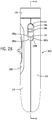
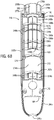
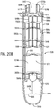
- FIG. 1 illustrates an isometric view of an oral irrigator including a handle with each of a pause valve assembly and a swivel assembly.
- Figs. 2A and 2B are elevation views of the handle of Fig. 1 .
- the oral irrigator 10 may include a handle 100, a reservoir 12, a base 14, and a hose 108, all of which may be interconnected together.
- the base 14 may include a pump 16 fluidically connected to the reservoir 12 that pumps fluid from the reservoir 12 to a tip 104.
- a control 18 is coupled to the base 14 and configured to vary a flow rate or a fluid pressure produced by the pump 16, and/or may activate a particular mode, e.g., a cleaning mode, produced by the pump 16.
- the base 14 and pump 16 may be similar to the base and pump illustrated in U.S. Publication No. 2015/0004559 entitled "Oral Irrigator with Integrated Lid and Base," filed on March 13, 2014.
- the handle may enclose the pump and other components and connect directly to the reservoir.
- the handle may form a main housing for the device.
- the handle 100 is fluidically connected to the pump 16 and a fluid source, such as the reservoir 12, by the hose 108.
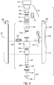
- the handle 100 may generally include a housing 102, a handle collar 118, a tip 104, a tip eject mechanism 141, a backflow valve body 124, a pause valve assembly 142, and a swivel assembly 143, each of which are discussed in turn below.
- the hose 108 fluidically connects the handle 100 to the reservoir 12.
- the hose 108 may be omitted or may be varied as the reservoir 12 may be directly connected to the handles as shown in U.S. Publication No. 2008/0008979 , entitled “Oral Irrigator,” filed on July 7, 2006.
- the handle 100 is also fluidically connected to a removable tip 104, which is configured to be inserted into a user's mouth and to expel fluid against a user's teeth, gums, tongue, etc.
- the tip 104 may be inserted into the handle 100 through a handle collar 118.
- a tip eject button 110 can selectively release the tip 104 from the handle 100. Liquid from the fluid source can be expelled through a tip outlet 105 in the tip 104 when the tip 104 is connected to the handle 100.
- the tip outlet 105 portion of the tip 104 may be shaped as a nozzle or may include a nozzle or other attachment connected thereto.
- the handle 100 may include a pause actuator 112.
- the pause actuator 112 can selectively interrupt the flow of liquid from the fluid source to the tip 104.
- the handle housing 102 may be an integrated component or, as shown in Figs. 2A-5A , may include a first shell 114 and a second shell 116 coupled together (e.g., through ultrasonic welding, fasteners, adhesive, or the like). Each of the first and second shells 114, 116 may be constructed of a rigid material that resists deformation, such as a hard plastic, but it should be noted that various other materials may be used as well. Additionally, the handle housing 102 may include an aesthetically pleasing shape that may conform to a user's hand and may include one or more gripping elements.
- each of the first and second shells 114, 116 may be comprised of a neck 180a, 180b and shell body 192a, 192b.
- the first shell 114 may include first, second, third, fourth, seventh, eighth, and ninth ledges 150a, 152a, 154a, 156a, 162a, 164a, and 166, respectively, for aligning, receiving, retaining, and/or supporting the tip eject mechanism 141, valve assembly 142, swivel assembly 143, hose 108, or other components of the handle 100 within the handle cavity 172 (see Figs. 5A and 5B ).
- the ledges 150a, 152a, 154a, 156a, 162a, 164a, and 166 generally extend in a horizontal plane with respect to a longitudinal axis of the handle 100, and radially inwardly from an interior wall 174a of the first shell 114 within the handle cavity 172.
- the second shell 116 may include first, second, third, fourth, fifth, sixth, seventh, eighth, and tenth ledges 150b, 152b, 154b, 156b, 158, 160, 162b, 164b, and 168, respectively, for aligning, receiving, retaining, and/or supporting the tip eject mechanism 141, valve assembly 142, swivel assembly 143, hose 108, or other components of the handle 100 within the handle cavity 172 (see Figs. 4 , 5A , and 5B ).
- the ledges 150b, 152b, 154b, 156b, 158, 160, 162b, 164b, and 168 of the second shell 116 generally extend in a horizontal plane with respect to the longitudinal axis of the handle 100, and radially inwardly from an interior wall 174b of the second shell 116 within the handle cavity 172.
- Some ledges 150a, 152a, 154a, 156a, 162a, 164a of the first shell 114 may align with a mating ledge 150b, 152b, 154b, 156b, 162b, 164b, respectively, of the second shell 116 when the handle 100 is assembled.
- the depth of the ledges 150a, 150b, 152a, 152b, 154a, 154b, 156a, 156b, 158, 160, 162a, 162b, 164a, 164b, 166, and 168 may be the same or different, and the depth of a given shelf may vary along the width (the lateral dimension) of that shelf.
- Some of the ledges 150a, 150b, 152a, 152b, 154b, 156b, 158, 160, 162a, 162b, 164a, 164b, and 166 may be shaped as arcs.
- mating ledges 150a, 150b, 152a, 152b, 162a, 162b, 164a, 164b may align to form generally circular apertures for receiving portions of components such as the pause valve assembly 142.
- the bodies 192a, 192b of the first and second shells 114, 116 may also include a plurality of vertical support walls 148a, 148b for supporting the ledges 150a, 150b, 152a, 152b, 154a, 154b, 156a, 156b, 158, 160, 162a, 162b, 164a, 164b, 166, and 168.
- the vertical support walls 148a, 148b may also help to align, receive, retain, and/or support the tip eject mechanism 141, the valve assembly 142, the swivel assembly 143, the hose 108, or other components of the handle 100 within the handle cavity 172.
- the vertical support walls 148a, 148b may be as deep as the ledges 150a, 150b, 152a, 152b, 154a, 154b, 156a, 156b, 158, 160, 162a, 162b, 164a, 164b, 166, and 168 they abut, or may be less deep.
- one or more pegs 169 may extend from the interior wall 174 of one of the shells 114, 116 (e.g., in the depicted embodiment, the first shell 114) proximate the first and ninth ledges 152a, 166, respectively, and between the fourth and seventh ledges 156a, 162a, respectively, adjacent a vertical support wall 148a.
- Each peg 169 may extend into the handle cavity 172 beyond a plane defined by a circumferential edge of the exterior wall 184b of the second shell 116.
- Each peg 169 may be adapted to mate with a corresponding boss defining holes 170 proximate the first, sixth, and tenth ledges 150b, 160, and 168, respectively, of the opposing shell 114,116 (e.g., in the depicted embodiment, the second shell 116).
- the pegs 169 and the holes 170 may be dimensioned such that each peg 169 will relatively snugly fit within its corresponding hole 170. The friction resulting from this fit may resist decoupling of the shells 114, 116.
- the first and second shells 114, 116 may be joined using glue, epoxy, fasteners, sonic welding, any other known method for joining two items, or by a combination of known methods.
- the outer surface of the exterior walls 184a, 184b of the first and second shells 114, 116 may each define a C-shaped depression 186a, 186b with respective upper surfaces 188a, 188b and lower surfaces 190a, 190b.
- opposing depressions 186a, 186b define a pocket 186 surrounding an opening 194.
- the first shell 114 may also include a pause actuator aperture 204 for receiving a pause actuator 112 and a recessed pause actuator frame 390.
- the pause actuator aperture 204 may have an upper portion 392 and a lower portion 394.
- both the pause actuator aperture 204 and the pause actuator frame 390 are oval-shaped, but may be any shape.
- the body 192a, 192b of each of the first and second shell 114, 116 may terminate in a semicircular hose cut-out 144a, 144b.
- the cut-outs 144a, 144b together define a substantially circular aperture 146 through which the hose 108 passes.
- the neck 180a, 180b of each of the first and second shell 114, 116 includes an interior wall 176a, 176b and an exterior wall 178a, 178b.
- the interior and exterior walls 176a, 176b, 178a, 178b may be generally semicylindrical in shape such that when the first and second shells 114, 116 are assembled to form the housing 102, the interior and exterior walls 176a, 176b, 178a, 178b form generally concentric cylinders with an annular recess 177a, 177b defined therebetween for receiving a spring 216.
- the exterior walls 178a, 178b may be continuous or may have one or more interruptions or gaps 206 near the midpoint of the width of each of the first and second shell 114, 116.
- the exterior walls 178a, 178b may include a lip 208a, 208b and the interior walls 176a, 176b may extend beyond the plane of the lips 208a, 208b.
- the interior walls 176a, 176b define a cylindrical tip cavity 182 configured to receive a tip 104.
- the handle 100 may include a generally circular handle collar 118.
- the interior surface may be ribbed and may define a tip-receiving aperture 210 for receiving the tip 104.
- the diameter of the internal surface may be same as the internal diameter of the interior walls of the neck 180a, 180b.
- the spring 216 may be positioned in or under the handle collar 118, such as by being inserted into an annular well 218 defined in the handle collar 118 or molded into the handle collar 118 (see Fig. 4 ).
- the tip eject mechanism 141 aids in the insertion and removal of a tip 104.
- the tip eject mechanism 141 is substantially similar to the tip eject mechanism described in U.S. Patent Application No. 14/555,339 .
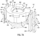
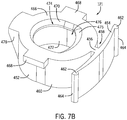
- the tip eject mechanism 141 or tip release assembly comprises a cylindrical valve cap 122, a latch 121, and a tip eject button 110.
- the tip eject button 110 is configured to mechanically initiate the release of a tip 104 from the handle 100, such as by sliding the button 110 upward toward the tip outlet 105.
- the tip eject button 110 may be formed with an exterior slider portion 196 and an interior slider portion 200 that are separated from each other by a neck 202.
- the exterior slider portion 196 may be substantially obround in shape and may include a tab grip 198, which may help a user's fingers or hand to more easily operate the tip eject button 110 and prevent the user's finger or hand from slipping off the tip eject button 110.
- An upper end of the interior slider portion 200 may include a nose 201 that projects radially inward therefrom.
- the exterior slider portion 196 may be approximately the same length as the interior slider portion 200, as in the embodiment depicted in Figs. 7A and 7B , or may be shorter than or longer than the interior slider portion 200.
- the lateral and longitudinal dimensions of the neck 202 are smaller than the related dimensions of the exterior and interior slider portions 196, 200 such that a circumferential channel is formed between the exterior and interior slider portions 196, 200 about the neck 202.
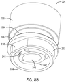
- the valve cap 122 may receive at least a portion of a tip 104 and help provide a secure connection between the tip and the handle 100.
- the valve cap 122 may include a body 226 having an upper end 223 and a lower end 224, and a circumferential rim 220 near the lower end 224.
- the interior of the valve cap 122 may define a tip cavity 222 for receiving a tip 104.
- the latch 121 is configured to releasably engage a tip 104 to both secure it to the handle 100 and aid in removing the tip 104 from the handle 100.
- the latch 121 may comprise a latch body 452 to which spring legs 454 are attached via a neck 456.
- the spring legs 454 extend laterally apart from each other on opposing sides of the neck 456 along a side of the latch body 452 opposite the tip eject button 110.
- the neck 456 separates the spring legs 454 from the latch body 452 such that a gap 458 is formed between each of the spring legs 454 and the latch body 452.
- each spring leg 454 may terminate in a foot 462.
- the outer surface of each foot 462 may have a bulbous projection 464 outward along the width.
- Each spring leg 454 may be flexible, deformable, and/or resilient such that it returns to its original shape and configuration after being compressed.
- a top surface 466 of the latch body 452 comprises ledges 468 that are laterally opposed to each other and which extend radially outward and partially around the perimeter of the latch body 452 on the sides between the spring legs 454 and the tip eject button 110.
- the ledges 468 extend laterally away from the latch body 452 and have a width sufficient to interface with flat surfaces of the housing 100 and thereby prevent rotation of the latch body 452.
- the latch body 452 also comprises an interior lip 470 that extends generally radially inward above an interior wall 472.
- the interior lip 470 may be chamfered, as depicted in Fig. 7A and 7B , or may be smooth and may define a tip-receiving aperture 474 for receiving the tip 104.
- the perimeter defined by the interior lip 470 may be an irregular oval or bell shape, as depicted in Fig. 7A and 7B , or may be any other shape.
- the shape of the perimeter may be complementary to the tip 104 that is received in the tip-receiving aperture 474.
- a locking edge 475 of the interior lip 470 may be positioned adjacent to the spring legs 454. The locking edge 475 may extend radially outward beyond the surface of the interior wall 472 in order to engage a corresponding groove formed within a tip 104 and thereby retain the tip 104 within the latch body 452.
- the interior walls 472 of the latch body 452 may define a valve cap cavity 476, which is configured to receive the upper end 223 of the body 226 of the valve cap 122.
- a cross-sectional area of the valve cap cavity 476 may thus be greater than a cross-sectional area of the tip-receiving aperture 474.
- the valve cap cavity 476 may be substantially obround in shape and thus oblong as compared to the circular shape of the body 226 of the valve cap 122.
- the latch body 452 also includes a chamfered wall 478 on the outside sidewall opposite the neck 456 and spring legs 454.
- the chamfered wall 478 may include an opening between two chamfered legs or it may be solid.
- the handle 100 may include a backflow valve body 124 for enclosing or supporting a reed valve (not shown).
- the backflow valve body 124 may include a generally cylindrical top end 230 and a bottom end 232 separated by a generally cylindrical neck 234 and an annular rim 236.
- the external diameter of the top end 230 may be approximately the same as the external diameter of the rim 236, and both diameters may be greater than the external diameter of the bottom end 238, which in turn may be greater than the external diameter of the neck 234.
- a sealing member 120a such as an O-ring, may be received in the neck 234.
- the interior of the backflow valve body 124 may define a valve cavity 246 having an upper portion 248 and a lower portion 249.
- a sealing member 120b such as a U-cup, may be received in an upper portion 248 of the valve cavity 246 above and adjacent to a ledge 250 positioned about midway along the height of the top end 230 of the backflow valve body 124.
- the bottom end 232 of the backflow valve body 124 includes a bottom edge 238 that includes a keyed feature 240.
- the bottom edge 238 also includes a flap support 242 for supporting or securing an optional reed valve (not shown).
- the flap support 242 may be formed as a generally circular ring having a diameter narrower than the upper portion 248 of the valve cavity 246 and may be connected to the bottom edge 238 via a bridge 244.
- the flap support 242 may be angled such that only a portion, for example the portion adjacent to the bridge 244, is in the same plane as the bottom edge 238 of the bottom end 232 of the backflow valve body 124 and the remainder of the flap support 242 is angled inward and upward toward the valve cavity 246 such that it does not reach the plane of the bottom edge 238.
- the pause valve assembly 142 allows a user to interrupt fluid flow to the tip 104 without removing his or her hand from the handle 100 and without turning off power to the oral irrigator 10.
- the pause valve assembly 142 may include an upper valve body 126, a lower valve body 128, a shuttle valve 134 received within the upper and lower valve bodies 126, 128, a shuttle retainer 130 and a poppet assembly 136 both received within the lower valve body 128, and a pause actuator 112 operably connected to the shuttle valve 134 by a retaining ring 132 such that selective movement of the actuator 112 also moves the shuttle valve 134 within the upper and lower valve bodies 126, 128.
- the various components of the pause valve assembly 142 will now be discussed in more detail.
- the upper valve body 126 fluidically connects the chamber 124 and the lower valve body 128.
- the upper valve body 126 may include a head 256 and a base 258 connected by a neck 260.
- Each of the head 256, base 258, and neck 260 may be generally cylindrical and define a valve cavity 262 therethrough.
- the head 256 may include an upper portion 264 and a lower portion 266, and the lower portion 266 may define a chord segment 268 that interrupts the outer cylindrical surface of the lower portion 266.
- the external diameter of the upper portion 264 may be slightly greater than the external diameter of the lower portion 266.
- the external diameters of the both the upper and lower portions 264, 266 of the head 256 may be generally greater than the external diameter of the base 258, which in turn may be greater than the external diameter of the neck 260.
- One or more, such as two, arms 270 may extend laterally from the head 256 near the interface between the head upper and lower portions 264, 266.
- the arms 270 are positioned to engage and act as a track for the pause actuator 112 to move along.
- two arms 270 may be positioned approximately 180 degrees apart from each other on the head 256.
- the arms 270 may be obround in cross-sectional shape as shown in Fig. 11A or may be other shapes.
- the portion of the valve cavity 262 adjacent to the lower portion 266 of the head 256 may include a floor 272 and a shelf 274.
- a flow aperture 276 may be defined in the floor 272 and the flow aperture 276 may have a diameter less than the diameter of any of the head 256, neck 260, and base 258.
- the shelf 274 may include a keyed feature 278 positioned corresponding to the chord segment 268 of the lower portion 266 of the head 256.
- a shelf wall 280 may extend below a bottom surface 282 of the floor 272 of the head 256 near the interface between the base 258 and neck 260 to define a narrowed diameter portion of the valve cavity 262.
- a sealing member 120c such as U-cup, may be positioned on the shelf wall 280.
- a lower valve body 128 operably connects the upper valve body 126 and the valve base 138.
- the lower valve body 128 may include two or more arms 400 connecting an upper plate 402 and a lower plate 404, a lip 406 defined on top of the upper plate 402, and a skirt 408 positioned below the lower plate 404.
- two cuboidal arms 400 are present and they are positioned opposite from each other across each of the upper and lower plates 402, 404.
- Each of the lip 406, upper plate 402, and lower plate 406 may be ring-shaped such that they define respective circular openings 410.
- the skirt 408 may be cylindrical in shape with a skirt cavity 412 defined therethrough.
- the skirt 408 may include an outer skirt wall 414 and an inner skirt wall 416.
- the inner skirt wall 416 may define the skirt cavity 412 and may include one or more tracks 418 formed as grooves or threading.
- a track 418 may extend approximately 360° around the interior skirt wall 416 in an uneven plane such that the ends of the track 418 do not meet but rather are offset from each other along a longitudinal axis of the handle 100.
- the external diameter of the upper plate 402 may be approximately equal to the external diameter of the lower plate 404, and both diameters may be greater than the external diameter of the lip 406 but less than the external diameter of the skirt 408.
- a sealing member 120d such as a U-cup, may be positioned within the skirt 408 under the lower plate 404
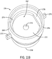
- a shuttle retainer 130 receives fluid flowing past the poppet assembly 136 when the handle 100 is in pause mode.
- the shuttle retainer 130 may be generally cylindrical with an open first end 290 and open second end 292.
- the shuttle retainer 130 may include an exterior wall 294 and a stepped interior wall 296 defining a cavity 298 that extends between the open first and second ends 290, 292.
- the open first end 290 may include a top surface 300 having a plurality of tabs 302 separated by notches around the perimeter 304 of the opening 306.
- the tabs 302 may define a broken circular edge with a circumference slightly larger than the circumference of the shuttle valve 134.
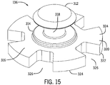
- the shuttle valve 134 interrupts fluid flow through the handle 100 when pause mode is selected.
- the shuttle valve 134 includes a cylindrical body 332 and a frustum-shaped base 334.
- the body 332 may be interrupted by a connector groove 336 positioned about midway along the length of the body 332.
- the external diameter of the base 334 may be greater than the external diameter of the body 332, which may in turn be greater than the external diameter of the connector groove 336.
- the shuttle valve 134 further includes a flow lumen 342 defined within the body 332 and a base cavity 348 defined within the base 334.
- An open first end 338 of the shuttle valve 134 is fluidically connected to an open second end 340 by the flow lumen 342 and the base cavity 348.
- the body 332 of the shuttle valve 134 may include a top surface 344 and the base 334 may include a bottom surface 346.
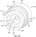
- a poppet assembly 136 is used to selectively disconnect fluid flow from the hose 108 to the valve cap 122.
- the poppet assembly 136 may include a generally circular cap 312 connected to a poppet support plate 316 by a cylindrical poppet neck 318.
- An annular platform 314 may encircle the neck 318 above the poppet support plate 316.
- the diameter of the platform 314 may be approximately equal to the diameter of the cap 312 and less than the widest diameter of the poppet support plate 316.
- the poppet support plate 316 includes a first surface 320, a second surface 322, and a plurality of sprockets 324 extending outwardly from the platform 314. Two adjacent sprockets 324 may be separated from each other to define a flow path 326 therebetween.
- a sealing member 120e may be seated around the poppet neck 318 between the cap 312 and platform 314.
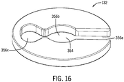
- a retaining ring 132 operably connects the pause actuator 112 to the shuttle valve 134.
- the retaining ring 132 may be disc-shaped and may include a keyhole cutout 354, which may include a plurality of forms.
- the retaining ring may have a first slot 356a, a center aperture 356b, and a hinge aperture 356c.
- the center aperture 356b in the keyhole cutout 354 may be sized to fit around the connector groove 336 of the shuttle valve 134.
- the retaining ring 132 may be a snap ring.
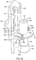
- the pause actuator 112 is moved by a user to place the handle in a pause or an irrigate mode.
- the pause actuator 112 may include an exterior slider plate 362 and an interior slider plate 364.
- the exterior slider plate 362 may include a grip portion 366 for aiding a user in gripping and moving the pause actuator 112.
- the interior slider plate 364 may have a concave shape and may include a concave or rear face 368 from which one or more walls 370 extend. For example, two walls 370 that are generally rectangular cuboids in shape are shown in Fig. 10 .
- An upper shelf 372 and a lower shelf 374 may also extend parallel to each other from the rear face 368.
- a first upper prong 376a and a second upper prong 376b may extend from the upper shelf 372 away from the rear face 368.
- a first lower prong 378a and a second lower prong 378b may similarly extend from the lower shelf 374.
- the first prongs 376a, 378a are laterally spaced from the second prongs 376b, 378b and are connected by a shelf wall 380 that forms a semicircle from the terminus 382a of one prong 376a, 378a to the terminus 382b of the laterally opposed prong 376b, 378b.
- Each upper prong 376a, 376b may be separated from its proximal lower prong 378a, 378b by a retaining gap 384 between the upper and lower shelves 372, 374.
- the prongs 376a, 376b, 378a, 378b may be any shape.
- the swivel assembly 143 may help minimize or prevent translation of rotational movement of the handle 100 or the hose 108 relative to the other.
- the swivel assembly 143 may include a valve base 138 and a bushing 140.
- the valve base 138 is configured to be received within the stationary lower valve body 128.
- the valve base 138 may include an annular protruding rim 424, a cylindrical body 426, and an elongated barbed tip 428.
- the valve base 138 defines a flow cavity 430 from the barbed tip 428 through to the top surface 432 of the rim 424.
- the rim 424 may include one or more threads 434.
- Each thread 434 may extend approximately 360° around the rim 424 in an uneven plane such that the ends of the thread 434 do not meet but rather are offset from each other along a longitudinal axis of the handle 100.
- the threads 434 which may be complimentary to the tracks 418 of the inner skirt wall 416 of the skirt 408 of the lower valve body 128, may help to align or assemble the valve base 138 and lower valve body 128.
- the barbed tip 428 may include one or more gripping components 436 that enhance the connection between the valve base 138 and the hose 108.
- the swivel assembly 143 may also include a cylindrical bushing 140 defining a barb aperture 442 configured to receive the barbed tip 428 of the valve base 138.
- the bushing 140 may include a rim 444 and a body 446.
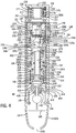
- Figs. 3-5B and 7A-17 may be assembled within the housing 102 as follows.
- the upper end 223 of the body 226 of the valve cap 122 may be received in the valve cap cavity 476 of the latch 121.
- the perimeter of the interior lip 470 may directly align with or may be slightly offset from the tip cavity 222 of the valve cap 122.
- the upper end 223 of the body 226 of the valve cap 122 may not completely fill the volume of the valve cap cavity 122 such that lateral movement of the latch 121 toward or away from the tip eject button 110 is permitted.
- the nose 201 of the interior slider portion 200 of the tip eject button 110 may abut and interface with the chamfered wall 478 of the latch 121.
- the top surface 466 of the latch 121 may be below and adjacent to the first ledge 150a, 150b, and the bottom of the latch body 452 may be adjacent to or rest upon the second ledge 152a, 152b.
- the exterior slider portion 196 of the tip eject button 110 When the housing is assembled, the exterior slider portion 196 of the tip eject button 110 may be positioned within the pocket 186 of the housing 102, the neck 202 may be received within the opening 194 within the pocket 186, and the interior slider portion 200 may be positioned against an interior wall 174 of the housing 102 opposite from the pocket 186.
- the upper surface 188 and lower surface 190 of the pocket 186 may extend beyond the length of the tip eject button 110 such that the pocket 186 is longer than the exterior and interior slider portions 196, 200 and the neck 202 is shorter than a longitudinal dimension of the opening 194 in the pocket 186.
- the tip eject button 110 is both retained within the opening 194 in the pocket 186 and can slide longitudinally within the pocket 186 as the exterior and interior slider portions 196, 200 travel on either side of the upper and lower surfaces 188, 190 of the pocket 186.
- the lip 406 of the lower valve body 128 may be received in the base 258 of the upper valve body 126 and may be positioned below and adjacent to the sealing member 120c positioned under the shelf wall 280 of the valve cavity 262.
- the shuttle retainer 130 may be received in the skirt cavity 412 of the lower valve body 128.
- the exterior wall 294 of the shuttle retainer 130 may be positioned adjacent to the inner skirt wall 416 of the lower valve body 128.
- the second end 292 of the shuttle retainer 130 may be positioned adjacent to the first surface 320 of the poppet support plate 316.
- the top surface 300 of the shuttle retainer 130 may be positioned below and adjacent to the sealing member 120d positioned under the lower plate 404 of the lower valve body 128.
- tabs 302 and notches in the top surface 300 of the shuttle retainer 130 may permit water to reach the sealing member 120d and press the sealing member 120d against the shuttle valve 134 and the lower plate 404 more uniformly, thereby creating a faster or stronger seal than in the absence of water.
- the base 334 and a lower portion of the body 332 of the shuttle valve 134 may be received in the cavity 298 of the shuttle retainer 130.
- the first end 338 of the shuttle valve 134 may be received in the valve cavity 262 of the upper valve body 126.
- the arms 400 of the upper valve body 126 may flank a portion of the body 332 of the shuttle valve 134.
- a shuttle compartment 284 may be formed in the space between the bottom surface 282 of the floor 272 of the head 256 of the upper valve body 126 and the top surface 344 of the body 332 of the shuttle valve 134 when the handle 100 is in pause mode.
- the retaining ring 132 may be flexed at the hinge aperture 356c to widen the slot 356a and seat the center aperture 356b of the retaining ring 132 within the connector groove 336 of the shuttle valve 134.
- the cap 312 and the sealing member 120e positioned around the poppet neck 318 of the poppet assembly 136 may be received in the base cavity 348 of the shuttle valve 134.
- the first surface 320 of the poppet support plate 316 may be positioned below and adjacent to the bottom surface 346 of the base 334 of the shuttle valve 134 and below and adjacent to the second end 292 of the shuttle retainer 130.
- the interior slider plate 364 of the pause actuator 112 may extend from approximately the head 256 of the upper valve body 126 to the skirt 408 of the valve lower housing.
- the walls 370 on the rear face 368 of the interior slider plate 364 may be positioned adjacent to the head 256 of the upper valve body 126, at least when the pause mode is selected.
- the shelf wall 380 may face the body 332 of the shuttle valve 134.
- the retaining ring 132 may be captured in the gap 384 formed between the upper prongs 376a, 376b, and lower prongs 378a, 378b.
- One pair of upper and lower prongs 376a, 378a may traverse some or all of the slot 356a of the keyhole 354 of the retaining ring 132.
- Another pair of upper and lower prongs 376b, 378b may traverse some or all of the hinge aperture 356c.
- the top surface 432 of the protruding rim 424 of the valve base 138 may be positioned below and adjacent to the second surface 322 of the poppet support plate 316.
- One or more of the threads 434 of the rim 424 may be mated with the one or more complementary tracks 418 on the interior skirt wall 416 of the lower valve body 128.
- the base 258 of the upper valve body 126 When the housing 102 is assembled, the base 258 of the upper valve body 126 is positioned adjacent to and below the fourth ledge 156a, 156b.
- Each arm 270 of the upper valve body 126 may extend perpendicularly to and be positioned between a vertical support wall 148a of the first shell 114 and a vertical support wall 148b of the second shell 116.
- the upper plate 402 of the lower valve body 128 may be positioned above the fifth ledge 158 and the skirt 408 of the lower valve body 128 may be positioned above and adjacent to the seventh ledge 162a,162b.
- the exterior slider plate 362 of the pause actuator 112 may be positioned within the pause actuator aperture 204 in the first shell 114 and the interior slider plate 364 may be positioned against an interior wall 174 of the first shell 114 opposite at least a portion of the pause actuator frame 390.
- the upper and lower portions of the aperture 204 extend beyond the length of the exterior slider plate 362 such that the aperture 204 is longer than the exterior slider plate 362 and shorter than the interior slider plate 364.
- the pause actuator 112 is both retained within the aperture 204 and can slide longitudinally within the aperture 204 as the exterior and interior slider plates 362, 364 travel on either side of the aperture 204 and frame 390.
- the barbed tip 428 of the valve base 138 is received in the barb aperture 442 of the bushing 140.
- Eighth ledges 164a, 164b of the shells 114, 116 may be positioned beneath the rim 444 of the bushing 140.
- An end of the hose 108 may fit over the barbed tip 428.
- the hose 108 may exit the cavity 172 of the assembled housing 102 at the aperture 146.
- the lower end 224 of the valve cap 122 may be received in the upper portion 248 of the valve cavity 246 of the backflow valve body 124.
- the lower end 224 may be positioned above and adjacent to the sealing member 120b seated on the ledge 250 of the top end 230 of the backflow valve body 124.
- the rim 220 of the valve cap 122 may be captured between the underside of the second ledge 152a, 152b of the first and second shells 114, 116 and the top end 230 of the backflow valve body 124.
- the neck 234, rim 236, and bottom end 232 of the backflow valve body 124 may be received in the portion of the valve cavity 262 of the upper valve body 126 adjacent to the head 256.
- the rim 236 of the backflow valve body 124 may be positioned adjacent to the shelf 274 of the upper valve body 126 such that the keyed feature 240 of the bottom edge 238 of the backflow valve body 124 mates with the keyed feature 278 of the shelf 274 of the upper valve body 126.
- the sealing member 120a seated in the neck 234 of the backflow valve body 124 may be positioned in the valve cavity 262 of the head 256 of the upper valve body 126.
- the rim 424 of the valve base 138 is received in the skirt 408 of the lower valve body 128 and is positioned under the poppet support plate 316.
- the handle collar 118 may be positioned over the neck 180a, 180b and may be secured to the handle housing 102 by several arcuate tabs 212 extending radially inward from a sidewall of the handle collar 118 that capture the lip 208a, 208b of the neck 180a, 180b (see Figs. 4 , 5A , and 5B ).
- the arcuate tabs 212 of the handle collar 118 may be separated from the bodies 192a, 192b of the first and second shell 114, 116 by a gap 214, the span of which may be decreased by depressing the handle collar 118 towards the bodies 192a, 192b.
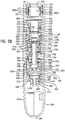
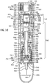
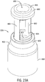
- Figs. 18-27 depict another embodiment of a handle 500.
- similarly numbered features of the components of the handle 500 have similar designs, constructions, function, and operations as those of the components described above unless otherwise noted.
- the exterior of the handle 500 may appear the same as or similar to the handle 100 of Figs. 1 , 2A , and 2B .
- the handle 500 may not include either or both of a backflow valve body 124 and a bushing 140.
- the handle 500 of Figs. 18-27 may include a first shell 514 and a second shell 516, each comprised of a neck 580a, 580b and shell body 592a, 592b (see Figs. 20A and 20B ).
- the first shell 514 may include first, second, third, fourth, seventh, and eighth ledges 550a, 552a, 554a, 556a, 562a, and 564a, respectively, that are constructed similarly to the previously described ledges 150a, 152a, 154a, 156a, 162a, and 164a, respectively, and also have similar functions.
- the second shell 516 may include first, second, third, fourth, fifth, sixth, seventh, eighth, and ninth ledges 550b, 552b, 554b, 556b, 558, 560, 562b, 564b, and 566, respectively, that are constructed similarly to the previously described ledges 150b, 152b, 154b, 156b, 158, 160, 162b, 164b, and 168, respectively, and also have similar functions.
- the bodies 592a, 592b of the first and second shells 514, 516 may also include a plurality of vertical support walls 548a, 548b, pegs 569, and holes 570 similar to the corresponding features of the first-described embodiment.
- the outer surface of the exterior walls 584a, 584b of the first and second shells 514, 516 may each define a C-shaped depression 586a, 586b with respective upper surfaces 588a, 588b and lower surfaces 590a, 590b similar to the corresponding features described above.
- opposing depressions 586a, 586b define a pocket 586 surrounding an opening 594.
- An elongate tip eject button 510 may be formed with an exterior slider portion 596 and an interior slider portion 600 that are separated from each other by a neck 602.
- the exterior slider portion 596 may include a tab grip 598.
- the interior slider portion 600 may include a nose 601 that projects radially inward therefrom.
- the design and construction of the tip eject button 510, and its position relative the first and second shells 514, 516 may be the same as or similar to the tip eject button 110 of the first-described embodiment.
- the first shell 514 of the present embodiment may also include a pause actuator aperture 604 for receiving a pause actuator 512 and a recessed pause actuator frame 790.
- the pause actuator aperture 604 may have an upper portion 792 and a lower portion 794.
- the body 592a, 592b of each of the first and second shell 514, 516 may terminate in a semicircular hose cut-out 544a, 544b.
- the cut-outs 544a, 544b together define a substantially circular aperture 546 through which a hose passes.
- the neck 580a, 580b of each of the first and second shell 514, 516, respectively, includes an interior wall 576a, 576b, an exterior wall 578a, 578b, and an annular recess 577a, 577b substantially as described above.
- the exterior walls 578a, 578b may include a lip 608a, 608b and the interior walls 576a, 576b, when assembled into the handle 500, define a cylindrical tip cavity 582 configured to receive a tip 104.
- the handle 500 may include a handle collar 518 having similar features and functions to the handle collar 118 described above.
- the handle collar 518 may include a tip-receiving aperture 610 for receiving the tip 104, an annular well 618 for receiving a spring 616, and arcuate tabs 612 for securing the collar 518 onto the first and second shells 514, 516 (see Fig. 18 ).
- a tip eject mechanism 541 of the handle 500 may be substantially the same in its design and operation as the tip eject mechanism 141 described above.
- a pause valve assembly 542 of the handle 500 may include an upper valve body 526, a lower valve body 528, a shuttle valve 534, a shuttle retainer 530, a poppet assembly 536, and a pause actuator 512 operably connected to the shuttle valve 534 by a retaining ring 532 substantially the same as the pause valve assembly 142 described above with the following exceptions.
- an upper valve body 526 may be substantially the same as the upper valve body 126 described above.
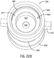
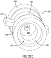
- the portion of the valve cavity 662 adjacent to the head 656 may include a floor 672 and a ledge 686 and a shelf 674 positioned between the floor 672 and ledge 686.
- One or more arms 670 may extend laterally from the head 656 and neck 660.
- the arms 670 may be rectangular cuboids in shape as shown in Figs. 22A-C or may be other shapes.
- the external diameters of the head 656 and base 658 may be approximately equal and both may be greater than the external diameter of the neck 660.
- the head 656 may be shorter, the neck 660 may be longer, and the base 658 may be wider.
- the head 656 may not include separate upper and lower portions 264, 266.
- the head 656 may not include a chord segment 268 and the shelf 674 may not include a keyed feature 278.
- a lower valve body 528 may be substantially the same as the lower valve body 128 described above.
- the lower valve body 528 includes an annular wall 820 positioned between a lower plate 804 and a skirt 808.
- An upper portion 822 of the skirt 808 may angle inward toward the annular wall 820.
- the external diameter of the upper plate 802 may be approximately equal to the external diameter of the annual wall 820, and both diameters may be greater than the external diameter of the lip 806 but less than the external diameter of the skirt 808.
- the lip 806 may be taller, the arms 800 may be elongated, and the skirt 808 may be truncated.
- the inner skirt wall 816 may not include any tracks 418.
- a sealing member 520d such as a U-cup, may be positioned under the lower plate 804 adjacent the annual wall 820.
- the sealing member 520d may be overmolded into the lower plate 804 or the annual wall 820.
- a shuttle retainer 530 may include a cylindrical body 707 and a lip 709 that meet at a ledge 708.
- the shuttle retainer 530 may include an exterior wall 694 and a stepped interior wall 696 defining a cavity 698 that extends from an open first end 690 to an open second end 692.
- the open first end 690 may include a top surface 700 having a plurality of tabs 702 separated by notches around the perimeter 704 of the opening 706.
- the tabs 702 may define a broken circular edge with a circumference slightly larger than the circumference of the shuttle valve 534.
- the upper portion 710 of the lip may angle inwards towards the tabs 702 and opening 706.
- the shuttle valve 534 may have substantially the same features as the shuttle valve 134 descripted above.
- the body 732 is elongated compared to the body 332 of the shuttle valve 134 depicted in Fig. 14 .
- the poppet assembly 536 may be substantially the same in its design and operation as the poppet assembly 136 described above.
- the cap 712 includes a recessed center portion 713, the poppet neck 718 is elongated compared to poppet neck 318, and the platform 714 is taller and its perimeter sits closer to the flow path 726 than the platform 314.
- a retaining ring 532 may be substantially the same in its design and operation as the retaining ring 132 described above.
- a pause actuator 512 may be substantially the same in its design and operation as the pause actuator 112 described above.
- the interior slider plate 764 may include a lateral tab 765 on each lateral side of the plate 764 adjacent the first and second upper and lower prongs 776a, 776b, 778a, 778b.
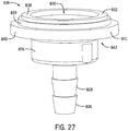
- a swivel assembly 843 may include a valve base 538.
- the swivel assembly 843 may not include a bushing 140.
- the valve base 538 may include a series of stacked, concentric, annular discs instead of an annular protruding rim 424.
- the top disc 838 may have the smallest diameter of the stack with the middle disc 839 having a diameter between the top disc 838 and the bottom disc 840.
- each of the discs 838, 839, 840 may increase between each disc, with the top disc 838 having the smallest thickness, the middle disc 839 having a thickness between the two discs 838, 840, and the bottom disc 840 having the greatest thickness.
- the example of Fig. 27 may not include any threads 434.
- the handle components of Figs. 18-27 may be assembled within the housing 502 similarly to how the handle 100 is assembled, except as described below.
- the assembled components of Figs. 18-27 of handle 500 may occupy a greater portion of the cavity 572 as measured along a longitudinal axis of the handle 500.
- the barbed tip 828 may terminate lower in the cavity 572 than the barbed tip 428 of the first-described handle 100.
- the rim 620 of the valve cap 522 may be captured between the underside of the second ledge 552a, 552b of the first and second shells 514, 516 and the top surface of the head 656 of the upper valve body 526.
- the lower end 624 of the valve cap 522 may be received in the portion of the valve cavity 662 of the upper valve body 526 adjacent the head 656.
- the lower end 624 may be positioned above and adjacent to a sealing member 520b seated on the shelf 674 of the upper valve body 526.
- the arms 670 may extend laterally to a vertical support wall 548a, 548b and be positioned adjacent to and under the third ledges 554a, 554b.
- the exterior wall 694 of the shuttle retainer 530 may be positioned adjacent to the inner skirt wall 816 of the lower valve body 528 such that the stepped profile of the exterior wall 694 follows the stepped profile of the inner skirt wall 816.
- the top surface 700 of the shuttle retainer 530 may be positioned adjacent to the upper portion 822 of the skirt 808 but may not extend to the annular wall 820 and may not extend to the sealing member 520d adjacent the annual wall 820 or lower plate 804.
- a greater portion of the body 732 of the shuttle valve 534 may be received in the cavity 698 of the shuttle retainer 530.
- the shuttle compartment 684 formed in the space between the bottom surface 682 of the floor 672 of the head 656 of the upper valve body 526 and the top surface 744 of the body 732 of the shuttle valve 534 when the handle 500 is in pause mode may be longer than or have a greater volume than the shuttle compartment 284 of the handle 100.
- the walls 770 on the rear face 768 of the interior slider plate 764 of the pause actuator 512 may be positioned approximately level with the neck 660 of the upper valve body 526 when pause mode is selected and may be positioned near or adjacent the head 656 when irrigate mode is selected.
- the top surface 432 of the top disc 838 of the valve base 538 may extend beneath and adjacent to the second surface 722 of the poppet support plate 716.
- the middle disc 839 may be positioned adjacent the inner skirt wall 816.
- the outer diameter of the bottom disc 840 may be approximately the same as the outer diameter of the skirt 808 of the lower valve body 528 such that when the bottom disc 840 is positioned under the skirt 808, the outer skirt wall 814 may be flush with the outer surface 841 of the bottom disc 840.
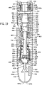
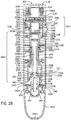
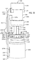
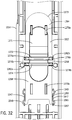
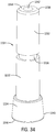
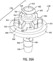
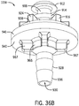
- Figs. 28-36 depict another embodiment of a handle 1000.
- similarly numbered features of the components of the handle 1000 have similar designs, constructions, functions, and operations as those of the components described above unless otherwise noted.
- the exterior of the handle 1000 may appear the same as or similar to the handle 100 of Figs. 1 , 2A , and 2B .
- the poppet assembly may be integrated into the valve base to form an integrated valve base 1138.
- the handle 1000 may include a retaining clip 1130 and not include a shuttle retainer 130, 530.
- the handle 1000 of Figs. 28-36 may include a first shell 1014 and a second shell 1016, each comprised of a neck 1080a, 1080b and shell body 1092a, 1092b (see Figs. 30A and 30B ).
- the first shell 1014 may include first, second, third, fourth, fifth, seventh, and eighth ledges 1050a, 1052a, 1054a, 1056a, 1058a, 1062a, and 1064, respectively, that are constructed similarly to the previously described ledges 150a, 152a, 154a, 156a, 158a, 162a, and 164a and also have similar functions.
- the first shell 1014 may also include one or more lateral brackets 1047 affixed to the interior wall 1074a that may help retain the pause actuator 1012 in the on/irrigate or paused position, as selected.
- Each lateral bracket 1047 may include a plurality of catches or detents 1049 that help to mechanically releasably capture the pause actuator 1012.
- the detents 1049 may be shaped complimentary to a portion of the pause actuator 1012. In the example depicted in Fig. 32 , the detents 1049 may be semicircular in shape.
- the second shell 1016 may include first, second, third, fourth, fifth, sixth, and seventh ledges 1050b, 1052b, 1054b, 1056b, 1058b, 1060, and 1062b, respectively, that are constructed similarly to the previously described ledges 150b, 152b, 154b, 156b, 158, 160, and 162b and also have similar functions.
- the second shell 1016 may also include magnet 1051 and a magnet retainer 1049 for securing the magnet 1051.
- the magnet 1051 may help connect the handle 1000 to the base unit via a corresponding magnet in the base unit as described in U.S. Patent Application No. 15/843,911 entitled "Oral irrigator with magnetic attachment".
- the bodies 1092a, 1092b of the first and second shells 1014, 1016 may also include a plurality of vertical support walls 1048a, 1048b, pegs 1069, and holes 1070 similar to the corresponding features of the first-described embodiment.
- the outer surface of the exterior walls 1084a, 1084b of the first and second shells 1014, 1016 may each define a C-shaped depression 1086a, 1086b with respective upper surfaces 1088a, 1088b and lower surfaces 1090a, 1090b similar to the corresponding features described above.
- opposing depressions 1086a, 1086b define a pocket 1086 surrounding an opening 1094.
- An elongate tip eject button 1010 may be formed with an exterior slider portion 1096 and an interior slider portion 1100 that are separated from each other by a neck 1102.
- the exterior slider portion 1096 may include a tab grip 1098.
- the interior slider portion 1100 may include a nose 1101 that projects radially inward therefrom.
- the design and construction of the tip eject button 1010, and its position relative the first and second shells 1014, 1016 may be the same as or similar to the tip eject button 1010 of the first-described embodiment.
- the body 1092a, 1092b of each of the first and second shell 1014, 1016 may terminate in a semicircular hose cut-out 1044a, 1044b.
- the cut-outs 1044a, 1044b together define a substantially circular aperture through which a hose passes.
- the neck 1080a, 1080b of each of the first and second shells 1014, 1016, respectively, includes an interior wall 1076a, 1076b, an exterior wall 1078a, 1078b, and an annular recess 1077a, 1077b substantially as described above.
- the exterior walls 1078a, 1078b may include a lip 1108a, 1108b and the interior walls 1076a, 1076b, when assembled into the handle 1000, define a cylindrical tip cavity 1082 configured to receive a tip 104.
- the handle 1000 may include a handle collar 1018 having similar features and functions to the handle collar 118 described above.
- the handle collar 1018 may include a tip-receiving aperture 1110 for receiving the tip 104, an annular well 1118 for receiving a spring 1116, and arcuate tabs 1112 for securing the collar 1018 onto the first and second shells 1014, 1016 (see Fig. 28 ).
- a tip eject mechanism 1041 of the handle 1000 may be substantially the same in its design and operation as the tip eject mechanism 141 described above and may include a cylindrical valve cap 1022, a latch 1021, and a tip eject button 1010.
- a pause valve assembly 1042 of the handle 1000 may include an upper valve body 1026, a lower valve body 1028, a shuttle valve 1034, and a pause actuator 112 operably connected to the shuttle valve 534 by a retaining ring 532 substantially the same as the pause valve assembly 142, 542 described above with the following exceptions.
- the pause valve assembly 1042 may include a retaining clip 1130 but not include a shuttle retainer 130.
- the pause valve assembly 1042 may include an integrated valve base 1138 having a poppet assembly 1136 connected to an elongated barbed tip 928.
- an upper valve body 1026 may be substantially the same as the upper valve body 526 described above for handle 500.
- a lower valve body 1028 may be substantially the same as the lower valve body 128 described above.
- the lower valve body 1028 includes an annular wall 1320 positioned between the lower plate 1304 and the skirt 1308.
- the upper portion 1322 of the skirt 1308 may angle inwards towards the annular wall 1320.
- the external diameter of the upper plate 1302 may be approximately equal to the external diameter of the lower plate 1304, and both diameters may be greater than the external diameter of the lip 1306 but less than the external diameter of the annular wall 1320 and the skirt 1308.
- the arms 1300 may be elongated, and the lower valve body 1028 may include an annular wall 1320 and an angled upper portion 1322 of the skirt 1308 may be truncated.
- a sealing member 1020d such as a U-cup, may be positioned under the lower plate 1304 adjacent the annual wall 1320.
- the sealing member 1020d may be overmolded into the lower plate 1304 or the annual wall 1320.
- a pause actuator 1012 may be substantially the same in its design and operation as the pause actuators 112, 512 described above.
- the interior slider plate 1264 may include a lateral tab 1265 on each lateral side of the plate 1264 adjacent the first and second upper and lower prongs 1276a, 1276b, 1278a, 1278b similar to the example depicted in Fig. 21 .
- Each lateral side of a lower end 1263 of the interior slider plate 1264 may terminate in a foot 1267 that may help the pause actuator 1012 be retained in the on/irrigate or paused position, as selected.
- Each foot 1267 may be received in a complimentarily shaped detent 1049 of the lateral bracket 1047 affixed to the interior wall 174a of the first shell 1014.
- Each foot 1267 may include a sloped upper surface 1269 that helps the foot 1267 slide smoothly between detents 1049 as the pause actuator 1012 is moved between the irrigate and pause positions.
- the interior slider plate 1264 may have a generally concave shape and may include a rear face 1268 that is contoured or molded to form an internal face 1271 of the exterior slider plate 1262.
- One or more walls 1270 may extend from the rear face 1268 and may help the pause actuator 1012 maintain a contact with and constant spacing from other components of the pause valve assembly 1042.
- two walls 1270a are shown positioned toward an upper end 1273 of the interior slider plate 1264 are two walls 1270b are shown positioned toward a lower end 1263.
- the upper walls 1270a may interface with the upper valve body 1026 and the lower walls 1270b may interface with the lower valve body 1028.
- a retaining ring 1032 may be substantially the same in its design and operation as the retaining ring 132 described above.
- the shuttle valve 1034 may have substantially the same features as the shuttle valve 134 descripted above.
- the body 1232 is elongated compared to the body 332 of the shuttle valve 134 depicted in Fig. 14 .
- the pause valve assembly 1042 may include a retaining clip 1130 and not include a shuttle retainer 130, 530. Compared to a shuttle retainer 130, 530 the retaining clip 1130 may permit a reduction in the size, including the diameter, of the lower valve body 1028 in which the clip 1130 is received.
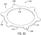
- the retaining clip 1130 may be annular in shape with an interior wall 1196 that defines an aperture and an exterior wall 1194 from which a plurality of spokes 1198 extend radially.
- the retaining clip 1130 is a star washer. The retaining clip 1130 frictionally engages the inner wall of the lower valve body 1028 and retains the sealing member 1120d in place within the shuttle valve 1034.
- the retaining clip 1130 may be received in the skirt cavity 1312 of the lower valve body 1028 such that the spokes 1198 of the clip 1130 are adjacent the inner skirt wall 1316.
- the retaining clip 1130 may be positioned proximate to the annular wall 1320 of the lower valve body 1028 and below the sealing member 1120d positioned under the lower plate 1034 of the lower valve body 1028.
- the inner diameter of the retaining clip 1130 may be slightly larger than the outer diameter of the shuttle valve 1034 to permit the shuttle valve 1034 to travel axially within the aperture of the retaining clip 1130.
- Water may reach the sealing member 1120d through both the inner diameter of the retaining clip 1130 and the fluid flow path 1195 between spokes 1198 and the inner diameter of the annular wall 1320 of the lower valve body 1028 and press the sealing member 1120d against the shuttle valve 1034 and the lower plate 1034 more uniformly, thereby creating a faster or stronger seal against the shuttle valve 1034 than in the absence of water.
- the base 1234 and a lower portion of the body 1232 of the shuttle valve 1034 may be received in the skirt cavity 1312 of the lower valve body 1028 instead of in the cavity 298, 698 of the shuttle retainer 130, 530.
- fluid flows into the handle 1000 during either irrigate mode or pause mode it flows into the skirt cavity 1312 of the lower valve body 1028 instead of the cavity 298, 698 of the shuttle retainer 130, 530.
- the shuttle valve 1034 may be blocked from advancing too far by contact between the top surface 1244 of the shuttle valve 1034 and the bottom surface 1182 of the floor 1172 of the head 1156 of upper valve body 1026.
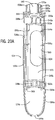
- the poppet assembly is incorporated into the valve base to form an integrated valve base 1138, which may help decrease handle 100 manufacturing costs and/or assembly time by reducing the number of component parts.
- Handles 1000 that include an integrated valve base 1138 have a similar design, construction, function, assembly, and operation as those described above with the following exceptions.
- the integrated valve base 1138 is configured to selectively disconnect fluid flow from the hose 108 to the tip 104.
- the integrated valve base 1138 may include a poppet assembly 1136 connected to an elongated barbed tip 928 by stacked concentric upper and bottom discs 938, 940.
- the poppet assembly 1136 may include a cap 912, including a recessed center portion 913, connected to a poppet support plate 916 by a poppet neck 918.
- An annular platform 914 may encircle the neck 918 above the poppet support plate 916.
- the cap 912 and annular platform 914 are generally sized and shaped to be received in the shuttle valve 1034.
- the poppet support plate 916 includes an upper surface 920 and a plurality of support features 924 extending outwardly from the platform 914.
- a flow path 926 may be defined between two adjacent but spatially separated support features 924.
- a sealing member 1120e may be seated around the poppet neck 918 between the cap 912 and platform 914.
- the upper disc 938 may have a smaller diameter than the bottom disc 940 such that a first surface 937 of the bottom disc 940 is exposed and is available to interface with the skirt 1308 of the lower valve body 1028.
- a reinforced base 966 positioned between the bottom disc 940 and the barbed tip 928 may include a plurality of radially extending arms 967 for stability when seated against the bushing 1040.
- the barb aperture 1342 defined within the bushing 1040 is of larger diameter than the barbed tip 928 of the integrated valve base 1138, allowing the hose to fit thereon.
- the integrated valve base 1138 defines a flow cavity 930 from the barbed tip 928 through to the top surface 932 of the upper disc 938.
- the barbed tip 928 may include one or more gripping components 936 that enhance the connection between the integrated valve base 1138 and the hose 108.
- fluid can flow from the hose 108 through the flow cavity 930 in the integrated valve base 1138, through the flow path 926 between support features 924 of the poppet support plate 916, into the skirt cavity 1312 of the lower valve body 1028, into the base cavity 1248 of the shuttle valve 1034, and into the flow lumen 1242 of the shuttle valve 1034.
- the handle components of Figs. 28-36 may be assembled within the housing 1002 similarly to how the handle 500 is assembled, except as described below.
- the arms 1170 of the valve cap 1022 may be positioned adjacent to the third ledges 1054a, 1054b rather than under the third ledges 554a, 554b.
- the lip 1180 of upper valve body 1026 may be positioned under the fourth ledge 1056a, 1056b rather than above the fourth ledge 556a, 556b.
- the sealing member 1020c may be positioned under the lip 1180, adjacent to the base 1158 of the upper valve body 1026, and above the lip 1306 of the lower valve body 1028.
- the upper plate 1302 of the lower valve body 1028 may be positioned above and adjacent the fifth ledge 1058a, 1058b.
- the retaining clip 1130 may be positioned proximate to the annular wall 1320 of the lower valve body 1028 and below the sealing member 1120d positioned under the lower plate 1034 of the lower valve body 1028.
- the barbed tip 928 of the integrated valve base 1138 is received in the barb aperture 1342 of the bushing 1040.
- the rim 1344 of the bushing 1040 may be positioned on top of the seventh ledges 1062a, 1062b.
- the walls 1270a on the rear face 1268 of the interior slider plate 1264 of the pause actuator 1012 may be positioned near the interface between the neck 1160 and base 1158 of the upper valve body 1026 when pause mode is selected and may be positioned near or adjacent the head 1156 when irrigate mode is selected.
- the cap 912, poppet neck 918, and annular platform 914 of the poppet assembly 1136 and the sealing member 1120e positioned around the poppet neck 918 may be received in the base cavity 1248 of the shuttle valve 1034.
- the first surface 920 of the poppet support plate 916 may be positioned below and adjacent to the bottom surface 1246 of the base 1234 of the shuttle valve 1034.
- the poppet support plate 916 and upper disc 938 of the integrated valve base 1138 are received in the skirt cavity 1312 of the lower valve body 1028.
- the outer diameter of the bottom disc 940 of the integrated valve base 1138 may be approximately the same as the outer diameter of the skirt 1308 of the lower valve body 1028 such that when the first surface 937 of the bottom disc 940 is positioned under the skirt 1308, the outer skirt wall 1314 may be flush with an outer surface 941 of the bottom disc 940.
- the barbed tip 928 of the integrated valve base 1138 is received in the barb aperture 1342 of the bushing 1040.
- a rim 1344 of the bushing 1040 may rest on the seventh ledges 1062a, 1062b.
- the bushing 1040 may freely rotate on the seventh ledges 1062a, 1062b to allow the integrated valve base 1138 and connected valve assembly to freely rotate or swivel within the handle 100.
- a user may insert a tip 104 into, and eject a tip 104 from, the handle 100 of Figs. 1-17 according to the following procedures. Insertion and ejection of a tip 104 from the handle 500 of Figs. 18-27 and from the handle 1000 of Figs. 28-36 follows a similar procedure. The procedures are substantially the same as those described in U.S. Patent Application No. 14/555,339 .
- a tip 104 is inserted into the handle 100 by passing an end of the tip 104 opposite the tip outlet 105 through the tip-receiving aperture 210 of the handle collar 118, through the tip receiving cavity 182 defined by the interior walls 174a, 174b of the first and second shells 114, 116, and into the tip-receiving aperture 474 of the latch body 452.
- the tip-receiving aperture 474 of the latch body 452 is partially offset from the tip cavity 222 of the valve cap 122, which is positioned below the tip-receiving aperture 474.
- the tip 104 engages the latch body 452 and pushes the interior lip 470 of the latch body 452 laterally in the direction of the spring legs 454 until the tip-receiving aperture 474 of the latch body 452 and the tip cavity 222 of the valve cap 122 vertically align.
- the spring legs 454 are compressed, and the feet 462 are positioned adjacent to the interior wall 174a, 174b of the first and second shells 114, 116.
- the inserted end of the tip 104 can then proceed through the tip cavity 222 of the valve cap 122, past the sealing member 120b, and into the valve cavity 246 of the backflow valve body 124 or the valve cavity 662 of the upper valve body 526.
- a tip collar 106 on the tip 104 may be biased against the handle collar 118 when the tip 104 is fully inserted into the handle 100.
- the outer diameter of the inserted end of the tip 104 is slightly larger than the inner diameter of the sealing member 120b, thereby creating a fluid-tight seal between the sealing member 120b and the tip 104.
- the D-shape of the perimeter of the interior lip 470 of the latch body 452 which may be complimentary or keyed to the D-shape of the inserted end of the tip 104, help to align the tip 104 in the handle 100.
- the tip 104 may be coupled to the latch 121 by capturing the interior lip 470 of the latch body 452 within an annular recess (not shown) of the tip 104.
- the handle collar 118 of the handle 100 is depressed toward the bodies 192a, 192b of the first and second shells 114, 116 when the tip 104 is coupled with the latch 121.
- the arcuate tabs 212 of the handle collar 118 move along the necks 180a, 180b of the first and second shells 114, 116 toward the bodies 192a, 192b, which decreases the height of the gap 214, and the spring 216 is compressed.
- the compressed spring 216 exerts an upward force, which will return the handle collar 118 back to its original position (i.e., separated from the bodies 192a, 192b by a gap 214) in the absence of another force opposing this upward force.
- this upward force will be opposed by a flange (not shown) on the tip 104 that holds the handle collar 118 down, thereby maintaining the handle collar 118 in a position adjacent to the handle housing 102.
- An audible click or other similar noise may occur when the latch 121 captures the annular recess of the tip 104, thereby providing an audible indication that the tip 104 is attached to the handle 100.
- the noise may be mechanically produced (for example, a click resulting from a portion of the tip 104 impacting a portion of the handle 100, or a click resulting from a portion of the tip 104 springing outward or mechanically deforming).
- a user slides the exterior slider portion 196 of the tip eject button 110 upward toward the handle collar 118 of the handle 100, and maintains the exterior slider portion 196 in that position while inserting a tip 104 into the handle 100 as described above.
- Sliding the exterior slider portion 196 upward along the longitudinal axis of the handle housing also slides the interior slider portion 200 upwards via the connection between the exterior and interior slider portions 196, 200 at the neck 202.
- the nose 201 of the interior slider portion 200 slides upward along the chamfered wall 478 of the latch body 452
- the nose 201 forces the latch 121 to move laterally in the direction of the spring legs 454.
- the tip-receiving aperture 474 of the latch body 452 is thus aligned over the tip cavity 222 of the valve cap 122 before the tip 104 is inserted.
- the inserted tip 104 can then proceed into the valve cavity 246 of the backflow valve body 124 or the valve cavity 662 of the upper valve body 526 as described above.
- a user ejects a tip 104 by sliding the exterior slider portion 196 of the tip eject button 110 upward toward the handle collar 118.
- the nose 201 of the interior slider portion 200 slides upward along the chamfered wall 478 of the latch body 452
- the nose 201 forces the latch 121 to move laterally in the direction of the spring legs 454.
- the latch 121 moves substantially normal or perpendicular to the movement of the tip eject button 110.
- the interior lip 470 disengages from the annular recess in the tip 104 and the tip 104 is decoupled.
- the spring force of the spring 216 on the handle collar 118 helps to eject the tip 104 by forcing the handle collar 118 upward against the flange of the tip 104.
- the force opposing the upward force exerted by the spring 216 is removed, thereby allowing the spring 216 to move the handle collar 118 back to its original position.
- This movement of the handle collar 118 from a position adjacent to the bodies 192a, 192b to its original position provides a visual indication that the tip 104 has been decoupled from the latch 121.
- a user may use the handle 100 of Figs. 1-17 , the handle 500 of Figs. 18-27 , or the handle 1000 of Figs. 28-36 and the oral irrigator to which it is fluidically connected for oral irrigation and/or cleaning of the teeth, gums, and tongue according to the following procedure.
- a tip 104 is connected to the handle 100 as described above, and the handle 100 is fluidically connected to a fluid source, such as a reservoir of an oral irrigator, and power is supplied to the oral irrigator, the handle 100 is ready to use. Fluid flows through the hose 108 into the flow cavity 430 in the valve base 138 and into the cavity 298 of the shuttle retainer 130.
- a fluid source such as a reservoir of an oral irrigator
- irrigate mode fluid flows to the tip 104 as described above when the pause valve assembly 142 is placed in an open position as follows (see Fig. 5B ).
- the shuttle valve 134 which is operably connected to the pause actuator 112 via the retaining ring 132, is moved into the shuttle compartment 284 of the upper valve body 126.
- the top surface 344 of the body 332 of the shuttle valve 134 approaches or contacts the bottom surface 282 of the floor 272 of the head 256 of upper valve body 126.
- a flow gap 350 is simultaneously created between the bottom surface 346 of the base 334 of the shuttle valve 134 and the first surface 320 of the poppet support plate 316 of the poppet assembly 136.
- the cap 312, poppet neck 318, and sealing member 120e of the poppet assembly 136 are positioned below, not seated inside, the base cavity 348 of the shuttle valve 134.
- Fluid can flow from the hose 108 through the flow cavity 430 in the valve base 138, through the flow path 326 between the sprockets 324 of the poppet support plate 316, into the cavity 298 of the shuttle retainer 130, into the base cavity 348 of the shuttle valve 134, and into the flow lumen 342 of the shuttle valve 134.
- the pause valve assembly 142 To initiate pause mode without turning off power to the oral irrigator to which the handle 100 is connected, the pause valve assembly 142 must be moved to a closed position as follows (see Figs. 4 and 5A ). A user manually slides the pause actuator 112 downward relative to the housing 102, such as by grasping the grip portion 366 and moving it away from the handle collar 118 (i.e., in the down or off position) and substantially along a longitudinal axis of the housing 102. This translational movement of the pause actuator 112 also slides the coupled retaining ring 132 downward, which in turn slides the operably connected shuttle valve 134 downward.
- the base 334 of the shuttle valve 134 contacts and seals against the first surface 320 of the poppet support plate 316 such that the cap 312, poppet neck 318, and sealing member 120e are received inside the base cavity 348 of the shuttle valve 134.
- the sealing member 120e helps provide a seal with the base cavity 348 and fluid is partially or completely prevented from entering the base cavity 348. Fluid can flow from the hose 108 through the valve base 138 through the flow path 326 of the poppet support plate 316 and into the cavity 298 of the shuttle retainer 130. But fluid cannot pass into the flow lumen 342 of the shuttle valve 134. Fluid flow is thereby paused or stopped through the shuttle valve 134 to the tip 104.
- the pause mode is implemented by mechanical, not electrical, operation of the pause actuator 112.
- a mechanically actuated pause mode avoids the need for electrical circuitry in the handle 100, which thereby helps improve the safety of the handle 100 and the oral irrigator to which the handle is fluidically connected because electrical circuits are not in close physical proximity to fluid conduits.
- a mechanically-controlled instead of an electrically-controlled pause mode also decreases the manufacturing cost of the handle 100 and the oral irrigator. No separate battery is required in the handle 100 to power such circuits. Alternatively, the handle 100 need not be electrically wired to the oral irrigator. Thus, an easily accessible and selectable pause mode is provided to the user with significantly less manufacturing cost and greater safety.
- the hose 108 can rotate freely relative to the handle 100 to remain free from tangles, bends, or kinks while maintaining a desired handle 100 orientation.
- the hose 108 can rotate at its connection to the handle 100 as components of the handle 100 rotate within and relative to the housing 102.
- valve base 138 may be ultrasonically welded to the skirt 408 of the lower valve body 128 such that rotation of the hose 108 attached to the barbed tip 428 of the valve base 138 rotates the valve base 138, poppet assembly 136, shuttle valve 134, retaining ring 132, and lower valve body 128 within and relative to the housing 102.
- the materials of some or all of the bushing 140, valve base 138, shuttle valve 134, retaining ring 132, and lower valve body 128 are selected to be low-friction so as to introduce minimal to no drag.
Landscapes
- Health & Medical Sciences (AREA)
- Public Health (AREA)
- Veterinary Medicine (AREA)
- Life Sciences & Earth Sciences (AREA)
- Animal Behavior & Ethology (AREA)
- General Health & Medical Sciences (AREA)
- Epidemiology (AREA)
- Dentistry (AREA)
- Heart & Thoracic Surgery (AREA)
- Engineering & Computer Science (AREA)
- Biomedical Technology (AREA)
- Hematology (AREA)
- Anesthesiology (AREA)
- Pulmonology (AREA)
- Water Supply & Treatment (AREA)
- Oral & Maxillofacial Surgery (AREA)
- Infusion, Injection, And Reservoir Apparatuses (AREA)
- Brushes (AREA)
- Reciprocating Pumps (AREA)
- Media Introduction/Drainage Providing Device (AREA)
Description
- The present disclosure relates to oral irrigators.
- Oral irrigators, or water flossers, typically are used to clean a user's teeth and gums by discharging a pressurized fluid stream into a user's oral cavity. The fluid impacts the teeth and gums to remove debris. Often, the oral irrigator includes a fluid supply, such as a reservoir, that is fluidically connected by a hose and pump to an oral irrigator tip, often through a handle. Some oral irrigators include actuators to pause fluid flow through the handle without turning off power to the irrigator. But these often include electrical circuitry within the handle and in close proximity to fluid conduits, which creates a safety hazard. Oral irrigators with such electrical actuators are also expensive to manufacture.
- A user of an oral irrigator often rotates either the handle or the tip relative to the handle in order to direct the fluid to a desired location as well as to hold the handle in a comfortable position. However, the hose can become tangled as the user moves the handle to different positions and orientations with respect to the reservoir in a base unit. The tangles can reduce the effective length of the hose and can hinder storage of the handle in the base unit, both of which make the oral irrigator difficult to use.
- Document
DE 31 01 941 A1 shows an oral irrigator handle comprising: - a housing;
- a fluid inlet into the housing;
- a fluid outlet from the housing;
- a shuttle valve positioned between the fluid inlet and the fluid outlet, the shuttle valve having a hollow cylindrical piston with a cone shaped plug end, and
- a pause actuator operably connected to the shuttle valve to move the shuttle valve between open and closed positions.
- The information included in this Background section of the specification, including any references cited herein and any description or discussion thereof, is included for technical reference purposes only and is not to be regarded as subject matter by which the scope of the invention as defined in the claims is to be bound.
- The technology disclosed herein relates to an oral irrigator handle. Fluid flows from a hose through the handle to an attached tip during irrigate mode. The handle includes a pause actuator that engages a flow restrictor to effect a pause mode, which allows a user to interrupt fluid flow to the tip without removing his or her hand from the handle and without turning off power to the oral irrigator. The pause mode is mechanically controlled without electrical components. The handle also includes a swivel assembly fluidically coupled to the hose. The swivel assembly minimizes or prevents translation of rotational movement of the handle and the hose relative to the other.
- In one exemplary embodiment of the handle disclosed herein, the handle includes a housing, a fluid inlet into the housing, a fluid outlet from the housing, and a pause valve assembly positioned between the fluid inlet and the fluid outlet and capable of interrupting fluid flow through the handle. Fluid can flow into the housing through a hose and out of the housing through an attached tip. The pause valve assembly can include a shuttle valve, which is received in a valve housing, and a pause actuator. In one embodiment, the shuttle valve is coupled to the pause actuator by a retaining ring and selective movement of the actuator is translated to the shuttle valve.
- In some embodiments, the shuttle valve can be positioned to restrict the flow of fluid through the pause valve assembly when the pause mode is selected with the pause actuator. The shuttle valve does not block fluid flow through the handle when the irrigate mode is selected with the pause actuator.
- One embodiment includes a handle with a pause switch assembly connected to the handle. The pause switch assembly includes an actuator slidably connected to the handle and movable between a first position and a second position, and a shuttle valve operably connected to the actuator and positioned between the handle inlet and the handle outlet. During operation of the pause switch, movement of the actuator from the first position to the second position slides the shuttle valve from an irrigate position to a paused position and, in the paused position, the shuttle valve prevents fluid entering an inlet of the handle from reaching an outlet of the handle.
- Another embodiment of the present disclosure includes a handle for an irrigating device. The handle includes a housing in fluid communication with a fluid source. The housing may have a housing inlet and a housing outlet, a tip removably connected to the housing and in fluid communication with the housing inlet, and a pause control connected to the housing and configured to selectively interrupt fluid flow from the handle outlet to the handle inlet. The pause control includes a switch movable along a longitudinal axis of the housing between a first position and a second position and a shuttle valve connected to the switch. Movement of the switch from the first position to the second position slides the shuttle valve from an open position to a closed position. In the open position the fluid flows uninterrupted from the handle inlet to the tip and in the closed position the fluid flow is blocked between the handle inlet and the tip.
- In another embodiment of the present disclosure, a handle for an oral irrigator includes a swivel assembly received within the housing and fluidically coupled to the tip, and a hose connected to and fluidically coupled to the swivel assembly. The swivel assembly minimizes or prevents translation of rotational movement of the handle or the hose relative to the other.
- This Summary is provided to introduce a selection of concepts in a simplified form that are further described below in the Detailed Description. This Summary is not intended to identify key features or essential features of the claimed subject matter, nor is it intended to be used to limit the scope of the claimed subject matter. A more extensive presentation of features, details, utilities, and advantages of the present invention, as defined in the claims, is provided in the following written description of various embodiments and illustrated in the accompanying drawings.
The object of the present invention is defined by the appended claims. -
-
Fig. 1 is a front right isometric view of an oral irrigator, including a handle, in pause mode, for an oral irrigator connected to a hose connectable to a base unit. -
Fig. 2A is a front elevation view of the handle ofFig. 1 . -
Fig. 2B is a right elevation view of the handle ofFig. 1 . -
Fig. 3 is an exploded view of the handle ofFig. 1 . -
Fig. 4 is an elevation view in cross section of one embodiment of the handle ofFig. 1 along line 4-4 inFig. 1 . -
Fig. 5A is an elevation view in cross section of the handle ofFig. 1 along line 5-5 inFig. 1 . -
Fig. 5B is an elevation view in cross section of the handle ofFig. 1 along line 5-5 inFig. 1 , in irrigate mode. -
Fig. 6A is a rear isometric view of a first shell of the handle ofFig. 4 . -
Fig. 6B is a front isometric view of a second shell of the handle ofFig. 4 . -
Fig. 7A is a front isometric view of a tip eject mechanism of the handle ofFig. 4 . -
Fig. 7B is a rear top isometric view of a latch of the tip eject mechanism ofFig. 7A . -
Fig. 8A is a front top isometric view of a backflow valve housing of the handle ofFig. 4 . -
Fig. 8B is a rear bottom left isometric view of the backflow valve housing ofFig. 8A . -
Fig. 9A is a right isometric view of a pause valve assembly of the handle ofFig. 4 . -
Fig. 9B is a rear isometric view of the pause valve assembly ofFig. 9A . -
Fig. 10 is a right rear isometric view of a portion of the pause valve assembly ofFig. 9A . -
Fig. 11A is a front left isometric view of an upper valve body of the pause valve assembly ofFig. 9A . -
Fig. 11B is a front top isometric view of the upper valve body ofFig. 11A . -
Fig. 11C is a bottom right isometric view of the upper valve body ofFig. 11A . -
Fig. 12A is front top isometric view of a lower valve body of the pause valve assembly ofFig. 9A . -
Fig. 12B is a front bottom isometric view of a lower valve body of the pause valve assembly ofFig. 9A . -
Fig. 13 is a front top isometric view of a shuttle retainer of the pause valve assembly ofFig. 9A . -
Fig. 14 is a front isometric view of a shuttle valve of the pause valve assembly ofFig. 9A . -
Fig. 15 is a front top isometric view of a poppet assembly of the pause valve assembly ofFig. 9A . -
Fig. 16 is a front top isometric view of a retaining ring of the pause valve assembly ofFig. 9A . -
Fig. 17 is a front isometric view of a valve base of the handle ofFig. 4 . -
Fig. 18 is an elevation view in cross section of another embodiment of a handle. -
Fig. 19 is an elevation view in cross section of the handle ofFig. 18 . -
Fig. 20A is a rear isometric view of a first shell of the handle ofFig. 18 . -
Fig. 20B is a front isometric view of a second shell of the handle ofFig. 18 . -
Fig. 21 is a right rear isometric view of a pause valve assembly of the handle ofFig. 18 . -
Fig. 22A is a front isometric view of an upper valve body of the pause valve assembly ofFig. 21 . -
Fig. 22B is a front top isometric view of the upper valve body ofFig. 22A . -
Fig. 22C is a bottom right isometric view of the upper valve body ofFig. 22A . -
Fig. 23A is front top isometric view of a lower valve body of the pause valve assembly ofFig. 21 . -
Fig. 23B is a front bottom isometric view of a lower valve body of the handle ofFig. 21 . -
Fig. 24 is a front top isometric view of a shuttle retainer of the pause valve assembly ofFig. 21 . -
Fig. 25 is a front isometric view of a shuttle valve of the pause valve assembly ofFig. 21 . -
Fig. 26 is a front top isometric view of a poppet assembly of the pause valve assembly ofFig. 21 . -
Fig. 27 is a front isometric view of a valve base of the handle ofFig. 18 . -
Fig. 28 is a left side elevation view in cross section of another embodiment of a handle. -
Fig. 29 is a front elevation view in cross section of the handle ofFig. 28 . -
Fig. 30A is a rear elevation view of an interior of a first shell of the handle ofFig. 28 . -
Fig. 30B is a front elevation view of an interior of a second shell of the handle ofFig. 28 . -
Fig. 31 is a right rear isometric view of a pause valve assembly of the handle ofFig. 28 . -
Fig. 32 is a rear isometric view of the first shell of the handle ofFig. 28 and a portion of the pause valve assembly ofFig. 31 . -
Fig. 33 is top front isometric view of a lower valve body of the pause valve assembly ofFig. 31 . -
Fig. 34 is an isometric view of a shuttle valve of the pause valve assembly ofFig. 31 . -
Fig. 35 is an isometric view of a retaining clip of the pause valve assembly ofFig. 31 . -
Fig. 36A is front top isometric view of an integrated valve base of the handle ofFig. 28 . -
Fig. 36B is front bottom isometric view of the integrated valve base ofFig. 36A . - An oral irrigator handle through which fluid flow can be interrupted is disclosed herein. In irrigate mode, fluid flows from a hose into valve components within the handle housing, and out a fluidically connected tip. Fluid flow is interrupted in a pause mode by a mechanically controlled flow restriction valve that is safe and convenient for the user. Fluid flow may be controlled by a pause valve assembly. In one exemplary embodiment, manually operating a pause actuator of a pause valve assembly slides a shuttle valve, via a coupled retaining ring, to a position atop a poppet support assembly that blocks fluid flow through the handle.
- An oral irrigator handle having a swivel assembly is also disclosed herein. The swivel assembly is positioned within the handle housing and allows the hose to rotate 360 degrees relative to the handle, such that as a user moves the handle in various directions and/or rotates the handle, the handle can spin with respect to the hose, reducing the chance that the hose will get tangled, bent, or pinched.
- Turning to the figures, an oral irrigator will now be discussed in more detail.
Fig. 1 illustrates an isometric view of an oral irrigator including a handle with each of a pause valve assembly and a swivel assembly.Figs. 2A and2B are elevation views of the handle ofFig. 1 . - With reference to
Fig. 1 , theoral irrigator 10 may include ahandle 100, areservoir 12, abase 14, and ahose 108, all of which may be interconnected together. The base 14 may include apump 16 fluidically connected to thereservoir 12 that pumps fluid from thereservoir 12 to atip 104. Acontrol 18 is coupled to thebase 14 and configured to vary a flow rate or a fluid pressure produced by thepump 16, and/or may activate a particular mode, e.g., a cleaning mode, produced by thepump 16. Thebase 14 and pump 16 may be similar to the base and pump illustrated inU.S. Publication No. 2015/0004559 entitled "Oral Irrigator with Integrated Lid and Base," filed on March 13, 2014. In other embodiments, the handle may enclose the pump and other components and connect directly to the reservoir. In these embodiments, the handle may form a main housing for the device. - With reference to
Figs. 1-2B , thehandle 100 is fluidically connected to thepump 16 and a fluid source, such as thereservoir 12, by thehose 108. Thehandle 100 may generally include ahousing 102, ahandle collar 118, atip 104, atip eject mechanism 141, abackflow valve body 124, apause valve assembly 142, and aswivel assembly 143, each of which are discussed in turn below. - As noted, the
hose 108 fluidically connects thehandle 100 to thereservoir 12. However, in instances where the irrigator is a handheld unit, thehose 108 may be omitted or may be varied as thereservoir 12 may be directly connected to the handles as shown inU.S. Publication No. 2008/0008979 , entitled "Oral Irrigator," filed on July 7, 2006. - The
handle 100 is also fluidically connected to aremovable tip 104, which is configured to be inserted into a user's mouth and to expel fluid against a user's teeth, gums, tongue, etc. Thetip 104 may be inserted into thehandle 100 through ahandle collar 118. Atip eject button 110 can selectively release thetip 104 from thehandle 100. Liquid from the fluid source can be expelled through atip outlet 105 in thetip 104 when thetip 104 is connected to thehandle 100. In some examples, thetip outlet 105 portion of thetip 104 may be shaped as a nozzle or may include a nozzle or other attachment connected thereto. - As described in more detail below, the
handle 100 may include apause actuator 112. Thepause actuator 112 can selectively interrupt the flow of liquid from the fluid source to thetip 104. - With reference to
Figs. 2A-5B , an exemplary embodiment of thehandle housing 102 will now be discussed in more detail. Thehandle housing 102 may be an integrated component or, as shown inFigs. 2A-5A , may include afirst shell 114 and asecond shell 116 coupled together (e.g., through ultrasonic welding, fasteners, adhesive, or the like). Each of the first andsecond shells handle housing 102 may include an aesthetically pleasing shape that may conform to a user's hand and may include one or more gripping elements. - As shown in
Figs. 3-6B , each of the first andsecond shells neck shell body Figs. 6A and6B , thebodies second shells handle cavity 172 in which components of thehandle 100, such as thetip eject mechanism 141, pausevalve assembly 142,swivel assembly 143, and a portion of thehose 108, may reside. Thefirst shell 114 may include first, second, third, fourth, seventh, eighth, andninth ledges tip eject mechanism 141,valve assembly 142,swivel assembly 143,hose 108, or other components of thehandle 100 within the handle cavity 172 (seeFigs. 5A and5B ). Theledges handle 100, and radially inwardly from aninterior wall 174a of thefirst shell 114 within thehandle cavity 172. - The
second shell 116 may include first, second, third, fourth, fifth, sixth, seventh, eighth, andtenth ledges tip eject mechanism 141,valve assembly 142,swivel assembly 143,hose 108, or other components of thehandle 100 within the handle cavity 172 (seeFigs. 4 ,5A , and5B ). As in thefirst shell 114, theledges second shell 116 generally extend in a horizontal plane with respect to the longitudinal axis of thehandle 100, and radially inwardly from aninterior wall 174b of thesecond shell 116 within thehandle cavity 172. - Some
ledges first shell 114 may align with amating ledge second shell 116 when thehandle 100 is assembled. - The depth of the
ledges ledges first shell 114 andsecond shell 116 are assembled to form the housing102,mating ledges pause valve assembly 142. - The
bodies second shells vertical support walls ledges vertical support walls tip eject mechanism 141, thevalve assembly 142, theswivel assembly 143, thehose 108, or other components of thehandle 100 within thehandle cavity 172. Thevertical support walls ledges - With further reference to
Figs. 6A and6B , one ormore pegs 169 may extend from the interior wall 174 of one of theshells 114, 116 (e.g., in the depicted embodiment, the first shell 114) proximate the first andninth ledges seventh ledges vertical support wall 148a. Eachpeg 169 may extend into thehandle cavity 172 beyond a plane defined by a circumferential edge of theexterior wall 184b of thesecond shell 116. Eachpeg 169 may be adapted to mate with a correspondingboss defining holes 170 proximate the first, sixth, andtenth ledges pegs 169 and theholes 170 may be dimensioned such that each peg 169 will relatively snugly fit within itscorresponding hole 170. The friction resulting from this fit may resist decoupling of theshells second shells - As depicted in
Figs. 2B ,4 ,6A , and6B , the outer surface of theexterior walls second shells depression upper surfaces lower surfaces handle housing 102 is assembled, opposingdepressions opening 194. - With reference again to
Fig. 6A , thefirst shell 114 may also include apause actuator aperture 204 for receiving apause actuator 112 and a recessedpause actuator frame 390. Thepause actuator aperture 204 may have an upper portion 392 and a lower portion 394. In the depicted embodiment, both thepause actuator aperture 204 and thepause actuator frame 390 are oval-shaped, but may be any shape. By placing thepause actuator 112 on thehandle 100, the user may more easily change settings or pause the fluid flow while using an oral irrigator that is fluidically connected to thehandle 100. - With reference to
Figs. 4-6B , thebody second shell out second shells housing 102, the cut-outs circular aperture 146 through which thehose 108 passes. - With reference to
Figs. 3-6B , theneck second shell interior wall exterior wall exterior walls second shells housing 102, the interior andexterior walls annular recess spring 216. Theexterior walls gaps 206 near the midpoint of the width of each of the first andsecond shell exterior walls lip interior walls lips second shells interior walls cylindrical tip cavity 182 configured to receive atip 104. - The
handle 100 may include a generallycircular handle collar 118. The interior surface may be ribbed and may define a tip-receivingaperture 210 for receiving thetip 104. The diameter of the internal surface may be same as the internal diameter of the interior walls of theneck spring 216 may be positioned in or under thehandle collar 118, such as by being inserted into anannular well 218 defined in thehandle collar 118 or molded into the handle collar 118 (seeFig. 4 ). - With reference to
Figs. 3-5B ,7A , and7B , thetip eject mechanism 141 of thehandle 100 will now be discussed in more detail. Thetip eject mechanism 141 aids in the insertion and removal of atip 104. Thetip eject mechanism 141 is substantially similar to the tip eject mechanism described inU.S. Patent Application No. 14/555,339 . Thetip eject mechanism 141 or tip release assembly comprises acylindrical valve cap 122, alatch 121, and atip eject button 110. - The
tip eject button 110 is configured to mechanically initiate the release of atip 104 from thehandle 100, such as by sliding thebutton 110 upward toward thetip outlet 105. Thetip eject button 110 may be formed with anexterior slider portion 196 and aninterior slider portion 200 that are separated from each other by aneck 202. Theexterior slider portion 196 may be substantially obround in shape and may include atab grip 198, which may help a user's fingers or hand to more easily operate thetip eject button 110 and prevent the user's finger or hand from slipping off thetip eject button 110. An upper end of theinterior slider portion 200 may include anose 201 that projects radially inward therefrom. Theexterior slider portion 196 may be approximately the same length as theinterior slider portion 200, as in the embodiment depicted inFigs. 7A and7B , or may be shorter than or longer than theinterior slider portion 200. The lateral and longitudinal dimensions of theneck 202 are smaller than the related dimensions of the exterior andinterior slider portions interior slider portions neck 202. - The
valve cap 122 may receive at least a portion of atip 104 and help provide a secure connection between the tip and thehandle 100. Thevalve cap 122 may include abody 226 having anupper end 223 and alower end 224, and acircumferential rim 220 near thelower end 224. The interior of thevalve cap 122 may define atip cavity 222 for receiving atip 104. - The
latch 121 is configured to releasably engage atip 104 to both secure it to thehandle 100 and aid in removing thetip 104 from thehandle 100. Thelatch 121 may comprise alatch body 452 to whichspring legs 454 are attached via aneck 456. Thespring legs 454 extend laterally apart from each other on opposing sides of theneck 456 along a side of thelatch body 452 opposite thetip eject button 110. Theneck 456 separates thespring legs 454 from thelatch body 452 such that agap 458 is formed between each of thespring legs 454 and thelatch body 452. In the exemplary embodiment shown, theouter wall 460 of thelatch body 452 opposite each of thespring legs 454 is curved such that thegaps 458 widen toward their open ends away from theneck 456. Eachspring leg 454 may terminate in afoot 462. The outer surface of eachfoot 462 may have abulbous projection 464 outward along the width. Eachspring leg 454 may be flexible, deformable, and/or resilient such that it returns to its original shape and configuration after being compressed. - As depicted in
Fig. 7A and7B , atop surface 466 of thelatch body 452 comprisesledges 468 that are laterally opposed to each other and which extend radially outward and partially around the perimeter of thelatch body 452 on the sides between thespring legs 454 and thetip eject button 110. Theledges 468 extend laterally away from thelatch body 452 and have a width sufficient to interface with flat surfaces of thehousing 100 and thereby prevent rotation of thelatch body 452. - The
latch body 452 also comprises aninterior lip 470 that extends generally radially inward above aninterior wall 472. Theinterior lip 470 may be chamfered, as depicted inFig. 7A and7B , or may be smooth and may define a tip-receivingaperture 474 for receiving thetip 104. The perimeter defined by theinterior lip 470 may be an irregular oval or bell shape, as depicted inFig. 7A and7B , or may be any other shape. The shape of the perimeter may be complementary to thetip 104 that is received in the tip-receivingaperture 474. A lockingedge 475 of theinterior lip 470 may be positioned adjacent to thespring legs 454. The lockingedge 475 may extend radially outward beyond the surface of theinterior wall 472 in order to engage a corresponding groove formed within atip 104 and thereby retain thetip 104 within thelatch body 452. - The
interior walls 472 of thelatch body 452 may define avalve cap cavity 476, which is configured to receive theupper end 223 of thebody 226 of thevalve cap 122. A cross-sectional area of thevalve cap cavity 476 may thus be greater than a cross-sectional area of the tip-receivingaperture 474. Thevalve cap cavity 476 may be substantially obround in shape and thus oblong as compared to the circular shape of thebody 226 of thevalve cap 122. - The
latch body 452 also includes a chamferedwall 478 on the outside sidewall opposite theneck 456 andspring legs 454. Thechamfered wall 478 may include an opening between two chamfered legs or it may be solid. - With reference to
Figs. 3-5B ,8A , and8B , thehandle 100 may include abackflow valve body 124 for enclosing or supporting a reed valve (not shown). Thebackflow valve body 124 may include a generally cylindricaltop end 230 and abottom end 232 separated by a generallycylindrical neck 234 and anannular rim 236. The external diameter of thetop end 230 may be approximately the same as the external diameter of therim 236, and both diameters may be greater than the external diameter of thebottom end 238, which in turn may be greater than the external diameter of theneck 234. A sealingmember 120a, such as an O-ring, may be received in theneck 234. - The interior of the
backflow valve body 124 may define avalve cavity 246 having anupper portion 248 and alower portion 249. A sealingmember 120b, such as a U-cup, may be received in anupper portion 248 of thevalve cavity 246 above and adjacent to aledge 250 positioned about midway along the height of thetop end 230 of thebackflow valve body 124. - The
bottom end 232 of thebackflow valve body 124 includes abottom edge 238 that includes akeyed feature 240. Thebottom edge 238 also includes aflap support 242 for supporting or securing an optional reed valve (not shown). Theflap support 242 may be formed as a generally circular ring having a diameter narrower than theupper portion 248 of thevalve cavity 246 and may be connected to thebottom edge 238 via abridge 244. Theflap support 242 may be angled such that only a portion, for example the portion adjacent to thebridge 244, is in the same plane as thebottom edge 238 of thebottom end 232 of thebackflow valve body 124 and the remainder of theflap support 242 is angled inward and upward toward thevalve cavity 246 such that it does not reach the plane of thebottom edge 238. - With reference to
Figs. 9A and9B , thepause valve assembly 142 will now be discussed in more detail. Thepause valve assembly 142 allows a user to interrupt fluid flow to thetip 104 without removing his or her hand from thehandle 100 and without turning off power to theoral irrigator 10. Thepause valve assembly 142 may include anupper valve body 126, alower valve body 128, ashuttle valve 134 received within the upper andlower valve bodies shuttle retainer 130 and apoppet assembly 136 both received within thelower valve body 128, and apause actuator 112 operably connected to theshuttle valve 134 by a retainingring 132 such that selective movement of theactuator 112 also moves theshuttle valve 134 within the upper andlower valve bodies pause valve assembly 142 will now be discussed in more detail. - With reference to
Figs. 3-5B ,9A ,9B , and11A-C , theupper valve body 126 fluidically connects thechamber 124 and thelower valve body 128. Theupper valve body 126 may include ahead 256 and a base 258 connected by aneck 260. Each of thehead 256,base 258, andneck 260 may be generally cylindrical and define avalve cavity 262 therethrough. Thehead 256 may include anupper portion 264 and alower portion 266, and thelower portion 266 may define achord segment 268 that interrupts the outer cylindrical surface of thelower portion 266. The external diameter of theupper portion 264 may be slightly greater than the external diameter of thelower portion 266. The external diameters of the both the upper andlower portions head 256 may be generally greater than the external diameter of thebase 258, which in turn may be greater than the external diameter of theneck 260. - One or more, such as two,
arms 270 may extend laterally from thehead 256 near the interface between the head upper andlower portions arms 270 are positioned to engage and act as a track for thepause actuator 112 to move along. When twoarms 270 are present, as shown inFig.11A-C , they may be positioned approximately 180 degrees apart from each other on thehead 256. Thearms 270 may be obround in cross-sectional shape as shown inFig. 11A or may be other shapes. - As shown in
Fig. 11B , the portion of thevalve cavity 262 adjacent to thelower portion 266 of thehead 256 may include afloor 272 and ashelf 274. Aflow aperture 276 may be defined in thefloor 272 and theflow aperture 276 may have a diameter less than the diameter of any of thehead 256,neck 260, andbase 258. Theshelf 274 may include akeyed feature 278 positioned corresponding to thechord segment 268 of thelower portion 266 of thehead 256. - As shown in
Fig. 11C , ashelf wall 280 may extend below abottom surface 282 of thefloor 272 of thehead 256 near the interface between the base 258 andneck 260 to define a narrowed diameter portion of thevalve cavity 262. A sealingmember 120c, such as U-cup, may be positioned on theshelf wall 280. - With reference to
Figs. 3-5B ,9A ,9B ,12A , and12B , alower valve body 128 operably connects theupper valve body 126 and thevalve base 138. Thelower valve body 128 may include two ormore arms 400 connecting anupper plate 402 and alower plate 404, alip 406 defined on top of theupper plate 402, and askirt 408 positioned below thelower plate 404. In the depicted embodiment, twocuboidal arms 400 are present and they are positioned opposite from each other across each of the upper andlower plates lip 406,upper plate 402, andlower plate 406 may be ring-shaped such that they define respectivecircular openings 410. Theskirt 408 may be cylindrical in shape with askirt cavity 412 defined therethrough. Theskirt 408 may include anouter skirt wall 414 and aninner skirt wall 416. Theinner skirt wall 416 may define theskirt cavity 412 and may include one ormore tracks 418 formed as grooves or threading. Atrack 418 may extend approximately 360° around theinterior skirt wall 416 in an uneven plane such that the ends of thetrack 418 do not meet but rather are offset from each other along a longitudinal axis of thehandle 100. The external diameter of theupper plate 402 may be approximately equal to the external diameter of thelower plate 404, and both diameters may be greater than the external diameter of thelip 406 but less than the external diameter of theskirt 408. - A sealing
member 120d, such as a U-cup, may be positioned within theskirt 408 under thelower plate 404 - With reference to
Figs. 3-5B ,9A ,9B , and13 , ashuttle retainer 130 receives fluid flowing past thepoppet assembly 136 when thehandle 100 is in pause mode. Theshuttle retainer 130 may be generally cylindrical with an openfirst end 290 and opensecond end 292. Theshuttle retainer 130 may include anexterior wall 294 and a steppedinterior wall 296 defining acavity 298 that extends between the open first and second ends 290, 292. The openfirst end 290 may include atop surface 300 having a plurality oftabs 302 separated by notches around theperimeter 304 of theopening 306. Thetabs 302 may define a broken circular edge with a circumference slightly larger than the circumference of theshuttle valve 134. - With reference to
Figs. 3-5B ,9-10 , and14 , theshuttle valve 134 interrupts fluid flow through thehandle 100 when pause mode is selected. As defined in the present invention, theshuttle valve 134 includes acylindrical body 332 and a frustum-shapedbase 334. Thebody 332 may be interrupted by aconnector groove 336 positioned about midway along the length of thebody 332. The external diameter of the base 334 may be greater than the external diameter of thebody 332, which may in turn be greater than the external diameter of theconnector groove 336. Theshuttle valve 134 further includes aflow lumen 342 defined within thebody 332 and abase cavity 348 defined within thebase 334. An openfirst end 338 of theshuttle valve 134 is fluidically connected to an opensecond end 340 by theflow lumen 342 and thebase cavity 348. Thebody 332 of theshuttle valve 134 may include atop surface 344 and the base 334 may include abottom surface 346. - With reference to
Figs. 3-5B ,9A ,9B , and15 , apoppet assembly 136 is used to selectively disconnect fluid flow from thehose 108 to thevalve cap 122. Thepoppet assembly 136 may include a generallycircular cap 312 connected to apoppet support plate 316 by acylindrical poppet neck 318. Anannular platform 314 may encircle theneck 318 above thepoppet support plate 316. The diameter of theplatform 314 may be approximately equal to the diameter of thecap 312 and less than the widest diameter of thepoppet support plate 316. Thepoppet support plate 316 includes afirst surface 320, asecond surface 322, and a plurality ofsprockets 324 extending outwardly from theplatform 314. Twoadjacent sprockets 324 may be separated from each other to define aflow path 326 therebetween. A sealingmember 120e may be seated around thepoppet neck 318 between thecap 312 andplatform 314. - As shown in
Figs. 3-5B ,9A ,9B ,10 , and16 , a retainingring 132 operably connects thepause actuator 112 to theshuttle valve 134. The retainingring 132 may be disc-shaped and may include akeyhole cutout 354, which may include a plurality of forms. For example, and as shown inFig. 16 , the retaining ring may have afirst slot 356a, acenter aperture 356b, and ahinge aperture 356c. Thecenter aperture 356b in thekeyhole cutout 354 may be sized to fit around theconnector groove 336 of theshuttle valve 134. In some embodiments, the retainingring 132 may be a snap ring. - With reference to
Figs. 2A ,2B ,3 ,5A ,5B ,9A ,9B , and10 , thepause actuator 112 is moved by a user to place the handle in a pause or an irrigate mode. Thepause actuator 112 may include anexterior slider plate 362 and aninterior slider plate 364. Theexterior slider plate 362 may include agrip portion 366 for aiding a user in gripping and moving thepause actuator 112. Theinterior slider plate 364 may have a concave shape and may include a concave orrear face 368 from which one ormore walls 370 extend. For example, twowalls 370 that are generally rectangular cuboids in shape are shown inFig. 10 . An upper shelf 372 and a lower shelf 374 may also extend parallel to each other from therear face 368. A firstupper prong 376a and a secondupper prong 376b may extend from the upper shelf 372 away from therear face 368. A firstlower prong 378a and a secondlower prong 378b may similarly extend from the lower shelf 374. Thefirst prongs second prongs terminus 382a of oneprong terminus 382b of the laterally opposedprong upper prong lower prong gap 384 between the upper and lower shelves 372, 374. Although shown as cuboidally shaped inFig. 10 , theprongs - With reference to
Figs. 3-5B and17 , theswivel assembly 143 will now be discussed in more detail. Theswivel assembly 143 may help minimize or prevent translation of rotational movement of thehandle 100 or thehose 108 relative to the other. Theswivel assembly 143 may include avalve base 138 and abushing 140. Thevalve base 138 is configured to be received within the stationarylower valve body 128. Thevalve base 138 may include an annularprotruding rim 424, acylindrical body 426, and an elongatedbarbed tip 428. Thevalve base 138 defines aflow cavity 430 from thebarbed tip 428 through to thetop surface 432 of therim 424. Therim 424 may include one ormore threads 434. Eachthread 434 may extend approximately 360° around therim 424 in an uneven plane such that the ends of thethread 434 do not meet but rather are offset from each other along a longitudinal axis of thehandle 100. Thethreads 434, which may be complimentary to thetracks 418 of theinner skirt wall 416 of theskirt 408 of thelower valve body 128, may help to align or assemble thevalve base 138 andlower valve body 128. Thebarbed tip 428 may include one or moregripping components 436 that enhance the connection between thevalve base 138 and thehose 108. - With reference to
Figs. 3-5B , theswivel assembly 143 may also include acylindrical bushing 140 defining abarb aperture 442 configured to receive thebarbed tip 428 of thevalve base 138. Thebushing 140 may include arim 444 and abody 446. - An illustrative example of assembly of the
handle 100 will now be discussed. It should be noted that the below description is meant as exemplary only and thehandle 100 may be assembled in any manner and in any order. In one embodiment, the handle components ofFigs. 3-5B and7A-17 may be assembled within thehousing 102 as follows. - To assemble the
tip eject mechanism 141, theupper end 223 of thebody 226 of thevalve cap 122 may be received in thevalve cap cavity 476 of thelatch 121. The perimeter of theinterior lip 470 may directly align with or may be slightly offset from thetip cavity 222 of thevalve cap 122. Theupper end 223 of thebody 226 of thevalve cap 122 may not completely fill the volume of thevalve cap cavity 122 such that lateral movement of thelatch 121 toward or away from thetip eject button 110 is permitted. Thenose 201 of theinterior slider portion 200 of thetip eject button 110 may abut and interface with the chamferedwall 478 of thelatch 121. - When the
housing 102 is assembled, thetop surface 466 of thelatch 121 may be below and adjacent to thefirst ledge latch body 452 may be adjacent to or rest upon thesecond ledge - When the housing is assembled, the
exterior slider portion 196 of thetip eject button 110 may be positioned within the pocket 186 of thehousing 102, theneck 202 may be received within theopening 194 within the pocket 186, and theinterior slider portion 200 may be positioned against an interior wall 174 of thehousing 102 opposite from the pocket 186. The upper surface 188 and lower surface 190 of the pocket 186 may extend beyond the length of thetip eject button 110 such that the pocket 186 is longer than the exterior andinterior slider portions neck 202 is shorter than a longitudinal dimension of theopening 194 in the pocket 186. In this configuration, thetip eject button 110 is both retained within theopening 194 in the pocket 186 and can slide longitudinally within the pocket 186 as the exterior andinterior slider portions - To assemble the pause valve assembly, the
lip 406 of thelower valve body 128 may be received in thebase 258 of theupper valve body 126 and may be positioned below and adjacent to the sealingmember 120c positioned under theshelf wall 280 of thevalve cavity 262. - The
shuttle retainer 130 may be received in theskirt cavity 412 of thelower valve body 128. Theexterior wall 294 of theshuttle retainer 130 may be positioned adjacent to theinner skirt wall 416 of thelower valve body 128. Thesecond end 292 of theshuttle retainer 130 may be positioned adjacent to thefirst surface 320 of thepoppet support plate 316. Thetop surface 300 of theshuttle retainer 130 may be positioned below and adjacent to the sealingmember 120d positioned under thelower plate 404 of thelower valve body 128. The configuration oftabs 302 and notches in thetop surface 300 of theshuttle retainer 130 may permit water to reach the sealingmember 120d and press the sealingmember 120d against theshuttle valve 134 and thelower plate 404 more uniformly, thereby creating a faster or stronger seal than in the absence of water. - The
base 334 and a lower portion of thebody 332 of theshuttle valve 134 may be received in thecavity 298 of theshuttle retainer 130. Thefirst end 338 of theshuttle valve 134 may be received in thevalve cavity 262 of theupper valve body 126. Thearms 400 of theupper valve body 126 may flank a portion of thebody 332 of theshuttle valve 134. Ashuttle compartment 284 may be formed in the space between thebottom surface 282 of thefloor 272 of thehead 256 of theupper valve body 126 and thetop surface 344 of thebody 332 of theshuttle valve 134 when thehandle 100 is in pause mode. The retainingring 132 may be flexed at thehinge aperture 356c to widen theslot 356a and seat thecenter aperture 356b of the retainingring 132 within theconnector groove 336 of theshuttle valve 134. - The
cap 312 and the sealingmember 120e positioned around thepoppet neck 318 of thepoppet assembly 136 may be received in thebase cavity 348 of theshuttle valve 134. Thefirst surface 320 of thepoppet support plate 316 may be positioned below and adjacent to thebottom surface 346 of thebase 334 of theshuttle valve 134 and below and adjacent to thesecond end 292 of theshuttle retainer 130. - The
interior slider plate 364 of thepause actuator 112 may extend from approximately thehead 256 of theupper valve body 126 to theskirt 408 of the valve lower housing. Thewalls 370 on therear face 368 of theinterior slider plate 364 may be positioned adjacent to thehead 256 of theupper valve body 126, at least when the pause mode is selected. The shelf wall 380 may face thebody 332 of theshuttle valve 134. The retainingring 132 may be captured in thegap 384 formed between theupper prongs lower prongs lower prongs slot 356a of thekeyhole 354 of the retainingring 132. Another pair of upper andlower prongs hinge aperture 356c. - The
top surface 432 of the protrudingrim 424 of thevalve base 138 may be positioned below and adjacent to thesecond surface 322 of thepoppet support plate 316. One or more of thethreads 434 of therim 424 may be mated with the one or morecomplementary tracks 418 on theinterior skirt wall 416 of thelower valve body 128. - When the
housing 102 is assembled, thebase 258 of theupper valve body 126 is positioned adjacent to and below thefourth ledge arm 270 of theupper valve body 126 may extend perpendicularly to and be positioned between avertical support wall 148a of thefirst shell 114 and avertical support wall 148b of thesecond shell 116. Theupper plate 402 of thelower valve body 128 may be positioned above thefifth ledge 158 and theskirt 408 of thelower valve body 128 may be positioned above and adjacent to theseventh ledge - When the
housing 102 is assembled, theexterior slider plate 362 of thepause actuator 112 may be positioned within thepause actuator aperture 204 in thefirst shell 114 and theinterior slider plate 364 may be positioned against an interior wall 174 of thefirst shell 114 opposite at least a portion of thepause actuator frame 390. The upper and lower portions of theaperture 204 extend beyond the length of theexterior slider plate 362 such that theaperture 204 is longer than theexterior slider plate 362 and shorter than theinterior slider plate 364. In this configuration, thepause actuator 112 is both retained within theaperture 204 and can slide longitudinally within theaperture 204 as the exterior andinterior slider plates aperture 204 andframe 390. - To assemble the
swivel assembly 143, thebarbed tip 428 of thevalve base 138 is received in thebarb aperture 442 of thebushing 140.Eighth ledges shells rim 444 of thebushing 140. An end of thehose 108 may fit over thebarbed tip 428. Thehose 108 may exit thecavity 172 of the assembledhousing 102 at theaperture 146. - To connect the
tip eject mechanism 141 and thebackflow valve 124, thelower end 224 of thevalve cap 122 may be received in theupper portion 248 of thevalve cavity 246 of thebackflow valve body 124. Thelower end 224 may be positioned above and adjacent to the sealingmember 120b seated on theledge 250 of thetop end 230 of thebackflow valve body 124. Therim 220 of thevalve cap 122 may be captured between the underside of thesecond ledge second shells top end 230 of thebackflow valve body 124. - To connect the
backflow valve 124 and pausevalve assembly 142, theneck 234,rim 236, andbottom end 232 of thebackflow valve body 124 may be received in the portion of thevalve cavity 262 of theupper valve body 126 adjacent to thehead 256. Therim 236 of thebackflow valve body 124 may be positioned adjacent to theshelf 274 of theupper valve body 126 such that thekeyed feature 240 of thebottom edge 238 of thebackflow valve body 124 mates with thekeyed feature 278 of theshelf 274 of theupper valve body 126. The sealingmember 120a seated in theneck 234 of thebackflow valve body 124 may be positioned in thevalve cavity 262 of thehead 256 of theupper valve body 126. - To connect the
pause valve assembly 142 and theswivel assembly 143, therim 424 of thevalve base 138 is received in theskirt 408 of thelower valve body 128 and is positioned under thepoppet support plate 316. - After the
shells handle collar 118 may be positioned over theneck handle housing 102 by severalarcuate tabs 212 extending radially inward from a sidewall of thehandle collar 118 that capture thelip neck Figs. 4 ,5A , and5B ). Thearcuate tabs 212 of thehandle collar 118 may be separated from thebodies second shell gap 214, the span of which may be decreased by depressing thehandle collar 118 towards thebodies -
Figs. 18-27 depict another embodiment of a handle 500. Compared to thehandle 100, similarly numbered features of the components of the handle 500 have similar designs, constructions, function, and operations as those of the components described above unless otherwise noted. The exterior of the handle 500 may appear the same as or similar to thehandle 100 ofFigs. 1 ,2A , and2B . Compared to thehandle 100, the handle 500 may not include either or both of abackflow valve body 124 and abushing 140. - As with the
handle 100 shown inFigs. 1-17 , the handle 500 ofFigs. 18-27 may include afirst shell 514 and asecond shell 516, each comprised of aneck shell body Figs. 20A and20B ). Thebodies second shells handle cavity 572. Thefirst shell 514 may include first, second, third, fourth, seventh, andeighth ledges ledges - The
second shell 516 may include first, second, third, fourth, fifth, sixth, seventh, eighth, andninth ledges ledges - The
bodies second shells vertical support walls - With reference to
Figs. 18 ,20A , and20B , the outer surface of theexterior walls second shells depression upper surfaces lower surfaces depressions opening 594. An elongatetip eject button 510 may be formed with anexterior slider portion 596 and aninterior slider portion 600 that are separated from each other by aneck 602. Theexterior slider portion 596 may include atab grip 598. Theinterior slider portion 600 may include a nose 601 that projects radially inward therefrom. The design and construction of thetip eject button 510, and its position relative the first andsecond shells tip eject button 110 of the first-described embodiment. - As described above for the
first shell 114, thefirst shell 514 of the present embodiment may also include apause actuator aperture 604 for receiving a pause actuator 512 and a recessed pause actuator frame 790. Thepause actuator aperture 604 may have an upper portion 792 and a lower portion 794. - With reference again to
Figs. 20A and20B , thebody second shell out second shells outs - The
neck second shell interior wall exterior wall annular recess exterior walls lip interior walls cylindrical tip cavity 582 configured to receive atip 104. - The handle 500 may include a
handle collar 518 having similar features and functions to thehandle collar 118 described above. Thehandle collar 518 may include a tip-receivingaperture 610 for receiving thetip 104, anannular well 618 for receiving aspring 616, andarcuate tabs 612 for securing thecollar 518 onto the first andsecond shells 514, 516 (seeFig. 18 ). - With reference to
Figs. 18 and19 , atip eject mechanism 541 of the handle 500 may be substantially the same in its design and operation as thetip eject mechanism 141 described above. - With further reference to
Figs. 18 and19 , apause valve assembly 542 of the handle 500 may include anupper valve body 526, alower valve body 528, ashuttle valve 534, ashuttle retainer 530, apoppet assembly 536, and a pause actuator 512 operably connected to theshuttle valve 534 by a retainingring 532 substantially the same as thepause valve assembly 142 described above with the following exceptions. - With reference to
Figs. 18 ,19 , and22A-C , anupper valve body 526 may be substantially the same as theupper valve body 126 described above. The portion of thevalve cavity 662 adjacent to thehead 656 may include afloor 672 and aledge 686 and ashelf 674 positioned between thefloor 672 andledge 686. One ormore arms 670 may extend laterally from thehead 656 andneck 660. Thearms 670 may be rectangular cuboids in shape as shown inFigs. 22A-C or may be other shapes. The external diameters of thehead 656 andbase 658 may be approximately equal and both may be greater than the external diameter of theneck 660. - In the example depicted in
Figs. 22A-C , and compared to the example depicted inFigs. 11A-C , thehead 656 may be shorter, theneck 660 may be longer, and the base 658 may be wider. Thehead 656 may not include separate upper andlower portions head 656 may not include achord segment 268 and theshelf 674 may not include akeyed feature 278. - With reference to
Figs. 18 ,19 ,23A , and23B , alower valve body 528 may be substantially the same as thelower valve body 128 described above. Thelower valve body 528 includes anannular wall 820 positioned between alower plate 804 and askirt 808. Anupper portion 822 of theskirt 808 may angle inward toward theannular wall 820. The external diameter of theupper plate 802 may be approximately equal to the external diameter of theannual wall 820, and both diameters may be greater than the external diameter of thelip 806 but less than the external diameter of theskirt 808. In the example depicted inFigs. 23A and23B , and compared to the example depicted inFigs. 12A and12B , thelip 806 may be taller, thearms 800 may be elongated, and theskirt 808 may be truncated. Theinner skirt wall 816 may not include anytracks 418. - A sealing
member 520d, such as a U-cup, may be positioned under thelower plate 804 adjacent theannual wall 820. The sealingmember 520d may be overmolded into thelower plate 804 or theannual wall 820. - With reference to
Figs. 18 ,19 , and24 , ashuttle retainer 530 may include acylindrical body 707 and alip 709 that meet at aledge 708. Theshuttle retainer 530 may include anexterior wall 694 and a steppedinterior wall 696 defining acavity 698 that extends from an openfirst end 690 to an opensecond end 692. The openfirst end 690 may include atop surface 700 having a plurality oftabs 702 separated by notches around theperimeter 704 of theopening 706. Thetabs 702 may define a broken circular edge with a circumference slightly larger than the circumference of theshuttle valve 534. Theupper portion 710 of the lip may angle inwards towards thetabs 702 andopening 706. - With reference to
Fig. 25 , theshuttle valve 534 may have substantially the same features as theshuttle valve 134 descripted above. In the example depicted inFig. 21 , thebody 732 is elongated compared to thebody 332 of theshuttle valve 134 depicted inFig. 14 . - With reference to
Fig. 26 , thepoppet assembly 536 may be substantially the same in its design and operation as thepoppet assembly 136 described above. In the example depicted inFig. 26 , and compared to the example depicted inFig. 15 , thecap 712 includes a recessedcenter portion 713, thepoppet neck 718 is elongated compared topoppet neck 318, and theplatform 714 is taller and its perimeter sits closer to theflow path 726 than theplatform 314. - With reference to
Fig. 21 , a retainingring 532 may be substantially the same in its design and operation as the retainingring 132 described above. - With further reference to
Fig. 21 , a pause actuator 512 may be substantially the same in its design and operation as thepause actuator 112 described above. In the example depicted inFig. 21 , and compared to the example depicted inFigs. 9-10 , theinterior slider plate 764 may include alateral tab 765 on each lateral side of theplate 764 adjacent the first and second upper andlower prongs - With reference to
Figs. 18 ,19 , and27 , aswivel assembly 843 may include avalve base 538. In the example depicted inFig. 27 , and compared to the example depicted inFig. 17 , theswivel assembly 843 may not include abushing 140. Also in the example depicted inFig. 27 , and compared to the example depicted inFig. 17 , thevalve base 538 may include a series of stacked, concentric, annular discs instead of an annularprotruding rim 424. Thetop disc 838 may have the smallest diameter of the stack with themiddle disc 839 having a diameter between thetop disc 838 and thebottom disc 840. The thickness of each of thediscs top disc 838 having the smallest thickness, themiddle disc 839 having a thickness between the twodiscs bottom disc 840 having the greatest thickness. Compared to the example depicted inFig. 17 , the example ofFig. 27 may not include anythreads 434. - When the handle 500 is assembled, the handle components of
Figs. 18-27 may be assembled within thehousing 502 similarly to how thehandle 100 is assembled, except as described below. - Compared to the assembled components of
Figs. 3-5B and7A-17 ofhandle 100, the assembled components ofFigs. 18-27 of handle 500 may occupy a greater portion of thecavity 572 as measured along a longitudinal axis of the handle 500. Thebarbed tip 828 may terminate lower in thecavity 572 than thebarbed tip 428 of the first-describedhandle 100. - The
rim 620 of thevalve cap 522 may be captured between the underside of thesecond ledge second shells head 656 of theupper valve body 526. Thelower end 624 of thevalve cap 522 may be received in the portion of thevalve cavity 662 of theupper valve body 526 adjacent thehead 656. Thelower end 624 may be positioned above and adjacent to a sealingmember 520b seated on theshelf 674 of theupper valve body 526. Thearms 670 may extend laterally to avertical support wall third ledges - The
exterior wall 694 of theshuttle retainer 530 may be positioned adjacent to theinner skirt wall 816 of thelower valve body 528 such that the stepped profile of theexterior wall 694 follows the stepped profile of theinner skirt wall 816. Compared to the assembly of theshuttle retainer 130 and thelower valve body 128 of thehandle 100 of the first-described embodiment, thetop surface 700 of theshuttle retainer 530 may be positioned adjacent to theupper portion 822 of theskirt 808 but may not extend to theannular wall 820 and may not extend to the sealingmember 520d adjacent theannual wall 820 orlower plate 804. - Compared to the assembly of the
shuttle retainer 130 andshuttle valve 134 of thehandle 100, a greater portion of thebody 732 of theshuttle valve 534 may be received in thecavity 698 of theshuttle retainer 530. Theshuttle compartment 684 formed in the space between thebottom surface 682 of thefloor 672 of thehead 656 of theupper valve body 526 and thetop surface 744 of thebody 732 of theshuttle valve 534 when the handle 500 is in pause mode may be longer than or have a greater volume than theshuttle compartment 284 of thehandle 100. - The
walls 770 on therear face 768 of theinterior slider plate 764 of the pause actuator 512 may be positioned approximately level with theneck 660 of theupper valve body 526 when pause mode is selected and may be positioned near or adjacent thehead 656 when irrigate mode is selected. - The
top surface 432 of thetop disc 838 of thevalve base 538 may extend beneath and adjacent to thesecond surface 722 of thepoppet support plate 716. Themiddle disc 839 may be positioned adjacent theinner skirt wall 816. The outer diameter of thebottom disc 840 may be approximately the same as the outer diameter of theskirt 808 of thelower valve body 528 such that when thebottom disc 840 is positioned under theskirt 808, theouter skirt wall 814 may be flush with theouter surface 841 of thebottom disc 840. When thehousing 502 is assembled, thebody 826 of thevalve base 538 be surrounded by theeighth ledges handle 100. -
Figs. 28-36 depict another embodiment of a handle 1000. Compared to thehandles 100 and 500, similarly numbered features of the components of the handle 1000 have similar designs, constructions, functions, and operations as those of the components described above unless otherwise noted. The exterior of the handle 1000 may appear the same as or similar to thehandle 100 ofFigs. 1 ,2A , and2B . Compared to thehandles 100, 500, in handle 1000 the poppet assembly may be integrated into the valve base to form anintegrated valve base 1138. Additionally or alternatively, the handle 1000 may include aretaining clip 1130 and not include ashuttle retainer - As with the
handle 100 shown inFigs. 1-17 , the handle 1000 ofFigs. 28-36 may include afirst shell 1014 and asecond shell 1016, each comprised of aneck shell body Figs. 30A and30B ). Thebodies second shells handle cavity 1072. Thefirst shell 1014 may include first, second, third, fourth, fifth, seventh, andeighth ledges ledges - The
first shell 1014 may also include one or morelateral brackets 1047 affixed to theinterior wall 1074a that may help retain thepause actuator 1012 in the on/irrigate or paused position, as selected. Eachlateral bracket 1047 may include a plurality of catches ordetents 1049 that help to mechanically releasably capture thepause actuator 1012. Thedetents 1049 may be shaped complimentary to a portion of thepause actuator 1012. In the example depicted inFig. 32 , thedetents 1049 may be semicircular in shape. - The
second shell 1016 may include first, second, third, fourth, fifth, sixth, andseventh ledges ledges - The
second shell 1016 may also includemagnet 1051 and amagnet retainer 1049 for securing themagnet 1051. Themagnet 1051 may help connect the handle 1000 to the base unit via a corresponding magnet in the base unit as described inU.S. Patent Application No. 15/843,911 entitled "Oral irrigator with magnetic attachment". - The
bodies second shells vertical support walls - With reference to
Figs. 28 ,30A , and30B , the outer surface of theexterior walls second shells depression upper surfaces lower surfaces depressions pocket 1086 surrounding anopening 1094. An elongatetip eject button 1010 may be formed with anexterior slider portion 1096 and aninterior slider portion 1100 that are separated from each other by aneck 1102. Theexterior slider portion 1096 may include atab grip 1098. Theinterior slider portion 1100 may include anose 1101 that projects radially inward therefrom. The design and construction of thetip eject button 1010, and its position relative the first andsecond shells tip eject button 1010 of the first-described embodiment. - With reference again to
Figs. 30A and30B , thebody second shell out second shells outs - The
neck second shells interior wall exterior wall annular recess exterior walls lip interior walls cylindrical tip cavity 1082 configured to receive atip 104. - The handle 1000 may include a
handle collar 1018 having similar features and functions to thehandle collar 118 described above. Thehandle collar 1018 may include a tip-receivingaperture 1110 for receiving thetip 104, anannular well 1118 for receiving aspring 1116, andarcuate tabs 1112 for securing thecollar 1018 onto the first andsecond shells 1014, 1016 (seeFig. 28 ). - With reference to
Figs. 28 and29 , atip eject mechanism 1041 of the handle 1000 may be substantially the same in its design and operation as thetip eject mechanism 141 described above and may include acylindrical valve cap 1022, alatch 1021, and atip eject button 1010. - With reference to
Figs. 28 ,29 , and31 , apause valve assembly 1042 of the handle 1000 may include anupper valve body 1026, alower valve body 1028, ashuttle valve 1034, and apause actuator 112 operably connected to theshuttle valve 534 by a retainingring 532 substantially the same as thepause valve assembly pause valve assembly 1042 may include aretaining clip 1130 but not include ashuttle retainer 130. Thepause valve assembly 1042 may include anintegrated valve base 1138 having apoppet assembly 1136 connected to an elongatedbarbed tip 928. - With continued reference to
Figs. 28 and29 , anupper valve body 1026 may be substantially the same as theupper valve body 526 described above for handle 500. - With reference to
Figs. 28 ,29 , and33 , alower valve body 1028 may be substantially the same as thelower valve body 128 described above. Thelower valve body 1028 includes anannular wall 1320 positioned between thelower plate 1304 and theskirt 1308. Theupper portion 1322 of theskirt 1308 may angle inwards towards theannular wall 1320. The external diameter of theupper plate 1302 may be approximately equal to the external diameter of thelower plate 1304, and both diameters may be greater than the external diameter of thelip 1306 but less than the external diameter of theannular wall 1320 and theskirt 1308. In the example depicted inFig. 33 , and compared to the example depicted inFigs. 12A and12B , thearms 1300 may be elongated, and thelower valve body 1028 may include anannular wall 1320 and an angledupper portion 1322 of theskirt 1308 may be truncated. - A sealing member 1020d, such as a U-cup, may be positioned under the
lower plate 1304 adjacent theannual wall 1320. The sealing member 1020d may be overmolded into thelower plate 1304 or theannual wall 1320. - With reference to
Figs. 31 and32 , apause actuator 1012 may be substantially the same in its design and operation as thepause actuators 112, 512 described above. In the example depicted inFigs. 31 and32 , theinterior slider plate 1264 may include alateral tab 1265 on each lateral side of theplate 1264 adjacent the first and second upper andlower prongs Fig. 21 . - Each lateral side of a
lower end 1263 of theinterior slider plate 1264 may terminate in afoot 1267 that may help thepause actuator 1012 be retained in the on/irrigate or paused position, as selected. Eachfoot 1267 may be received in a complimentarily shapeddetent 1049 of thelateral bracket 1047 affixed to theinterior wall 174a of thefirst shell 1014. Eachfoot 1267 may include a slopedupper surface 1269 that helps thefoot 1267 slide smoothly betweendetents 1049 as thepause actuator 1012 is moved between the irrigate and pause positions. - The
interior slider plate 1264 may have a generally concave shape and may include arear face 1268 that is contoured or molded to form aninternal face 1271 of the exterior slider plate 1262. One or more walls 1270 may extend from therear face 1268 and may help thepause actuator 1012 maintain a contact with and constant spacing from other components of thepause valve assembly 1042. For example, twowalls 1270a are shown positioned toward anupper end 1273 of theinterior slider plate 1264 are twowalls 1270b are shown positioned toward alower end 1263. Theupper walls 1270a may interface with theupper valve body 1026 and thelower walls 1270b may interface with thelower valve body 1028. - With reference to
Fig. 31 , aretaining ring 1032 may be substantially the same in its design and operation as the retainingring 132 described above. - With reference to
Fig. 34 , theshuttle valve 1034 may have substantially the same features as theshuttle valve 134 descripted above. In the example depicted inFig. 34 , thebody 1232 is elongated compared to thebody 332 of theshuttle valve 134 depicted inFig. 14 . - With reference to
Figs. 18 ,19 , and35 , thepause valve assembly 1042 may include aretaining clip 1130 and not include ashuttle retainer shuttle retainer retaining clip 1130 may permit a reduction in the size, including the diameter, of thelower valve body 1028 in which theclip 1130 is received. With reference toFig. 35 , theretaining clip 1130 may be annular in shape with aninterior wall 1196 that defines an aperture and anexterior wall 1194 from which a plurality ofspokes 1198 extend radially. In one example, theretaining clip 1130 is a star washer. Theretaining clip 1130 frictionally engages the inner wall of thelower valve body 1028 and retains the sealingmember 1120d in place within theshuttle valve 1034. - With reference to
Figs. 28 and29 , when thepause valve assembly 1042 is assembled, theretaining clip 1130 may be received in theskirt cavity 1312 of thelower valve body 1028 such that thespokes 1198 of theclip 1130 are adjacent theinner skirt wall 1316. Theretaining clip 1130 may be positioned proximate to theannular wall 1320 of thelower valve body 1028 and below the sealingmember 1120d positioned under thelower plate 1034 of thelower valve body 1028. The inner diameter of theretaining clip 1130 may be slightly larger than the outer diameter of theshuttle valve 1034 to permit theshuttle valve 1034 to travel axially within the aperture of theretaining clip 1130. Water may reach the sealingmember 1120d through both the inner diameter of theretaining clip 1130 and thefluid flow path 1195 betweenspokes 1198 and the inner diameter of theannular wall 1320 of thelower valve body 1028 and press the sealingmember 1120d against theshuttle valve 1034 and thelower plate 1034 more uniformly, thereby creating a faster or stronger seal against theshuttle valve 1034 than in the absence of water. - Compared to embodiments that include a
shuttle retainer pause valve assembly 142 includes aretaining clip 1130, thebase 1234 and a lower portion of thebody 1232 of theshuttle valve 1034 may be received in theskirt cavity 1312 of thelower valve body 1028 instead of in thecavity shuttle retainer skirt cavity 1312 of thelower valve body 1028 instead of thecavity shuttle retainer - During irrigate mode, when the
pause valve assembly 1042 is placed in an on or open position and theshuttle valve 1034 is positioned towards thehandle collar 1018, theshuttle valve 1034 may be blocked from advancing too far by contact between thetop surface 1244 of theshuttle valve 1034 and thebottom surface 1182 of thefloor 1172 of thehead 1156 ofupper valve body 1026. - Compared to the
poppet assembly 136 andvalve base 138 ofFigs. 15 and17 , and with reference toFig. 36A and36B , the poppet assembly is incorporated into the valve base to form anintegrated valve base 1138, which may help decrease handle 100 manufacturing costs and/or assembly time by reducing the number of component parts. Handles 1000 that include anintegrated valve base 1138 have a similar design, construction, function, assembly, and operation as those described above with the following exceptions. - The
integrated valve base 1138 is configured to selectively disconnect fluid flow from thehose 108 to thetip 104. Theintegrated valve base 1138 may include apoppet assembly 1136 connected to an elongatedbarbed tip 928 by stacked concentric upper andbottom discs poppet assembly 1136 may include acap 912, including a recessedcenter portion 913, connected to apoppet support plate 916 by apoppet neck 918. Anannular platform 914 may encircle theneck 918 above thepoppet support plate 916. Thecap 912 andannular platform 914 are generally sized and shaped to be received in theshuttle valve 1034. Thepoppet support plate 916 includes anupper surface 920 and a plurality of support features 924 extending outwardly from theplatform 914. Aflow path 926 may be defined between two adjacent but spatially separated support features 924. A sealingmember 1120e may be seated around thepoppet neck 918 between thecap 912 andplatform 914. - The
upper disc 938 may have a smaller diameter than thebottom disc 940 such that afirst surface 937 of thebottom disc 940 is exposed and is available to interface with theskirt 1308 of thelower valve body 1028. - A reinforced
base 966 positioned between thebottom disc 940 and thebarbed tip 928 may include a plurality of radially extendingarms 967 for stability when seated against thebushing 1040. Thebarb aperture 1342 defined within thebushing 1040 is of larger diameter than thebarbed tip 928 of theintegrated valve base 1138, allowing the hose to fit thereon. - The
integrated valve base 1138 defines aflow cavity 930 from thebarbed tip 928 through to thetop surface 932 of theupper disc 938. Thebarbed tip 928 may include one or moregripping components 936 that enhance the connection between theintegrated valve base 1138 and thehose 108. - During irrigate mode, fluid can flow from the
hose 108 through theflow cavity 930 in theintegrated valve base 1138, through theflow path 926 between support features 924 of thepoppet support plate 916, into theskirt cavity 1312 of thelower valve body 1028, into thebase cavity 1248 of theshuttle valve 1034, and into theflow lumen 1242 of theshuttle valve 1034. - When the handle 1000 is assembled, the handle components of
Figs. 28-36 may be assembled within the housing 1002 similarly to how the handle 500 is assembled, except as described below. - With reference to
Fig. 28 , and compared to the example inFig. 18 , thearms 1170 of thevalve cap 1022 may be positioned adjacent to thethird ledges third ledges - With further reference to
Fig. 28 , and compared to the example inFig. 18 , thelip 1180 ofupper valve body 1026 may be positioned under thefourth ledge fourth ledge member 1020c may be positioned under thelip 1180, adjacent to thebase 1158 of theupper valve body 1026, and above thelip 1306 of thelower valve body 1028. Theupper plate 1302 of thelower valve body 1028 may be positioned above and adjacent thefifth ledge - As described above, and with reference to
Figs. 28 and29 , theretaining clip 1130 may be positioned proximate to theannular wall 1320 of thelower valve body 1028 and below the sealingmember 1120d positioned under thelower plate 1034 of thelower valve body 1028. - As shown in
Figs. 28 and29 , and similarly toFigs. 4-5B forhandle 100, thebarbed tip 928 of theintegrated valve base 1138 is received in thebarb aperture 1342 of thebushing 1040. Therim 1344 of thebushing 1040 may be positioned on top of theseventh ledges - The
walls 1270a on therear face 1268 of theinterior slider plate 1264 of thepause actuator 1012 may be positioned near the interface between theneck 1160 andbase 1158 of theupper valve body 1026 when pause mode is selected and may be positioned near or adjacent thehead 1156 when irrigate mode is selected. - When the handle 1000 is assembled, the
cap 912,poppet neck 918, andannular platform 914 of thepoppet assembly 1136 and the sealingmember 1120e positioned around thepoppet neck 918 may be received in thebase cavity 1248 of theshuttle valve 1034. Thefirst surface 920 of thepoppet support plate 916 may be positioned below and adjacent to thebottom surface 1246 of thebase 1234 of theshuttle valve 1034. - The
poppet support plate 916 andupper disc 938 of theintegrated valve base 1138 are received in theskirt cavity 1312 of thelower valve body 1028. The outer diameter of thebottom disc 940 of theintegrated valve base 1138 may be approximately the same as the outer diameter of theskirt 1308 of thelower valve body 1028 such that when thefirst surface 937 of thebottom disc 940 is positioned under theskirt 1308, theouter skirt wall 1314 may be flush with anouter surface 941 of thebottom disc 940. - To connect the pause valve assembly1042 and the swivel assembly 1343, the
barbed tip 928 of theintegrated valve base 1138 is received in thebarb aperture 1342 of thebushing 1040. Arim 1344 of thebushing 1040 may rest on theseventh ledges bushing 1040 may freely rotate on theseventh ledges integrated valve base 1138 and connected valve assembly to freely rotate or swivel within thehandle 100. - A user may insert a
tip 104 into, and eject atip 104 from, thehandle 100 ofFigs. 1-17 according to the following procedures. Insertion and ejection of atip 104 from the handle 500 ofFigs. 18-27 and from the handle 1000 ofFigs. 28-36 follows a similar procedure. The procedures are substantially the same as those described inU.S. Patent Application No. 14/555,339 . - A
tip 104 is inserted into thehandle 100 by passing an end of thetip 104 opposite thetip outlet 105 through the tip-receivingaperture 210 of thehandle collar 118, through thetip receiving cavity 182 defined by theinterior walls second shells aperture 474 of thelatch body 452. Before thetip 104 enters thehandle 100, the tip-receivingaperture 474 of thelatch body 452 is partially offset from thetip cavity 222 of thevalve cap 122, which is positioned below the tip-receivingaperture 474. Thetip 104 engages thelatch body 452 and pushes theinterior lip 470 of thelatch body 452 laterally in the direction of thespring legs 454 until the tip-receivingaperture 474 of thelatch body 452 and thetip cavity 222 of thevalve cap 122 vertically align. Thespring legs 454 are compressed, and thefeet 462 are positioned adjacent to theinterior wall second shells - The inserted end of the
tip 104 can then proceed through thetip cavity 222 of thevalve cap 122, past the sealingmember 120b, and into thevalve cavity 246 of thebackflow valve body 124 or thevalve cavity 662 of theupper valve body 526. Atip collar 106 on thetip 104 may be biased against thehandle collar 118 when thetip 104 is fully inserted into thehandle 100. The outer diameter of the inserted end of thetip 104 is slightly larger than the inner diameter of the sealingmember 120b, thereby creating a fluid-tight seal between the sealingmember 120b and thetip 104. The D-shape of the perimeter of theinterior lip 470 of thelatch body 452, which may be complimentary or keyed to the D-shape of the inserted end of thetip 104, help to align thetip 104 in thehandle 100. Thetip 104 may be coupled to thelatch 121 by capturing theinterior lip 470 of thelatch body 452 within an annular recess (not shown) of thetip 104. - The
handle collar 118 of thehandle 100 is depressed toward thebodies second shells tip 104 is coupled with thelatch 121. As thehandle collar 118 is depressed, thearcuate tabs 212 of thehandle collar 118 move along thenecks second shells bodies gap 214, and thespring 216 is compressed. Thecompressed spring 216 exerts an upward force, which will return thehandle collar 118 back to its original position (i.e., separated from thebodies tip 104 is coupled with thelatch 121, this upward force will be opposed by a flange (not shown) on thetip 104 that holds thehandle collar 118 down, thereby maintaining thehandle collar 118 in a position adjacent to thehandle housing 102. - An audible click or other similar noise may occur when the
latch 121 captures the annular recess of thetip 104, thereby providing an audible indication that thetip 104 is attached to thehandle 100. The noise may be mechanically produced (for example, a click resulting from a portion of thetip 104 impacting a portion of thehandle 100, or a click resulting from a portion of thetip 104 springing outward or mechanically deforming). - In another example of inserting a
tip 104, a user slides theexterior slider portion 196 of thetip eject button 110 upward toward thehandle collar 118 of thehandle 100, and maintains theexterior slider portion 196 in that position while inserting atip 104 into thehandle 100 as described above. Sliding theexterior slider portion 196 upward along the longitudinal axis of the handle housing also slides theinterior slider portion 200 upwards via the connection between the exterior andinterior slider portions neck 202. As thenose 201 of theinterior slider portion 200 slides upward along the chamferedwall 478 of thelatch body 452, thenose 201 forces thelatch 121 to move laterally in the direction of thespring legs 454. The tip-receivingaperture 474 of thelatch body 452 is thus aligned over thetip cavity 222 of thevalve cap 122 before thetip 104 is inserted. The insertedtip 104 can then proceed into thevalve cavity 246 of thebackflow valve body 124 or thevalve cavity 662 of theupper valve body 526 as described above. - A user ejects a
tip 104 by sliding theexterior slider portion 196 of thetip eject button 110 upward toward thehandle collar 118. As thenose 201 of theinterior slider portion 200 slides upward along the chamferedwall 478 of thelatch body 452, thenose 201 forces thelatch 121 to move laterally in the direction of thespring legs 454. In other words, thelatch 121 moves substantially normal or perpendicular to the movement of thetip eject button 110. Theinterior lip 470 disengages from the annular recess in thetip 104 and thetip 104 is decoupled. The spring force of thespring 216 on thehandle collar 118 helps to eject thetip 104 by forcing thehandle collar 118 upward against the flange of thetip 104. - As noted, when the
tip 104 is decoupled, the force opposing the upward force exerted by thespring 216 is removed, thereby allowing thespring 216 to move thehandle collar 118 back to its original position. This movement of thehandle collar 118 from a position adjacent to thebodies tip 104 has been decoupled from thelatch 121. - A user may use the
handle 100 ofFigs. 1-17 , the handle 500 ofFigs. 18-27 , or the handle 1000 ofFigs. 28-36 and the oral irrigator to which it is fluidically connected for oral irrigation and/or cleaning of the teeth, gums, and tongue according to the following procedure. - Once a
tip 104 is connected to thehandle 100 as described above, and thehandle 100 is fluidically connected to a fluid source, such as a reservoir of an oral irrigator, and power is supplied to the oral irrigator, thehandle 100 is ready to use. Fluid flows through thehose 108 into theflow cavity 430 in thevalve base 138 and into thecavity 298 of theshuttle retainer 130. - When the
shuttle valve 134 is in the open position (seeFig. 5B ), fluid flows from thecavity 298 of the shuttle retainer 130 (or theskirt cavity 1312 of thelower valve body 1028 in embodiments having a retaining clip 1130) into theflow lumen 342 of theshuttle valve 134. Fluid passes through theflow aperture 276 in theupper valve body 126 and, if present, into thelower portion 249 of thevalve cavity 246 of thebackflow valve body 124. Fluid can then enter thetip 104, which is positioned in thevalve cavity 246 of thebackflow valve body 124 or in thevalve cavity upper valve body tip outlet 105 into the user's mouth. - During irrigate mode, fluid flows to the
tip 104 as described above when thepause valve assembly 142 is placed in an open position as follows (seeFig. 5B ). When thepause actuator 112 is positioned toward the handle collar 118 (i.e., in the up or on position), theshuttle valve 134, which is operably connected to thepause actuator 112 via the retainingring 132, is moved into theshuttle compartment 284 of theupper valve body 126. Thetop surface 344 of thebody 332 of theshuttle valve 134 approaches or contacts thebottom surface 282 of thefloor 272 of thehead 256 ofupper valve body 126. - A
flow gap 350 is simultaneously created between thebottom surface 346 of thebase 334 of theshuttle valve 134 and thefirst surface 320 of thepoppet support plate 316 of thepoppet assembly 136. In this position of theshuttle valve 134, thecap 312,poppet neck 318, and sealingmember 120e of thepoppet assembly 136 are positioned below, not seated inside, thebase cavity 348 of theshuttle valve 134. Fluid can flow from thehose 108 through theflow cavity 430 in thevalve base 138, through theflow path 326 between thesprockets 324 of thepoppet support plate 316, into thecavity 298 of theshuttle retainer 130, into thebase cavity 348 of theshuttle valve 134, and into theflow lumen 342 of theshuttle valve 134. - During pause mode, no fluid flows into or out of the
tip 104. To initiate pause mode without turning off power to the oral irrigator to which thehandle 100 is connected, thepause valve assembly 142 must be moved to a closed position as follows (seeFigs. 4 and5A ). A user manually slides thepause actuator 112 downward relative to thehousing 102, such as by grasping thegrip portion 366 and moving it away from the handle collar 118 (i.e., in the down or off position) and substantially along a longitudinal axis of thehousing 102. This translational movement of thepause actuator 112 also slides the coupled retainingring 132 downward, which in turn slides the operably connectedshuttle valve 134 downward. Theflow gap 350 between the base 334 of theshuttle valve 134 and thepoppet support plate 316, created during irrigate mode, is closed. Thebase 334 of theshuttle valve 134 contacts and seals against thefirst surface 320 of thepoppet support plate 316 such that thecap 312,poppet neck 318, and sealingmember 120e are received inside thebase cavity 348 of theshuttle valve 134. The sealingmember 120e helps provide a seal with thebase cavity 348 and fluid is partially or completely prevented from entering thebase cavity 348. Fluid can flow from thehose 108 through thevalve base 138 through theflow path 326 of thepoppet support plate 316 and into thecavity 298 of theshuttle retainer 130. But fluid cannot pass into theflow lumen 342 of theshuttle valve 134. Fluid flow is thereby paused or stopped through theshuttle valve 134 to thetip 104. - The pause mode is implemented by mechanical, not electrical, operation of the
pause actuator 112. A mechanically actuated pause mode avoids the need for electrical circuitry in thehandle 100, which thereby helps improve the safety of thehandle 100 and the oral irrigator to which the handle is fluidically connected because electrical circuits are not in close physical proximity to fluid conduits. A mechanically-controlled instead of an electrically-controlled pause mode also decreases the manufacturing cost of thehandle 100 and the oral irrigator. No separate battery is required in thehandle 100 to power such circuits. Alternatively, thehandle 100 need not be electrically wired to the oral irrigator. Thus, an easily accessible and selectable pause mode is provided to the user with significantly less manufacturing cost and greater safety. - During use, as the user moves the
handle 100 into different angles and positions to access different areas of the mouth, thehose 108 can rotate freely relative to thehandle 100 to remain free from tangles, bends, or kinks while maintaining a desiredhandle 100 orientation. In particular, as the user moves thehandle 100 to different orientations, thehose 108 can rotate at its connection to thehandle 100 as components of thehandle 100 rotate within and relative to thehousing 102. For example, thevalve base 138 may be ultrasonically welded to theskirt 408 of thelower valve body 128 such that rotation of thehose 108 attached to thebarbed tip 428 of thevalve base 138 rotates thevalve base 138,poppet assembly 136,shuttle valve 134, retainingring 132, andlower valve body 128 within and relative to thehousing 102. In some embodiments, the materials of some or all of thebushing 140,valve base 138,shuttle valve 134, retainingring 132, andlower valve body 128 are selected to be low-friction so as to introduce minimal to no drag. - All directional references (e.g., upper, lower, upward, downward, left, right, leftward, rightward, top, bottom, above, below, vertical, horizontal, clockwise, and counterclockwise) are only used for identification purposes to aid the reader's understanding of the embodiments of the present invention, and do not create limitations, particularly as to the position, orientation, or use of the invention unless specifically set forth in the claims. Joinder references (e.g., attached, coupled, connected, joined, and the like) are to be construed broadly and may include intermediate members between a connection of elements and relative movement between elements. As such, joinder references do not necessarily infer that two elements are directly connected and in fixed relation to each other.
- The above specification, examples and data provide a complete description of the structure and use of exemplary embodiments of the invention as defined in the claims. It is intended that all matter contained in the above description and shown in the accompanying drawings shall be interpreted as illustrative only of particular embodiments.
Claims (15)
- An oral irrigator handle (100) comprising:a housing (102);a fluid inlet into the housing;a fluid outlet from the housing;a shuttle valve (134) positioned between the fluid inlet and the fluid outlet, the shuttle valve (134) including a cylindrical body (332) and a frustum-shaped base (334), the shuttle valve further including a flow lumen (342) defined within the body (332) and a base cavity (348) defined within the base (334), wherein an open first end of the shuttle valve (134) is fluidically connected to an open second end of the shuttle valve (134) by the flow lumen (342) and the base cavity (348); anda pause actuator (112) operably connected to the shuttle valve (134), wherein mechanical actuation of the pause actuator moves the shuttle valve from an open position to a closed position to interrupt fluid flow through the handle.
- The oral irrigator handle of claim 1, wherein the pause actuator (112) is movable along a longitudinal axis of the handle.
- The oral irrigator handle of claim 1, wherein the shuttle valve is connected to the pause actuator by a retaining ring (132).
- The oral irrigator handle of claim 1, further comprising a poppet assembly (136), wherein the base cavity (348) of the shuttle valve (134) is configured to receive a sealing member (120e) of the poppet assembly in the closed position, and wherein the base cavity (348) of the shuttle valve seals against the sealing member of the poppet assembly in the closed position but not in the open position.
- The oral irrigator handle of claim 4, wherein the sealing member (120e) between the base cavity (348) of the shuttle valve and the poppet assembly (136) prevents water from entering the flow lumen (342) of the shuttle valve.
- The oral irrigator handle of claim 4, further comprising a lower valve body (128) configured to receive the frustum-shaped base (334) of the shuttle valve and the poppet assembly (136).
- The oral irrigator handle of claim 1, further comprising an upper valve body (126) configured to receive a distal end of the cylindrical body (332) having the open first end (338) of the shuttle valve in a cavity (262) defined within the upper valve body (126).
- The oral irrigator handle of claim 7, wherein the distal end of the cylindrical body (332) of the shuttle valve (134) occupies the cavity (262) in the open position but not in the closed position.
- The oral irrigator handle of claim 6, further comprising a swivel assembly (143) connected to the lower valve body (128), wherein:the fluid inlet in the housing comprises a hose (102) connected to the swivel assembly; andthe swivel assembly minimizes translation of rotational movement of the handle and the hose relative to each other.
- The oral irrigator handle of claim 9, wherein:the swivel assembly (143) comprises a valve base (138) and a hose connector fluidically connected with the hose; andthe swivel assembly is rotatable relative to the handle housing.
- The oral irrigator handle of claim 10, wherein the swivel assembly (143) is configured to rotate 360 degrees relative to the handle housing.
- The oral irrigator handle of claim 10 further comprising a bushing (140) interposed between the valve base (138) and the handle housing, wherein the swivel assembly (143) rotates with respect to the bushing (140).
- The oral irrigator handle of claim 10, wherein the valve base (138), poppet assembly (136), shuttle valve (134), retaining ring (132), and the lower valve body (128) all rotate with the swivel assembly (143) and relative to the handle housing.
- The oral irrigator handle of claim 1, wherein the external diameter of the base (334) of the shuttle valve (134) is greater than the external diameter of the body (332) of the shuttle valve.
- The oral irrigator handle of claim 1, wherein the body of the shuttle valve is interrupted by a connector groove (336) positioned about midway along the length of the body (332).
Applications Claiming Priority (2)
| Application Number | Priority Date | Filing Date | Title |
|---|---|---|---|
| US201662435054P | 2016-12-15 | 2016-12-15 | |
| PCT/US2017/066831 WO2018112416A1 (en) | 2016-12-15 | 2017-12-15 | Pause valve and swivel assemblies for oral irrigator handle |
Publications (2)
| Publication Number | Publication Date |
|---|---|
| EP3554420A1 EP3554420A1 (en) | 2019-10-23 |
| EP3554420B1 true EP3554420B1 (en) | 2021-05-19 |
Family
ID=60997548
Family Applications (1)
| Application Number | Title | Priority Date | Filing Date |
|---|---|---|---|
| EP17830061.2A Active EP3554420B1 (en) | 2016-12-15 | 2017-12-15 | Pause valve and swivel assemblies for oral irrigator handle |
Country Status (5)
| Country | Link |
|---|---|
| US (1) | US10779922B2 (en) |
| EP (1) | EP3554420B1 (en) |
| CN (2) | CN114642510B (en) |
| CA (2) | CA3046973C (en) |
| WO (1) | WO2018112416A1 (en) |
Cited By (1)
| Publication number | Priority date | Publication date | Assignee | Title |
|---|---|---|---|---|
| US12186147B2 (en) | 2016-01-25 | 2025-01-07 | Water Pik, Inc. | Reduced form factor oral irrigator |
Families Citing this family (26)
| Publication number | Priority date | Publication date | Assignee | Title |
|---|---|---|---|---|
| USD331471S (en) * | 1991-01-24 | 1992-12-01 | Fresnel Technologies, Inc. | Long range fresnel lens array for infrared motion detector |
| USD822196S1 (en) | 2016-01-14 | 2018-07-03 | Water Pik, Inc. | Oral irrigator |
| US10835356B2 (en) | 2016-01-25 | 2020-11-17 | Water Pik, Inc. | Swivel assembly for oral irrigator handle |
| USD809650S1 (en) | 2016-02-22 | 2018-02-06 | Water Pik, Inc. | Oral irrigator |
| KR102576326B1 (en) | 2016-12-15 | 2023-09-08 | 워어터 피이크, 인코포레이티드 | Oral irrigator with magnetic attachment |
| USD825741S1 (en) | 2016-12-15 | 2018-08-14 | Water Pik, Inc. | Oral irrigator handle |
| AU2018236429B2 (en) | 2017-03-16 | 2023-02-02 | Water Pik, Inc. | Oral irrigator handle for use with oral agent |
| USD868243S1 (en) | 2018-03-16 | 2019-11-26 | Water Pik, Inc. | Oral irrigator tip |
| USD888230S1 (en) * | 2018-04-25 | 2020-06-23 | Flycat Electrical Co., Ltd. | Desktop oral irrigator |
| USD877324S1 (en) | 2018-05-17 | 2020-03-03 | Water Pik, Inc. | Oral irrigator handle |
| USD889636S1 (en) * | 2019-02-22 | 2020-07-07 | Water Pik, Inc. | Water flosser |
| WO2020172568A1 (en) | 2019-02-22 | 2020-08-27 | Water Pik, Inc. | Countertop water flosser |
| EP3955852B1 (en) | 2019-04-18 | 2024-07-31 | Koninklijke Philips N.V. | Automatic pause control reset mechanism |
| USD912803S1 (en) * | 2019-06-11 | 2021-03-09 | Willo 32 Sas | Fluid tank |
| USD918381S1 (en) * | 2019-06-11 | 2021-05-04 | Willo 32 Sas | Base |
| USD913485S1 (en) | 2019-09-11 | 2021-03-16 | Water Pik, Inc. | Oral irrigator |
| CN110876649A (en) * | 2019-10-25 | 2020-03-13 | 苏州达能激光科技有限公司 | Erbium laser dental therapeutic instrument handle capable of being filled with water vapor |
| USD947367S1 (en) | 2020-04-10 | 2022-03-29 | Water Pik, Inc. | Water flosser |
| USD948031S1 (en) * | 2020-04-10 | 2022-04-05 | Water Pik, Inc. | Water flosser |
| USD1071145S1 (en) * | 2020-04-14 | 2025-04-15 | Koninklijke Philips N.V. | Water flosser with handle |
| USD936210S1 (en) * | 2020-04-16 | 2021-11-16 | Shenzhen Yuxinyuan Electronic Technology Co., Ltd. | Oral irrigator |
| US11389270B2 (en) * | 2020-05-01 | 2022-07-19 | Water Pik, Inc. | Button assembly for electronic device, such as oral irrigator |
| US12263053B2 (en) * | 2020-07-22 | 2025-04-01 | Water Pik, Inc. | Bypass flow assembly of an oral irrigator |
| USD962648S1 (en) | 2020-07-29 | 2022-09-06 | Water Pik, Inc. | Oral irrigator handle |
| CN116785003B (en) * | 2023-05-04 | 2026-04-14 | 上海飞象健康科技有限公司 | Control valve mechanism capable of controlling water flow to block communication and handle of tooth flusher |
| USD1048381S1 (en) * | 2024-06-07 | 2024-10-22 | Shenzhen Zhihui Youpin Technology Co., LTD | Water flosser |
Family Cites Families (686)
| Publication number | Priority date | Publication date | Assignee | Title |
|---|---|---|---|---|
| US2733713A (en) | 1956-02-07 | kabnictf | ||
| CA851479A (en) | 1970-09-15 | A. Cammack Michael | Fluid pressure control for oral hygiene apparatus of the water jet type | |
| US555588A (en) | 1896-03-03 | Valve for piping | ||
| US1278225A (en) | 1918-02-07 | 1918-09-10 | Morris I Schamberg | Tooth and mouth cleanser. |
| US1480310A (en) | 1919-05-12 | 1924-01-08 | Elmer H Smith | Cutting torch tip |
| US1452258A (en) | 1919-05-12 | 1923-04-17 | Elmer H Smith | Welding-torch tip |
| US1464419A (en) | 1921-01-04 | 1923-08-07 | Walter K Gill | Liquid container |
| US1498267A (en) | 1921-08-27 | 1924-06-17 | Elmer E Hachman | Syringe and guard |
| US1669889A (en) | 1922-04-17 | 1928-05-15 | Couzens Ice Machine Company | Compressor valve |
| US1602742A (en) | 1924-04-11 | 1926-10-12 | Charles B Bennett | Scouring attachment |
| US1650686A (en) | 1925-11-07 | 1927-11-29 | Binks Spray Equipment Co | Spray gun |
| US1681320A (en) | 1926-08-03 | 1928-08-21 | Firm Max Gottlieb | Process for the preparation of a liquid for rinsing the mouth and means for applyingit |
| US1940111A (en) | 1930-05-31 | 1933-12-19 | Carbo Oxygen Company | Blowpipe |
| US1977782A (en) | 1931-06-05 | 1934-10-23 | Thomas Roy | Torch tip construction |
| US1933454A (en) | 1932-04-12 | 1933-10-31 | Sidney Arthur Alexander | Delivery valve of reciprocating pumps |
| US2124747A (en) * | 1935-06-04 | 1938-07-26 | Alphonse F Pieper | Fluid control device |
| GB472053A (en) * | 1935-06-04 | 1937-09-16 | Alphonse Ferdinand Pieper | Improvements in or relating to fluid control devices |
| US2107686A (en) | 1935-09-27 | 1938-02-08 | Binks Mfg Co | Spray gun for spraying fabrics |
| US2171292A (en) * | 1937-02-03 | 1939-08-29 | Alphonse F Pieper | Fluid control device |
| US2531730A (en) | 1948-09-01 | 1950-11-28 | Gomco Surgical Mfg Corp | Surgical aspirator |
| US2595666A (en) | 1949-05-03 | 1952-05-06 | Clifford L Hutson | Saliva ejector |
| US2709227A (en) | 1952-02-20 | 1955-05-24 | Theo L Foley | Electric tooth brush |
| US2669233A (en) | 1952-10-21 | 1954-02-16 | Homer C Friend | Article of feminine hygiene |
| US2794437A (en) | 1954-06-01 | 1957-06-04 | Joseph A Rosenberg | Sealed package |
| US2783919A (en) | 1954-06-28 | 1957-03-05 | S H Ansell & Sons | Fluid dispenser |
| GB838564A (en) | 1957-12-31 | 1960-06-22 | Aesup Of Vaduz | Improvements in and relating to an electrically controlled tooth-brush |
| US2870932A (en) | 1958-03-21 | 1959-01-27 | Peter J Davis | Minnow and tackle container |
| US2984452A (en) | 1958-09-04 | 1961-05-16 | William J Hooper | Syringe |
| US3089490A (en) | 1960-03-14 | 1963-05-14 | Graham Chemical Corp | Disposable cartridge type hypodermic syringes |
| US3227158A (en) | 1961-05-08 | 1966-01-04 | Aquatec Corp | Method and apparatus for oral hygiene |
| US3096913A (en) | 1962-03-02 | 1963-07-09 | Corley Clifton | Dispensing container and apparatus |
| US3144867A (en) | 1962-08-24 | 1964-08-18 | Trupp Garrison | Dental prophylactic |
| US3216619A (en) | 1962-08-27 | 1965-11-09 | Liquid Controls Corp | Liquid transmission system |
| US3225759A (en) | 1963-05-31 | 1965-12-28 | Myron E Drapen | Dental cleaning and massaging device |
| US3266623A (en) | 1964-06-22 | 1966-08-16 | Kenneth J Poferl | Sectional container |
| US3840795A (en) | 1964-07-07 | 1974-10-08 | Sunbeam Corp | Hand held battery operated device and charging means therefor |
| US3370214A (en) | 1964-07-27 | 1968-02-20 | Aymar Julian Robert | Stable recharging stand for battery operated toothbrush |
| US3209956A (en) | 1964-08-24 | 1965-10-05 | Walker Mfg Co | Metering dispenser operated by the pressure of material dispensed |
| IL22041A (en) | 1964-09-04 | 1969-03-27 | Goldstein S | Dental appliance including brush and water dispenser |
| US3393676A (en) * | 1964-09-28 | 1968-07-23 | Ritter Pfaudler Corp | Dental instrument assembly |
| US3393673A (en) | 1964-11-23 | 1968-07-23 | Aqua Tec Corp | Oral hygiene apparatus |
| US3297558A (en) | 1965-03-12 | 1967-01-10 | Instrumentation Labor Inc | Fluid control apparatus |
| US3418552A (en) | 1965-06-08 | 1968-12-24 | Gen Electric | Separable transformer battery charger |
| DE1466963A1 (en) | 1965-10-19 | 1969-05-22 | Hugo Brennenstuhl | Oral and dental spray equipment |
| US3391696A (en) | 1966-01-04 | 1968-07-09 | Walter F. Woodward | Dental hygiene liquid pressure device |
| US3465751A (en) | 1966-06-21 | 1969-09-09 | Milton A Powers | Dental cleaning and gum massaging device |
| US3425410A (en) | 1966-09-08 | 1969-02-04 | Aqua Tec Corp | Fluid pressure control for oral hygiene apparatus of the water jet type |
| US3467083A (en) | 1966-09-08 | 1969-09-16 | Aqua Tec Corp | Oral hygiene apparatus of the water jet type |
| US3537444A (en) | 1966-09-12 | 1970-11-03 | Bernard J Garn | Pulsating dental syringe |
| US3502072A (en) | 1966-09-23 | 1970-03-24 | Theodore Stillman | Water jet tooth cleansing and therapeutic implement |
| US3420228A (en) | 1966-11-17 | 1969-01-07 | Jack W Kalbfeld | Massaging and cleaning dental syringe |
| US3487828A (en) | 1967-03-06 | 1970-01-06 | A J Armstrong Co Inc | Spray nozzle |
| US3500824A (en) | 1967-03-16 | 1970-03-17 | Hydro Mfg Inc | Oral hydrotherapeutic apparatus |
| US3495587A (en) | 1967-03-28 | 1970-02-17 | Endura Appliance Corp | Liquid discharge apparatus |
| US3572375A (en) | 1967-06-02 | 1971-03-23 | David Rosenberg | Twin valve t-connector |
| US3783364A (en) | 1967-06-21 | 1974-01-01 | Sunbeam Corp | Electric appliance |
| US3496933A (en) | 1967-08-07 | 1970-02-24 | Sales Research Dev Co | Oral cleaning device |
| US3467286A (en) | 1967-08-31 | 1969-09-16 | Miles Lab | Dispensing apparatus |
| CH471560A (en) | 1967-10-21 | 1969-04-30 | Sophindar Ets | Oral hygiene device |
| US3453969A (en) | 1967-12-13 | 1969-07-08 | Aqua Tec Corp | Liquid pump for oral hygiene apparatus and the like |
| US3517669A (en) | 1968-03-12 | 1970-06-30 | Becton Dickinson Co | Valved suction catheter |
| US3547110A (en) | 1968-04-18 | 1970-12-15 | Ultrasonic Systems | Method and apparatus for maintaining tooth and gingival structures with ultrasonic energy |
| US3499440A (en) | 1968-05-08 | 1970-03-10 | Alan Gibbs | Cleaning device |
| US3501203A (en) | 1968-05-17 | 1970-03-17 | Wagner Electric Corp | Control valve |
| US3489268A (en) | 1968-05-29 | 1970-01-13 | American Home Prod | Pilferproof package |
| GB1182031A (en) | 1968-06-21 | 1970-02-25 | Leslie Joseph Kovach | Dental Cleaning and Massaging Device |
| US3561433A (en) | 1968-07-22 | 1971-02-09 | Leslie J Kovach | Dental cleaning and massaging device |
| US3522801A (en) | 1968-08-06 | 1970-08-04 | Hydrosonic Corp | Ultrasonic dental hygiene device |
| US3532221A (en) | 1968-09-23 | 1970-10-06 | Harry K Kaluhlokalani | Beauty operator's permanent-wave tray |
| US3669101A (en) | 1969-03-11 | 1972-06-13 | Willy Kleiner | Device for the rinsing of body cavities |
| US3608548A (en) | 1969-03-24 | 1971-09-28 | Terreil D Lewis | Oral hygiene device |
| US3590813A (en) | 1969-04-15 | 1971-07-06 | Sunbeam Corp | Oral hygiene appliance |
| US3538950A (en) | 1969-04-16 | 1970-11-10 | Locking Devices Inc | Quick connect lugged coupling |
| US3570525A (en) | 1969-04-21 | 1971-03-16 | Adolph W Borsum | Stem-actuated tiltable valve |
| US3578884A (en) | 1969-05-08 | 1971-05-18 | Gen Electric | Oral hygiene apparatus |
| US3583609A (en) | 1969-06-16 | 1971-06-08 | Globar Inc | Dispensing device useable as an oral spray |
| CH519907A (en) | 1969-12-24 | 1972-03-15 | Woog Inst Rech | Oral hygiene device |
| DE2019003A1 (en) | 1970-04-21 | 1971-11-11 | Kanne, Walter, Dr., 4930 Detmold | Oral care device with a toothbrush and a spray device |
| US3651576A (en) | 1970-05-18 | 1972-03-28 | Dynamics Corp America | Electroacoustic massager for the gums |
| US3636947A (en) | 1970-12-03 | 1972-01-25 | Ultrasonic Systems | Ultrasonic home dental instrument and method |
| US3809977A (en) | 1971-02-26 | 1974-05-07 | Ultrasonic Systems | Ultrasonic kits and motor systems |
| US3703170A (en) | 1971-03-04 | 1972-11-21 | Gen Electric | Oral hygiene apparatus |
| US3827147A (en) | 1971-04-30 | 1974-08-06 | J Condon | Dental tool |
| US3747595A (en) | 1971-06-18 | 1973-07-24 | M Grossan | Jet throat irrigation |
| US3837166A (en) | 1971-08-06 | 1974-09-24 | Koito Kogyo Kk | Apparatus for transmitting force by hydraulic pressure |
| US3718974A (en) | 1971-09-20 | 1973-03-06 | Weber Dental Mfg Co | Dental handpiece drip control system |
| US3768472A (en) | 1972-02-07 | 1973-10-30 | M Hodosh | Fluid dispensing gun |
| US3771186A (en) | 1972-04-17 | 1973-11-13 | Sophindar Ets | Hydraulically operated hand appliance for personal hygiene |
| US3863628A (en) | 1972-06-12 | 1975-02-04 | Nat Patent Dev Corp | Dental treatment method and apparatus |
| US3854209A (en) | 1972-06-23 | 1974-12-17 | J Schmidt | Impression syringe |
| US3874506A (en) | 1972-10-24 | 1975-04-01 | Allied Ind | Article display and storage structure |
| US3820532A (en) | 1972-11-08 | 1974-06-28 | R Eberhardt | Dental irrigator |
| US3809506A (en) | 1972-12-11 | 1974-05-07 | Columbia Gas Sys Service Corp | Hermetically sealed pump |
| US3847145A (en) | 1973-04-13 | 1974-11-12 | M Grossan | Nasal irrigation system |
| CH569905A5 (en) * | 1973-07-20 | 1975-11-28 | Lpa Les Produits Associes | |
| US3959883A (en) | 1973-07-23 | 1976-06-01 | Walls Earl L | Hand control system for power hand tools |
| US3871560A (en) | 1973-08-01 | 1975-03-18 | Prod Associes Sa | Reservoir for a liquid pump including means for initially forcing liquid into the pump |
| US3851643A (en) * | 1973-10-19 | 1974-12-03 | Prod Ass Sa | On-off arrangement for a liquid jet hand appliance |
| DE2409752A1 (en) | 1974-03-01 | 1975-09-04 | Heck Geb Luig Elli | DEVICE FOR CLEANING THE TEETH, IN PARTICULAR TOOTH CABLES, TOOTH POCKETS AND THE LIKE |
| US3943628A (en) | 1974-03-19 | 1976-03-16 | Kronman Joseph H | Spoon excavator for applying chemically acting tooth decay attacking fluid |
| US4001526A (en) | 1974-07-12 | 1977-01-04 | Molex Incorporated | Alternate action switch |
| IL45391A (en) | 1974-08-02 | 1977-01-31 | Bron Dan | Fluid-operated hypodermic syringe used for domestic animals |
| US3912125A (en) | 1974-08-12 | 1975-10-14 | Calgon Corp | Dispenser for fluent materials and container |
| US3977084A (en) | 1974-08-26 | 1976-08-31 | Tsset Scientific And Pharmaceutical Limited | Dental hygienic device |
| US3973558A (en) | 1974-09-30 | 1976-08-10 | Bowles Fluidics Corporation | Swept jet oral irrigator |
| US4052002A (en) | 1974-09-30 | 1977-10-04 | Bowles Fluidics Corporation | Controlled fluid dispersal techniques |
| CH591235A5 (en) | 1975-04-08 | 1977-09-15 | Lpa Les Produits Associes | |
| US4004302A (en) | 1975-05-23 | 1977-01-25 | Sanji Hori | Air-foam generating apparatus for bath |
| US4015336A (en) * | 1975-07-01 | 1977-04-05 | Johnson W Grant | Valve for an oral evacuator system |
| DE2533189B2 (en) | 1975-07-24 | 1978-01-12 | Siemens AG, 1000 Berlin und 8000 München | DENTAL HANDPIECE |
| US4013227A (en) | 1975-08-19 | 1977-03-22 | Herrera John T | Welding torch tip and method |
| US4122845A (en) | 1975-09-30 | 1978-10-31 | Bowles Fluidics Corporation | Personal care spray device |
| DE2544534C3 (en) | 1975-10-04 | 1981-03-19 | Kuno Moser, GmbH, Fabrik für Feinmechanik und Elektrotechnik, 7731 Unterkirnach | Spray device for cleaning and care of teeth and gums |
| DE2545936A1 (en) | 1975-10-14 | 1977-04-28 | Moser Gmbh Kuno | Dental and oral hygiene system - has twin section body housing with internal pump and water storage container |
| US4144646A (en) | 1975-12-05 | 1979-03-20 | Lion Hamigaki Kabushiki Kaisha | Torsional ultrasonic vibrators |
| CH604678A5 (en) | 1975-12-09 | 1978-09-15 | Lpa Les Produits Associes | |
| DE2558064C3 (en) | 1975-12-22 | 1987-01-22 | Siemens AG, 1000 Berlin und 8000 München | Dental handpiece arrangement |
| US4060870A (en) | 1975-12-23 | 1977-12-06 | Anthony Cannarella | Toothpaste administering automatic toothbrush |
| CH601664A5 (en) * | 1976-07-09 | 1978-07-14 | Lpa Les Produits Associes | |
| USD246668S (en) | 1976-12-13 | 1977-12-13 | Teledyne Industries, Inc. | Motor pump housing for a dental jet irrigator and cover therefor |
| USD246667S (en) | 1976-12-13 | 1977-12-13 | Teledyne Industries, Inc. | Motor pump housing for a dental irrigator |
| CH614619A5 (en) | 1977-01-28 | 1979-12-14 | Micro Mega Sa | |
| US4108167A (en) | 1977-01-31 | 1978-08-22 | Teledyne Industries, Inc. | Dental syringe |
| US4133971A (en) | 1977-02-09 | 1979-01-09 | The Hoover Company | Hand grip mounted switch and strain relief |
| US4149315A (en) | 1977-02-14 | 1979-04-17 | Den-Tal-Ez Mfg. Co. | Dental syringe |
| FR2383655A1 (en) | 1977-03-14 | 1978-10-13 | Kaltenbach & Voigt | INSTRUMENT FOR DENTISTRY |
| JPS6037499Y2 (en) | 1977-03-16 | 1985-11-08 | 株式会社デンソー | reed valve |
| US4215476A (en) | 1977-03-25 | 1980-08-05 | Armstrong Alexander S | Health services combination irrigator and aspirator |
| DE2714876C2 (en) | 1977-04-02 | 1983-11-24 | Kuno Moser GmbH, Fabrik für Feinmechanik und Elektrotechnik, 7731 Unterkirnach | Spray device for cleaning and caring for teeth and gums |
| US4094311A (en) | 1977-04-21 | 1978-06-13 | Teledyne Industries, Inc. | Dental syringe |
| US4108178A (en) | 1977-04-28 | 1978-08-22 | Progessive Machine Products, Inc. | Pinch valve syringe |
| US4135501A (en) | 1977-05-04 | 1979-01-23 | Leunissan Henry P | Dental massage device |
| US4370131A (en) | 1977-06-24 | 1983-01-25 | Surgical Design | Ultrasonic transducer tips |
| US4201200A (en) | 1977-08-05 | 1980-05-06 | Huebner Otto | Appliance for the care and cleaning of teeth and gums |
| US4154375A (en) | 1977-09-28 | 1979-05-15 | Rockwell International Corporation | Personal care sprayer |
| US4171572A (en) | 1977-12-22 | 1979-10-23 | Star Dental Manufacturing Co., Inc. | Light control apparatus for a dental handpiece |
| US4160383A (en) | 1977-12-27 | 1979-07-10 | Will Ross Inc. | Unitary sample-vent-valve assembly |
| US4229634A (en) | 1978-02-21 | 1980-10-21 | Teledyne Industries, Inc. | Insulated switch arrangement for electric motor |
| US4236889A (en) | 1978-03-28 | 1980-12-02 | Wright Winston F | Dental cleaning device |
| GB2018605A (en) | 1978-03-28 | 1979-10-24 | Wright W F | Dental cleaning device |
| US4200235A (en) | 1978-04-03 | 1980-04-29 | Victor Equipment Company | Multiple piece torch tip |
| FR2435244A1 (en) | 1978-09-11 | 1980-04-04 | Micro Mega Sa | DENTAL HANDPIECE PROVIDED WITH A DEVICE FOR ADJUSTING THE TOOL SPRAYING LIQUIDS |
| US4276880A (en) | 1978-09-14 | 1981-07-07 | Oscar Malmin | Cannula and process |
| US4561214A (en) | 1978-10-12 | 1985-12-31 | Inoue-Japax Research Incorporated | Abrading tool |
| USD266117S (en) | 1978-11-03 | 1982-09-14 | Braun Aktiengesellschaft | Electric toothbrush and hydraulic jet cleaner |
| US4210380A (en) | 1978-11-08 | 1980-07-01 | Western Electric Company, Inc. | Cable connector housing having strain relief system |
| US4248589A (en) | 1978-12-29 | 1981-02-03 | A-Dec, Inc. | Dental syringe with quick disconnect tip |
| DE2901136C2 (en) | 1979-01-12 | 1982-03-18 | Bosch-Siemens Hausgeräte GmbH, 7000 Stuttgart | Handheld device for dental care or dental treatment |
| US4249899A (en) | 1979-02-14 | 1981-02-10 | A-Dec, Inc. | Warm water dental syringe |
| JPS55123075A (en) | 1979-03-15 | 1980-09-22 | Matsushita Electric Works Ltd | Hose contained electric wire |
| DE2910982A1 (en) | 1979-03-21 | 1980-10-02 | Gimelli & Co Ag | INTERMITTENTLY WORKING PISTON PUMP PUMP |
| US4303064A (en) | 1979-04-06 | 1981-12-01 | Buffa Michael J | Oral hygiene device |
| IT1126150B (en) | 1979-05-08 | 1986-05-14 | Pisanu Antonio | ANTI-POLLUTING DETERGENT FOR DENTAL USE |
| USD258097S (en) | 1979-06-11 | 1981-02-03 | Clairol Incorporated | Holder for dental plaque detection system |
| DE2930853C2 (en) | 1979-07-30 | 1986-10-02 | Siemens AG, 1000 Berlin und 8000 München | Dental handpiece with a valve for controlling the flow of a flowing medium |
| US4262799A (en) | 1979-08-07 | 1981-04-21 | Synthes Ag | Support post body |
| US4276023A (en) | 1979-09-28 | 1981-06-30 | Stryker Corporation | Fluid flow control console |
| JPS5918427B2 (en) | 1979-10-09 | 1984-04-27 | テルモ株式会社 | gasket for syringe |
| US4319568A (en) | 1979-10-29 | 1982-03-16 | Vickers Limited | Liquid dispensing apparatus |
| US4416628A (en) | 1979-11-23 | 1983-11-22 | Teledyne Industries, Inc. | Push-button switch as used in oral hygiene appliance |
| US4302186A (en) | 1979-11-23 | 1981-11-24 | Teledyne Industries, Inc. | Oral hygiene appliances |
| US4337040A (en) | 1979-11-23 | 1982-06-29 | Teledyne Industries, Inc. | Oral hygiene appliances |
| US4353694A (en) | 1980-01-25 | 1982-10-12 | Pelerin Joseph J | Dental kit for performing root canals |
| US4382167A (en) | 1980-03-14 | 1983-05-03 | Alps Electric Co., Ltd. | Push-button switch |
| US4363626A (en) | 1980-05-15 | 1982-12-14 | Sybron Corporation | Dental syringe |
| JPS5951299B2 (en) | 1980-07-21 | 1984-12-13 | 松下電器産業株式会社 | oral cleaning device |
| USD270000S (en) | 1980-08-01 | 1983-08-02 | Seb | Combined oral jet cleaning housing and cover therefor |
| US4331422A (en) | 1980-08-14 | 1982-05-25 | The United States Of America As Represented By The Administrator Of The National Aeronautics And Space Administration | Acoustic tooth cleaner |
| US4306862A (en) | 1980-08-18 | 1981-12-22 | Knox Kathleen K | Dental burr tool block assembly |
| DE3034930A1 (en) | 1980-09-16 | 1982-04-22 | Kaltenbach & Voigt Gmbh & Co, 7950 Biberach | DEVICE FOR SUPPLYING DENTAL HANDPIECES WITH OPERATING MEDIA |
| US4340368A (en) | 1980-09-17 | 1982-07-20 | Lococo Michael P | Dental handpiece or the like |
| US4396011A (en) | 1981-01-09 | 1983-08-02 | Clairol Incorporated | Heating pad |
| DE3101941A1 (en) * | 1981-01-22 | 1982-08-19 | Gimelli & Co. AG, 3052 Zollikofen | Handpiece for a mouth and tooth spraying device |
| US4374354A (en) | 1981-06-23 | 1983-02-15 | Teledyne Industries, Inc. | Rechargeable electric portable appliance |
| DE8118390U1 (en) | 1981-06-24 | 1981-10-08 | Gimelli & Co. AG, 3052 Zollikofen | MOUTH SHOWER |
| US4454866A (en) | 1981-09-16 | 1984-06-19 | Fayen Carl F | Bathroom appliance for concurrently sharpening razor blades and treating gum tissue by spaced pressure pulses of liquid |
| US4592728A (en) | 1981-12-07 | 1986-06-03 | Davis Dennis R | Periodontal lavage delivery system |
| GB2111393B (en) | 1981-12-11 | 1984-11-28 | Wolf Gmbh Richard | Endoscopes for endonasal surgery |
| DE3206843A1 (en) | 1982-02-26 | 1983-09-15 | Gimelli & Co. AG, 3052 Zollikofen | ORAL CARE EQUIPMENT |
| DE3208666A1 (en) | 1982-03-10 | 1983-09-22 | Siemens AG, 1000 Berlin und 8000 München | DENTAL INJECTION HANDPIECE |
| NZ205033A (en) | 1982-08-12 | 1986-07-11 | Univ Alabama | Dispensing syringe with longitudinal slits in barrel |
| US4824368A (en) | 1982-08-23 | 1989-04-25 | Teledyne Industries, Inc. | Oral hygiene appliances |
| US4452238A (en) | 1982-09-30 | 1984-06-05 | Teledyne Industries, Inc. | In handle dispensing device |
| US4442831A (en) | 1982-09-30 | 1984-04-17 | Teledyne Industries, Inc. | On/off handle for oral hygiene apparatus |
| US4465472A (en) | 1982-11-22 | 1984-08-14 | American Hospital Supply Corp. | Syringe cartridge and method |
| US4669453A (en) | 1982-12-01 | 1987-06-02 | Snyder Laboratories, Inc. | Lavage system |
| AU2415184A (en) | 1982-12-24 | 1984-07-17 | Firma Durr-Dental G.m.b.H. & Co. KG | Zahnreinigungsgerat |
| JPS59160431A (en) | 1983-03-01 | 1984-09-11 | オリンパス光学工業株式会社 | Air and liquid feeding apparatus of endoscope |
| DE3311382C2 (en) | 1983-03-29 | 1985-02-21 | Alfred Kärcher GmbH & Co, 7057 Winnenden | Method for controlling a high-pressure cleaning device and high-pressure cleaning device for carrying out this method |
| DE3312451A1 (en) | 1983-04-07 | 1984-10-11 | Gimelli & Co. AG, Zollikofen | MOUTH AND DENTAL SPRAYER |
| DE3316130C1 (en) | 1983-05-03 | 1984-08-02 | Etablissement Dentaire Ivoclar, Schaan | Dental device for the application of powdery polymers |
| DE3316016A1 (en) | 1983-05-03 | 1984-11-08 | Gimelli & Co. AG, Zollikofen | MOUTH AND DENTAL SPRAYER |
| USD283374S (en) | 1983-05-09 | 1986-04-15 | Blue Box Toy Factory Limited | Combined electric toothbrush holder and stand |
| US4531913A (en) | 1983-05-26 | 1985-07-30 | Takara Nakajima Co., Ltd. | Dental syringe |
| US4512769A (en) | 1983-07-05 | 1985-04-23 | George Kozam | Patient employed digital operated syringe device for irrigating periodontal pockets and other soft tissue spaces |
| US4534340A (en) | 1983-08-01 | 1985-08-13 | Teledyne Industries, Inc. | Combination handle |
| DE3337166A1 (en) | 1983-10-12 | 1985-04-25 | Siemens Ag | DENTAL SYRINGE HANDPIECE |
| DE3346651A1 (en) * | 1983-12-23 | 1985-07-04 | Petz Electro, Schmitten | Handpiece for oral douches |
| US4642037A (en) | 1984-03-08 | 1987-02-10 | White Consolidated Industries, Inc. | Reed valve for refrigeration compressor |
| DE3420213A1 (en) | 1984-05-30 | 1985-12-05 | Gimelli & Co. AG, Zollikofen | HAND DEVICE FOR BODY CARE |
| USD291354S (en) | 1984-08-20 | 1987-08-11 | U.S. Philips Corporation | Dental water jet base |
| US4607627A (en) | 1984-09-10 | 1986-08-26 | Teledyne Industries, Inc. | Solenoid-actuated hygienic appliance |
| US4591777A (en) | 1984-12-17 | 1986-05-27 | Solid State Chargers Research & Development | Multi-station modular charging system for cordless tools and appliances |
| US4783321A (en) | 1984-12-18 | 1988-11-08 | Instrumed, Inc. | Sterlization container system |
| US4716352A (en) | 1984-12-26 | 1987-12-29 | Black & Decker, Inc. | Charging base for a battery-powered appliance |
| DE3500085C2 (en) | 1985-01-03 | 1995-06-22 | Kaltenbach & Voigt | Dental functional handpiece |
| US4629425A (en) | 1985-01-16 | 1986-12-16 | Detsch Steven G | Dental mirror |
| US4787847A (en) | 1985-03-26 | 1988-11-29 | The University Of Washington | Dental hygiene device |
| US4672953A (en) | 1985-06-06 | 1987-06-16 | Divito Enrico E | Oral hygiene apparatus |
| US4650475A (en) | 1985-07-18 | 1987-03-17 | Carol Smith | Method and apparatus for the injection of pharmaceuticals |
| FR2584916B1 (en) | 1985-07-19 | 1990-05-25 | Satelec Soc | APPARATUS FOR CURETYING OR EXERTING BIOLOGICAL TISSUES BY AN INSTRUMENT VIBRATING AT ULTRASONIC FREQUENCIES |
| JPS6266848A (en) | 1985-09-20 | 1987-03-26 | 住友ベークライト株式会社 | Surgical operation appliance |
| JPH0335899Y2 (en) | 1985-10-21 | 1991-07-30 | ||
| US4636198A (en) | 1985-11-18 | 1987-01-13 | Mallinckrodt, Inc. | Power syringe with volume reducing adapter |
| US4770632A (en) | 1985-12-30 | 1988-09-13 | National Patent Development Corporation | Delivery system for dental treatment solution |
| ATE58827T1 (en) * | 1986-01-13 | 1990-12-15 | Guenter Petz | HANDPIECE FOR ORAL WASHING. |
| US4979504A (en) | 1986-01-16 | 1990-12-25 | Mills Herbert J | Oral irrigator |
| USD298565S (en) | 1986-01-16 | 1988-11-15 | Kohler Co. | Water closet tank |
| US4647831A (en) | 1986-04-04 | 1987-03-03 | John Zink Company | Rechargeable battery operated appliance system |
| DE3611690A1 (en) | 1986-04-08 | 1987-10-15 | Pfeiffer Erich Gmbh & Co Kg | DISCHARGE DEVICE FOR MIXED MEDIA |
| US4826431A (en) | 1986-06-12 | 1989-05-02 | Kabushiki Kaisha Morita Seisakusho | Medical laser handpiece |
| DE3620295A1 (en) | 1986-06-16 | 1987-12-17 | Brigitte Maser | MULTI-PURPOSE DEVICE FOR MASSAGE OF THE GEAR AND CLEANING OF THE TEETH |
| CA1277160C (en) | 1986-06-17 | 1990-12-04 | John Baum | Irrigation appliance |
| US4880382A (en) | 1986-12-03 | 1989-11-14 | Les Produits Associes, Lpa Sa | Integrated oral hygiene system |
| US4973246A (en) | 1987-03-11 | 1990-11-27 | A-Dec, Inc. | Dental apparatus |
| US4787845A (en) | 1987-03-16 | 1988-11-29 | Valentine Rodney F | Oral irrigator |
| US4925450A (en) | 1987-03-20 | 1990-05-15 | The Cooper Companies, Inc. | Surgical aspirator cannula |
| US4798292A (en) | 1987-04-03 | 1989-01-17 | Biomedical Laser Industries | Sterilization, storage, and presentation container for surgical instruments |
| US4810148A (en) | 1987-04-09 | 1989-03-07 | Ishikawa Tekko Kabushiki Kaisha | Drain bolt |
| US4820152A (en) | 1987-04-21 | 1989-04-11 | Dentsply Research & Development Corp. | Single multi-function handpiece for dental instruments |
| CN1010118B (en) * | 1987-04-28 | 1990-10-24 | 曾祥炜 | Differential Flow Adjustable Shuttle Valve |
| US4818229A (en) | 1987-04-29 | 1989-04-04 | Engler Engineering Corporation | Dental ultrasonic endodontic unit |
| DE3882202D1 (en) | 1987-05-18 | 1993-08-12 | Disetronic Ag | Infusionsgeraet. |
| US5062795A (en) | 1987-06-22 | 1991-11-05 | Woog Philippe G E | Therapeutically caring for the mouth and throat |
| US4900252A (en) | 1987-07-24 | 1990-02-13 | Siemens Aktiengesellschaft | Recognition system for tools insertable into dental treatment instruments |
| DE3731587A1 (en) | 1987-09-19 | 1989-04-06 | Braun Ag | HOUSING FOR RECEIVING EQUIPMENT FOR ORAL AND DENTAL CARE |
| US4854869A (en) | 1987-09-21 | 1989-08-08 | Lawhorn Timothy M | Unilateral direction control for dental syringe |
| US4803974A (en) | 1987-10-07 | 1989-02-14 | Powell James R | Oral lavage apparatus |
| DE3734861A1 (en) | 1987-10-14 | 1989-04-27 | Kaltenbach & Voigt | DENTAL SYRINGE HANDPIECE |
| DE3734864C2 (en) * | 1987-10-14 | 1994-06-09 | Kaltenbach & Voigt | Dental spray handpiece |
| DE3734862C2 (en) | 1987-10-14 | 1993-10-21 | Kaltenbach & Voigt | Dental spray handpiece |
| US4928675A (en) | 1987-10-26 | 1990-05-29 | Thornton Thomas F | Dental treatment apparatus |
| US4998880A (en) | 1987-11-09 | 1991-03-12 | Robert Nerli | Dental syringe safety sheath apparatus |
| IT1214011B (en) | 1987-11-09 | 1990-01-05 | Arag Srl | GUN PARTICULARLY FOR SPRAYING |
| US4959199A (en) | 1988-02-19 | 1990-09-25 | Brewer Charles A | Autoclavable modular cassette and tray for holding dental instruments |
| DK162433C (en) | 1988-03-15 | 1992-03-23 | Fluegger As | LIQUID CONTAINER |
| US4907744A (en) | 1988-05-03 | 1990-03-13 | Les Produits Associes Lpa-Broxo S.A. | Oral hygiene device |
| US4869720A (en) | 1988-05-05 | 1989-09-26 | E-Z-Em, Inc. | Hypodermic syringe assembly |
| US5029576A (en) | 1988-06-13 | 1991-07-09 | Evans Sr Don A | Method and apparatus for cleaning teeth and gums |
| US4958629A (en) | 1988-06-21 | 1990-09-25 | Teledyne Industries, Inc. | Water-powered oral hygiene device |
| US4966551A (en) | 1988-06-28 | 1990-10-30 | Betush Frank A | Vacuum evacuator for dental debris |
| US4906187A (en) | 1988-08-01 | 1990-03-06 | Koichi Okano | Device for scaling at the gum pocket |
| US5027798A (en) | 1988-08-10 | 1991-07-02 | Primiano Michael J | Water jet teeth flossing apparatus |
| US4903687A (en) | 1988-08-18 | 1990-02-27 | Lih Sheng Ke | Portable dental cleaning system |
| US4862876A (en) | 1988-08-18 | 1989-09-05 | Lih Sheng Ke | Dental and throat cleaning system |
| US5049071A (en) | 1988-09-06 | 1991-09-17 | Warren Davis | Dental syringe tip and adaptor |
| US4861340A (en) | 1988-10-17 | 1989-08-29 | Cordis Corporation | Hand-held pneumatic power assisted syringe |
| DE3916021A1 (en) | 1988-10-25 | 1990-11-22 | Wunsch Erich | SPRAY CAN |
| USD318918S (en) | 1988-10-28 | 1991-08-06 | Braun Aktiengesellschaft | Combined water jet and toothbrush unit |
| JP2758618B2 (en) | 1988-11-15 | 1998-05-28 | 松下電工株式会社 | Oral washing device |
| IE883722L (en) | 1988-12-14 | 1990-06-14 | Galway Dental Technology Ltd | Fluid dispenser for the treatment of a dental disorder |
| US5046486A (en) | 1989-01-13 | 1991-09-10 | Stryker Corporation | Compact pulsing pump for irrigation handpiece |
| ATE132728T1 (en) | 1989-01-16 | 1996-01-15 | Segal Alan J | DENTAL DEVICE |
| US4930660A (en) | 1989-03-06 | 1990-06-05 | Porteous Don D | Combination working tray and sterilization case for medical instruments |
| US4973250A (en) | 1989-03-13 | 1990-11-27 | Milman Anita S | Apparatus and method for irrigating and aspirating periodontal pockets |
| US5098291A (en) | 1989-04-14 | 1992-03-24 | Colgate-Palmolive Company | Pressurized medicant applicator |
| US4958751A (en) | 1989-04-14 | 1990-09-25 | Colgate-Palmolive Company | Sub-gingival medicament applicator |
| US4975054A (en) | 1989-04-18 | 1990-12-04 | Esrock Bernard S | Dental tool |
| US5061180A (en) | 1989-05-01 | 1991-10-29 | Wiele Gary B | Dental instrument |
| US5317691A (en) | 1989-05-02 | 1994-05-31 | Norand Corporation | Data communication system with communicating and recharging docking apparatus for hand-held terminal |
| US4941459A (en) | 1989-06-07 | 1990-07-17 | Mathur Sandip K | Dental hygiene device |
| US4961698A (en) | 1989-06-16 | 1990-10-09 | Vlock D G | Ultrasonic device with additive chamber |
| US5197460A (en) | 1989-06-20 | 1993-03-30 | Ricoh Elemex Corporation | Mouth cavity sanitary device |
| DE4020029C2 (en) | 1989-06-23 | 1995-08-31 | Ricoh Elemex Corp | Oral irrigator |
| US5246367A (en) | 1989-06-23 | 1993-09-21 | Ricoh Elemex Corporation | Mouth cavity sanitary device |
| US5197458A (en) | 1989-06-23 | 1993-03-30 | Ricoh Elemex Corporation | Mouth cavity sanitary device |
| USD322314S (en) | 1989-06-26 | 1991-12-10 | Ricoh Elemex Corporation | Water jet mouth cleaning appliance |
| US4950159A (en) | 1989-08-28 | 1990-08-21 | Hansen James W | Filter cartridge for dental syringe |
| US5150841A (en) | 1989-09-11 | 1992-09-29 | Dowbrands Inc. | Liquid spray dispenser |
| US5013241A (en) | 1989-09-18 | 1991-05-07 | Von Gutfeld Robert J | Ultrasonic jet dental tool and method |
| US4973247A (en) | 1989-09-20 | 1990-11-27 | Varnes Dewayne L | Dental handpiece assembly |
| US5019054A (en) | 1989-11-06 | 1991-05-28 | Mectra Labs, Inc. | Medical device valving mechanism |
| US5203769A (en) | 1989-11-06 | 1993-04-20 | Mectra Labs, Inc. | Medical device valving mechanism |
| DE3937875A1 (en) | 1989-11-14 | 1991-05-16 | Braun Ag | ELECTRICALLY OPERATED ORAL CARE DEVICE |
| US5261448A (en) | 1989-11-16 | 1993-11-16 | Atsugi Unisia Corp. | Vibration mode responsive variable damping force shock absorber with feature of automatic selection of damping mode depending upon vibration mode of vehicular body |
| FR2654627B1 (en) | 1989-11-23 | 1992-02-28 | Micro Mega Sa | FLOW REGULATING DEVICE, PARTICULARLY FOR MEDICAL OR DENTAL USE. |
| US4979503A (en) | 1989-12-01 | 1990-12-25 | Hydrodent Laboratories Inc. | Hand-held oral irrigating device |
| US5100319A (en) | 1989-12-04 | 1992-03-31 | Teledyne Industries, Inc. | Subgingival delivery tip |
| US5321865A (en) | 1990-02-09 | 1994-06-21 | Trisa Burstenfabrik Ag Triengen | Oral hygiene device |
| GB2242504B (en) | 1990-03-27 | 1994-04-06 | Hartley Simon Ltd | A flap valve |
| US5060825A (en) | 1990-05-04 | 1991-10-29 | Sultan Chemists, Inc. | Irrigation system and method for delivering a selected one of multiple liquid solutions to a treatment site |
| DE4027320C2 (en) | 1990-08-29 | 1993-09-30 | Ursapharm Arzneimittel Gmbh | Fluid dispenser for aseptic fluid |
| US5173273A (en) | 1990-10-11 | 1992-12-22 | Brewer Charles A | Cassette for dental instruments |
| US5071346A (en) | 1990-11-01 | 1991-12-10 | Domaas David E | Dental burr storage system |
| US5142723A (en) | 1990-11-09 | 1992-09-01 | L. Paul Lustig | Tooth cleaning apparatus having powered brush and spray |
| US5208933A (en) | 1990-11-09 | 1993-05-11 | L. Paul Lustig | Dental tool with liquid dispensing, and cartridge |
| US5086756A (en) | 1991-01-03 | 1992-02-11 | Powell James R | Hand operated oral irrigation device for packaged liquids |
| US5098676B2 (en) | 1991-01-04 | 1997-11-25 | Poly Vac Inc | Sterilization and storage container tray |
| US5064168A (en) | 1991-01-23 | 1991-11-12 | Burron Medical, Inc. | Spool valve with offset outlet |
| US5252064A (en) | 1991-02-19 | 1993-10-12 | Teledyne Industries, Inc. | Subgingival irrigator |
| USD341943S (en) | 1991-04-18 | 1993-12-07 | Si-Hoe Kok S | Combined electric toothbrush and holder therefor |
| US5095893A (en) | 1991-04-23 | 1992-03-17 | Rawden Jr Walter J | Faucet connected oral cleaning device with pulsating flow |
| US5082115A (en) | 1991-05-07 | 1992-01-21 | Hutcheson Steven R | Meal container |
| GB2257635B (en) | 1991-05-20 | 1995-03-15 | Air Brush Ltd | Dental device |
| US5490779A (en) | 1991-05-23 | 1996-02-13 | Malmin; Oscar | Dental irrigating and aspiration system |
| US5203697A (en) | 1991-05-23 | 1993-04-20 | Oscar Malmin | Dental irrigating and aspiration system |
| FR2676913B1 (en) | 1991-05-28 | 1993-08-13 | Lasag Ag | MATERIAL ABLATION DEVICE, PARTICULARLY FOR DENTISTRY. |
| US5127831A (en) | 1991-06-03 | 1992-07-07 | Bab Itai | Flexible-end irrigation probe |
| DE9107574U1 (en) | 1991-06-20 | 1991-08-01 | Heraeus Kulzer GmbH & Co. KG, 63450 Hanau | Syringe-like device for dosing liquids or pastes |
| US5125835A (en) | 1991-06-25 | 1992-06-30 | Dental Components, Inc. | Dental syringe with finger actuated tip retainer assembly |
| US5241714A (en) | 1991-07-26 | 1993-09-07 | Barry Paul C | Shower personal hygiene system |
| US5218956A (en) | 1991-11-01 | 1993-06-15 | Hydrodent Laboratories, Inc. | Hand-held oral irrigating device |
| EP0540800B1 (en) | 1991-11-04 | 1996-06-05 | Les Produits Associes L.P.A. Broxo S.A. | Nozzle handpiece for body care |
| US5172810A (en) | 1991-11-06 | 1992-12-22 | Brewer Charles A | Receptacle for holding dental burrs |
| DE69118896T2 (en) | 1991-11-07 | 1996-12-12 | Lpa Les Produits Associes | Hydraulic device for personal hygiene, in particular for oral hygiene |
| FI90818C (en) | 1991-11-08 | 1994-04-11 | Planmeca Oy | Closing mechanism for the suction device of a dental machine |
| US5183035A (en) | 1991-11-22 | 1993-02-02 | Weir Roy A | Oral hygiene device |
| DE4201873C1 (en) | 1992-01-24 | 1993-05-27 | Braun Ag, 6000 Frankfurt, De | Brush for electrically operated toothbrush - has two concentric circular rings of bristles of different heights spaced apart by circle without bristles same width as circle with bristles |
| US5235968A (en) | 1992-01-29 | 1993-08-17 | Lpa-Broxo S.A. | Apparatus for therapeutically caring for the mouth and throat |
| US5685829A (en) | 1992-01-31 | 1997-11-11 | Allen; Winston E. | Hand operated hydro-therapy device |
| US5487877A (en) | 1992-02-01 | 1996-01-30 | Choi; Min K. | Restroom organizer and sterilizing apparatus |
| US5215193A (en) | 1992-03-05 | 1993-06-01 | Dennis Lloyd I | Dental storage apparatus |
| US5525058A (en) | 1992-03-27 | 1996-06-11 | American Dental Technologies, Inc. | Dental treatment system |
| US5282745A (en) | 1992-03-29 | 1994-02-01 | Dental Components, Inc. | Dental handpiece purging device |
| US5199871A (en) | 1992-04-03 | 1993-04-06 | Dci International, Inc. | Actuator for a control valve of a dental syringe |
| USD346212S (en) | 1992-04-13 | 1994-04-19 | Ernst Hosl | Portable oral douche |
| US5204004A (en) | 1992-05-29 | 1993-04-20 | Johnston Simon E | Method and apparatus for preventing bacteriological contamination by a dental tool water line |
| US5286192A (en) | 1992-06-19 | 1994-02-15 | Dixon David J | Oral irrigation apparatus |
| US5228646A (en) | 1992-07-06 | 1993-07-20 | Kenneth Raines | Latching trumpet valve for medical infusions |
| US5505916A (en) | 1992-08-25 | 1996-04-09 | C/T Med--Systems Ltd. Inc. | Autoclave cassette |
| US5269684A (en) | 1992-08-31 | 1993-12-14 | Ultradent Products, Inc. | Adjustable brush delivery tip with secondary flow path |
| US5346677A (en) | 1992-09-04 | 1994-09-13 | Risk William B | Instrument cassette |
| US5360338A (en) | 1992-09-10 | 1994-11-01 | Waggoner Family Corporation | Portable sterilizable water supply for dental appliances |
| JPH0631708U (en) | 1992-10-09 | 1994-04-26 | 株式会社中西歯科器械製作所 | Dental handpiece device |
| US5220914A (en) | 1992-10-26 | 1993-06-22 | Thompson Thomas W | Plaque dislodging apparatus |
| US5230624A (en) | 1992-11-09 | 1993-07-27 | Wolf Leo H | Water purification system for dental instrument |
| USD351892S (en) | 1992-11-09 | 1994-10-25 | Time Motion Systems Company | Water purification cartridge for a dental instrument |
| US5370534A (en) | 1992-11-09 | 1994-12-06 | Time Motion Systems Company | Water purification system for dental instrument |
| USD354559S (en) | 1992-11-13 | 1995-01-17 | Via Medical Corporation | Blood chemistry sensor assembly |
| US5301381A (en) | 1992-12-07 | 1994-04-12 | Klupt Michael F | Toothbrush system |
| USD341200S (en) | 1992-12-28 | 1993-11-09 | Coherent, Inc. | Fiber optic handpiece |
| US5302123A (en) | 1993-01-04 | 1994-04-12 | Bechard Craig A | Dental handpiece lubrication purging apparatus |
| US5281139A (en) | 1993-01-21 | 1994-01-25 | Frank Glenn R | Dental equipment cleaning device |
| CN2149184Y (en) * | 1993-02-12 | 1993-12-15 | 高汉平 | Portable power-free dental cleaner |
| USD356864S (en) | 1993-03-01 | 1995-03-28 | Les Produits Associes-LPA Broxo S.A. | Combined therapeutic water jet and housing |
| USD353490S (en) | 1993-04-16 | 1994-12-20 | Braun Aktiengesellschaft | Combined charging unit and electric toothbrush |
| US5470305A (en) | 1993-04-19 | 1995-11-28 | Stryker Corporation | Irrigation handpiece with built in pulsing pump |
| US5331704A (en) | 1993-05-12 | 1994-07-26 | Rosen Sidney W | Multi-purpose toothbrush |
| US5286201A (en) | 1993-06-21 | 1994-02-15 | Yu Chih Ming | Air dryer device for a dental 3-way syringe |
| USD403511S (en) | 1993-06-25 | 1999-01-05 | Teledyne Industries, Inc. | Combined toothbrush handle and irrigator appliance unit |
| US5636987A (en) | 1993-07-20 | 1997-06-10 | Serfaty; Raphael | Apparatus and instrument for the elimination of subgingival bacteria |
| DE4325933A1 (en) | 1993-08-02 | 1995-02-09 | Kaltenbach & Voigt | Dental tooth cleaning instrument with a machine-powered tooth cleaning tool |
| US5399089A (en) | 1993-08-11 | 1995-03-21 | Teledyne Industries, Inc. | Oral hygiene appliance |
| US5526841A (en) | 1993-08-20 | 1996-06-18 | Detsch; Steven G. | Water line decontamination system |
| DE4328559C5 (en) | 1993-08-25 | 2004-11-25 | Knf-Neuberger Gmbh | Diaphragm pump with at least two membranes |
| US5378149A (en) | 1993-08-30 | 1995-01-03 | Stropko; John J. | Fluid dispensing assembly and adapter means therefor |
| US5476379A (en) | 1993-11-04 | 1995-12-19 | Disel; Jimmy D. | Illumination system and connector assembly for a dental handpiece |
| USD362340S (en) | 1993-11-25 | 1995-09-19 | U.S. Philips Corporation | Electric toothbrush |
| DE4343218C2 (en) | 1993-12-17 | 1996-02-01 | Rechmann Peter Dr Med Dent | Device and method for removing deposits on teeth |
| US5468148A (en) | 1993-12-28 | 1995-11-21 | Ricks; Melvin D. | Remotely controlled dental syringe |
| US5474451A (en) | 1994-02-02 | 1995-12-12 | Regents Of The University Of Minnesota | Dental water and air purification equipment |
| US5474450A (en) | 1994-02-08 | 1995-12-12 | Chronister; Stephen H. | Dental instrument |
| EP0672393B1 (en) | 1994-02-12 | 2002-07-31 | Vicente Laserna Santos | Dental douche |
| US5484281A (en) | 1994-03-21 | 1996-01-16 | Renow; Alex | Showerhead tooth cleansing apparatus |
| US5465445A (en) | 1994-05-04 | 1995-11-14 | Yeh; Richard T. | Hydraulically operated toothbrush |
| CA2190147C (en) | 1994-06-06 | 1999-07-06 | Adam B. Craft | High frequency electric toothbrush |
| USD370125S (en) | 1994-06-06 | 1996-05-28 | Teledyne Industries, Inc. | Handle for electric toothbrush |
| US5556001A (en) | 1994-06-07 | 1996-09-17 | Weissman; William R. | Mixing apparatus for fluids operative from a pressurized liquid 1 supply-design I |
| US5564629A (en) | 1994-06-07 | 1996-10-15 | William R. Weissman | Oral irrigating apparatus and method for selectively mixing and discharging a plurality of liquids |
| DE59507506D1 (en) | 1994-06-21 | 2000-02-03 | Koninkl Philips Electronics Nv | Oral irrigator with a handpiece and mouthpiece for an oral irrigator |
| DE59507414D1 (en) | 1994-06-22 | 2000-01-20 | Koninkl Philips Electronics Nv | Tooth cleaning device with a handpiece |
| US5640735A (en) | 1994-06-22 | 1997-06-24 | Manning; Peter T. | Turbine powered toothbrush having gear flushing system |
| JPH0833656A (en) | 1994-07-26 | 1996-02-06 | Matsushita Electric Works Ltd | Dental washer |
| USD373631S (en) | 1994-08-31 | 1996-09-10 | Matsushita Electric Works, Ltd. | Oral cavity cleaner |
| USD386576S (en) | 1994-09-08 | 1997-11-18 | Duracraft Corp. | Humidifier |
| US5547374A (en) | 1994-10-21 | 1996-08-20 | Coleman; Thomas A. | Rate controlled fluid delivery in dental applications |
| USD376893S (en) | 1995-02-08 | 1996-12-31 | Gornet Timothy J | Tortilla shell |
| US5554025A (en) | 1995-03-02 | 1996-09-10 | Gelman Sciences | Disposable point of use air and water filter for dental syringes |
| US5749726A (en) | 1995-03-02 | 1998-05-12 | Gelman Sciences | Disposable point of use filtration element for purifying air and water supplies to dental handpieces |
| US5779471A (en) | 1995-03-08 | 1998-07-14 | Gillette Canada Inc. | Delivery of substance to the mouth |
| US6089865A (en) | 1995-03-08 | 2000-07-18 | Edgar; Gary W | Tongue cleaning device |
| US6056548A (en) | 1995-04-26 | 2000-05-02 | Ceramoptec Industries, Inc. | Hygienic dental laser photo treatment method |
| USD377091S (en) | 1995-05-12 | 1996-12-31 | Scott Sr Jack J | Instrument for administering medication to the nose |
| US5626472A (en) | 1995-05-26 | 1997-05-06 | Pennetta; Richard J. | Shower mounted dental hygiene dispenser |
| US5685851A (en) | 1995-06-06 | 1997-11-11 | Eams Industries, Inc. | Irrigation syringe |
| USD389091S (en) | 1995-06-15 | 1998-01-13 | Contico International, Inc. | Flower pot |
| US5709545A (en) | 1995-11-01 | 1998-01-20 | Scitech Dental, Inc. | Method and apparatus for protecting against cross contamination of patients caused by oral reflux in dental instrument water and air lines |
| USD382407S (en) | 1995-12-04 | 1997-08-19 | Teledyne Industries, Inc. | Handle for an electric toothbrush |
| CN1090011C (en) | 1995-12-28 | 2002-09-04 | 皇家菲利浦电子有限公司 | Dental cleaning device and attachment for such a device |
| US5716007A (en) | 1995-12-29 | 1998-02-10 | Nottingham-Spirk Design Associates, Inc. | Battery operated fluid dispenser |
| US5746595A (en) | 1996-02-06 | 1998-05-05 | Ford; Frank E. | Toothbrush |
| USD388612S (en) | 1996-02-29 | 1998-01-06 | Rowenta-Werke | Toothbrush with oral irrigator |
| US5683192A (en) | 1996-04-15 | 1997-11-04 | Kilfoil; Dennis C. | Toothbrush system with an internal water delivery system operable from a shower |
| US5659995A (en) | 1996-07-24 | 1997-08-26 | Hoffman; Eric G. | Bucket sized fisherman's tackle box |
| US5796325A (en) | 1996-08-30 | 1998-08-18 | Optiva Corporation | Charging coil core insert for electric toothbrushes |
| JP3345316B2 (en) | 1996-09-27 | 2002-11-18 | カルテンバハ アンド フォイト ゲー エム ベー ハー アンド カンパニー | Hand instrument for medical or dental care |
| US5851079A (en) | 1996-10-25 | 1998-12-22 | The Procter & Gamble Company | Simplified undirectional twist-up dispensing device with incremental dosing |
| DE19645643A1 (en) | 1996-11-06 | 1998-05-07 | Braun Ag | Pressure relief valve for an oral irrigator |
| USD408511S (en) | 1996-12-12 | 1999-04-20 | Honeywell Inc. | Humidifier |
| DE69718447T2 (en) | 1996-12-17 | 2003-10-23 | Koninklijke Philips Electronics N.V., Eindhoven | TOOTHBRUSH WITH A BRUSH HOLDER MOVABLE AGAINST SPRING FORCE |
| EP0884982A1 (en) | 1996-12-17 | 1998-12-23 | Koninklijke Philips Electronics N.V. | Toothbrush comprising a brush member having bristles of different lengths, and brush member having bristles of different lengths for a toothbrush |
| JPH10213077A (en) | 1997-01-30 | 1998-08-11 | Kasei Optonix Co Ltd | Reed valve for pump |
| US5759502A (en) | 1997-01-31 | 1998-06-02 | Sterilization Cassette Systems, Inc. | Instrument cassette having a mechanism to prevent lateral movement of an instrument support relative to an instrument support holder |
| US5779654A (en) | 1997-03-26 | 1998-07-14 | Foley; Rita S. | Clean breath wand |
| USD390934S (en) | 1997-04-02 | 1998-02-17 | Kallista, Inc. | Tank for water closet |
| US6129547A (en) | 1997-05-06 | 2000-10-10 | Ballard Medical Products | Oral care system |
| US6234205B1 (en) | 1997-07-08 | 2001-05-22 | Cabot Technology Corporation | Surgical probe adapted for smoke evacuation |
| US6497572B2 (en) | 1997-07-09 | 2002-12-24 | Surgijet, Inc. | Apparatus for dental treatment using high pressure liquid jet |
| USD406334S (en) | 1997-07-22 | 1999-03-02 | Inventive Care Technologies | Portable dental irrigator for pets |
| US5876201A (en) | 1997-08-28 | 1999-03-02 | Wilson; Audrey J. | Dental device and methods |
| US6502584B1 (en) | 1997-09-08 | 2003-01-07 | Geka Manufacturing Ltd. | Mascara applicator assembly having inturning wiper fingers |
| JPH11107912A (en) | 1997-10-08 | 1999-04-20 | Sanden Corp | Swash plate type compressor |
| USD402744S (en) | 1997-10-31 | 1998-12-15 | Hunter Fan Company | Humidifier |
| US5833065A (en) | 1997-12-15 | 1998-11-10 | Burgess; Larry R. | Combination tool box |
| JPH11253538A (en) | 1997-12-17 | 1999-09-21 | Ethicon Inc | Sterilization container, instrument holder used for the sterilization container, and sterilization method |
| US6233773B1 (en) | 1997-12-23 | 2001-05-22 | Hans J. Karge | Combination motorized toothbrush and plaque removal device |
| US6200134B1 (en) | 1998-01-20 | 2001-03-13 | Kerr Corporation | Apparatus and method for curing materials with radiation |
| USD417082S (en) | 1998-01-23 | 1999-11-30 | Robert Krups Gmbh & Co. Kg | Combined tooth brush and water jet |
| US6280190B1 (en) | 1998-01-28 | 2001-08-28 | Elliott S. Hoffman | Dental saliva ejector tube assembly |
| DE69912926D1 (en) | 1998-02-06 | 2003-12-24 | Eigell Moelsgaard | A DENTAL SYSTEM FOR TREATING MEAT BAGS WITH LASER LIGHT |
| US5968459A (en) | 1998-02-12 | 1999-10-19 | Case Medical, Inc. | Filtered flash sterilization apparatus |
| USD416999S (en) | 1998-03-09 | 1999-11-23 | I'M Co., Ltd | Combined intravenous drop rate monitor and controller |
| US6048503A (en) | 1998-03-31 | 2000-04-11 | Riley Medical, Inc. | Sterilization container |
| US5934902A (en) | 1998-04-16 | 1999-08-10 | Abahusayn; Mansur | Oral cleansing device |
| USD441861S1 (en) | 1998-04-28 | 2001-05-08 | Trisa Holding Ag | Plaque remover |
| USD413975S (en) | 1998-05-08 | 1999-09-14 | Matsushita Electric Works, Ltd. | Oral cavity cleaner |
| US6030215A (en) | 1998-09-04 | 2000-02-29 | Ellion; M. Edmund | Hand-held self-contained oral irrigation device |
| JP2000090985A (en) | 1998-09-11 | 2000-03-31 | Matsushita Electric Ind Co Ltd | Charger device |
| US6164967A (en) | 1998-09-15 | 2000-12-26 | Professional Dental Technologies, Inc. | Fluid delivery dental cleaning device |
| US6047429A (en) | 1998-10-09 | 2000-04-11 | Addway Engineering Limited | Toothbrush with water jet |
| US6247929B1 (en) * | 1998-12-18 | 2001-06-19 | Teledyne Industries, Inc. | Oral irrigator handle assembly having a pressure control valve and stop valve assembly |
| USD425615S (en) | 1998-12-18 | 2000-05-23 | Teledyne Industries, Inc. | Oral irrigator cover |
| USD425981S (en) | 1998-12-18 | 2000-05-30 | Teledyne Industries, Inc. | Oral irrigator medicament reservoir |
| USD426633S (en) | 1998-12-18 | 2000-06-13 | Teledyne Industries, Inc. | Oral irrigator base |
| USD435905S1 (en) | 1998-12-18 | 2001-01-02 | Water Pik, Inc., a California corporation | Oral irrigator handle |
| US6056710A (en) | 1998-12-18 | 2000-05-02 | Teledyne Industries, Inc. | Oral irrigator housing |
| US6120755A (en) | 1999-01-02 | 2000-09-19 | Jacobs; Patrick Thomas | Method for cleaning teeth by abrasive oral irrigation |
| US6159006A (en) | 1999-01-06 | 2000-12-12 | Conair Corporation | Portable oral irrigator |
| DE19900765A1 (en) | 1999-01-12 | 2000-07-13 | Braun Gmbh | Device for removing plaques and for cleaning interdental spaces |
| US6402410B1 (en) | 1999-01-13 | 2002-06-11 | Philips Oral Healthcare | Fluid-dispensing and refilling system for a power toothbrush |
| USD437049S1 (en) | 1999-03-10 | 2001-01-30 | Braun Gmbh | Oral irrigator |
| US6039180A (en) | 1999-03-18 | 2000-03-21 | Grant; Selwyn E. | Protective shipping container for flowers |
| USD424181S (en) | 1999-04-09 | 2000-05-02 | Kallista, Inc. | Water closet |
| JP3454756B2 (en) * | 1999-07-05 | 2003-10-06 | 有限会社寿通商 | Shower head with water purification function |
| WO2001010327A1 (en) | 1999-08-11 | 2001-02-15 | Ceramoptec Industries, Inc. | Dental laser scaling device and method |
| US6199239B1 (en) | 1999-09-01 | 2001-03-13 | Herbert A. Dickerson | Toothbrush with audible reminder mechanism |
| USD434500S (en) | 1999-10-13 | 2000-11-28 | Dentsply Research & Development Corp. | Dental scaler and reservoir system |
| USD470660S1 (en) | 1999-11-11 | 2003-02-25 | Smithkline Beecham Gmbh & Co., Kg | Toothbrush |
| USD457949S1 (en) | 2000-01-11 | 2002-05-28 | John Andrew Krug | Multiple chamber infusion pump |
| USD439781S1 (en) | 2000-01-31 | 2001-04-03 | Marcia Spore | Electric toothbrush brush holder |
| US6532837B1 (en) | 2000-02-03 | 2003-03-18 | Rainin Instrument, Llc | Pipette device with tip ejector utilizing stored energy |
| US6497375B1 (en) | 2000-02-22 | 2002-12-24 | Bowles Fluidics Corporation | Fluidic nozzle with multiple operating modes |
| USD448236S1 (en) | 2000-03-16 | 2001-09-25 | U.S. Philips Corporation | Bottle warmer |
| US6293792B1 (en) | 2000-04-21 | 2001-09-25 | Dci International, Inc. | Dental syringe tip |
| US6193512B1 (en) | 2000-04-25 | 2001-02-27 | Stephen C. Wallace | Water jet teeth cleaning apparatus |
| US6485451B1 (en) | 2000-08-02 | 2002-11-26 | Welch Allyn, Inc. | Body cavity irrigation system |
| USD449884S1 (en) | 2000-12-20 | 2001-10-30 | Conair Corporation | Oral irrigator |
| US6602071B1 (en) | 2001-01-13 | 2003-08-05 | M. Edmund Ellion | Hand-held self-contained cleaning system |
| US6558344B2 (en) | 2001-02-09 | 2003-05-06 | Westmed, Inc. | Wound irrigation device |
| WO2002064056A1 (en) | 2001-02-12 | 2002-08-22 | Koninklijke Philips Electronics N.V. | Sonic power toothbrush with multiple containers |
| US20020119415A1 (en) | 2001-02-23 | 2002-08-29 | Young Dental Manufacturing Company | Lighted air/water syringe |
| US6835181B2 (en) | 2001-03-30 | 2004-12-28 | Joseph B. Hippensteel | Oral hygiene apparatuses using faucet water flow to produce spray jet |
| US6681418B1 (en) | 2001-04-04 | 2004-01-27 | Gary D. Bierend | Water flow control device |
| US6766549B2 (en) | 2001-04-20 | 2004-07-27 | Michael F. Klupt | Toothbrush system with a three-dimensional brushing action and fluid irrigation |
| USD455201S1 (en) | 2001-04-25 | 2002-04-02 | American Standard Inc. | Toilet |
| USD455203S1 (en) | 2001-04-25 | 2002-04-02 | American Standard Inc. | Toilet tank |
| USD453453S1 (en) | 2001-04-26 | 2002-02-12 | Theresa International Limited | Electric wine opener |
| US6520384B2 (en) | 2001-04-30 | 2003-02-18 | Ketan C. Mehta | Apparatus and method for nasal rinse |
| US6836917B2 (en) | 2001-05-07 | 2005-01-04 | The Procter & Gamble Company | Replaceable head electric toothbrush and connection structure therefor |
| ITMI20011083A1 (en) | 2001-05-23 | 2002-11-23 | Iniziativa Ct Sud S R L | DENTAL HYGIENE DEVICE |
| CN1523973A (en) | 2001-06-29 | 2004-08-25 | Toothbrush cover | |
| US6884069B2 (en) | 2001-07-12 | 2005-04-26 | The Gillette Company | Oral care device |
| US6955539B2 (en) | 2001-07-12 | 2005-10-18 | Water Pik, Inc. | Characterization of motion of dual motor oral hygiene device |
| US6659674B2 (en) | 2001-09-14 | 2003-12-09 | Conair Corporation | Oral irrigator and brush assembly |
| US20030060743A1 (en) | 2001-09-21 | 2003-03-27 | Toong Yee Co.,Ltd. | Structure of tooth flushing machine |
| US6561808B2 (en) | 2001-09-27 | 2003-05-13 | Ceramoptec Industries, Inc. | Method and tools for oral hygiene |
| US6640999B2 (en) | 2001-11-13 | 2003-11-04 | Unilever Home & Personal Care Usa, Division Of Conopco, Inc. | Dose dispensing pump for dispensing two or more materials |
| US20030098249A1 (en) | 2001-11-28 | 2003-05-29 | Rollock Debra Anita | Brace case |
| USD489183S1 (en) | 2002-01-09 | 2004-05-04 | Matsushita Electric Works, Ltd. | Electronic toothbrush body |
| CN2524708Y (en) * | 2002-01-21 | 2002-12-11 | 刘朋 | Electric tooth brush |
| USD464799S1 (en) | 2002-01-28 | 2002-10-29 | Ranir/Dcp Corporation | Set of bristles for a toothbrush |
| USD476743S1 (en) | 2002-02-01 | 2003-07-01 | Water Pik, Inc. | Base unit for a dental device |
| US6907879B2 (en) | 2002-02-04 | 2005-06-21 | Ndt | Agent delivery and aspiration device |
| US20050102773A1 (en) | 2002-02-20 | 2005-05-19 | Koninkijke Philios Elecronics N.V. | Electrically driven toothbrush |
| CN2536202Y (en) * | 2002-03-06 | 2003-02-19 | 郑晓东 | Impulsive water jet for teeth |
| US6647577B2 (en) | 2002-03-07 | 2003-11-18 | Kwong Pui Tam | Electric toothbrush |
| US6740053B2 (en) | 2002-03-20 | 2004-05-25 | Millenium Media Marketing, Llc | Water jet flossing apparatus |
| US6837708B2 (en) | 2002-04-29 | 2005-01-04 | Chien-Liang Chen | Device for generating a jet stream of air entrained water |
| US7367803B2 (en) | 2002-04-30 | 2008-05-06 | Zoltan Egeresi | Multi user oral cleansing device, DentalJet |
| USD475346S1 (en) | 2002-04-30 | 2003-06-03 | Koninklijke Philips Electronics N.V. | Charging stand for an electric toothbrush |
| US20030204155A1 (en) | 2002-04-30 | 2003-10-30 | Zoltan Egeresi | Oral cleansing device |
| US20030213075A1 (en) | 2002-05-14 | 2003-11-20 | Fung Kut Hui | Powered toothbrush having a decorative facade |
| CA99563S (en) | 2002-05-27 | 2003-09-22 | Neks Rech Et Dev Inc | Tartar detection device |
| US20120064480A1 (en) | 2002-06-03 | 2012-03-15 | Hegemann Kenneth J | Oral Irrigation and/or Brushing Devices and/or Methods |
| US6761324B2 (en) | 2002-06-14 | 2004-07-13 | Ti-Li Chang | Vacuum gun for a suction device |
| US6938294B2 (en) | 2002-07-17 | 2005-09-06 | Colgate-Palmolive Company | Toothbrush with movable head sections for enhanced oral care |
| US20060026784A1 (en) | 2002-08-09 | 2006-02-09 | Colgate-Palmolive Company | Oral care implement |
| US6622333B1 (en) | 2002-09-04 | 2003-09-23 | Rehco, Llc | Pneumatic-operated toothbrush |
| JP3686409B2 (en) | 2002-09-04 | 2005-08-24 | レーコ、エルエルシー | Oral cleaning device |
| US20040045107A1 (en) | 2002-09-10 | 2004-03-11 | Zoltan Egeresi | Water pressure driven tooth brush (hydratoothbrush) with dental jet |
| US6783004B1 (en) | 2002-09-17 | 2004-08-31 | Pilling Weck Incorporated | Kit of medical tools for removing screws |
| JP2006504253A (en) | 2002-09-30 | 2006-02-02 | テレダイン・ライティング・アンド・ディスプレイ・プロダクツ・インコーポレーテッド | Illuminator assembly |
| US7029277B2 (en) | 2002-10-17 | 2006-04-18 | Coltene / Whaledent Inc. | Curing light with engineered spectrum and power compressor guide |
| CN1708249A (en) | 2002-10-29 | 2005-12-14 | 高露洁-棕榄公司 | Power toothbrush with decorative cover |
| US6738996B1 (en) * | 2002-11-08 | 2004-05-25 | Moen Incorporated | Pullout spray head with pause button |
| USD482451S1 (en) | 2002-11-12 | 2003-11-18 | Bliss Essence Page | Dental hygiene center |
| DE10255390A1 (en) | 2002-11-28 | 2004-06-17 | Braun Gmbh | Electric toothbrush |
| USD492996S1 (en) | 2002-12-12 | 2004-07-13 | Rehco, Llc | Oral cleaning device |
| US6783505B1 (en) | 2002-12-17 | 2004-08-31 | Cheng-Fu Lai | High-pressure water-spray device for cleaning teeth |
| US20040122377A1 (en) | 2002-12-19 | 2004-06-24 | Fischer Dan E. | Syringe delivery tip adapted to provide controlled flow rate |
| USD486573S1 (en) | 2002-12-31 | 2004-02-10 | Water Pik, Inc. | Hand held oral irrigator |
| US7147468B2 (en) | 2002-12-31 | 2006-12-12 | Water Pik, Inc. | Hand held oral irrigator |
| USD500599S1 (en) | 2002-12-31 | 2005-01-11 | Water Pik, Inc. | Toothbrush handle |
| CA103765S (en) | 2003-02-03 | 2005-01-10 | Braun Gmbh | Dental center incorporating electric tooth brush and dental water jet |
| USD491728S1 (en) | 2003-02-28 | 2004-06-22 | Colgate-Palmolive Company | Electric toothbrush handle |
| US6805578B2 (en) | 2003-03-14 | 2004-10-19 | Woodhead Industries, Inc. | Electrical wiring device |
| US6739782B1 (en) | 2003-03-17 | 2004-05-25 | Rehco, L.L.C. | Oral cleaning device with internal water bladder |
| US6814259B1 (en) | 2003-04-15 | 2004-11-09 | Continental Afa Dispensing Company | Child resistant closure with safety lock ring |
| AU156642S (en) | 2003-05-07 | 2004-10-12 | Glaxosmithkline Consumer Healthcare G M B H & Co K G | A toothbrush |
| AU156743S (en) | 2003-05-07 | 2004-10-22 | Glaxosmithkline Consumer Healthcare G M B H & Co K G | A toothbrush |
| USD499885S1 (en) | 2003-06-19 | 2004-12-21 | Colgate-Palmolive Company | Toothbrush |
| US7080980B2 (en) | 2003-07-03 | 2006-07-25 | Michael Klupt | Dental hygiene device |
| USD498643S1 (en) | 2003-07-17 | 2004-11-23 | Hamilton Beach/Proctor-Silex, Inc. | Blender base |
| WO2005009270A2 (en) | 2003-07-21 | 2005-02-03 | Britesmile Development, Inc. | Method and device for improving oral health |
| USD522652S1 (en) | 2003-08-28 | 2006-06-06 | Btg International Limited | Head unit |
| US20050049620A1 (en) | 2003-09-02 | 2005-03-03 | Hueydy Chang | Electric nose suction-washer |
| JP3585484B1 (en) | 2003-11-07 | 2004-11-04 | 株式会社ナカニシ | Dental equipment and liquid tank used therefor |
| EP1734888B1 (en) | 2003-12-12 | 2008-05-14 | Koninklijke Philips Electronics N.V. | Brushhead stem with core channels for dispensing fluids |
| US20050144745A1 (en) | 2004-01-07 | 2005-07-07 | Russell Bruce M. | Toothbrush |
| USD513638S1 (en) | 2004-01-20 | 2006-01-17 | Ya Horng Electronic Co., Ltd. | Tooth flushing machine |
| US20050177079A1 (en) | 2004-02-10 | 2005-08-11 | Kun-Chuan Pan | Water flow circulation device for a tooth flush machine |
| US7455521B2 (en) | 2004-02-11 | 2008-11-25 | Fishburne Jr Cotesworth | Interproximal devices and methods of using same |
| USD530010S1 (en) | 2004-03-17 | 2006-10-10 | Water Pik, Inc. | Base for an oral implement |
| USD548334S1 (en) | 2004-05-21 | 2007-08-07 | Matsushita Electric Works, Ltd. | Oral irrigator |
| USD515215S1 (en) | 2004-05-25 | 2006-02-14 | Shu-Lung Wang | Optical curing apparatus |
| US20050271531A1 (en) | 2004-06-03 | 2005-12-08 | Brown William R Jr | Oral care device |
| US6902337B1 (en) | 2004-06-23 | 2005-06-07 | Youti Kuo | Dentifrice dispensing electrical toothbrush |
| DE102004032976A1 (en) | 2004-07-08 | 2006-02-09 | Gimelli Produktions Ag | Oral irrigator with two detachably connectable housings |
| US20060010624A1 (en) | 2004-07-14 | 2006-01-19 | Cleland Thomas H | Personal hygiene device and method |
| US20060079818A1 (en) | 2004-09-23 | 2006-04-13 | Yande Chandrakant R | Dental hygiene pulsatory slit apparatus |
| US20060078844A1 (en) | 2004-10-07 | 2006-04-13 | Goldman Paul D | Oral care systems, oral care devices and methods of use |
| US7414337B2 (en) | 2005-03-14 | 2008-08-19 | Black & Decker Inc. | Scrubber |
| USD532570S1 (en) | 2005-03-18 | 2006-11-21 | Helen Of Troy Limited | Utensil receptacle |
| GB2424174B (en) | 2005-03-18 | 2008-07-23 | Bissell Homecare Inc | Spot Cleaning Apparatus |
| WO2006100627A1 (en) | 2005-03-21 | 2006-09-28 | Koninklijke Philips Electronics N.V. | Appliance for personal care with automatic fluid dispenser |
| AU305980S (en) | 2005-04-28 | 2006-03-17 | Braun Gmbh | Handle for an electric toothbrush |
| US7276035B2 (en) | 2005-06-10 | 2007-10-02 | Sung-Seng Lu | Teeth cleaner |
| US8418300B2 (en) | 2005-06-30 | 2013-04-16 | Koninklijke Philips Electronics N.V. | Reciprocating workpiece device with a drive system seeking the resonance of the driven system portion thereof |
| US8241271B2 (en) | 2005-06-30 | 2012-08-14 | Intuitive Surgical Operations, Inc. | Robotic surgical instruments with a fluid flow control system for irrigation, aspiration, and blowing |
| US7677888B1 (en) | 2005-07-05 | 2010-03-16 | Halm Gary V | Combination placement tool and light |
| USD590492S1 (en) | 2005-08-09 | 2009-04-14 | Enormx, Llc | Phototherapy device |
| USD577198S1 (en) | 2005-08-17 | 2008-09-23 | Colgate-Palmolive Company | Electric toothbrush handle |
| USD538474S1 (en) | 2005-08-31 | 2007-03-13 | The Procter & Gamble Company | Hair treatment applicator device |
| US7314456B2 (en) | 2005-09-29 | 2008-01-01 | Health & Hygiene, Inc. | Shower head attachment for cleaning teeth |
| US20070082316A1 (en) | 2005-10-06 | 2007-04-12 | Sam Zhadanov | Device for oral care in showers and baths |
| US20070082317A1 (en) | 2005-10-11 | 2007-04-12 | Ya Horng Electronic Co., Ltd. | Atomization apparatus of a washing machine for washing a human cavity tissue |
| USD529661S1 (en) | 2005-10-19 | 2006-10-03 | Creative Bath Products, Inc. | Canister |
| USD547200S1 (en) | 2005-11-22 | 2007-07-24 | Sidel Participations | Bottle |
| TWM293020U (en) | 2005-11-24 | 2006-07-01 | Jung-Ting Tsai | Water-driven toothbrush comprising washing tooth and brushing tooth functions |
| US20070254260A1 (en) | 2005-12-02 | 2007-11-01 | Alden Wayne S Iv | Oral care compositions, methods, devices and systems |
| DE102005063196A1 (en) | 2005-12-30 | 2007-07-05 | Braun Gmbh | Application material container for electrical tooth brush, has data carrier readable by tooth brush, and comprising data memory writeable by tooth brush, where container can be filled with tooth paste or other application material |
| KR20080098503A (en) | 2006-01-24 | 2008-11-10 | 하이드로시젼, 인크 | Liquid injection surgical instrument with distal end having an selectively controllable shape |
| US7871020B2 (en) * | 2006-01-26 | 2011-01-18 | Masco Corporation Of Indiana | Faucet spray head with volume control |
| USD565175S1 (en) | 2006-02-24 | 2008-03-25 | Water Pik, Inc. | Water jet base |
| US20070203439A1 (en) | 2006-02-24 | 2007-08-30 | Water Pik, Inc. | Water jet unit and handle |
| USD574952S1 (en) | 2006-02-24 | 2008-08-12 | Water Pik, Inc. | Water jet handle |
| WO2007101210A2 (en) | 2006-02-27 | 2007-09-07 | Water Pik, Inc. | Tip for oral irrigator |
| USD588262S1 (en) | 2006-05-09 | 2009-03-10 | Medela Holding Ag | Medical drainage pump |
| US7670141B2 (en) | 2006-07-07 | 2010-03-02 | Water Pik, Inc. | Oral irrigator |
| USD553980S1 (en) | 2006-10-19 | 2007-10-30 | J.L. Clark, Inc. | Plastic container |
| USD585132S1 (en) | 2006-10-24 | 2009-01-20 | Medela Holding Ag | Medical drainage pump |
| US7814585B1 (en) | 2006-10-30 | 2010-10-19 | Reich Bonnie E | Dental shower water pick |
| US8435207B2 (en) | 2006-11-06 | 2013-05-07 | Aardvark Medical, Inc. | Irrigation and aspiration devices and methods |
| JP2010527636A (en) | 2006-11-06 | 2010-08-19 | アードバーク メディカル, エルエルシー | Cleaning and suction apparatus and method |
| USD565713S1 (en) | 2006-11-24 | 2008-04-01 | Tianyu Gao | Humidifier |
| AU2007329342A1 (en) | 2006-12-05 | 2008-06-12 | Church & Dwight Co., Inc. | 2-speed toothbrush |
| TWD127699S (en) | 2006-12-25 | 2009-03-01 | 松下電工股份有限公司 | Pore Aspirator |
| US8366024B2 (en) | 2006-12-28 | 2013-02-05 | Water Pik, Inc. | Low speed pulsating showerhead |
| US20080213719A1 (en) | 2007-01-12 | 2008-09-04 | Giniger Martin S | Temperature Modified Oral Cleaning Device |
| US20080202592A1 (en) | 2007-02-26 | 2008-08-28 | Nanma Manufacturing Co. Ltd. | Direction control valve for shower irrigating applications |
| US7587897B2 (en) | 2007-04-10 | 2009-09-15 | Illinois Tool Works Inc. | Magnetically sequenced pneumatic motor |
| USD592748S1 (en) | 2007-04-26 | 2009-05-19 | Kevin Boulton | Tip for ear candle |
| USD595136S1 (en) | 2007-05-11 | 2009-06-30 | Aniceto Canamasas Puigbo | Bottle |
| US20090070949A1 (en) | 2007-05-31 | 2009-03-19 | The Gillette Company | Oral Care Compositions, Methods, Devices and Systems |
| TW200848010A (en) | 2007-06-15 | 2008-12-16 | Avita Corp | Nose vacuum device |
| CA123537S (en) | 2007-06-18 | 2008-09-03 | Unilever Plc | Jar |
| EP2160147A1 (en) | 2007-06-18 | 2010-03-10 | GlaxoSmithKline LLC | Dental appliance cleaning apparatus |
| USD601694S1 (en) | 2007-06-28 | 2009-10-06 | Glen Rocklin | Hygienic cleansing apparatus |
| JP2009039455A (en) | 2007-08-10 | 2009-02-26 | Tohoku Univ | Dental instruments |
| DE102007042115B4 (en) | 2007-09-05 | 2010-12-02 | Eppendorf Ag | pipette |
| US20090082706A1 (en) | 2007-09-13 | 2009-03-26 | Health And Hygiene Inc. | Shower head attachment with a pulsator used to clean teeth |
| US20090071267A1 (en) | 2007-09-17 | 2009-03-19 | Greg Mathus | Pipette tip ejection mechanism |
| US8047840B2 (en) | 2007-10-15 | 2011-11-01 | Health And Hygiene, Inc. | Shower head attachment for mixing liquids used to clean teeth |
| US20090124945A1 (en) | 2007-11-08 | 2009-05-14 | Reich Bonnie E | High Efficiency Water Pick Cleaning Apparatus and Showerhead |
| US20090154983A1 (en) | 2007-12-12 | 2009-06-18 | University Of Southern California | Multi-color writing and painting instruments with single nib fed with user-selected colored ink |
| US8012111B2 (en) | 2007-12-21 | 2011-09-06 | Carolyn Marlow Ream | Oral hygiene device |
| JP5128300B2 (en) | 2008-01-29 | 2013-01-23 | 株式会社東海理化電機製作所 | Switch device |
| USD603943S1 (en) | 2008-02-01 | 2009-11-10 | Kohler Co. | Plumbing fixture |
| USD601697S1 (en) | 2008-03-28 | 2009-10-06 | Reliant Technologies, Inc. | Handpiece for a dermatological optical delivery system |
| MX2010012751A (en) | 2008-05-23 | 2011-03-02 | Colgate Palmolive Co | Oral care implement with liquid delivery system. |
| CN201231191Y (en) * | 2008-07-01 | 2009-05-06 | 厦门建霖工业有限公司 | Water pausing structure of draw-out cock |
| US8945104B2 (en) | 2008-08-22 | 2015-02-03 | Envy Medical, Inc. | Microdermabrasion system with combination skin therapies |
| KR20100028231A (en) * | 2008-09-04 | 2010-03-12 | 영 수 문 | Oral irrigator |
| USD621949S1 (en) | 2008-12-19 | 2010-08-17 | Panasonic Electric Works Co., Ltd | Light irradiation facial apparatus |
| USD651805S1 (en) | 2009-01-28 | 2012-01-10 | Hayco Manufacturing Limited | Electric toothbrush |
| US20100190132A1 (en) | 2009-01-28 | 2010-07-29 | Water Pik, Inc. | Oral irrigator tip |
| USD603708S1 (en) | 2009-02-26 | 2009-11-10 | Method Products, Inc. | Bottle |
| US10258442B2 (en) | 2009-03-20 | 2019-04-16 | Water Pik, Inc. | Oral irrigator appliance with radiant energy delivery for bactericidal effect |
| WO2010108189A1 (en) | 2009-03-20 | 2010-09-23 | Water Pik, Inc. | Oral irrigator appliance with radiant energy delivery for bactericidal effect |
| USD625406S1 (en) | 2009-04-24 | 2010-10-12 | Panasonic Electric Works Co., Ltd. | Oral irrigator |
| USD640872S1 (en) | 2009-06-04 | 2011-07-05 | Dr. Fresh, Inc. | Toothbrush |
| ES2635090T3 (en) | 2009-06-04 | 2017-10-02 | Sunstar Inc. | Oral hygiene instrument |
| US9375299B2 (en) | 2009-07-30 | 2016-06-28 | Seemie N. Syed | Water floss pick |
| USD653340S1 (en) | 2009-09-18 | 2012-01-31 | Ivoclar Vivadent Ag | Dental laser |
| USD623376S1 (en) | 2009-09-18 | 2010-09-14 | General Mills Marketing, Inc. | Shaped tortilla |
| USD622928S1 (en) | 2009-09-18 | 2010-09-07 | General Mills Marketing, Inc. | Shaped tortilla |
| USD613550S1 (en) | 2009-09-22 | 2010-04-13 | Sunbeam Products, Inc. | Blender |
| US8220726B2 (en) | 2009-09-29 | 2012-07-17 | Globe Union Industrial Corp. | Adjustable module spray head and adjusting method thereof |
| US8297534B2 (en) | 2009-11-18 | 2012-10-30 | Xiamen Solex High-Tech Industries Co., Ltd. | Shower with rotatable top and bottom rotating covers |
| USD629884S1 (en) | 2009-12-16 | 2010-12-28 | Water Pik, Inc. | Powered irrigator for sinus cavity rinse |
| US9061096B2 (en) | 2009-12-16 | 2015-06-23 | Water Pik, Inc. | Powered irrigator for sinus cavity rinse |
| US8991660B2 (en) | 2009-12-16 | 2015-03-31 | Water Pik, Inc. | Squeeze bottle for sinus cavity rinse |
| USD669169S1 (en) | 2009-12-23 | 2012-10-16 | Whole Life Designs, Inc. | Cup |
| USD648539S1 (en) | 2010-01-16 | 2011-11-15 | King Wai | UV-C toothbrush |
| USD655380S1 (en) | 2010-02-24 | 2012-03-06 | Michael C. Taylor | Handheld bidet and douche nozzle |
| KR20100029231A (en) * | 2010-03-02 | 2010-03-16 | 에스케이 텔레콤주식회사 | Green laser generating apparatus and optical engine system using green laser generating apparatus |
| USD658381S1 (en) | 2010-04-20 | 2012-05-01 | Koninklijke Philips Electronics N.V. | Handle for electric toothbrush |
| US20110307039A1 (en) | 2010-06-14 | 2011-12-15 | Cornell Thomas H | Device, method and system for treatment of sinusitis |
| US8409152B2 (en) | 2010-06-25 | 2013-04-02 | Water Pik, Inc. | Faceted nasal seal |
| USD700343S1 (en) | 2010-07-09 | 2014-02-25 | Koninklijke Philips N.V. | Monitoring station |
| US20120021374A1 (en) | 2010-07-23 | 2012-01-26 | Water Pik, Inc. | Oscillating spray tip for oral irrigator |
| CA140585S (en) | 2010-11-30 | 2012-01-27 | Philips Electronics Ltd | Handle for dental cleaning instrument |
| USD670373S1 (en) | 2010-12-16 | 2012-11-06 | Water Pik, Inc. | Powered irrigator for sinus cavity rinse |
| USD651409S1 (en) | 2011-01-25 | 2012-01-03 | Faber-Castell Aktiengesellschaft | Paint brush |
| US20120189976A1 (en) | 2011-01-25 | 2012-07-26 | Mcdonough Justin E | Oral care devices and systems |
| USD658538S1 (en) | 2011-03-21 | 2012-05-01 | Tomasz Korzeniowski | Elevated garden unit |
| US8522384B2 (en) | 2011-04-19 | 2013-09-03 | Conair Corporation | Toothbrush with fluid jet assembly |
| USD668339S1 (en) | 2011-04-29 | 2012-10-02 | L-M Instruments Oy | Dental instrument handle |
| KR101571951B1 (en) | 2011-05-02 | 2015-11-25 | 워터 피크 인코포레이티드 | Mechanically-driven, sonic toothbrush |
| USD686311S1 (en) | 2011-05-10 | 2013-07-16 | Fujifilm Corporation | Cartridge for immunochromatographic test device |
| KR101255574B1 (en) | 2011-05-11 | 2013-04-17 | 서성덕 | A dental cleaner with function of remote control |
| USD672018S1 (en) | 2011-08-24 | 2012-12-04 | AS IP Holdco, Inc. | Toilet |
| KR101373479B1 (en) | 2011-10-06 | 2014-03-13 | 이영훈 | Nozzle Separating Structure of Oral Irrigator |
| MX2014007531A (en) | 2011-12-21 | 2014-08-27 | Colgate Palmolive Co | Oral care implement. |
| WO2013124691A1 (en) | 2012-02-24 | 2013-08-29 | Rotite Limited | Device for and method of connecting two items together |
| USD699517S1 (en) | 2012-03-21 | 2014-02-18 | Michael Ong | Multi-compartment food preparation container |
| USD666912S1 (en) | 2012-03-26 | 2012-09-11 | Shiseido Co., Ltd. | Combined bottle and cap |
| USD697204S1 (en) | 2012-03-30 | 2014-01-07 | Antisense Pharma Gmbh | Pump for pharmaceutical and cosmetics products |
| USD670958S1 (en) | 2012-04-23 | 2012-11-20 | Sunbeam Products, Inc. | Blender base |
| US20130295520A1 (en) | 2012-05-02 | 2013-11-07 | Hsin Te Hsieh | Full-voltage dental water jet |
| USD707350S1 (en) | 2012-10-11 | 2014-06-17 | Water Pik, Inc. | Handheld water flosser |
| WO2014059362A2 (en) | 2012-10-11 | 2014-04-17 | Water Pik, Inc. | Interdental cleaner using water supply |
| USD694378S1 (en) | 2013-03-12 | 2013-11-26 | Kohler Co. | Toilet tank and lid |
| USD746975S1 (en) | 2013-03-14 | 2016-01-05 | Thoratec Corporation | Catheter pump console |
| USD788907S1 (en) | 2013-03-14 | 2017-06-06 | Water Pik, Inc. | Water flosser base unit with reservoir lid |
| USD714929S1 (en) | 2013-03-14 | 2014-10-07 | Water Pik, Inc. | Base for water flosser |
| USD725770S1 (en) | 2013-03-14 | 2015-03-31 | Water Pik, Inc. | Reservoir for water flosser |
| USD717427S1 (en) | 2013-03-14 | 2014-11-11 | Water Pik, Inc. | Handle for water flosser |
| US9642677B2 (en) | 2013-03-14 | 2017-05-09 | Water Pik, Inc. | Oral irrigator with massage mode |
| USD706642S1 (en) | 2013-03-15 | 2014-06-10 | Altria Client Services Inc. | Packaging sleeve |
| CA2961896C (en) | 2013-03-15 | 2020-03-31 | Water Pik, Inc. | Oral cleansing device with removable base |
| US20140272769A1 (en) | 2013-03-15 | 2014-09-18 | Water Pik, Inc. | Fluid activated switch for oral irrigator |
| USD702819S1 (en) | 2013-06-07 | 2014-04-15 | Masco Corporation Of Indiana | Toilet |
| USD702821S1 (en) | 2013-06-10 | 2014-04-15 | Masco Corporation Of Indiana | Toilet tank |
| USD717412S1 (en) | 2013-10-28 | 2014-11-11 | As Ip Holdco, Llc | Toilet |
| ES2718685T3 (en) | 2013-11-27 | 2019-07-03 | Water Pik Inc | Oral irrigator with slide pause switch |
| US9980793B2 (en) | 2013-11-27 | 2018-05-29 | Water Pik, Inc. | Oral hygiene system |
| CN203693808U (en) | 2013-12-12 | 2014-07-09 | 洁碧有限公司 | Dental water sprayer |
| CN203953860U (en) * | 2014-01-06 | 2014-11-26 | 洁碧有限公司 | oral hygiene device |
| USD735305S1 (en) | 2014-04-10 | 2015-07-28 | Toto, Ltd. | Tank for water closet |
| CN204049908U (en) | 2014-08-21 | 2014-12-31 | 耀信电子科技(上海)有限公司 | A kind of integral type massager for cleaning teeth |
| US20160100921A1 (en) | 2014-10-14 | 2016-04-14 | Dale Ungar | Dental cleaning apparatus |
| USD764051S1 (en) | 2014-11-06 | 2016-08-16 | Zhiwei Wang | Oral irrigator |
| USD772397S1 (en) | 2014-12-01 | 2016-11-22 | Water Pik, Inc. | Oral irrigator with a charging device |
| CN205586102U (en) | 2014-12-01 | 2016-09-21 | 洁碧有限公司 | Waterproof wireless oral cavity flusher |
| USD766423S1 (en) | 2014-12-01 | 2016-09-13 | Water Pik, Inc. | Charging device for an oral irrigator |
| USD772396S1 (en) | 2014-12-01 | 2016-11-22 | Water Pik, Inc. | Handheld oral irrigator |
| WO2017031503A1 (en) | 2015-08-20 | 2017-02-23 | Water Pik, Inc. | Force exerting assembly for oral irrigating device |
| USD776253S1 (en) | 2015-11-18 | 2017-01-10 | Medtrum Technologies Inc. | Disposable tubeless insulin pump |
| USD774651S1 (en) | 2015-12-30 | 2016-12-20 | Zoll Medical Corporation | Combined wearable medical device and case |
| USD786422S1 (en) | 2016-01-25 | 2017-05-09 | Water Pik, Inc. | Oral irrigator |
| US10835356B2 (en) | 2016-01-25 | 2020-11-17 | Water Pik, Inc. | Swivel assembly for oral irrigator handle |
| USD782656S1 (en) | 2016-01-25 | 2017-03-28 | Water Pik, Inc. | Oral irrigator |
| USD809650S1 (en) | 2016-02-22 | 2018-02-06 | Water Pik, Inc. | Oral irrigator |
| CA3016031C (en) | 2016-03-02 | 2020-07-07 | Water Pik, Inc. | Actuation assembly for an oral irrigator |
| USD802119S1 (en) | 2016-03-02 | 2017-11-07 | Water Pik, Inc. | Oral irrigator |
-
2017
- 2017-12-15 EP EP17830061.2A patent/EP3554420B1/en active Active
- 2017-12-15 US US15/844,262 patent/US10779922B2/en active Active
- 2017-12-15 WO PCT/US2017/066831 patent/WO2018112416A1/en not_active Ceased
- 2017-12-15 CA CA3046973A patent/CA3046973C/en active Active
- 2017-12-15 CN CN202210299664.7A patent/CN114642510B/en active Active
- 2017-12-15 CA CA3120435A patent/CA3120435C/en active Active
- 2017-12-15 CN CN201780086640.0A patent/CN110267623B/en active Active
Non-Patent Citations (1)
| Title |
|---|
| None * |
Cited By (1)
| Publication number | Priority date | Publication date | Assignee | Title |
|---|---|---|---|---|
| US12186147B2 (en) | 2016-01-25 | 2025-01-07 | Water Pik, Inc. | Reduced form factor oral irrigator |
Also Published As
| Publication number | Publication date |
|---|---|
| CN114642510B (en) | 2024-12-24 |
| US20180168785A1 (en) | 2018-06-21 |
| CN110267623A (en) | 2019-09-20 |
| WO2018112416A1 (en) | 2018-06-21 |
| CN110267623B (en) | 2022-03-29 |
| US10779922B2 (en) | 2020-09-22 |
| CA3046973A1 (en) | 2018-06-21 |
| CA3046973C (en) | 2021-07-20 |
| EP3554420A1 (en) | 2019-10-23 |
| CA3120435C (en) | 2024-04-09 |
| CA3120435A1 (en) | 2018-06-21 |
| CN114642510A (en) | 2022-06-21 |
Similar Documents
| Publication | Publication Date | Title |
|---|---|---|
| EP3554420B1 (en) | Pause valve and swivel assemblies for oral irrigator handle | |
| US20210290338A1 (en) | Oral irrigator with multiple control actuators | |
| EP3595578B1 (en) | Oral irrigator for use with oral agent | |
| JP6431847B2 (en) | Medical / surgical irrigation unit with a control assembly that can be set to momentary on or constant on | |
| KR100625267B1 (en) | Mouthwash | |
| HK40008932B (en) | Pause valve and swivel assemblies for oral irrigator handle | |
| WO2025185303A1 (en) | Nasal spray head with adjustable liquid spray state | |
| HK40007973B (en) | Oral irrigator with tip release assembly | |
| HK40007973A (en) | Oral irrigator with tip release assembly |
Legal Events
| Date | Code | Title | Description |
|---|---|---|---|
| STAA | Information on the status of an ep patent application or granted ep patent |
Free format text: STATUS: UNKNOWN |
|
| STAA | Information on the status of an ep patent application or granted ep patent |
Free format text: STATUS: THE INTERNATIONAL PUBLICATION HAS BEEN MADE |
|
| PUAI | Public reference made under article 153(3) epc to a published international application that has entered the european phase |
Free format text: ORIGINAL CODE: 0009012 |
|
| STAA | Information on the status of an ep patent application or granted ep patent |
Free format text: STATUS: REQUEST FOR EXAMINATION WAS MADE |
|
| 17P | Request for examination filed |
Effective date: 20190613 |
|
| AK | Designated contracting states |
Kind code of ref document: A1 Designated state(s): AL AT BE BG CH CY CZ DE DK EE ES FI FR GB GR HR HU IE IS IT LI LT LU LV MC MK MT NL NO PL PT RO RS SE SI SK SM TR |
|
| AX | Request for extension of the european patent |
Extension state: BA ME |
|
| DAV | Request for validation of the european patent (deleted) | ||
| DAX | Request for extension of the european patent (deleted) | ||
| REG | Reference to a national code |
Ref country code: HK Ref legal event code: DE Ref document number: 40008932 Country of ref document: HK |
|
| GRAP | Despatch of communication of intention to grant a patent |
Free format text: ORIGINAL CODE: EPIDOSNIGR1 |
|
| STAA | Information on the status of an ep patent application or granted ep patent |
Free format text: STATUS: GRANT OF PATENT IS INTENDED |
|
| INTG | Intention to grant announced |
Effective date: 20200724 |
|
| GRAJ | Information related to disapproval of communication of intention to grant by the applicant or resumption of examination proceedings by the epo deleted |
Free format text: ORIGINAL CODE: EPIDOSDIGR1 |
|
| STAA | Information on the status of an ep patent application or granted ep patent |
Free format text: STATUS: REQUEST FOR EXAMINATION WAS MADE |
|
| GRAP | Despatch of communication of intention to grant a patent |
Free format text: ORIGINAL CODE: EPIDOSNIGR1 |
|
| STAA | Information on the status of an ep patent application or granted ep patent |
Free format text: STATUS: GRANT OF PATENT IS INTENDED |
|
| INTC | Intention to grant announced (deleted) | ||
| INTG | Intention to grant announced |
Effective date: 20201214 |
|
| GRAS | Grant fee paid |
Free format text: ORIGINAL CODE: EPIDOSNIGR3 |
|
| GRAA | (expected) grant |
Free format text: ORIGINAL CODE: 0009210 |
|
| STAA | Information on the status of an ep patent application or granted ep patent |
Free format text: STATUS: THE PATENT HAS BEEN GRANTED |
|
| AK | Designated contracting states |
Kind code of ref document: B1 Designated state(s): AL AT BE BG CH CY CZ DE DK EE ES FI FR GB GR HR HU IE IS IT LI LT LU LV MC MK MT NL NO PL PT RO RS SE SI SK SM TR |
|
| REG | Reference to a national code |
Ref country code: GB Ref legal event code: FG4D |
|
| REG | Reference to a national code |
Ref country code: CH Ref legal event code: EP |
|
| REG | Reference to a national code |
Ref country code: DE Ref legal event code: R096 Ref document number: 602017038968 Country of ref document: DE |
|
| REG | Reference to a national code |
Ref country code: AT Ref legal event code: REF Ref document number: 1393261 Country of ref document: AT Kind code of ref document: T Effective date: 20210615 |
|
| REG | Reference to a national code |
Ref country code: IE Ref legal event code: FG4D |
|
| REG | Reference to a national code |
Ref country code: LT Ref legal event code: MG9D |
|
| REG | Reference to a national code |
Ref country code: AT Ref legal event code: MK05 Ref document number: 1393261 Country of ref document: AT Kind code of ref document: T Effective date: 20210519 |
|
| REG | Reference to a national code |
Ref country code: NL Ref legal event code: MP Effective date: 20210519 |
|
| PG25 | Lapsed in a contracting state [announced via postgrant information from national office to epo] |
Ref country code: LT Free format text: LAPSE BECAUSE OF FAILURE TO SUBMIT A TRANSLATION OF THE DESCRIPTION OR TO PAY THE FEE WITHIN THE PRESCRIBED TIME-LIMIT Effective date: 20210519 Ref country code: FI Free format text: LAPSE BECAUSE OF FAILURE TO SUBMIT A TRANSLATION OF THE DESCRIPTION OR TO PAY THE FEE WITHIN THE PRESCRIBED TIME-LIMIT Effective date: 20210519 Ref country code: HR Free format text: LAPSE BECAUSE OF FAILURE TO SUBMIT A TRANSLATION OF THE DESCRIPTION OR TO PAY THE FEE WITHIN THE PRESCRIBED TIME-LIMIT Effective date: 20210519 Ref country code: BG Free format text: LAPSE BECAUSE OF FAILURE TO SUBMIT A TRANSLATION OF THE DESCRIPTION OR TO PAY THE FEE WITHIN THE PRESCRIBED TIME-LIMIT Effective date: 20210819 Ref country code: AT Free format text: LAPSE BECAUSE OF FAILURE TO SUBMIT A TRANSLATION OF THE DESCRIPTION OR TO PAY THE FEE WITHIN THE PRESCRIBED TIME-LIMIT Effective date: 20210519 |
|
| PG25 | Lapsed in a contracting state [announced via postgrant information from national office to epo] |
Ref country code: RS Free format text: LAPSE BECAUSE OF FAILURE TO SUBMIT A TRANSLATION OF THE DESCRIPTION OR TO PAY THE FEE WITHIN THE PRESCRIBED TIME-LIMIT Effective date: 20210519 Ref country code: SE Free format text: LAPSE BECAUSE OF FAILURE TO SUBMIT A TRANSLATION OF THE DESCRIPTION OR TO PAY THE FEE WITHIN THE PRESCRIBED TIME-LIMIT Effective date: 20210519 Ref country code: PT Free format text: LAPSE BECAUSE OF FAILURE TO SUBMIT A TRANSLATION OF THE DESCRIPTION OR TO PAY THE FEE WITHIN THE PRESCRIBED TIME-LIMIT Effective date: 20210920 Ref country code: NO Free format text: LAPSE BECAUSE OF FAILURE TO SUBMIT A TRANSLATION OF THE DESCRIPTION OR TO PAY THE FEE WITHIN THE PRESCRIBED TIME-LIMIT Effective date: 20210819 Ref country code: LV Free format text: LAPSE BECAUSE OF FAILURE TO SUBMIT A TRANSLATION OF THE DESCRIPTION OR TO PAY THE FEE WITHIN THE PRESCRIBED TIME-LIMIT Effective date: 20210519 Ref country code: PL Free format text: LAPSE BECAUSE OF FAILURE TO SUBMIT A TRANSLATION OF THE DESCRIPTION OR TO PAY THE FEE WITHIN THE PRESCRIBED TIME-LIMIT Effective date: 20210519 Ref country code: GR Free format text: LAPSE BECAUSE OF FAILURE TO SUBMIT A TRANSLATION OF THE DESCRIPTION OR TO PAY THE FEE WITHIN THE PRESCRIBED TIME-LIMIT Effective date: 20210820 Ref country code: IS Free format text: LAPSE BECAUSE OF FAILURE TO SUBMIT A TRANSLATION OF THE DESCRIPTION OR TO PAY THE FEE WITHIN THE PRESCRIBED TIME-LIMIT Effective date: 20210919 |
|
| PG25 | Lapsed in a contracting state [announced via postgrant information from national office to epo] |
Ref country code: NL Free format text: LAPSE BECAUSE OF FAILURE TO SUBMIT A TRANSLATION OF THE DESCRIPTION OR TO PAY THE FEE WITHIN THE PRESCRIBED TIME-LIMIT Effective date: 20210519 |
|
| PG25 | Lapsed in a contracting state [announced via postgrant information from national office to epo] |
Ref country code: EE Free format text: LAPSE BECAUSE OF FAILURE TO SUBMIT A TRANSLATION OF THE DESCRIPTION OR TO PAY THE FEE WITHIN THE PRESCRIBED TIME-LIMIT Effective date: 20210519 Ref country code: DK Free format text: LAPSE BECAUSE OF FAILURE TO SUBMIT A TRANSLATION OF THE DESCRIPTION OR TO PAY THE FEE WITHIN THE PRESCRIBED TIME-LIMIT Effective date: 20210519 Ref country code: CZ Free format text: LAPSE BECAUSE OF FAILURE TO SUBMIT A TRANSLATION OF THE DESCRIPTION OR TO PAY THE FEE WITHIN THE PRESCRIBED TIME-LIMIT Effective date: 20210519 Ref country code: RO Free format text: LAPSE BECAUSE OF FAILURE TO SUBMIT A TRANSLATION OF THE DESCRIPTION OR TO PAY THE FEE WITHIN THE PRESCRIBED TIME-LIMIT Effective date: 20210519 Ref country code: SK Free format text: LAPSE BECAUSE OF FAILURE TO SUBMIT A TRANSLATION OF THE DESCRIPTION OR TO PAY THE FEE WITHIN THE PRESCRIBED TIME-LIMIT Effective date: 20210519 Ref country code: SM Free format text: LAPSE BECAUSE OF FAILURE TO SUBMIT A TRANSLATION OF THE DESCRIPTION OR TO PAY THE FEE WITHIN THE PRESCRIBED TIME-LIMIT Effective date: 20210519 Ref country code: ES Free format text: LAPSE BECAUSE OF FAILURE TO SUBMIT A TRANSLATION OF THE DESCRIPTION OR TO PAY THE FEE WITHIN THE PRESCRIBED TIME-LIMIT Effective date: 20210519 |
|
| REG | Reference to a national code |
Ref country code: DE Ref legal event code: R097 Ref document number: 602017038968 Country of ref document: DE |
|
| PLBE | No opposition filed within time limit |
Free format text: ORIGINAL CODE: 0009261 |
|
| STAA | Information on the status of an ep patent application or granted ep patent |
Free format text: STATUS: NO OPPOSITION FILED WITHIN TIME LIMIT |
|
| 26N | No opposition filed |
Effective date: 20220222 |
|
| PG25 | Lapsed in a contracting state [announced via postgrant information from national office to epo] |
Ref country code: IS Free format text: LAPSE BECAUSE OF FAILURE TO SUBMIT A TRANSLATION OF THE DESCRIPTION OR TO PAY THE FEE WITHIN THE PRESCRIBED TIME-LIMIT Effective date: 20210919 Ref country code: AL Free format text: LAPSE BECAUSE OF FAILURE TO SUBMIT A TRANSLATION OF THE DESCRIPTION OR TO PAY THE FEE WITHIN THE PRESCRIBED TIME-LIMIT Effective date: 20210519 |
|
| PG25 | Lapsed in a contracting state [announced via postgrant information from national office to epo] |
Ref country code: MC Free format text: LAPSE BECAUSE OF FAILURE TO SUBMIT A TRANSLATION OF THE DESCRIPTION OR TO PAY THE FEE WITHIN THE PRESCRIBED TIME-LIMIT Effective date: 20210519 Ref country code: IT Free format text: LAPSE BECAUSE OF FAILURE TO SUBMIT A TRANSLATION OF THE DESCRIPTION OR TO PAY THE FEE WITHIN THE PRESCRIBED TIME-LIMIT Effective date: 20210519 |
|
| REG | Reference to a national code |
Ref country code: CH Ref legal event code: PL |
|
| REG | Reference to a national code |
Ref country code: BE Ref legal event code: MM Effective date: 20211231 |
|
| PG25 | Lapsed in a contracting state [announced via postgrant information from national office to epo] |
Ref country code: LU Free format text: LAPSE BECAUSE OF NON-PAYMENT OF DUE FEES Effective date: 20211215 Ref country code: IE Free format text: LAPSE BECAUSE OF NON-PAYMENT OF DUE FEES Effective date: 20211215 |
|
| PG25 | Lapsed in a contracting state [announced via postgrant information from national office to epo] |
Ref country code: BE Free format text: LAPSE BECAUSE OF NON-PAYMENT OF DUE FEES Effective date: 20211231 |
|
| PG25 | Lapsed in a contracting state [announced via postgrant information from national office to epo] |
Ref country code: LI Free format text: LAPSE BECAUSE OF NON-PAYMENT OF DUE FEES Effective date: 20211231 Ref country code: CH Free format text: LAPSE BECAUSE OF NON-PAYMENT OF DUE FEES Effective date: 20211231 |
|
| P01 | Opt-out of the competence of the unified patent court (upc) registered |
Effective date: 20230507 |
|
| PG25 | Lapsed in a contracting state [announced via postgrant information from national office to epo] |
Ref country code: CY Free format text: LAPSE BECAUSE OF FAILURE TO SUBMIT A TRANSLATION OF THE DESCRIPTION OR TO PAY THE FEE WITHIN THE PRESCRIBED TIME-LIMIT Effective date: 20210519 |
|
| PG25 | Lapsed in a contracting state [announced via postgrant information from national office to epo] |
Ref country code: HU Free format text: LAPSE BECAUSE OF FAILURE TO SUBMIT A TRANSLATION OF THE DESCRIPTION OR TO PAY THE FEE WITHIN THE PRESCRIBED TIME-LIMIT; INVALID AB INITIO Effective date: 20171215 |
|
| PG25 | Lapsed in a contracting state [announced via postgrant information from national office to epo] |
Ref country code: MK Free format text: LAPSE BECAUSE OF FAILURE TO SUBMIT A TRANSLATION OF THE DESCRIPTION OR TO PAY THE FEE WITHIN THE PRESCRIBED TIME-LIMIT Effective date: 20210519 |
|
| PG25 | Lapsed in a contracting state [announced via postgrant information from national office to epo] |
Ref country code: TR Free format text: LAPSE BECAUSE OF FAILURE TO SUBMIT A TRANSLATION OF THE DESCRIPTION OR TO PAY THE FEE WITHIN THE PRESCRIBED TIME-LIMIT Effective date: 20210519 |
|
| PG25 | Lapsed in a contracting state [announced via postgrant information from national office to epo] |
Ref country code: MT Free format text: LAPSE BECAUSE OF FAILURE TO SUBMIT A TRANSLATION OF THE DESCRIPTION OR TO PAY THE FEE WITHIN THE PRESCRIBED TIME-LIMIT Effective date: 20210519 |
|
| PGFP | Annual fee paid to national office [announced via postgrant information from national office to epo] |
Ref country code: DE Payment date: 20250930 Year of fee payment: 9 |
|
| PGFP | Annual fee paid to national office [announced via postgrant information from national office to epo] |
Ref country code: GB Payment date: 20251001 Year of fee payment: 9 |
|
| PGFP | Annual fee paid to national office [announced via postgrant information from national office to epo] |
Ref country code: FR Payment date: 20251008 Year of fee payment: 9 |