EP3554356B1 - Bürstenelektrode - Google Patents
Bürstenelektrode Download PDFInfo
- Publication number
- EP3554356B1 EP3554356B1 EP17879834.4A EP17879834A EP3554356B1 EP 3554356 B1 EP3554356 B1 EP 3554356B1 EP 17879834 A EP17879834 A EP 17879834A EP 3554356 B1 EP3554356 B1 EP 3554356B1
- Authority
- EP
- European Patent Office
- Prior art keywords
- electrode
- strand
- electrodes
- brush
- clusters
- Prior art date
- Legal status (The legal status is an assumption and is not a legal conclusion. Google has not performed a legal analysis and makes no representation as to the accuracy of the status listed.)
- Active
Links
Images


Classifications
-
- A—HUMAN NECESSITIES
- A61—MEDICAL OR VETERINARY SCIENCE; HYGIENE
- A61B—DIAGNOSIS; SURGERY; IDENTIFICATION
- A61B5/00—Measuring for diagnostic purposes; Identification of persons
- A61B5/24—Detecting, measuring or recording bioelectric or biomagnetic signals of the body or parts thereof
- A61B5/25—Bioelectric electrodes therefor
- A61B5/263—Bioelectric electrodes therefor characterised by the electrode materials
- A61B5/266—Bioelectric electrodes therefor characterised by the electrode materials containing electrolytes, conductive gels or pastes
-
- A—HUMAN NECESSITIES
- A61—MEDICAL OR VETERINARY SCIENCE; HYGIENE
- A61B—DIAGNOSIS; SURGERY; IDENTIFICATION
- A61B5/00—Measuring for diagnostic purposes; Identification of persons
- A61B5/24—Detecting, measuring or recording bioelectric or biomagnetic signals of the body or parts thereof
- A61B5/25—Bioelectric electrodes therefor
- A61B5/279—Bioelectric electrodes therefor specially adapted for particular uses
- A61B5/291—Bioelectric electrodes therefor specially adapted for particular uses for electroencephalography [EEG]
-
- A—HUMAN NECESSITIES
- A61—MEDICAL OR VETERINARY SCIENCE; HYGIENE
- A61B—DIAGNOSIS; SURGERY; IDENTIFICATION
- A61B5/00—Measuring for diagnostic purposes; Identification of persons
- A61B5/24—Detecting, measuring or recording bioelectric or biomagnetic signals of the body or parts thereof
- A61B5/316—Modalities, i.e. specific diagnostic methods
- A61B5/318—Heart-related electrical modalities, e.g. electrocardiography [ECG]
- A61B5/321—Accessories or supplementary instruments therefor, e.g. cord hangers
- A61B5/324—Means for providing electrolytes, e.g. syringes
-
- A—HUMAN NECESSITIES
- A61—MEDICAL OR VETERINARY SCIENCE; HYGIENE
- A61N—ELECTROTHERAPY; MAGNETOTHERAPY; RADIATION THERAPY; ULTRASOUND THERAPY
- A61N1/00—Electrotherapy; Circuits therefor
- A61N1/02—Details
- A61N1/04—Electrodes
- A61N1/0404—Electrodes for external use
- A61N1/0472—Structure-related aspects
-
- A—HUMAN NECESSITIES
- A61—MEDICAL OR VETERINARY SCIENCE; HYGIENE
- A61N—ELECTROTHERAPY; MAGNETOTHERAPY; RADIATION THERAPY; ULTRASOUND THERAPY
- A61N1/00—Electrotherapy; Circuits therefor
- A61N1/18—Applying electric currents by contact electrodes
- A61N1/32—Applying electric currents by contact electrodes alternating or intermittent currents
- A61N1/322—Electromedical brushes, combs, massage devices
-
- A—HUMAN NECESSITIES
- A61—MEDICAL OR VETERINARY SCIENCE; HYGIENE
- A61B—DIAGNOSIS; SURGERY; IDENTIFICATION
- A61B2562/00—Details of sensors; Constructional details of sensor housings or probes; Accessories for sensors
- A61B2562/02—Details of sensors specially adapted for in-vivo measurements
- A61B2562/0209—Special features of electrodes classified in A61B5/24, A61B5/25, A61B5/283, A61B5/291, A61B5/296, A61B5/053
- A61B2562/0217—Electrolyte containing
-
- A—HUMAN NECESSITIES
- A61—MEDICAL OR VETERINARY SCIENCE; HYGIENE
- A61B—DIAGNOSIS; SURGERY; IDENTIFICATION
- A61B2562/00—Details of sensors; Constructional details of sensor housings or probes; Accessories for sensors
- A61B2562/04—Arrangements of multiple sensors of the same type
- A61B2562/046—Arrangements of multiple sensors of the same type in a matrix array
-
- A—HUMAN NECESSITIES
- A61—MEDICAL OR VETERINARY SCIENCE; HYGIENE
- A61B—DIAGNOSIS; SURGERY; IDENTIFICATION
- A61B2562/00—Details of sensors; Constructional details of sensor housings or probes; Accessories for sensors
- A61B2562/22—Arrangements of medical sensors with cables or leads; Connectors or couplings specifically adapted for medical sensors
- A61B2562/225—Connectors or couplings
- A61B2562/227—Sensors with electrical connectors
Definitions
- the present invention relates to electrodes for contact with a body. More particularly, the present invention relates to a brush electrode.
- Electrodes that are noninvasive and sensitive to various electrical signals that are produced by the body of a human, animal, other form of living being.
- various noninvasive medical diagnostic, therapeutic, or research procedures may utilize such electrodes that are placed on the skin.
- Such procedures include, for example, electroencephalography (EEG), electrocardiography (ECG), electromyography (EMG) and other diagnostic techniques.
- EEG electroencephalography
- ECG electrocardiography
- EMG electromyography
- a diagnostic or therapeutic technique may include electrical brain stimulation, muscle stimulation, neuronal stimulation, or other types of stimulation.
- such electrodes may be utilized in a gaming system, in lie detection, in monitoring of a vehicle or machine operator, or in various other situations, in or out of the laboratory.
- an electrode for conducting electrical signals between the skin and an external device is placed or pressed onto the skin at one or more appropriate locations (e.g., near an organ or tissue that produces an electrical signal or that is affected by an externally applied electrical signal).
- the interface between the skin and the electrode is not an efficient conductor of electrical signals.
- an electronic component operates via conduction of electrical charges in the form of electrons and holes, while electrical signals in physiological organs, tissues, and cells are typically involve movement of electrical charges in the form of positive and negative ions. Conduction of an electrical signal into the body may require a charge conversion by an electrochemical process.
- a conductive medium is placed at the interface.
- the conductive medium may include saline solution (e.g., permeating a sponge or other absorbent material), a conductive gel, or another wet medium.
- the conductive medium may be placed onto the skin, onto the electrode, or both.
- some disposable electrodes are pre-embedded in a pad that may include a conductive medium, an adhesive, or both.
- brush electrodes such as Hui Zhang et al.: “Textile-structured human body surface biopotential signal acquisition electrode”, Image and Signal Processing (CISP), 2011 4th international congress on, IEEE, 15 October 2011 (2011-10-15), pages 2792-2797, DOI: 10.1109/CISP.2011.6100739 ISBN: 978-1-4244-9304-3 , U.S. Patent Application Publication No. US/2007/015984 (Yeo Hyung-Sok et al. ) and EP 1767147 (Olympus Corp.) . Further, US patent publication US2016/166830 (A1) discloses an electrode comprising multiple strand electrodes clusters separated from one another by gaps, which is relevant for the background of the present invention.
- a brush electrode including: an electrode base that is connectable to an external device that is configured to generate an electrical signal or receive an electrical signal; and a plurality of strand electrodes that extend outward from the electrode base and are configured to bend, a distal end of each strand electrode configured to contact a skin surface, the plurality of strand electrodes being clustered into a plurality of clusters of strand electrodes, neighboring clusters of the plurality of clusters being separated from one another by gaps without any strand electrodes and configured to hold an electrolyte to facilitate ionic conduction of the electrical signal to or from the skin surface, wherein the strand electrodes extend outward from the electrode base at an oblique angle to the electrode base.
- a cluster of the plurality of clusters is held to the base by a staple or a ferrule.
- the plurality of clusters are electrically connected to a single external connector for connecting to the external device.
- a distal face of the electrode base includes a plurality of openings, each opening
- At least two clusters of the plurality of clusters are connected to different external connectors for connecting separately to the external device.
- the brush electrode includes an isolating barrier for electorally isolating two clusters of the plurality of clusters from one another.
- a distal face of the electrode base includes a plurality of openings, each opening configured to enable the strand electrodes of each cluster of the plurality of clusters to extend distally outward.
- the plurality of openings are arranged in a rectangular array.
- the plurality of strand electrodes are configured to hold the electrolyte by capillary forces.
- a strand electrode of the plurality of strand electrodes includes a hollow core that is configured to be filled with the electrolyte, or is configured to absorb or adsorb the electrolyte.
- a strand electrode of the plurality of strand electrodes is electrically resistive or ionically conducting.
- a proximal segment of a strand electrode of the plurality of strand electrodes is electronically conducting, and a distal segment of that strand electrode is electrically resistive or ionically conducting.
- the brush electrode includes an electrolyte reservoir.
- the plurality of strand electrodes includes strand electrodes of different lengths.
- the electrode base is curved.
- the strand electrodes extend substantially perpendicularly outward from the electrode base.
- the strand electrodes are tilted laterally outward.
- a plurality of neighboring strand electrodes of the plurality of strand electrodes terminate in a single ion-conducting tip.
- a plurality of strand electrodes are fully or partially covered by a sleeve.
- the terms “plurality” and “a plurality” as used herein may include, for example, “multiple” or “two or more”.
- the terms “plurality” or “a plurality” may be used throughout the specification to describe two or more components, devices, elements, units, parameters, or the like.
- the method embodiments described herein are not constrained to a particular order or sequence. Additionally, some of the described method embodiments or elements thereof can occur or be performed simultaneously, at the same point in time, or concurrently. Unless otherwise indicated, the conjunction “or” as used herein is to be understood as inclusive (any or all of the stated options).
- an electrode for detecting via skin an electrical signal that is generated by a body (e.g., human, animal, or other living body), or for applying an electrical signal to the body via the skin is in the form of strand electrodes (having a form suggestive of bristles of a brush).
- a brush electrode An electrode that includes such strand electrodes is referred to herein as a brush electrode.
- a distal end of a strand electrode is configured to be placed against a skin surface of the body and to enable conduction of an electrical signal between the body and an external device.
- physical properties of the strand electrode e.g., elasticity, plasticity, or other physical properties
- the strand electrode is configured to enable ionic conduction at least at the point of contact.
- the strand electrode may be made of, covered by (e.g., coated with, e.g., due to hydrophilicity of the strand electrode), or filled with (e.g., absorb or have a hollow core filled with) an ionically conducting material.
- strand electrodes may terminate in an ionically conducting pad or tip.
- strand electrodes and the separation distance between the strand electrodes may be configured to hold an ionically conducting substance by capillary forces or otherwise (e.g., hydrophilicity).
- a proximal end of each strand electrode may be connected to an electrode base.
- the electrode base may be connected to an external device.
- the external device may include a signal generator or other source of an electrical signal that is to be applied to the skin surface or a sensor or detector that is configured to sense or detect as signal that is produced by the body. An electrical signal may thus be conducted by each strand electrode between the external device and the skin surface.
- one or more brush electrodes may be configured to facilitate transcranial electric brain stimulation, such as, transcranial direct current stimulation (tDCS), random noise stimulation (RNS), transcranial alternating current stimulation (tACS), or other transcranial stimulation.
- tDCS transcranial direct current stimulation
- RNS random noise stimulation
- tACS transcranial alternating current stimulation
- one more brush electrodes may be configured to be used in EEG for sensing neural activity of the brain.
- the brush electrodes may be configured to transmit electric stimulation signals at some times and to sense electric signals at other times, or to concurrently transmit and sense, e.g., using different frequencies or frequency ranges.
- a brush electrode as described herein may be advantageous over other types of electrodes.
- other types of electrodes may require spreading a conductive substance, e.g., in the form of a conductive electrolyte solution or gel, over an entire area of the electrode, or over an equivalent area of the skin.
- a conductive substance e.g., in the form of a conductive electrolyte solution or gel
- extensive cleanup of the skin, and any hair covering the skin may be required after use of the electrode.
- attaining contact between the electrode and the skin may require shaving that region of the skin.
- moving such an electrode about on the skin surface may wet the skin with the conductive substance and effectively increase the area of contact between the electrode and the skin, e.g., reducing precision of a measurement or application of the electric signal.
- a brush electrode as described herein in may be used on hair-covered regions without shaving the hair.
- the distal ends of each electrode strand may reach the skin between hairs.
- a conductive substance may be held on the strand electrodes, e.g., by capillary forces in the narrow space between adjacent strand electrodes, capillary forces within (e.g., within a hollow core or between braids of) a strand electrode, absorption within a strand electrode, adsorption to the surface of the strand electrode (e.g., by hydrophilicity of the strand electrode), or otherwise.
- wetting of the skin may be reduced in comparison with use of other types of electrodes.
- the strand electrodes may be conducting, e.g., constructed of a conductive polymer, metal, or other conductive material, or coated with a conducting material.
- the distal end of a strand electrode may be configured to penetrate into the skin, e.g., e.g., a stratum corneum layer, to facilitate electrical conduction between the body and the external device.
- a thickness of each strand electrode may be selected for a particular application or type of application. Increasing the thickness of a strand electrode may increase its rigidity. Such increased rigidity may be advantageous where the strand electrode is to be used to penetrate hair, clothing, bandaging, skin, or in other situations where increased rigidity may be advantageous. On the other hand, decreasing the thickness of a strand electrode may increase its flexibility. Increased flexibility may enable the strand electrode to bend in order to increase its area of contact with smooth skin, or may enable accommodating various protrusions, depressions, or openings on the skin surface.
- a size of a cluster of strand electrodes, a number of strand electrodes in each cluster, or selection of a structure or technique for holding a plurality of adjacent strand electrodes in the form of a cluster may be configured for a particular application or type of application.
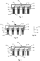
- Fig. 1 schematically illustrates a cross section of a brush electrode, in accordance with an example.
- Brush electrode 10 includes a plurality of strand electrodes 12. Although the cross sectional view of Fig. 1 shows a uniform linear array of strand electrodes 12 for convenience, it should be understood that strand electrodes 12 of a typical brush electrode 10 may be arranged in a two dimensional pattern (e.g., rectangular, circular, polygonal, oval, or other two-dimensional arrangement). A pattern of strand electrodes 12 may include rows, circles, or other arrangements. Strand electrodes 12 may be irregularly or non-uniformly distributed on brush electrode 10.
- each strand electrode 12 is configured to be placed against a skin surface 11.
- Strand electrodes 12 may be configured to adhere to, to absorb, to adsorb, or to otherwise hold a conductive substance, e.g., in the form of an electrolyte solution for conducting ion charges through the electrolyte solution to skin surface 11.
- each strand electrode 12 may be at least partially electrically conductive.
- Strand electrodes 12 may be configured to facilitate an electrolysis interface with the conductive substance.
- Brush electrode 10 includes electrode casing 15.
- electrode casing 15 may be configured to isolate all parts of strand electrodes 12, e.g., except for exposed distal ends of strand electrodes 12, from contact with any other objects.
- Electrode casing 15 may be configured to partially or fully isolate strand electrodes 12 e.g., except for exposed distal ends of strand electrodes 12, as well as other internal components of brush electrode 10 from contact with an ambient atmosphere.
- electrode casing 15 may function to prevent contact with external objects or with components of the atmosphere (e.g., moisture, suspended particles, or other components of the ambient atmosphere) from interfering with operation of brush electrode 10.
- Dimensions of electrode casing 15 may range from having a length of up to 5 mm, a width of up to 5 mm, and a thickness of up to 1 mm, to having a length of up to 100 mm, a width of up to 100 mm, and a thickness of up to 40 mm (or other ratios between length, width and thickness).
- Electrode base 16 may be incorporated into, or attachable to, electrode casing 15.
- electrode base 16 may include an arrangement of openings through which each strand electrode 12 may extend distally.
- electrode base 16 may be configured to hold clusters of strand electrodes 12 in a particular arrangement of clusters.
- Electrode base 16 may be elastic, rigid, or pliable. In some cases, electrode base 16 may be electrically conductive, for example, made of aluminum or another metal, conductive plastic or silicone, or another conductive material. In some cases, electrode base 16 may be made of a nonconductive plastic, silicone, or other nonconductive material. In some cases, electrode base 16 may be made of a combination of one or more materials, including, but not limited to, materials mentioned above. Electrode base 16 may be circular, rectangular, or otherwise shaped, with a surface area in the range of about 1square centimeter to about 40 square centimeters. For example, a size and shape of electrode base 16, or of brush electrode 10, may be selected to approximately match (e.g., such that strand electrodes 12 cover) a target region of the skin surface to which brush electrode 10 is to be applied.
- all strand electrodes 12 extended distally outward in a direction that is substantially perpendicular to electrode base 16. According to the invention, some or all of strand electrodes 12 extend distally outward from electrode base 16 at an oblique angle to electrode base 16.
- each strand electrode 12 may extend distally outward from electrode base 16 by a distance that is no longer than 3 cm. In some cases, each strand electrode 12 may extend outward from electrode base 16 by less than 2 cm, e.g., between 1 cm and 2 cm.
- Strand electrodes 12 may be flexible, elastic, or plastic, e.g., depending on a material from which each strand electrode 12 is constructed, and on a lateral thickness of each strand electrode 12.
- strand electrode 12 may be constructed of, or may include, conductive or nonconductive PA 6 nylon, PA 6,6 nylon, PA 6,10 nylon, PA 6,12 nylon, or viscose.
- a strand electrode 12 may be made of Thunderon TM , silicone, polyethylene or other polymer, elastomer, metal, agave bristle, animal hair, or other materials.
- Thunderon TM silicone, polyethylene or other polymer, elastomer, metal, agave bristle, animal hair, or other materials.
- strand electrodes 12 may be coated with a conductive material.
- strand electrode 12 is not conductive but is coated with a conductive material.
- a lateral thickness (e.g., diameter or other representative distance from one side of a strand electrode 12 to another) may range from 0.01 mm to 1 mm, e.g., in a range of lateral thickness from about 0.05 mm to about 0.8 mm, or, more particularly, from about 0.15 mm to about 0.6 mm.
- a strand electrode 12 may have another lateral thickness.
- a density of an arrangement of strand electrodes 12, e.g., on a surface of electrode base 16, may range from about 20 strand electrodes 12 per square centimeter of surface area to about 200 strand electrodes 12 per square centimeter of surface area. In some cases, the density may be selected in accordance with lateral thickness of each strand electrode 12.
- Strand electrodes 12 may be made of a material with a volume resistivity ranging from about 10 8 ⁇ -cm to less than 10 3 ⁇ -cm. Similarly, surface resistivity may range from about 10 8 ⁇ /square to less than 10 3 ⁇ /square.
- strand electrode 12 made of different materials, or otherwise having different properties or characteristics, may be included in a single brush electrode 10.
- Each strand electrode 12 may be electrically connected to an external device.
- the external device may be configured to generate an electrical signal, to receive an electrical signal, or both.
- the external device may be wearable or other portable device, or may be a non-portable, e.g., desktop or other fixed, device.
- the external device may be battery powered, may be connected to a computer or computing circuitry, or may be otherwise powered.
- each strand electrode 12 of brush electrode 10 may be held, e.g., by electrode base 16, in electrical contact with electrode conductor 14.
- electrode conductor 14 may be in the form of one or more plates or bars that are constructed of a conducting metal, polymer, or other conducting material. The plates or bars of electrode conductor 14 may be in electrical contact with one another, e.g., directly or via a common conductor to which all of the plates or bars are electrically connected.
- electrode conductor 14 may include two or more conducting plates or bars that are not electrically connected to one another.
- electrode conductor 14 may be connected via internal conductor 17 (e.g., that includes one or more conducting wires, cables, or bars) to external connector 18.
- external connector 18 may include a simple male snap connector. In other cases, external connector 18 may include another type of connector.
- External connector 18 may be connected to an external device by a device connector 20, e.g., that is connected to the external device by device connection 22.
- device connector 20 may be in the form of a female snap connector.
- device connector 20 may represent another type of connector.
- device connector 20 may include electrical or electronic circuitry.
- Device connection 22 may include an electrical cable, or another type of wired or wireless connection to the external device.
- strand electrodes 12 may be arranged on electrode base 16 in clusters of densely packed strand electrodes 12, with neighboring clusters being separated by gaps with no strand electrodes.
- the arrangement in clusters may facilitate holding of a conductive substance, e.g., by capillary forces between the surfaces of different strand electrodes 12 in a cluster.
- the facilitated holding of the conductive substance may increase or facilitate conductivity between strand electrodes 12 and a skin surface 11.
- Fig. 2 schematically illustrates a cross section of a brush electrode having strand electrodes arranged in clusters in the form of tufts held in place by staples.
- strand electrodes 12 are arranged in clusters in the form of electrode tufts 32.
- a plurality of strand electrodes 12 in each electrode tuft 32 are connected to one another at their proximal ends.
- the proximal ends of each strand electrode 12 in an electrode tuft 32 may be formed by bending or folding a single strand (e.g., that is approximately twice as long as each strand electrode 12) at proximal bend 35 to form two strand electrodes 12.
- An electrode tuft 32 may be otherwise formed by a plurality of strand electrodes 12.
- Tuft staple 34 may provide an electrical connection between each strand electrode 12 of electrode tuft 32 and electrode conductor 14.
- tuft staple 34 may include a wire loop that surrounds both proximal bend 35 and connects to electrode conductor 14 or another part of electrode base 16 or of electrode casing 15.
- a tuft staple may be U-shaped. Such a U-shaped staple may be configured such as the base of the U-shape holds proximal bend 35 of each electrode tuft 32 to (e.g., in electrical contact with) electrode base 16 when the arms of the U-shape are inserted into electrode base 16.
- Each pair of neighboring electrode tufts 32 is separated by a cluster gap 28.
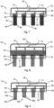
- Fig. 3 schematically illustrates a cross section of a brush electrode having clusters of strand electrodes that are held in place by ferrules.
- Each electrode ferrule 36 is configured to hold in place within electrode base 16 the proximal ends of a plurality of strand electrodes 12 of an electrode cluster 30.
- at least an interior part of electrode ferrule 36 may be electrically conducting.
- Each electrode ferrule 36 may be connected via ferrule connector 38 to electrode conductor 14, or otherwise to an external device.
- electrode ferrule 36 may connect strand electrodes 12 in each electrode cluster 30 (e.g., via internal conductor 17 and external connector 18) to the external device.
- Each pair of neighboring electrode clusters 30 is separated by a cluster gap 28.
- the number of strand electrodes 12 in each electrode cluster 30 may range from 5 strand electrodes 12 to more than 20.
- the lateral thickness of each electrode cluster 30 may be circular or oval, ranging from about 0.5 mm to about 4 mm, and may have a cross-section area of in the range of about 1 square millimeter to about 40 square millimeters.
- the length of an electrode cluster 30 may range from about 5 mm to about 20 mm.
- a density of a distribution of electrode clusters 30, e.g., on a distal surface of electrode base 16, may range from less than 2 electrode clusters 30 per square centimeter to 100 electrode clusters 30 per square centimeter.
- a representative length of cluster gap 28 (e.g., a minimum distance between adjacent electrode clusters 30) may range from about 0.5 mm to about 8 mm.
- a distal face of electrode cluster 30 may be substantially flat.
- different strand electrodes 12 of a single electrode cluster 30 may have different lengths.
- a distal face 33 of electrode cluster 30 may be substantially flat, perpendicular to strand electrodes 12, and parallel to electrode base 16.
- strand electrodes 12 of different lengths may be arranged to form a distal face that is planar but tilted, convex, or otherwise shaped.
- a single electrode cluster 30 may include strand electrodes 12 of different materials and dimensions.
- a brush electrode 10 may be configured to hold a conductive substance.
- the conductive substance may be applied by a user of brush electrode 10, e.g., by dipping strand electrodes 12, or an electrode cluster 30, into a conductive substance in the form of a liquid or gel (e.g., an electrolyte solution or other conductive substance in the form of liquid or gel).
- a brush electrode 10 may be provided by a producer or vendor of brush electrode 10 with a conductive substance already applied to strand electrodes 12 or to electrode clusters 30 (e.g., within a sealed container, envelope, or packaging.
- Fig. 4 schematically illustrates a cross section of a brush electrode as shown in Fig. 3 , with an electrolyte solution adhering to the clusters of conductive strand electrodes.
- a strand electrode or a part of a strand electrode, is considered to be conductive when constructed of an electronically conductive material that is configured to conduct electrical current in the form of electrons (e.g., such as a metal or other electronically conductive substance).
- an electronically conductive material that is configured to conduct electrical current in the form of electrons (e.g., such as a metal or other electronically conductive substance).
- Each electrode cluster 30 is shown as holding conductive substance 40 among electronically conductive strand electrodes 31.
- conductive substance 40 may be held within electrode cluster 30 by capillary forces among electronically conductive strand electrodes 31.
- electronically conductive strand electrodes 31 may be assumed to be conductive so as to facilitate electrolysis, e.g., within conductive substance 40.
- Electrodes may be included in a brush electrode 10 whose strand electrodes are configured to hold a conductive substance 40.
- an electrode cluster 30 includes approximately 40 strand electrodes (e.g., electrically conductive or otherwise), each about 1.2 mm long with a diameter of about 0.3 mm.
- the strand electrodes may be made of or may include conductive nylon PA6.
- the structure of electrode cluster 30 is such that a liquid electrolyte may be held between the strand electrodes by physical or chemical properties of the electrolyte, properties of the surfaces of the strand electrodes, structural properties of electrode cluster 30 (e.g., density or another property of the distribution of the strand electrodes), or a combination of these properties.
- the strand electrodes may be elastic. Therefore, placing brush electrode 10 on a target region of skin surface 11 may cause the strand electrodes to bend to accommodate any curvature or other topography of skin surface 11 while continuing to hold the electrolyte.
- the elasticity may enable the strand electrodes to move together without separating from one another, so that at least some of the electrolyte remains held between neighboring strand electrodes to facilitate electrolysis and ionic conduction of an ionic electric signal.
- the elasticity of the strand electrodes may be sufficiently weak (e.g., weaker than physical forces, e.g., capillary forces or surface tension, holding a liquid electrolyte between neighboring strand electrodes) such that a change in the position of one or more strand electrodes, for example by bending, may affect one or more neighboring or adjacent strand electrodes to change position in a similar manner (e.g., by a force transmitted via an electrolyte or other liquid held among the strand electrodes).
- sufficiently weak e.g., weaker than physical forces, e.g., capillary forces or surface tension, holding a liquid electrolyte between neighboring strand electrodes
- Fig. 5A schematically illustrates a variant of a cross section of a brush electrode as shown in Fig. 4 , with segmented strand electrodes that are partially electrically conductive and partially nonconductive.
- Fig. 5B schematically illustrates a segmented strand electrode of the brush electrode shown in Fig. 5A .
- a strand electrode, or part of a strand electrode is referred to as nonconductive when that strand electrode, or that part of a strand electrode, does not conduct electrons.
- the nonconductive strand electrode or part may be electrically insulating (e.g., as defined by a low electric conductivity), or may be configured to primarily conduct electricity by motion of ions.
- a strand electrode may be ionically conducting if constructed of an ionically conductive material, e.g., of an ion-conducting polymer such as poly(3,4-ethylenedioxythiophene) polystyrene sulfonate (PEDOT:PSS) or another ion-conducting polymer, or may be coated with a conductive substance 40 that is conductive of ions.
- an ionically conductive material e.g., of an ion-conducting polymer such as poly(3,4-ethylenedioxythiophene) polystyrene sulfonate (PEDOT:PSS) or another ion-conducting polymer, or may be coated with a conductive substance 40 that is conductive of ions.
- proximal segment 44 of each segmented strand electrode 42 is electrically conductive.
- the electrically conductive proximal segment 44 may facilitate electrolysis within conductive substance 40.
- Distal region 46 of each segmented strand electrode 42 is electrically nonconductive. Electrically nonconductive distal region 46 may provide a medium to enable conductive substance 40 and ionic charges to reach a skin surface 11 against which distal regions 46 are placed in contact.
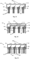
- Fig. 6 schematically illustrates a variant of a cross section of a brush electrode as shown in Fig. 4 , where each electrode cluster includes different types of strand electrodes.
- each electrode cluster 30 includes both conductive electronically conductive strand electrodes 31, and nonconductive strand electrodes 48.
- conductive electronically conductive strand electrodes 31 may facilitate electrolysis, e.g., in conductive substance 40.
- Nonconductive strand electrodes 48 may function as a medium to enable conductive substance 40 to reach skin surface 11.
- Nonconductive strand electrodes 48 may be electrically insulating or may be ion conducting.
- different types of strand electrodes may have different mechanical characteristics, electrical characteristics, chemical characteristics, or may differ with regard to other types of characteristics.
- Fig. 7 schematically illustrates a variant of a cross section of a brush electrode as shown in Fig. 4 , where electrolysis is configured to occur at a proximal end of each strand electrode.
- conductive substance 40 is present within electrode base 16.
- conductive substance 40 may be present within each electrode ferrule 36, as shown, or elsewhere within electrode base 16.
- nonconductive strand electrodes 48 may be coated with conductive substance 40.
- nonconductive strand electrodes 48 may be ionically conductive (e.g., without conductive substance 40), or the strand electrodes may include electronically conductive strand electrodes 31 that are coated with conductive substance 40.
- Fig. 8 schematically illustrates an example of a cross section of a brush electrode that includes an electrolyte reservoir within the electrode casing.
- electrode conductor 14 in connected to a plurality of electrolysis electrodes 52.
- Each electrolysis electrode is configured to be at least partially immersed in an electrolyte within electrolyte reservoir 50.
- electrolyte reservoir 50 is enclosed in electrode casing 15 outside of electrode base 16. Alternatively or in addition, electrolyte reservoir 50 may be located within electrode base 16. Electrolysis may occur within electrolyte reservoir 50, e.g., at electrolysis electrodes 52.
- the strand electrodes may include nonconductive strand electrodes 48, e.g., that are ionically conducting. Alternatively or in addition, the strand electrodes may include electronically conductive strand electrodes 31 or resistive nonconductive strand electrodes 48 that covered by a conductive substance 40.
- strand electrodes or electrode clusters of a brush electrode 10 may be configured to facilitate contact of the distal ends of the strand electrodes with a skin surface 11.
- Fig. 9 schematically illustrates a variant of the cross section of a brush electrode shown in Fig. 3 , with strand electrodes having different lengths.
- outer electrode clusters 54a are located near a lateral edge of brush electrode 10, while inner electrode clusters 54b are located interior to (e.g., further away from an edge than) outer electrode clusters 54a.
- strand electrodes 56a of outer electrode clusters 54a are longer than strand electrodes 56b of inner electrode clusters 54b. This configuration may facilitate contact of the distal ends of strand electrodes 56a and 56b with a convex skin surface 11 (e.g., a head, limb, or other convex surface).
- inner strand electrodes 56b may be longer than outer strand electrodes 56a, e.g., to facilitate contact with a concave skin surface 11.
- a brush electrode 10 may include more than four electrode clusters (e.g., more than in the example shown). In such a case, the lengths of the strand electrodes in the electrode clusters may gradually increase or decrease with increasing distance from a center of that brush electrode 10.
- Fig. 10 schematically illustrates a variant of the cross section of a brush electrode shown in Fig. 3 , having a curved electrode base.
- curved electrode base 60 is concave (e.g., as viewed from the direction of a skin surface 11). Such a concave curved electrode base 60 may facilitate contact of the distal ends of strand electrodes 12 (e.g., where all strand electrodes 12 extend distally by equal lengths from a connection of each strand electrode 12 with concave curved electrode base 60) with a convex skin surface 11 (e.g., on a head, limb, or other convex surface).
- curved electrode base 60 may be convex, e.g., to facilitate contact of the distal ends of strand electrodes 12 with a concave skin surface 11 (e.g., at an inner joint in a limb or in the neck region).
- a brush electrode 10 may include both electrode clusters of different lengths and a curved electrode base 60.
- Fig. 11 schematically illustrates a variant of the cross section of a brush electrode shown in Fig. 3 , having tilted strand electrodes.
- strand electrodes 12 of each tilted electrode cluster 62 extend distally outward at an oblique angle to (e.g., the distal face of) electrode base 16.
- the tilt of each tilted electrode cluster 62 may facilitate penetration of hair to an underlying skin surface 11, or may increase comfort of a subject whose skin is contacted by strand electrodes 12.
- Fig. 12 schematically illustrates a variant of the cross section of a brush electrode shown in Fig. 11 , having strand electrodes that are tilted laterally outward.
- strand electrodes 12 of each outwardly tilted electrode cluster 64 are tilted laterally outward (e.g., such that their distal end of each strand electrode 12 is further from a center of brush electrode 10 than its proximal end), each at an oblique angle to (e.g., the distal face of) electrode base 16.
- the laterally outward tilt may, in addition to facilitating hair penetration and promoting comfort, may contribute to stability of placement of brush electrode 10 on a skin surface 11. For example, the outward lateral tilt may impede lateral sliding of brush electrode 10 across skin surface 11.
- outwardly tilted electrode cluster 64 may have other orientations.
- each outwardly tilted electrode cluster 64 may also have an azimuthal tilt or slant.
- the azimuthal slant may, in some cases, enable placement of brush electrode 10a skin surface 11 with a lateral twisting motion. Such an azimuthal slant may further facilitate hair penetration and contact of strand electrodes 12 with a skin surface 11.
- different parts of a brush electrode 10 may be configured to apply or sense different electrical signals, or to facilitate placement of different brush electrodes 10 in close proximity to one another, e.g., to facilitate application or sensing of different electrical signals.
- Fig. 13 schematically illustrates a variant of the cross section of a brush electrode shown in Fig. 3 , configured to separately connect each electrode cluster to an external device.
- each electrode cluster 30 is connected to a separate external connector 58 via a separate internal conductor 57.
- Each external connector 58 may be separately connected to a different external device, or to a different port or connector of the external device.
- a different electrical signal may be separately applied to each electrode cluster 30, or may be separately sensed via each electrode cluster 30.
- an electrical signal may be applied to one or more electrode clusters 30, while an electrical signal may be concurrently sensed by one or more other electrode clusters 30.
- groups of two or more electrode clusters 30 may be connected to different external connectors 58.
- Fig. 14 schematically illustrates a variant of the cross section of a brush electrode shown in Fig. 3 , with isolating barriers.
- Isolating barriers 68 may be electrically insulating. Isolating barriers 68 may enable placement of two brush electrodes 10 in close proximity to one another. In this case, isolating barriers 68 may prevent contact between strand electrodes 12 or conductive substances 40 of adjacent brush electrodes 10. Isolating barriers 10 may include a hydrophobic material to inhibit passage or water or of water-based substances, or may be water absorptive to absorbing any electrolyte that may otherwise seep between isolating barriers 68 and skin surface 11.
- Fig. 15 schematically illustrates a variant of the cross section of a brush electrode shown in Fig. 13 , having isolating barriers between electrode clusters.
- Isolating barriers 68 may prevent contact between strand electrodes 12 of neighboring electrode clusters 30. This may be advantageous especially when a different electrical signal is applied to, or is sensed by, each electrode cluster 30.
- electrical ionic contact between strand electrodes 12 and a skin surface 11 may be facilitated by connecting the distal ends of groups of one or more strand electrodes 12 to an ionically conducting tip.
- Fig. 16 schematically illustrates a variant of the cross section of a brush electrode shown in Fig. 3 , where the distal ends of groups of strand electrodes within a single electrode cluster terminate in an ion-conducting tip.
- each group of neighboring strand electrodes 12 within an electrode cluster 30 terminates in a single ion-conducting tip 70.
- strand electrodes 12 may be electronically conductive and ion-conducting tip 70 may be made of an ionically conductive material.
- Fig. 17 schematically a variant of the cross section of a brush electrode shown in Fig. 3 , where all strand electrodes in an electrode cluster terminate in a single ion-conducting tip.
- Distal ends of all strand electrodes 12 in a single electrode cluster 30 terminate in a single ion-conducting cluster tip 71.
- Fig. 18 schematically illustrates variants of electrode clusters of the cross section of a brush electrode shown in Fig. 17 .
- interwoven electrode cluster 72 may include strand electrodes 12 that are braided, twisted together, or otherwise interwoven or interlocked.
- partial sleeve 74 In electrode cluster 30a, distal segments of strand electrodes 12 are covered by partial sleeve 74. Partial sleeve 74 may enable wetting of the distal segments with an electrolyte without wetting skin surface 11. The electrolyte may be introduced at a proximal end of partial sleeve 74.
- partial sleeve 74 may be constructed of silicone, nylon, or another material that is flexible and impermeable to an electrolyte.
- full sleeve 76 may enable wetting of the entire lengths of strand electrodes 12 without wetting skin surface 11.
- the electrolyte may be introduced into full sleeve 76, e.g., from within electrode base 16 or elsewhere within electrode casing 15.
- full sleeve 76 may be constructed of silicone, nylon, or another material that is flexible and impermeable to an electrolyte.
- Strand electrodes may have various forms, e.g., in addition to those of electronically conductive strand electrode 31, segmented strand electrode 42, and nonconductive strand electrode 48, described above.
- Fig. 19 schematically illustrates variants in the forms of longitudinal cross sections strand electrodes for a brush electrode as shown in Fig. 1 .
- Porous strand electrode 80 may be constructed of a porous material, e.g., to facilitate adherence of a conductive substance 40.
- Braided strand electrode 82 may be constructed of a plurality of braided or interwoven thin strands, e.g., to enable absorption of an electrolyte.
- a diameter or other lateral dimension of non-uniform profile strand electrode 84 may vary along its length, either monotonically, as in the example shown, or otherwise.
- Tipped strand electrode 86 may include an ion-conducting electrode tip 88.
- Strand electrodes may be constructed with different transverse cross-sectional shapes.
- Fig. 20 schematically illustrates variants of a transverse cross-sectional shape of a strand electrode for a brush electrode as shown in Fig. 1 .
- Cross sectional shapes may include, for example, solid circular 90, porous circular 92 (e.g., to enable absorption of an electrolyte), serrated 94 (e.g., to facilitate adsorption of an electrolyte), hollow circular 96 (e.g., to enable holding an electrolyte within the strand electrode), trefoil 98, triangular 100 (or other regular polygonal), cross-shaped 102 (or other irregular polygonal), or other shapes (e.g., oval, hollow, porous, or solid variants, or other shapes, such as ovals or other shapes).
- Selection of a form of a strand electrode may be determined, at least in part, by various electrical, chemical, or mechanical properties for a particular application.
- electrode base 16 has been shown in cross section in Figs. 1-18 , electrode base 16 typically extends in two lateral dimensions (e.g., length and width, in addition to its thickness or height).
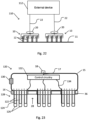
- Fig. 21 schematically illustrates a face of an electrode base of a brush electrode as shown in cross section in Fig. 3 .
- Electrode base face plate 104 is configured to cover a distal face of electrode base 16 (e.g., a face that faces skin surface 11 when in use). Each electrode cluster opening 106 is configured to enable an electrode cluster 30 to extend distally outward through electrode base face plate 104. Spaces between electrode cluster openings 106 may determine the sizes of cluster gaps 28.
- electrode cluster openings 106 are arranged in a rectangular array, other arrangements are possible.
- the arrangement and distribution (e.g., diameter or other lateral size, spacing between, or other characteristics of the arrangement or distribution) of electrode cluster openings 106 may be selected as appropriate to a particular application of a brush electrode 10.
- Fig. 22 schematically illustrates a system that includes a plurality of brush electrodes, in accordance with an example.
- Brush electrode system 110 includes an external device 112 that is connected to a plurality of brush electrodes 10.
- External device 112 may include one or more devices.
- a device of external device 112 may be configured to generate one or more electrical signals that may be applied to skin surface 11 via brush electrodes 10.
- a device of external device 112 may be configured to sense an electrical signal (e.g., an EEG signal or other signal) that is generated within a body and that may be detected by a brush electrode 10 in contact with skin surface 11.
- an electrical signal e.g., an EEG signal or other signal
- Each brush electrode 10 may be configured to enable identification by external device 112.
- an identification mechanism may include application of Inter-Integrated Circuit (I 2 C) technology, or may include providing each brush electrode 10 with a unique impedance footprint that is identifiable by external device 112.
- the identification mechanism or a database that is accessible by a processor of external device 112 may enable identification of one or more features or characteristics of each brush electrode 10. Such features and characteristics may include, for example, contact area, configuration of strand electrodes 12, or other features or characteristics.
- external device 112 may be connected by one or more device connections 22 to one or more device connectors 20.
- Each device connector 20 may be connected to a separate brush electrode 10.
- Fig. 23 schematically illustrates a brush electrode with hollow strand electrodes, in accordance with an example.
- control circuitry 132 may be electrically connected to each cluster 128 by cluster conductor 134.
- Each hollow strand electrode 122 has a hollow core and is coated with insulating coating 124. Insulating coating 124 may prevent electrical contact between adjacent hollow strand electrodes 122. A distal end of each hollow strand electrode 122 terminates in an ion-conducting tip 126.
- electrolyte may be introduced into electrode casing 15 via electrolyte orifice 130.
- electrolyte orifice 130 may be configured to enable electrolyte to flow into electrode casing 15, and to impede or prevent outflow of electrolyte from electrode casing 15.
- the electrolyte may flow from electrode casing 15 into the hollow core of each hollow strand electrode 122. Thus, electrolysis may occur within each hollow strand electrode 122.
- the ionic current may be conducted via ion-conducting tip 126 into a skin surface with which ion-conducting tip 126 is in contact.
Landscapes
- Health & Medical Sciences (AREA)
- Life Sciences & Earth Sciences (AREA)
- Animal Behavior & Ethology (AREA)
- Veterinary Medicine (AREA)
- Public Health (AREA)
- Engineering & Computer Science (AREA)
- Biomedical Technology (AREA)
- General Health & Medical Sciences (AREA)
- Surgery (AREA)
- Molecular Biology (AREA)
- Physics & Mathematics (AREA)
- Medical Informatics (AREA)
- Heart & Thoracic Surgery (AREA)
- Pathology (AREA)
- Biophysics (AREA)
- Nuclear Medicine, Radiotherapy & Molecular Imaging (AREA)
- Radiology & Medical Imaging (AREA)
- Cardiology (AREA)
- Electrotherapy Devices (AREA)
- Printers Or Recording Devices Using Electromagnetic And Radiation Means (AREA)
- Semiconductor Memories (AREA)
- Led Devices (AREA)
Claims (13)
- Bürstenelektrode (10), umfassend:eine Elektrodenbasis (16), die mit einer externen Vorrichtung, die dazu ausgestaltet ist, ein elektrisches Signal zu erzeugen oder ein elektrisches Signal zu empfangen, verbindbar ist; undeine Mehrzahl von Drahtelektroden (12), die sich von der Elektrodenbasis (16) nach außen erstrecken und dazu ausgestaltet sind, sich zu biegen, wobei ein distales Ende jeder Drahtelektrode dazu ausgestaltet ist, mit einer Hautoberfläche in Kontakt zu stehen,wobei die Mehrzahl von Drahtelektroden zu einer Mehrzahl von Clustern (32) von Drahtelektroden geclustert sind, wobei benachbarte Cluster der Mehrzahl von Clustern voneinander durch Zwischenräume ohne jede Drahtelektrode getrennt und dazu ausgestaltet sind, einen Elektrolyt zu enthalten, um eine Ionenleitung des elektrischen Signals zu oder von der Hautoberfläche zu erleichtern, undwobei die Drahtelektroden sich von der Elektrodenbasis in einem schiefen Winkel zu der Elektrodenbasis nach außen erstrecken.
- Bürstenelektrode nach Anspruch 1, wobei ein Cluster (32) der Mehrzahl von Clustern durch eine Klammer (34) oder eine Hülse (36) an der Basis gehalten wird.
- Bürstenelektrode nach Anspruch 2, wobei die Mehrzahl von Clustern mit einem einzigen äußeren Verbinder (18) zum Verbinden mit der äußeren Vorrichtung elektrisch verbunden sind.
- Bürstenelektrode nach Anspruch 2, wobei mindestens zwei Cluster der Mehrzahl von Clustern mit verschiedenen äußeren Verbindern (58) zum separaten Verbinden mit der externen Vorrichtung verbunden sind.
- Bürstenelektrode nach einem der Ansprüche 1 bis 4, ferner umfassend eine isolierende Barriere (68) zum elektrischen Isolieren zweier Cluster der Mehrzahl von Clustern voneinander.
- Bürstenelektrode nach einem der Ansprüche 1 bis 5, wobei die Mehrzahl von Drahtelektroden dazu ausgestaltet ist, einen Elektrolyt durch Kapillarkräfte an sich zu halten.
- Bürstenelektrode nach einem der Ansprüche 1 bis 6, wobei eine Drahtelektrode der Mehrzahl von Drahtelektroden einen hohlen Kern umfasst, der dazu ausgestaltet ist, mit einem Elektrolyt gefüllt zu werden, oder dazu ausgestaltet ist, den Elektrolyt zu absorbieren oder zu adsorbieren.
- Bürstenelektrode nach einem der Ansprüche 1 bis 7, wobei eine Drahtelektrode der Mehrzahl von Drahtelektroden elektrisch widerstandsbehaftet oder ionenleitend ist.
- Bürstenelektrode nach einem der Ansprüche 1 bis 8, wobei ein proximales Segment einer Drahtelektrode der Mehrzahl von Drahtelektroden elektronenleitend ist und ein distales Segment dieser Drahtelektrode elektrisch widerstandsbehaftet oder ionenleitend ist.
- Bürstenelektrode nach einem der Ansprüche 1 bis 9, ferner umfassend einen Elektrolytvorratsbehälter.
- Bürstenelektrode nach einem der Ansprüche 1 bis 10, wobei die Mehrzahl von Drahtelektroden Drahtelektroden unterschiedlicher Längen umfasst.
- Bürstenelektrode nach einem der Ansprüche 1 bis 11, wobei die Elektrodenbasis gebogen ist.
- Bürstenelektrode nach Anspruch 1, wobei die Drahtelektroden seitlich nach außen geneigt sind.
Applications Claiming Priority (2)
| Application Number | Priority Date | Filing Date | Title |
|---|---|---|---|
| US201662434954P | 2016-12-15 | 2016-12-15 | |
| PCT/IL2017/050934 WO2018109758A1 (en) | 2016-12-15 | 2017-08-22 | Brush electrode |
Publications (4)
| Publication Number | Publication Date |
|---|---|
| EP3554356A1 EP3554356A1 (de) | 2019-10-23 |
| EP3554356A4 EP3554356A4 (de) | 2020-06-10 |
| EP3554356B1 true EP3554356B1 (de) | 2024-11-13 |
| EP3554356C0 EP3554356C0 (de) | 2024-11-13 |
Family
ID=62558149
Family Applications (1)
| Application Number | Title | Priority Date | Filing Date |
|---|---|---|---|
| EP17879834.4A Active EP3554356B1 (de) | 2016-12-15 | 2017-08-22 | Bürstenelektrode |
Country Status (5)
| Country | Link |
|---|---|
| US (3) | US11647937B2 (de) |
| EP (1) | EP3554356B1 (de) |
| CN (1) | CN110225712A (de) |
| IL (2) | IL300675A (de) |
| WO (1) | WO2018109758A1 (de) |
Families Citing this family (17)
| Publication number | Priority date | Publication date | Assignee | Title |
|---|---|---|---|---|
| US11850052B2 (en) | 2014-01-28 | 2023-12-26 | Medibotics Llc | Dry EEG electrode for use on a hair-covered portion of a person's head |
| US12201427B2 (en) | 2012-06-14 | 2025-01-21 | Medibotics Llc | Headband with brain activity sensors |
| IT201900008424A1 (it) * | 2019-06-10 | 2020-12-10 | Wow Activewear Tech S R L S | Indumento perfezionato |
| CN113905672B (zh) * | 2019-06-17 | 2023-08-29 | 株式会社岛津制作所 | 光计测装置以及探针支架套件 |
| CN114206219B (zh) * | 2019-06-18 | 2025-02-11 | 脑电感觉有限公司 | Eeg信号测量方法及系统 |
| US12446815B2 (en) * | 2020-02-07 | 2025-10-21 | Nok Corporation | Biological electrode |
| WO2021191930A1 (en) * | 2020-03-25 | 2021-09-30 | Sattva Medtech Pvt Ltd | A medical electrode and system thereof |
| JP6966812B1 (ja) * | 2020-08-06 | 2021-11-17 | 有限会社G.Mコーポレーション | 皮膚刺激ブラシ |
| US20230404841A1 (en) * | 2020-10-16 | 2023-12-21 | Jcraft Co., Ltd. | Brush |
| US20220160576A1 (en) * | 2020-11-23 | 2022-05-26 | L'oreal | Portable hair and scalp treatment device with conductive bristles |
| CN113135473B (zh) * | 2021-03-02 | 2022-09-16 | 玉林市红十字会医院 | 心电监护仪导联线收纳装置 |
| CN113812953A (zh) * | 2021-09-16 | 2021-12-21 | 北京脑陆科技有限公司 | 毛刷式电极 |
| CN113974637B (zh) * | 2021-12-23 | 2022-04-15 | 天津大学 | 高度舒适的新型弹性脑电干电极、脑电设备及应用系统 |
| CN114176599A (zh) * | 2021-12-27 | 2022-03-15 | 深圳迈瑞动物医疗科技有限公司 | 应用于动物的心电采集装置 |
| KR102721099B1 (ko) * | 2022-03-04 | 2024-10-23 | 인하대학교 산학협력단 | 측두근 자극기 |
| DE112023001482T5 (de) * | 2022-03-22 | 2025-01-09 | Ntt Research, Inc. | Flexible trockenelektroden |
| CN117679005B (zh) * | 2024-01-23 | 2024-09-06 | 中国科学院半导体研究所 | 表贴式无线肌肉阻抗图检测系统及表贴式无线电刺激系统 |
Citations (1)
| Publication number | Priority date | Publication date | Assignee | Title |
|---|---|---|---|---|
| US20160166830A1 (en) * | 2013-07-29 | 2016-06-16 | Kural Corp. | Therapeutic electron and ion transfer via half-cell |
Family Cites Families (14)
| Publication number | Priority date | Publication date | Assignee | Title |
|---|---|---|---|---|
| US1664457A (en) * | 1925-09-18 | 1928-04-03 | Milan Francis Pratt | Electrical hair or massage brush |
| DE2713891A1 (de) * | 1977-03-29 | 1978-10-12 | Schweizer Helgi Jon Dr | Vorrichtung zur herstellung und anwendung rhythmischer reizstrukturen |
| GB2274396B (en) * | 1993-01-26 | 1996-12-04 | British Aerospace | An electrode assembly |
| US20020177767A1 (en) | 2000-05-16 | 2002-11-28 | Steve Burton | Sensor for biopotential measurements |
| US7326204B2 (en) | 2004-01-16 | 2008-02-05 | St. Jude Medical, Atrial Fibrillation Division, Inc. | Brush electrode and method for ablation |
| WO2006001276A1 (ja) * | 2004-06-25 | 2006-01-05 | Olympus Corporation | 脳波検出用電極装置およびパッケージ |
| KR100634546B1 (ko) * | 2005-06-30 | 2006-10-13 | 삼성전자주식회사 | 생체신호 측정용 전극 |
| US20070105984A1 (en) | 2005-11-07 | 2007-05-10 | Griffin Elizabeth R | Composition comprising cellulose and polyvinyl chloride polymer |
| WO2009134763A1 (en) | 2008-04-29 | 2009-11-05 | Board of Governors for Higher Education, State of Rhode Island and the Providence Plantations | Biomedical sensors usable on un-prepared contact surfaces |
| JP5589593B2 (ja) * | 2009-06-29 | 2014-09-17 | ソニー株式会社 | 生体信号測定用装具 |
| US8326396B2 (en) * | 2010-03-24 | 2012-12-04 | Brain Products Gmbh | Dry electrode for detecting EEG signals and attaching device for holding the dry electrode |
| WO2012088329A2 (en) * | 2010-12-21 | 2012-06-28 | Advanced Brain Monitoring, Inc. | Dry gel-conductive scaffold sensor |
| WO2015031510A1 (en) * | 2013-08-27 | 2015-03-05 | Halo Neuro, Inc. | Electrode system for electrical stimulation |
| CN105748065B (zh) * | 2016-01-21 | 2019-10-29 | 天津工业大学 | 一种保湿微针矩阵阵列表面生物电电极 |
-
2017
- 2017-08-22 EP EP17879834.4A patent/EP3554356B1/de active Active
- 2017-08-22 WO PCT/IL2017/050934 patent/WO2018109758A1/en not_active Ceased
- 2017-08-22 CN CN201780076926.0A patent/CN110225712A/zh active Pending
- 2017-08-22 IL IL300675A patent/IL300675A/en unknown
- 2017-08-22 US US16/469,207 patent/US11647937B2/en active Active
- 2017-08-22 IL IL267079A patent/IL267079B2/en unknown
-
2023
- 2023-03-13 US US18/120,427 patent/US12257058B2/en active Active
-
2025
- 2025-03-24 US US19/088,405 patent/US20250248635A1/en active Pending
Patent Citations (1)
| Publication number | Priority date | Publication date | Assignee | Title |
|---|---|---|---|---|
| US20160166830A1 (en) * | 2013-07-29 | 2016-06-16 | Kural Corp. | Therapeutic electron and ion transfer via half-cell |
Also Published As
| Publication number | Publication date |
|---|---|
| US20190328261A1 (en) | 2019-10-31 |
| US12257058B2 (en) | 2025-03-25 |
| IL300675A (en) | 2023-04-01 |
| EP3554356C0 (de) | 2024-11-13 |
| US11647937B2 (en) | 2023-05-16 |
| US20250248635A1 (en) | 2025-08-07 |
| IL267079A (en) | 2019-08-29 |
| IL267079B2 (en) | 2024-02-01 |
| CN110225712A (zh) | 2019-09-10 |
| EP3554356A4 (de) | 2020-06-10 |
| IL267079B1 (en) | 2023-10-01 |
| US20230210431A1 (en) | 2023-07-06 |
| EP3554356A1 (de) | 2019-10-23 |
| WO2018109758A1 (en) | 2018-06-21 |
Similar Documents
| Publication | Publication Date | Title |
|---|---|---|
| US12257058B2 (en) | Brush electrode | |
| EP3435859B1 (de) | Elektrodenanordnung | |
| US10463272B1 (en) | Physiological electrode assembly for fast application | |
| CN105492067B (zh) | 用于电刺激的电极系统 | |
| US5645063A (en) | Skin electrode having multiple conductive center members | |
| CN104068853B (zh) | 一种生物电电极 | |
| EP3033994B1 (de) | Elektrode zur erfassung von biopotential | |
| EP2717768A1 (de) | Elektrodenfühlerkit, elektrodenanordnung und topisches präparat zur herstellung eines elektrischen kontakts mit der haut, verwendung davon und verfahren zur elektroimpedanztomographie-bildgebung damit | |
| ES2908251T3 (es) | Aparato y método para realizar una electroencefalografía | |
| WO2010047599A1 (en) | Electrode assembly for medical purposes | |
| WO2016009424A1 (en) | Electrode headset grid and use thereof in the non-invasive brain stimulation and monitoring | |
| CN102894976B (zh) | 一种圆形阵列脑部电阻抗断层成像用电极 | |
| JP2022137320A (ja) | 生体情報測定用電極 | |
| CN103027674A (zh) | 生物信号检测电极和生物信号检测设备 | |
| US20230309888A1 (en) | Apparatus and method for hybrid biosensors | |
| Kim et al. | Microneedle-based high-density surface EMG interface with high selectivity for finger movement recognition | |
| WO2021254601A1 (en) | Three-dimensional electrode arrangement | |
| Geoffrey | I hereby declare that the thesis is my original work and it has been written by me in its entirety. I have duly acknowledged all the sources of information which have been used in the thesis. This thesis has also not been submitted for any degree in any university previously. | |
| PL68599Y1 (pl) | Elektroda do rejestracji potencjałów bioelektrycznych |
Legal Events
| Date | Code | Title | Description |
|---|---|---|---|
| STAA | Information on the status of an ep patent application or granted ep patent |
Free format text: STATUS: THE INTERNATIONAL PUBLICATION HAS BEEN MADE |
|
| PUAI | Public reference made under article 153(3) epc to a published international application that has entered the european phase |
Free format text: ORIGINAL CODE: 0009012 |
|
| STAA | Information on the status of an ep patent application or granted ep patent |
Free format text: STATUS: REQUEST FOR EXAMINATION WAS MADE |
|
| 17P | Request for examination filed |
Effective date: 20190715 |
|
| AK | Designated contracting states |
Kind code of ref document: A1 Designated state(s): AL AT BE BG CH CY CZ DE DK EE ES FI FR GB GR HR HU IE IS IT LI LT LU LV MC MK MT NL NO PL PT RO RS SE SI SK SM TR |
|
| AX | Request for extension of the european patent |
Extension state: BA ME |
|
| RIN1 | Information on inventor provided before grant (corrected) |
Inventor name: SHACOUR, RAMI Inventor name: SHAKOUR, GABRIEL Inventor name: SHAKOUR, EHAB Inventor name: BADRAN, YOUSEF |
|
| DAV | Request for validation of the european patent (deleted) | ||
| DAX | Request for extension of the european patent (deleted) | ||
| A4 | Supplementary search report drawn up and despatched |
Effective date: 20200511 |
|
| RIC1 | Information provided on ipc code assigned before grant |
Ipc: A61N 1/04 20060101ALI20200504BHEP Ipc: A61B 5/04 20060101AFI20200504BHEP Ipc: A61B 5/0478 20060101ALI20200504BHEP Ipc: A61N 1/32 20060101ALI20200504BHEP |
|
| STAA | Information on the status of an ep patent application or granted ep patent |
Free format text: STATUS: EXAMINATION IS IN PROGRESS |
|
| 17Q | First examination report despatched |
Effective date: 20221014 |
|
| REG | Reference to a national code |
Ref legal event code: R079 Ipc: A61N0001040000 Ref country code: DE Ref legal event code: R079 Ref document number: 602017086161 Country of ref document: DE Free format text: PREVIOUS MAIN CLASS: A61B0005040000 Ipc: A61N0001040000 |
|
| GRAP | Despatch of communication of intention to grant a patent |
Free format text: ORIGINAL CODE: EPIDOSNIGR1 |
|
| STAA | Information on the status of an ep patent application or granted ep patent |
Free format text: STATUS: GRANT OF PATENT IS INTENDED |
|
| RIC1 | Information provided on ipc code assigned before grant |
Ipc: A61B 5/291 20210101ALI20240517BHEP Ipc: A61N 1/32 20060101ALI20240517BHEP Ipc: A61N 1/04 20060101AFI20240517BHEP |
|
| INTG | Intention to grant announced |
Effective date: 20240611 |
|
| GRAS | Grant fee paid |
Free format text: ORIGINAL CODE: EPIDOSNIGR3 |
|
| GRAA | (expected) grant |
Free format text: ORIGINAL CODE: 0009210 |
|
| STAA | Information on the status of an ep patent application or granted ep patent |
Free format text: STATUS: THE PATENT HAS BEEN GRANTED |
|
| AK | Designated contracting states |
Kind code of ref document: B1 Designated state(s): AL AT BE BG CH CY CZ DE DK EE ES FI FR GB GR HR HU IE IS IT LI LT LU LV MC MK MT NL NO PL PT RO RS SE SI SK SM TR |
|
| REG | Reference to a national code |
Ref country code: GB Ref legal event code: FG4D |
|
| REG | Reference to a national code |
Ref country code: CH Ref legal event code: EP |
|
| REG | Reference to a national code |
Ref country code: IE Ref legal event code: FG4D |
|
| REG | Reference to a national code |
Ref country code: DE Ref legal event code: R096 Ref document number: 602017086161 Country of ref document: DE |
|
| U01 | Request for unitary effect filed |
Effective date: 20241212 |
|
| U07 | Unitary effect registered |
Designated state(s): AT BE BG DE DK EE FI FR IT LT LU LV MT NL PT RO SE SI Effective date: 20241220 |
|
| PG25 | Lapsed in a contracting state [announced via postgrant information from national office to epo] |
Ref country code: IS Free format text: LAPSE BECAUSE OF FAILURE TO SUBMIT A TRANSLATION OF THE DESCRIPTION OR TO PAY THE FEE WITHIN THE PRESCRIBED TIME-LIMIT Effective date: 20250313 Ref country code: HR Free format text: LAPSE BECAUSE OF FAILURE TO SUBMIT A TRANSLATION OF THE DESCRIPTION OR TO PAY THE FEE WITHIN THE PRESCRIBED TIME-LIMIT Effective date: 20241113 |
|
| PG25 | Lapsed in a contracting state [announced via postgrant information from national office to epo] |
Ref country code: ES Free format text: LAPSE BECAUSE OF FAILURE TO SUBMIT A TRANSLATION OF THE DESCRIPTION OR TO PAY THE FEE WITHIN THE PRESCRIBED TIME-LIMIT Effective date: 20241113 |
|
| PG25 | Lapsed in a contracting state [announced via postgrant information from national office to epo] |
Ref country code: NO Free format text: LAPSE BECAUSE OF FAILURE TO SUBMIT A TRANSLATION OF THE DESCRIPTION OR TO PAY THE FEE WITHIN THE PRESCRIBED TIME-LIMIT Effective date: 20250213 |
|
| PG25 | Lapsed in a contracting state [announced via postgrant information from national office to epo] |
Ref country code: GR Free format text: LAPSE BECAUSE OF FAILURE TO SUBMIT A TRANSLATION OF THE DESCRIPTION OR TO PAY THE FEE WITHIN THE PRESCRIBED TIME-LIMIT Effective date: 20250214 |
|
| PG25 | Lapsed in a contracting state [announced via postgrant information from national office to epo] |
Ref country code: PL Free format text: LAPSE BECAUSE OF FAILURE TO SUBMIT A TRANSLATION OF THE DESCRIPTION OR TO PAY THE FEE WITHIN THE PRESCRIBED TIME-LIMIT Effective date: 20241113 |
|
| PG25 | Lapsed in a contracting state [announced via postgrant information from national office to epo] |
Ref country code: RS Free format text: LAPSE BECAUSE OF FAILURE TO SUBMIT A TRANSLATION OF THE DESCRIPTION OR TO PAY THE FEE WITHIN THE PRESCRIBED TIME-LIMIT Effective date: 20250213 |
|
| PG25 | Lapsed in a contracting state [announced via postgrant information from national office to epo] |
Ref country code: SM Free format text: LAPSE BECAUSE OF FAILURE TO SUBMIT A TRANSLATION OF THE DESCRIPTION OR TO PAY THE FEE WITHIN THE PRESCRIBED TIME-LIMIT Effective date: 20241113 |
|
| PG25 | Lapsed in a contracting state [announced via postgrant information from national office to epo] |
Ref country code: SK Free format text: LAPSE BECAUSE OF FAILURE TO SUBMIT A TRANSLATION OF THE DESCRIPTION OR TO PAY THE FEE WITHIN THE PRESCRIBED TIME-LIMIT Effective date: 20241113 |
|
| PG25 | Lapsed in a contracting state [announced via postgrant information from national office to epo] |
Ref country code: CZ Free format text: LAPSE BECAUSE OF FAILURE TO SUBMIT A TRANSLATION OF THE DESCRIPTION OR TO PAY THE FEE WITHIN THE PRESCRIBED TIME-LIMIT Effective date: 20241113 |
|
| PLBE | No opposition filed within time limit |
Free format text: ORIGINAL CODE: 0009261 |
|
| STAA | Information on the status of an ep patent application or granted ep patent |
Free format text: STATUS: NO OPPOSITION FILED WITHIN TIME LIMIT |
|
| U20 | Renewal fee for the european patent with unitary effect paid |
Year of fee payment: 9 Effective date: 20250825 |
|
| 26N | No opposition filed |
Effective date: 20250814 |