EP3554104B1 - Procédé et système de détection et de création de périmètres virtuels - Google Patents
Procédé et système de détection et de création de périmètres virtuels Download PDFInfo
- Publication number
- EP3554104B1 EP3554104B1 EP19167606.3A EP19167606A EP3554104B1 EP 3554104 B1 EP3554104 B1 EP 3554104B1 EP 19167606 A EP19167606 A EP 19167606A EP 3554104 B1 EP3554104 B1 EP 3554104B1
- Authority
- EP
- European Patent Office
- Prior art keywords
- event
- network element
- value
- message
- geofence
- Prior art date
- Legal status (The legal status is an assumption and is not a legal conclusion. Google has not performed a legal analysis and makes no representation as to the accuracy of the status listed.)
- Active
Links
- 238000000034 method Methods 0.000 title claims description 56
- 238000001514 detection method Methods 0.000 title description 2
- 238000004891 communication Methods 0.000 claims description 37
- 230000008859 change Effects 0.000 claims description 3
- 230000008569 process Effects 0.000 description 27
- 238000007726 management method Methods 0.000 description 9
- 238000012544 monitoring process Methods 0.000 description 8
- 238000012545 processing Methods 0.000 description 7
- 238000010586 diagram Methods 0.000 description 6
- 230000001413 cellular effect Effects 0.000 description 5
- 238000005516 engineering process Methods 0.000 description 4
- 230000003287 optical effect Effects 0.000 description 3
- 239000000835 fiber Substances 0.000 description 2
- 230000006870 function Effects 0.000 description 2
- 238000004519 manufacturing process Methods 0.000 description 2
- 230000004044 response Effects 0.000 description 2
- 238000000926 separation method Methods 0.000 description 2
- 238000006467 substitution reaction Methods 0.000 description 2
- 239000004165 Methyl ester of fatty acids Substances 0.000 description 1
- 230000001133 acceleration Effects 0.000 description 1
- 230000004075 alteration Effects 0.000 description 1
- 230000002457 bidirectional effect Effects 0.000 description 1
- 239000002775 capsule Substances 0.000 description 1
- 230000001186 cumulative effect Effects 0.000 description 1
- 230000001419 dependent effect Effects 0.000 description 1
- 238000013461 design Methods 0.000 description 1
- 230000000694 effects Effects 0.000 description 1
- 230000007613 environmental effect Effects 0.000 description 1
- 239000000446 fuel Substances 0.000 description 1
- 238000012423 maintenance Methods 0.000 description 1
- 238000012986 modification Methods 0.000 description 1
- 230000004048 modification Effects 0.000 description 1
- 238000012806 monitoring device Methods 0.000 description 1
- 239000004065 semiconductor Substances 0.000 description 1
- 230000003068 static effect Effects 0.000 description 1
- 230000001360 synchronised effect Effects 0.000 description 1
- 238000012546 transfer Methods 0.000 description 1
Images


Classifications
-
- H—ELECTRICITY
- H04—ELECTRIC COMMUNICATION TECHNIQUE
- H04W—WIRELESS COMMUNICATION NETWORKS
- H04W4/00—Services specially adapted for wireless communication networks; Facilities therefor
- H04W4/02—Services making use of location information
- H04W4/021—Services related to particular areas, e.g. point of interest [POI] services, venue services or geofences
- H04W4/022—Services related to particular areas, e.g. point of interest [POI] services, venue services or geofences with dynamic range variability
-
- H—ELECTRICITY
- H04—ELECTRIC COMMUNICATION TECHNIQUE
- H04W—WIRELESS COMMUNICATION NETWORKS
- H04W4/00—Services specially adapted for wireless communication networks; Facilities therefor
- H04W4/02—Services making use of location information
- H04W4/021—Services related to particular areas, e.g. point of interest [POI] services, venue services or geofences
-
- H—ELECTRICITY
- H04—ELECTRIC COMMUNICATION TECHNIQUE
- H04W—WIRELESS COMMUNICATION NETWORKS
- H04W4/00—Services specially adapted for wireless communication networks; Facilities therefor
- H04W4/02—Services making use of location information
- H04W4/029—Location-based management or tracking services
-
- H—ELECTRICITY
- H04—ELECTRIC COMMUNICATION TECHNIQUE
- H04W—WIRELESS COMMUNICATION NETWORKS
- H04W4/00—Services specially adapted for wireless communication networks; Facilities therefor
- H04W4/30—Services specially adapted for particular environments, situations or purposes
- H04W4/35—Services specially adapted for particular environments, situations or purposes for the management of goods or merchandise
-
- H—ELECTRICITY
- H04—ELECTRIC COMMUNICATION TECHNIQUE
- H04W—WIRELESS COMMUNICATION NETWORKS
- H04W4/00—Services specially adapted for wireless communication networks; Facilities therefor
- H04W4/30—Services specially adapted for particular environments, situations or purposes
- H04W4/38—Services specially adapted for particular environments, situations or purposes for collecting sensor information
-
- H—ELECTRICITY
- H04—ELECTRIC COMMUNICATION TECHNIQUE
- H04W—WIRELESS COMMUNICATION NETWORKS
- H04W4/00—Services specially adapted for wireless communication networks; Facilities therefor
- H04W4/30—Services specially adapted for particular environments, situations or purposes
- H04W4/40—Services specially adapted for particular environments, situations or purposes for vehicles, e.g. vehicle-to-pedestrians [V2P]
- H04W4/44—Services specially adapted for particular environments, situations or purposes for vehicles, e.g. vehicle-to-pedestrians [V2P] for communication between vehicles and infrastructures, e.g. vehicle-to-cloud [V2C] or vehicle-to-home [V2H]
Definitions
- the present disclosure relates to the transportation of goods, and in particular relates to geographic indicators for the transportation of goods.
- Geofencing is a technique for monitoring and providing an alert in response to the movement of an electronic device, such as a computing device within a vehicle or a mobile device, into or out of a prescribed area around which a geofence is defined. A geofence is thus determined with reference to a geographical area. Location data from the electronic device is compared with coordinate ranges of the geofence to determine whether the electronic device is inside or outside the geofence.
- geofenced areas are typically done manually, which may be burdensome. Further, sometimes areas that are important to the company may not be properly configured with geofences. In other cases, the company may not know about areas that may be important to geofence.
- WO 2015/036578 A1 is related to a system and a method and a system flow for processing GPS event data to identify frequent stop locations.
- the present disclosure further provides a network element in accordance with the annexed independent network element claim.
- the present disclosure further provides a computer readable medium in accordance with the annexed independent computer readable medium claim.
- Important places are locations where a container or vehicle may be loaded, unloaded, stop for long periods of time, among other options.
- candidate geofences can be created in accordance with the embodiments below utilizing a trigger and voting or value system.
- each trigger has a value assigned to it.
- a network element may receive reports of trigger events and associated values for a geographic area, and when the cumulative associated values for the geographic area reach a predetermined threshold, the network element may signal to an operator or administrator that the geographic area is a candidate for a geofence.
- tracking events can be started at such locations.
- Such tracking events may include, but are not limited to, the entry into the geofenced area, exit from the geofenced area, extended stays within the geofenced area, door open events within the geofenced area, door closed events within the geofence area, among other such reporting events.
- Geofences may be missing for a variety of reasons.
- the geofence may not have been created during the initial creation of the geofenced regions for the company. This could be, for example, due to human error or based on the sheer number of geofences. For example, some companies may have thousands of geofences.
- a geofence may have failed to be created if a new, important location is suddenly utilized.
- such new location may be a rest area for drivers.
- subsequent logging may indicate to the administrators whether a driver is wasting time within such area.
- Areas that are used to transfer items, whether legitimately or illegitimately can also be marked. For example, if items are stolen from the vehicle at particular locations, then these areas may be marked as geofenced areas. A vehicle entering such area may cause an alarm at the operator based on the geofence.
- Other areas that may be marked include train stations, airports, other ports, among other options.
- geofences based on fleet operations
- geofences could be created for different industries utilizing the trigger value system described herein.
- the present disclosure is therefore not limited to fleet operations, but such fleet operations are merely provided as an illustration.
- sensor systems may be included on the vehicle and have a plurality of sensor apparatuses operating remotely from a central monitoring station to provide remote sensor data to a management or monitoring hub.
- a sensor system involves fleet management or cargo management systems.
- sensors may be placed on a trailer, shipping container or similar product to provide a central station with information regarding the container.
- information may include, but is not limited to, information concerning the current location of the trailer or shipping container, the temperature inside the shipping container or trailer, operational parameters such as tire pressure or engine temperature, that the doors on the shipping container or trailer are closed, whether a sudden acceleration or deceleration event has occurred, the tilt angle of the trailer or shipping container, among other data.
- the senor apparatus may be secured to a vehicle itself.
- vehicle can include any motorized vehicle such as a truck, tractor, car, boat, motorcycle, snow machine, among others, and can further include a trailer, shipping container or other such cargo moving container, whether attached to a motorized vehicle or not.
- a sensor apparatus may be any apparatus or computing device that is capable of providing data or information from sensors associated with the sensor apparatus to a central monitoring or control station.
- Sensors associated with the sensor apparatus may either be physically part of the sensor apparatus, for example a built-in global positioning system (GPS) chipset, or may be associated with the sensor apparatus through short range wired or wireless communications.
- GPS global positioning system
- a tire pressure monitor may provide information through a Bluetooth TM Low Energy (BLE) signal from the tire to the sensor apparatus.
- BLE Bluetooth TM Low Energy
- a camera may be part of the sensor apparatus or may communicate with a sensor apparatus through wired or wireless technologies. Other examples of sensors are possible.
- a central monitoring station may be any server or combination of servers that are remote from the sensor apparatus.
- the central monitoring station can receive data from a plurality of sensor apparatuses.
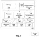
- FIG. 1 One sensor apparatus is shown with regard to Figure 1 .
- the sensor apparatus of Figure 1 is however merely an example and other mobile devices could equally be used in accordance with the embodiments of the present disclosure.
- Sensor apparatus 110 can be any computing device or network node.
- Such computing device or network node may include any type of electronic device, including but not limited to, mobile devices such as smartphones or cellular telephones. Examples can further include fixed or mobile devices, such as internet of things devices, endpoints, home automation devices, medical equipment in hospital or home environments, inventory tracking devices, environmental monitoring devices, energy management devices, infrastructure management devices, vehicles or devices for vehicles, fixed electronic devices, among others.
- Sensor apparatus 110 comprises a processor 120 and at least one communications subsystem 130 , where the processor 120 and communications subsystem 130 cooperate to perform the methods of the embodiments described herein.
- Communications subsystem 130 may, in some embodiments, comprise multiple subsystems, for example for different radio technologies.
- Communications subsystem 130 allows sensor apparatus 110 to communicate with other devices or network elements. Communications subsystem 130 may use one or more of a variety of communications types, including but not limited to cellular, satellite, Bluetooth TM , Bluetooth TM Low Energy, Wi-Fi, wireless local area network (WLAN), near field communications (NFC), ZigBee, wired connections such as Ethernet or fiber, among other options.
- communications types including but not limited to cellular, satellite, Bluetooth TM , Bluetooth TM Low Energy, Wi-Fi, wireless local area network (WLAN), near field communications (NFC), ZigBee, wired connections such as Ethernet or fiber, among other options.
- a communications subsystem 130 for wireless communications will typically have one or more receivers and transmitters, as well as associated components such as one or more antenna elements, local oscillators (LOs), and may include a processing module such as a digital signal processor (DSP).
- LOs local oscillators
- DSP digital signal processor
- SIM subscriber identity module
- USIM universal subscriber identity module
- IM identity module
- eUICC embedded Universal Integrated Circuit Card
- Processor 120 generally controls the overall operation of the sensor apparatus 110 and is configured to execute programmable logic, which may be stored, along with data, using memory 140 .
- Memory 140 can be any tangible, non-transitory computer readable storage medium, including but not limited to optical (e.g., CD, DVD, etc.), magnetic (e.g., tape), flash drive, hard drive, or other memory known in the art.
- sensor apparatus 110 may access data or programmable logic from an external storage medium, for example through communications subsystem 130 .
- sensor apparatus 110 may utilize a plurality of sensors, which may either be part of sensor apparatus 110 in some embodiments or may communicate with sensor apparatus 110 in other embodiments.
- processor 120 may receive input from a sensor subsystem 150 .
- sensors in the embodiment of Figure 1 include a positioning sensor 151 , a Radar 152 , a LIDAR 153 , one or more image sensors 154 , accelerometer 155 , light sensors 156 , gyroscopic sensors 157 , and other sensors 158 .
- Other sensors may be any sensor that is capable of reading or obtaining data that may be useful for sensor apparatus 110 .
- the sensors shown in the embodiment of Figure 1 are merely examples, and in other embodiments different sensors or a subset of sensors shown in Figure 1 may be used. For example, in one embodiment of the present disclosure, only a positioning sensor is provided.
- the positioning sensor may use a positioning subsystem such as a Global Navigation Satellite System (GNSS) receiver which may be, for example, a Global Positioning System (GPS) receiver (e.g. in the form of a chip or chipset) for receiving GPS radio signals transmitted from one or more orbiting GPS satellites.
- GNSS Global Navigation Satellite System
- GPS Global Positioning System
- References herein to "GPS" are meant to include Assisted GPS and Aided GPS.
- GPS Global Positioning System
- COMPASS Beidou
- GLONASS India's proposed Regional Navigational Satellite System
- IRNSS Japan's proposed QZSS regional system.
- Another sort of positioning subsystem may be used as well, e.g. a radiolocation subsystem that determines its current location using radiolocation techniques.
- the location of the device can be determined using triangulation of signals from in-range base towers, such as used for Wireless E911.
- Wireless Enhanced 911 services enable a cell phone or other wireless device to be located geographically using radiolocation techniques such as (i) angle of arrival (AOA) which entails locating the caller at the point where signals from two towers intersect; (ii) time difference of arrival (TDOA), which uses multilateration like GPS, except that the networks determine the time difference and therefore the distance from each tower; and (iii) location signature, which uses "fingerprinting" to store and recall patterns (such as multipath) which mobile phone signals exhibit at different locations in each cell.
- a Wi-Fi TM Positioning System may also be used as a positioning subsystem. Radiolocation techniques and/or WPS may also be used in conjunction with GPS in a hybrid positioning system
- Sensors may also be external to sensor apparatus 110 and communicate with sensor apparatus 110 , for example through communications subsystem 130 .
- Such external sensors are shown in the embodiment of Figure 1 as sensors 160 .
- sensors 160 may include tire pressor monitoring sensors that communicate with sensor apparatus 110 using Bluetooth TM Low Energy. Other examples are possible.
- the sensor apparatus 110 of Figure 1 may, in some embodiments, act as a gateway, and may communicate with other sensor apparatuses (not shown) on the trailer, where the other sensor apparatuses may act as hubs for a subset of the sensors on the vehicle or trailer.
- Communications between the various elements of sensor apparatus 110 may be through an internal bus 170 in one embodiment. However, other forms of communication are possible.
- Sensor apparatus 110 may be affixed to any fixed or portable platform.
- sensor apparatus 110 may be affixed to shipping containers, truck trailers, truck cabs in one embodiment.
- sensor apparatus 110 may be affixed to any vehicle, including motor vehicles (e.g., automobiles, cars, trucks, buses, motorcycles, etc.), aircraft (e.g., airplanes, unmanned aerial vehicles, unmanned aircraft systems, drones, helicopters, etc.), spacecraft (e.g., spaceplanes, space shuttles, space capsules, space stations, satellites, etc.), watercraft (e.g., ships, boats, hovercraft, submarines, etc.), railed vehicles (e.g., trains and trams, etc.), and other types of vehicles including any combinations of any of the foregoing, whether currently existing or after arising, among others.
- motor vehicles e.g., automobiles, cars, trucks, buses, motorcycles, etc.
- aircraft e.g., airplanes, unmanned aerial vehicles, unmanned aircraft systems, drone
- sensor apparatus 110 could be carried by a user.
- sensor apparatus 110 may be a power limited device.
- sensor apparatus 110 could be a battery operated device that can be affixed to a shipping container or trailer in some embodiments.
- Other limited power sources could include any limited power supply, such as a small generator or dynamo, a fuel cell, solar power, among other options.
- sensor apparatus 110 may utilize external power, for example from the engine of a tractor pulling the trailer, from a land power source for example on a plugged in recreational vehicle or from a building power supply, among other options.
- External power may further allow for recharging of batteries to allow the sensor apparatus 110 to then operate in a power limited mode again.
- Recharging methods may also include other power sources, such as, but not limited to, solar, electromagnetic, acoustic or vibration charging.
- the sensor apparatus from Figure 1 may be used in a variety of environments.
- One example environment in which the sensor apparatus may be used is shown with regard to Figure 2 .
- sensor apparatus 210 the sensor apparatus 210
- sensor apparatus 212 the sensor apparatus 212
- sensor apparatus 214 the sensor apparatus 214
- sensor apparatus 210 may communicate through a cellular base station 220 or through an access point 222 .
- Access point 222 may be any wireless communication access point.
- access point 222 may be a WiFi router or a private router network.
- a private router network may have a path from the access point name (APN) to a server, and may reduce network latency based on a location of the sensor apparatus in some embodiments.
- APN access point name
- sensor apparatus 210 could communicate through a wired access point such as Ethernet or fiber, among other options.
- the communication may then proceed over a wide area network such as Internet 230 and proceed to servers 240 or 242 .
- sensor apparatus 212 and sensor apparatus 214 may communicate with servers 240 or server 242 through one or both of the base station 220 or access point 222 , among other options for such communication.
- any one of sensors 210, 212 or 214 may communicate through satellite communication technology. This, for example, may be useful if the sensor apparatus is travelling to areas that are outside of cellular coverage or access point coverage.
- sensor apparatus 212 may be out of range of access point 222 , and may communicate with sensor apparatus 210 to allow sensor apparatus 210 to act as a relay for communications.
- Communication between sensor apparatus 210 and server 240 may be one directional or bidirectional. Thus, in one embodiment sensor apparatus 210 may provide information to server 240 but server 240 does not respond. In other cases, server 240 may issue commands to sensor apparatus 210 but data may be stored internally on sensor apparatus 210 until the sensor apparatus arrives at a particular location. In other cases, two-way communication may exist between sensor apparatus 210 and server 240.
- a server, central server, processing service, endpoint, Uniform Resource Identifier (URI), Uniform Resource Locator (URL), back-end, and/or processing system may be used interchangeably in the descriptions herein.
- the server functionality typically represents data processing/reporting that are not closely tied to the location of movable image capture apparatuses 210, 212, 214, etc.
- the server may be located essentially anywhere so long as it has network access to communicate with image capture apparatuses 210, 212, 214, etc.
- Server 240 may, for example, be a fleet management centralized monitoring station.
- server 240 may receive information from sensor apparatuses associated with various trailers or cargo containers, providing information such as the location of such cargo containers, the temperature within such cargo containers, system information such as tire pressure or vibration sensor readings, any unusual events including sudden decelerations, temperature warnings when the temperature is either too high or too low, among other data.
- the server 240 may compile such information and store it for future reference. It may further alert an operator. For example, entry of the vehicle into a restricted geofenced area may provide a warning to operators.
- server 240 Other examples of functionality for server 240 are possible.
- servers 240 and 242 may further have access to third-party information or information from other servers within the network.
- a data services provider 250 may provide information to server 240 .
- a data repository or database 260 may also provide information to server 240 .
- data services provider 250 may be a subscription based service used by server 240 to obtain current road and weather conditions.
- Data repository or database 260 may for example provide information such as image data associated with a particular location, aerial maps, low latency access point names, virtual SIM information, or other such information.
- data service provider 250 or the data repository or database 260 is not limited to the above examples and the information provided could be any data useful to server 240 .
- information from data service provider 250 or the data repository from database 260 can be provided to one or more of sensor apparatuses 210, 212, or 214 for processing at those sensor apparatuses.
- geofence candidate areas can be created based on the reporting from a plurality of sensor apparatuses.
- a report may be generated when certain trigger conditions occur.
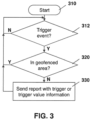
- FIG. 3 describes a process at a sensor apparatus, where such sensor apparatus could be one of many sensor apparatuses within a system.
- the process of Figure 3 starts at block 310 and proceeds to block 312 in which a check is made to determine whether a trigger condition has been met.
- a trigger condition For example, if the sensor apparatus is associated with a container, a door open or door closed event could be a trigger event. In other cases, if the container stops for a threshold period of time, this could be considered a trigger event. Further, if the sensor apparatus stops for a second period of time, where the second period of time is longer than the threshold, this could create a further trigger event indicating an extended stop.
- the trigger event could be a light level sensor within the container, a cabin overhead light within a cab of a vehicle turning on, and engine on or off event, connection to a certain network or access point, among other options.
- the process then proceeds to block 320 in which a check is made to determine whether the sensor apparatus is within a geofenced area. If the sensor apparatus is within the geofence area, then a new candidate geofenced area does not need to be created and the process therefore proceeds back to block 312 to look for further trigger events.
- the second report could simply provide the delta of the votes.
- the stopping between a first time period T1 and a second time period is worth two points or votes, and the stopping above the second time period T2 is worth four points or votes, then the second report at block 330 could simply include two points or votes as the delta from the first report to the second report.
- the process may then proceed to block 414 .
- the value received in the message of block 412, or derived from the trigger event received at block 412 is then added to a running sum of trigger values for the particular geographic location.
- the geographic coordinates that are provided within message 412 may be used to look up whether trigger events or votes have been previously received from the geographic region.
- the lookup uses a certain threshold distance from the reported geographic coordinates to find previous values. For example, a distance such as 50 meters from such location may be used in order to determine whether to add values to a running sum. If yes, then the trigger value that is received at, or derived from, message 412 is then added to the running sum in order to derive a total value for the location.
- the addition of the values at block 420 may depend on geographic boundaries. Thus, if a plurality of votes is received within an area, for example with a radius of 100 m, this may indicate that these values should be added together. If, however, a vote is received for an area that is outside of this region then the vote would not be counted for the geofenced area. Other options are possible.
- votes may have a time period for which they are valid. Thus, for example, if a vote was received more than six months ago, this may not be counted towards the threshold value, as the site is not visited often enough to create a geofenced area. In this case, the total value at block 420 would not include the stale votes.
- thresholds in the embodiments above can be configured by network operators. These include the value or points associated with each trigger condition, the threshold value used to create a candidate geofenced area, the threshold distance between the reporting areas which can be combined together, among other such data. Such thresholds could be set by the network operator in order to provide a system which meets such operator's needs.
- a server such as servers 240 , 242 or 250 may be any network node.
- servers 240 , 242 or 250 may be any network node.
- one simplified server that may perform the embodiments described above is provided with regards to Figure 6 .
- server 610 includes a processor 620 and a communications subsystem 630 , where the processor 620 and communications subsystem 630 cooperate to perform the methods of the embodiments described herein.
- Such computer-readable or machine-readable storage medium or media is (are) considered to be part of an article (or article of manufacture).
- An article or article of manufacture can refer to any manufactured single component or multiple components.
- the storage medium or media can be located either in the machine running the machine-readable instructions, or located at a remote site from which machine-readable instructions can be downloaded over a network for execution.
Claims (13)
- Procédé au niveau d'un élément de réseau pour créer un confinement géographique candidat, le procédé comprenant de :recevoir (412, 512) un message au niveau de l'élément de réseau, le message comprenant des coordonnées géographiques et une indication d'une valeur d'événement ;ajouter (414, 514) la valeur d'événement à une valeur courante pour une région géographique associée aux coordonnées géographiques, en créant une valeur totale,dans lequel la région géographique comprend une zone située à l'intérieur d'une distance seuil des coordonnées géographiques ;déterminer (420, 520) que la valeur totale dépasse un seuil ; etcréer (440, 540) le confinement géographique candidat étant la zone géographique ; etsignaler le confinement géographique candidat dans un rapport ou une alerte à un administrateur, afin de permettre de déterminer s'il faut ou non transformer le confinement géographique candidat en un confinement géographique actif pour signaler le moment où un appareil de capteur entre ou sort de la zone géographique.
- Procédé selon la revendication 1, dans lequel la valeur de l'événement est explicitement fournie dans le message.
- Procédé selon la revendication 1 ou 2, dans lequel la valeur d'événement est implicitement fournie dans le message en ayant une description d'événement dans le message et la valeur d'événement associée à la description d'événement mémorisée au niveau de l'élément de réseau.
- Procédé selon une quelconque des revendications précédentes, dans lequel la valeur d'événement est basée sur un événement déclencheur chez un expéditeur du message.
- Procédé selon la revendication 4, dans lequel l'expéditeur est associé à un conteneur ou à un véhicule, et dans lequel l'événement déclencheur est un des suivants : un événement d'ouverture de porte ; un événement de porte fermée ; un arrêt du conteneur ou du véhicule au moins une première fois ; un arrêt du conteneur ou du véhicule au moins une deuxième fois, la deuxième fois étant plus longue que la première fois ; un événement de démarrage du moteur ; un événement d'arrêt du moteur ; un événement de détection de lumière ; ou un événement d'éclairage de cabine.
- Procédé selon une quelconque des revendications précédentes, comprenant en outre de :
créer un rapport ou une alerte par l'élément de réseau concernant la création (440, 540) du confinement géographique candidat. - Procédé selon une quelconque des revendications précédentes, dans lequel la création (440, 540) du confinement géographique candidat comprend la création d'une forme pour le confinement géographique candidat, la forme incluant toutes les coordonnées géographiques reçues dans une distance seuil l'une de l'autre, dans lequel la forme est créée en ajoutant des valeurs d'événement correspondant aux coordonnées géographiques reçues.
- Elément de réseau configuré pour créer un confinement géographique candidat, l'élément de réseau comprenantun processeur (620) ; etun sous-système de communication (630), dans lequel l'élément de réseau est configuré pour :recevoir (412, 512) un message au niveau de l'élément de réseau, le message comprenant des coordonnées géographiques et une indication d'une valeur d'événement ;ajouter (414, 514) la valeur de l'événement à une valeur courante pour une région géographique associée aux coordonnées géographiques, créant une valeur totale, dans lequel la région géographique comprend une zone située à l'intérieur d'une distance seuil des coordonnées géographiques ;déterminer (420, 520) que la valeur totale dépasse un seuil ; etcréer (440, 540) le confinement géographique candidat étant la zone géographique ; etsignaler le confinement géographique candidat dans un rapport ou une alerte à un administrateur, afin de permettre de déterminer s'il faut ou non transformer le confinement géographique candidat en un confinement géographique actif pour signaler le moment où un appareil de capteur entre ou sort de la zone géographique.
- Elément de réseau selon la revendication 8, dans lequel la valeur de l'événement est explicitement fournie dans le message.
- Elément de réseau selon la revendication 8, dans lequel la valeur de l'événement est implicitement fournie dans le message en ayant une description d'événement dans le message et la valeur d'événement associée à la description d'événement mémorisée au niveau de l'élément de réseau.
- Elément de réseau selon la revendication 8, dans lequel l'élément de réseau est en outre configuré pour créer un rapport ou une alerte par l'élément de réseau concernant la création (440, 540) du confinement géographique candidat.
- Elément de réseau selon une quelconque des revendications 8 à 11, dans lequel l'élément de réseau est en outre configuré pour créer une forme pour le confinement géographique candidat, la forme incluant toutes les coordonnées géographiques reçues dans une distance seuil les unes des autres, dans lequel la forme est créée en ajoutant des valeurs d'événement correspondant aux coordonnées géographiques reçues.
- Support lisible par ordinateur pour mémoriser le code d'instruction pour créer un confinement géographique candidate qui, lorsqu'elles sont exécutées par un processeur (620) d'un élément de réseau (610), amènent l'élément de réseau (610) à exécuter le procédé d'une quelconque des revendications 1 à 7.
Applications Claiming Priority (1)
| Application Number | Priority Date | Filing Date | Title |
|---|---|---|---|
| US15/948,314 US10735894B2 (en) | 2018-04-09 | 2018-04-09 | Method and system for detection and creation of geofences |
Publications (4)
| Publication Number | Publication Date |
|---|---|
| EP3554104A1 EP3554104A1 (fr) | 2019-10-16 |
| EP3554104C0 EP3554104C0 (fr) | 2023-10-25 |
| EP3554104B1 true EP3554104B1 (fr) | 2023-10-25 |
| EP3554104B8 EP3554104B8 (fr) | 2023-12-06 |
Family
ID=66102869
Family Applications (1)
| Application Number | Title | Priority Date | Filing Date |
|---|---|---|---|
| EP19167606.3A Active EP3554104B8 (fr) | 2018-04-09 | 2019-04-05 | Procédé et système de détection et de création de périmètres virtuels |
Country Status (3)
| Country | Link |
|---|---|
| US (1) | US10735894B2 (fr) |
| EP (1) | EP3554104B8 (fr) |
| ES (1) | ES2965613T3 (fr) |
Families Citing this family (2)
| Publication number | Priority date | Publication date | Assignee | Title |
|---|---|---|---|---|
| US11659427B2 (en) * | 2020-04-27 | 2023-05-23 | Spirent Communications, Inc. | Efficient real-time 802.11ax OFDMA statistics logging |
| CN111640276B (zh) * | 2020-05-15 | 2021-10-22 | 珠海格力电器股份有限公司 | 基于电子围栏的预警方法及装置、系统 |
Family Cites Families (8)
| Publication number | Priority date | Publication date | Assignee | Title |
|---|---|---|---|---|
| US8018329B2 (en) | 2008-12-12 | 2011-09-13 | Gordon * Howard Associates, Inc. | Automated geo-fence boundary configuration and activation |
| US20140258201A1 (en) | 2013-03-05 | 2014-09-11 | Qualcomm Incorporated | Generating a geofence via an analysis of a gps fix utilization distribution |
| US9414193B2 (en) | 2013-07-17 | 2016-08-09 | Qualcomm Incorporated | Communicating RF fingerprint-based geofences |
| US9313616B2 (en) | 2013-09-16 | 2016-04-12 | Fleetmatics Development Limited | System and method for automated identification of location types for geofences |
| US9306608B2 (en) * | 2013-11-05 | 2016-04-05 | Ford Global Technologies, Llc | Method and apparatus for vehicle radio station privacy mode control |
| US10163132B2 (en) * | 2014-02-19 | 2018-12-25 | Ebay Inc. | Systems and methods to create a geographic heatmap |
| US9307361B2 (en) | 2014-03-24 | 2016-04-05 | Zos Communications, Llc | Start and stop moving notification triggers for location based tracking |
| US10228258B2 (en) * | 2014-12-03 | 2019-03-12 | Strava, Inc. | Determining top venues from aggregated user activity location data |
-
2018
- 2018-04-09 US US15/948,314 patent/US10735894B2/en active Active
-
2019
- 2019-04-05 EP EP19167606.3A patent/EP3554104B8/fr active Active
- 2019-04-05 ES ES19167606T patent/ES2965613T3/es active Active
Also Published As
| Publication number | Publication date |
|---|---|
| EP3554104C0 (fr) | 2023-10-25 |
| ES2965613T3 (es) | 2024-04-16 |
| EP3554104B8 (fr) | 2023-12-06 |
| EP3554104A1 (fr) | 2019-10-16 |
| US10735894B2 (en) | 2020-08-04 |
| US20190313205A1 (en) | 2019-10-10 |
Similar Documents
| Publication | Publication Date | Title |
|---|---|---|
| EP3554105A1 (fr) | Procédé et système de génération de forme de barrière géographique | |
| EP3588143B1 (fr) | Procédé et système de suivi d'actifs | |
| US10356577B1 (en) | Method and system for asset tracking | |
| US11521155B2 (en) | Method and system for detecting duration and cause of border delays | |
| US11868949B2 (en) | Method and system for internet of things asset tracking within an intelligent transportation system | |
| US20230217140A1 (en) | Method and system for moving status detection for a sensor apparatus | |
| EP3554104B1 (fr) | Procédé et système de détection et de création de périmètres virtuels | |
| US10949680B2 (en) | Method and system for rear status detection | |
| EP3624031A1 (fr) | Procédé et système de gestion en commun d'actifs de transport | |
| CN114966752A (zh) | 用于装运货物跟踪的方法、设备和系统 | |
| US11310322B2 (en) | Method and system for pairing a chassis and container in an asset tracking system | |
| US11288624B2 (en) | Method and system for yard asset management | |
| EP3624030B1 (fr) | Procédé et système de location d'actifs en vrac |
Legal Events
| Date | Code | Title | Description |
|---|---|---|---|
| PUAI | Public reference made under article 153(3) epc to a published international application that has entered the european phase |
Free format text: ORIGINAL CODE: 0009012 |
|
| STAA | Information on the status of an ep patent application or granted ep patent |
Free format text: STATUS: THE APPLICATION HAS BEEN PUBLISHED |
|
| AK | Designated contracting states |
Kind code of ref document: A1 Designated state(s): AL AT BE BG CH CY CZ DE DK EE ES FI FR GB GR HR HU IE IS IT LI LT LU LV MC MK MT NL NO PL PT RO RS SE SI SK SM TR |
|
| AX | Request for extension of the european patent |
Extension state: BA ME |
|
| STAA | Information on the status of an ep patent application or granted ep patent |
Free format text: STATUS: REQUEST FOR EXAMINATION WAS MADE |
|
| 17P | Request for examination filed |
Effective date: 20200415 |
|
| RBV | Designated contracting states (corrected) |
Designated state(s): AL AT BE BG CH CY CZ DE DK EE ES FI FR GB GR HR HU IE IS IT LI LT LU LV MC MK MT NL NO PL PT RO RS SE SI SK SM TR |
|
| STAA | Information on the status of an ep patent application or granted ep patent |
Free format text: STATUS: EXAMINATION IS IN PROGRESS |
|
| 17Q | First examination report despatched |
Effective date: 20210610 |
|
| GRAP | Despatch of communication of intention to grant a patent |
Free format text: ORIGINAL CODE: EPIDOSNIGR1 |
|
| STAA | Information on the status of an ep patent application or granted ep patent |
Free format text: STATUS: GRANT OF PATENT IS INTENDED |
|
| INTG | Intention to grant announced |
Effective date: 20220706 |
|
| GRAJ | Information related to disapproval of communication of intention to grant by the applicant or resumption of examination proceedings by the epo deleted |
Free format text: ORIGINAL CODE: EPIDOSDIGR1 |
|
| STAA | Information on the status of an ep patent application or granted ep patent |
Free format text: STATUS: EXAMINATION IS IN PROGRESS |
|
| GRAP | Despatch of communication of intention to grant a patent |
Free format text: ORIGINAL CODE: EPIDOSNIGR1 |
|
| INTC | Intention to grant announced (deleted) | ||
| STAA | Information on the status of an ep patent application or granted ep patent |
Free format text: STATUS: GRANT OF PATENT IS INTENDED |
|
| INTG | Intention to grant announced |
Effective date: 20221215 |
|
| GRAJ | Information related to disapproval of communication of intention to grant by the applicant or resumption of examination proceedings by the epo deleted |
Free format text: ORIGINAL CODE: EPIDOSDIGR1 |
|
| STAA | Information on the status of an ep patent application or granted ep patent |
Free format text: STATUS: EXAMINATION IS IN PROGRESS |
|
| INTC | Intention to grant announced (deleted) | ||
| GRAP | Despatch of communication of intention to grant a patent |
Free format text: ORIGINAL CODE: EPIDOSNIGR1 |
|
| STAA | Information on the status of an ep patent application or granted ep patent |
Free format text: STATUS: GRANT OF PATENT IS INTENDED |
|
| INTG | Intention to grant announced |
Effective date: 20230525 |
|
| GRAS | Grant fee paid |
Free format text: ORIGINAL CODE: EPIDOSNIGR3 |
|
| GRAA | (expected) grant |
Free format text: ORIGINAL CODE: 0009210 |
|
| STAA | Information on the status of an ep patent application or granted ep patent |
Free format text: STATUS: THE PATENT HAS BEEN GRANTED |
|
| AK | Designated contracting states |
Kind code of ref document: B1 Designated state(s): AL AT BE BG CH CY CZ DE DK EE ES FI FR GB GR HR HU IE IS IT LI LT LU LV MC MK MT NL NO PL PT RO RS SE SI SK SM TR |
|
| REG | Reference to a national code |
Ref country code: GB Ref legal event code: FG4D |
|
| REG | Reference to a national code |
Ref country code: CH Ref legal event code: EP |
|
| REG | Reference to a national code |
Ref country code: CH Ref legal event code: PK Free format text: BERICHTIGUNG B8 |
|
| REG | Reference to a national code |
Ref country code: DE Ref legal event code: R096 Ref document number: 602019039903 Country of ref document: DE |
|
| REG | Reference to a national code |
Ref country code: IE Ref legal event code: FG4D |
|
| RAP2 | Party data changed (patent owner data changed or rights of a patent transferred) |
Owner name: MALIKIE INNOVATIONS LIMITED |
|
| U01 | Request for unitary effect filed |
Effective date: 20231114 |
|
| U07 | Unitary effect registered |
Designated state(s): AT BE BG DE DK EE FI FR IT LT LU LV MT NL PT SE SI Effective date: 20231120 |
|
| PG25 | Lapsed in a contracting state [announced via postgrant information from national office to epo] |
Ref country code: GR Free format text: LAPSE BECAUSE OF FAILURE TO SUBMIT A TRANSLATION OF THE DESCRIPTION OR TO PAY THE FEE WITHIN THE PRESCRIBED TIME-LIMIT Effective date: 20240126 |
|
| PG25 | Lapsed in a contracting state [announced via postgrant information from national office to epo] |
Ref country code: IS Free format text: LAPSE BECAUSE OF FAILURE TO SUBMIT A TRANSLATION OF THE DESCRIPTION OR TO PAY THE FEE WITHIN THE PRESCRIBED TIME-LIMIT Effective date: 20240225 |
|
| REG | Reference to a national code |
Ref country code: ES Ref legal event code: FG2A Ref document number: 2965613 Country of ref document: ES Kind code of ref document: T3 Effective date: 20240416 |
|
| PG25 | Lapsed in a contracting state [announced via postgrant information from national office to epo] |
Ref country code: IS Free format text: LAPSE BECAUSE OF FAILURE TO SUBMIT A TRANSLATION OF THE DESCRIPTION OR TO PAY THE FEE WITHIN THE PRESCRIBED TIME-LIMIT Effective date: 20240225 Ref country code: GR Free format text: LAPSE BECAUSE OF FAILURE TO SUBMIT A TRANSLATION OF THE DESCRIPTION OR TO PAY THE FEE WITHIN THE PRESCRIBED TIME-LIMIT Effective date: 20240126 |