EP3554027A1 - Drahtloskommunikationsbasisstationsvorrichtung und divisionsnummernbestimmungsverfahren - Google Patents
Drahtloskommunikationsbasisstationsvorrichtung und divisionsnummernbestimmungsverfahren Download PDFInfo
- Publication number
- EP3554027A1 EP3554027A1 EP19178865.2A EP19178865A EP3554027A1 EP 3554027 A1 EP3554027 A1 EP 3554027A1 EP 19178865 A EP19178865 A EP 19178865A EP 3554027 A1 EP3554027 A1 EP 3554027A1
- Authority
- EP
- European Patent Office
- Prior art keywords
- section
- transmission
- layers
- bandwidth
- terminal
- Prior art date
- Legal status (The legal status is an assumption and is not a legal conclusion. Google has not performed a legal analysis and makes no representation as to the accuracy of the status listed.)
- Granted
Links
Images


Classifications
-
- H—ELECTRICITY
- H04—ELECTRIC COMMUNICATION TECHNIQUE
- H04B—TRANSMISSION
- H04B7/00—Radio transmission systems, i.e. using radiation field
- H04B7/02—Diversity systems; Multi-antenna system, i.e. transmission or reception using multiple antennas
- H04B7/12—Frequency diversity
-
- H—ELECTRICITY
- H04—ELECTRIC COMMUNICATION TECHNIQUE
- H04L—TRANSMISSION OF DIGITAL INFORMATION, e.g. TELEGRAPHIC COMMUNICATION
- H04L27/00—Modulated-carrier systems
- H04L27/26—Systems using multi-frequency codes
- H04L27/2601—Multicarrier modulation systems
- H04L27/2602—Signal structure
-
- H—ELECTRICITY
- H04—ELECTRIC COMMUNICATION TECHNIQUE
- H04B—TRANSMISSION
- H04B7/00—Radio transmission systems, i.e. using radiation field
- H04B7/02—Diversity systems; Multi-antenna system, i.e. transmission or reception using multiple antennas
- H04B7/04—Diversity systems; Multi-antenna system, i.e. transmission or reception using multiple antennas using two or more spaced independent antennas
- H04B7/0413—MIMO systems
-
- H—ELECTRICITY
- H04—ELECTRIC COMMUNICATION TECHNIQUE
- H04L—TRANSMISSION OF DIGITAL INFORMATION, e.g. TELEGRAPHIC COMMUNICATION
- H04L1/00—Arrangements for detecting or preventing errors in the information received
- H04L1/004—Arrangements for detecting or preventing errors in the information received by using forward error control
- H04L1/0041—Arrangements at the transmitter end
- H04L1/0042—Encoding specially adapted to other signal generation operation, e.g. in order to reduce transmit distortions, jitter, or to improve signal shape
-
- H—ELECTRICITY
- H04—ELECTRIC COMMUNICATION TECHNIQUE
- H04L—TRANSMISSION OF DIGITAL INFORMATION, e.g. TELEGRAPHIC COMMUNICATION
- H04L25/00—Baseband systems
- H04L25/02—Details ; arrangements for supplying electrical power along data transmission lines
- H04L25/0202—Channel estimation
- H04L25/0224—Channel estimation using sounding signals
- H04L25/0226—Channel estimation using sounding signals sounding signals per se
-
- H—ELECTRICITY
- H04—ELECTRIC COMMUNICATION TECHNIQUE
- H04L—TRANSMISSION OF DIGITAL INFORMATION, e.g. TELEGRAPHIC COMMUNICATION
- H04L27/00—Modulated-carrier systems
- H04L27/26—Systems using multi-frequency codes
- H04L27/2601—Multicarrier modulation systems
- H04L27/2626—Arrangements specific to the transmitter only
- H04L27/2627—Modulators
- H04L27/2634—Inverse fast Fourier transform [IFFT] or inverse discrete Fourier transform [IDFT] modulators in combination with other circuits for modulation
- H04L27/2636—Inverse fast Fourier transform [IFFT] or inverse discrete Fourier transform [IDFT] modulators in combination with other circuits for modulation with FFT or DFT modulators, e.g. standard single-carrier frequency-division multiple access [SC-FDMA] transmitter or DFT spread orthogonal frequency division multiplexing [DFT-SOFDM]
-
- H—ELECTRICITY
- H04—ELECTRIC COMMUNICATION TECHNIQUE
- H04L—TRANSMISSION OF DIGITAL INFORMATION, e.g. TELEGRAPHIC COMMUNICATION
- H04L5/00—Arrangements affording multiple use of the transmission path
- H04L5/003—Arrangements for allocating sub-channels of the transmission path
- H04L5/0037—Inter-user or inter-terminal allocation
- H04L5/0039—Frequency-contiguous, i.e. with no allocation of frequencies for one user or terminal between the frequencies allocated to another
-
- H—ELECTRICITY
- H04—ELECTRIC COMMUNICATION TECHNIQUE
- H04L—TRANSMISSION OF DIGITAL INFORMATION, e.g. TELEGRAPHIC COMMUNICATION
- H04L5/00—Arrangements affording multiple use of the transmission path
- H04L5/003—Arrangements for allocating sub-channels of the transmission path
- H04L5/0048—Allocation of pilot signals, i.e. of signals known to the receiver
-
- H—ELECTRICITY
- H04—ELECTRIC COMMUNICATION TECHNIQUE
- H04W—WIRELESS COMMUNICATION NETWORKS
- H04W72/00—Local resource management
- H04W72/04—Wireless resource allocation
- H04W72/044—Wireless resource allocation based on the type of the allocated resource
- H04W72/0453—Resources in frequency domain, e.g. a carrier in FDMA
-
- H—ELECTRICITY
- H04—ELECTRIC COMMUNICATION TECHNIQUE
- H04L—TRANSMISSION OF DIGITAL INFORMATION, e.g. TELEGRAPHIC COMMUNICATION
- H04L1/00—Arrangements for detecting or preventing errors in the information received
- H04L1/004—Arrangements for detecting or preventing errors in the information received by using forward error control
- H04L1/0056—Systems characterized by the type of code used
- H04L1/0061—Error detection codes
-
- H—ELECTRICITY
- H04—ELECTRIC COMMUNICATION TECHNIQUE
- H04L—TRANSMISSION OF DIGITAL INFORMATION, e.g. TELEGRAPHIC COMMUNICATION
- H04L25/00—Baseband systems
- H04L25/02—Details ; arrangements for supplying electrical power along data transmission lines
- H04L25/03—Shaping networks in transmitter or receiver, e.g. adaptive shaping networks
- H04L25/03006—Arrangements for removing intersymbol interference
- H04L25/03159—Arrangements for removing intersymbol interference operating in the frequency domain
-
- H—ELECTRICITY
- H04—ELECTRIC COMMUNICATION TECHNIQUE
- H04L—TRANSMISSION OF DIGITAL INFORMATION, e.g. TELEGRAPHIC COMMUNICATION
- H04L5/00—Arrangements affording multiple use of the transmission path
- H04L5/0001—Arrangements for dividing the transmission path
- H04L5/0014—Three-dimensional division
- H04L5/0023—Time-frequency-space
Definitions
- the present invention relates to a radio communication base station apparatus and division number decision method.
- SC transmission a transmission signal is transmitted using consecutive frequency bands. Therefore, in SC transmission, channel correlation between frequency bands to which a transmission signal is mapped is high, and furthermore, transmission power can be concentrated in consecutive frequency bands. Consequently, by filtering a channel estimate estimated based on a pilot signal, a significant noise averaging effect can be obtained, and satisfactory channel estimation accuracy is obtained.
- a transmission signal is transmitted using nonconsecutive frequency bands. Therefore, in MC transmission, a transmission signal can be assigned to a wider frequency band than in the case of SC transmission, enabling a greater frequency diversity effect to be obtained than with SC transmission.
- DFT-s-OFDM Discrete Fourier Transform spread Orthogonal Frequency Division Multiplexing
- SDC Spectrum Division Control
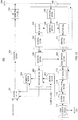
- FIG.1 is a block diagram showing an outline configuration of a DFT-s-OFDM with SDC type of radio communication terminal apparatus (hereinafter referred to as "terminal").
- a terminal performs DFT processing on a data signal, and adds a CP (Cyclic Prefix) before transmission.
- switching between SC transmission and MC transmission can be performed by having the subcarrier mapping section shown in FIG.1 control the method of mapping a data signal in the frequency domain.
- SC transmission is used if the number of data divisions in the frequency domain (hereinafter referred to as the number of SD's (Spectrum Divisions)) is 1, and MC transmission is used if the number of SD's is 2 or more.
- a radio communication base station apparatus (hereinafter referred to as “base station”) can switch adaptively between SC transmission and MC transmission by controlling the number of SD's according to the communication environment of a terminal.
- DFT-s-OFDM with SDC is that the CM (Cubic Metric) or PAPR (Peak-to-Average Power Ratio) in MC transmission can be lowered compared with OFDMA (Orthogonal Frequency Division Multiple Access).
- CM Cubic Metric
- PAPR Peak-to-Average Power Ratio
- OFDMA Orthogonal Frequency Division Multiple Access
- NPL 1 NEC R1-081752, "Proposals on PHY related aspects in LTE Advanced," 3GPP TSG RANI #53, Kansas City, MO, USA, 5-9 May, 2008
- a data signal and pilot signal are time-multiplexed in a transmission signal transmitted from a terminal.
- a block that includes a pilot signal is called a pilot block. That is to say, a transmission signal includes one or a plurality of pilot blocks.
- a terminal divides the plurality of pilot blocks included in a transmission signal, and generates a plurality of pilot block groups.
- a group of pilot blocks is called a cluster, for example. For instance, a terminal may generate two clusters each comprising a group of three pilot blocks by dividing six pilot blocks included in a transmission signal into two.
- a coherent bandwidth which is a bandwidth in which there is mutual correlation with a signal propagation characteristic
- the larger the number of pilot blocks the greater is the noise averaging effect of filtering, and therefore the higher is the channel estimation accuracy obtained.
- the larger the number of SD's the more finely a transmission signal is divided and the smaller is the number of pilot blocks composing each cluster, and thus the smaller is the number of pilot blocks mapped within the coherent bandwidth. Consequently, only a small noise averaging effect is obtained, and channel estimation accuracy declines.
- the smaller the number of SD's the larger is the number of pilot blocks composing each cluster, and thus the larger is the number of pilot blocks mapped within the coherent bandwidth.
- the smaller the number of SD's the smaller is the number of clusters generated by division, and thus pilot blocks can no longer be mapped over a wide bandwidth, and the frequency diversity effect decreases.
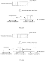
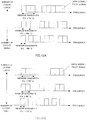
- a terminal transmits a transmission signal composed of six pilot blocks (for example, pilot blocks of six subcarriers).
- the number of SD's is 2, and therefore the terminal divides the six pilot blocks into two, and performs mapping to a frequency band with three pilot blocks (pilot blocks of three subcarriers) as one cluster.
- the number of SD's is 3, and therefore the terminal divides the six pilot blocks into three, and performs mapping to a frequency band with two pilot blocks (pilot blocks of two subcarriers) as one cluster.
- pilot blocks included in one cluster are mapped within a coherent bandwidth. Assuming that mutually different clusters are mapped separated by frequency interval ⁇ wider than a coherent bandwidth, signal propagation characteristic correlation between pilot blocks included in different clusters is low.
- FIG.2A number of SD's: 2
- FIG.2B number of SD's: 3
- channel estimation is performed using fewer pilot blocks than in FIG.2A (number of SD's: 2), and therefore channel estimation accuracy is lower than in FIG.2A (number of SD's: 2).
- FIG.2A two clusters generated by dividing a transmission signal into two are arranged in a distributed fashion in the frequency domain
- FIG.2B three clusters generated by dividing a transmission signal into three are arranged in a distributed fashion in the frequency domain. That is to say, in FIG.2A (number of SD's: 2), the number of SD's is smaller than in FIG.2B (number of SD's: 3), and therefore the frequency diversity effect is smaller than in FIG.2B (number of SD's: 3).
- a radio communication base station apparatus of the present invention employs a configuration having a decision section that decides the number of divisions in the frequency domain of a transmission signal from a radio communication terminal apparatus, and a scheduling section that schedules allocation to a frequency resource of the transmission signal that is divided into the number of divisions; wherein the decision section increases the number of divisions in proportion to the number of pilot blocks included in the transmission signal.
- a division number decision method of the present invention decides the number of divisions in the frequency domain of a transmission signal from a radio communication terminal apparatus, and provides for the number of divisions to be increased in proportion to the number of pilot blocks included in the transmission signal.
- the present invention enables a frequency diversity effect to be improved while maintaining channel estimation accuracy, regardless of the number of SD's.
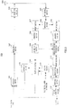
- base station 100 The configuration of base station 100 according to this embodiment will now be described using FIG.3 .
- encoding section 101 of base station 100 shown in FIG.3 transmission data (downlink data), a response signal (ACK signal or NACK signal) from error detection section 116, "Grant” indicating resource allocation information of each terminal from scheduling section 118, and division information indicating a transmission signal division pattern of each terminal from generation section 119.
- Control information comprises a response signal, "Grant,” and division information.
- Encoding section 101 encodes the transmission data and control information, and outputs encoded data to modulation section 102.
- Modulation section 102 modulates encoded data input from encoding section 101, and outputs a post-modulation signal to RF transmitting section 103.
- RF transmitting section 103 executes transmission processing such as D/A conversion, up-conversion, and amplification on a signal input from modulation section 102, and performs radio transmission of a signal on which transmission processing has been executed to each terminal from antenna 104.
- RF receiving section 105 executes reception processing such as down-conversion and A/D conversion on a signal from each terminal received via antenna 104, and outputs a signal on which reception processing has been executed to separation section 106.
- Separation section 106 separates a signal input from RF receiving section 105 into a pilot signal and data signal. Then separation section 106 outputs a pilot signal to DFT section 107, and outputs a data signal to DFT section 110.
- DFT section 107 executes DFT processing on a pilot signal input from separation section 106, and converts the signal from a time-domain signal to a frequency-domain signal. Then DFT section 107 outputs a pilot signal that has been converted to the frequency domain to demapping section 108.
- Demapping section 108 extracts from a frequency-domain pilot signal input from DFT section 107 a pilot signal of a part corresponding to a transmission band of each terminal. Then demapping section 108 outputs each extracted pilot signal to estimation section 109.
- estimation section 109 Based on a pilot signal input from demapping section 108, estimation section 109 estimates a channel frequency fluctuation (channel frequency response) estimate and reception quality estimate. Then estimation section 109 outputs a channel frequency fluctuation estimate to frequency domain equalization section 112, and outputs a reception quality estimate to scheduling section 118.
- DFT section 110 executes DFT processing on a data signal input from separation section 106, and converts the signal from a time-domain signal to a frequency-domain signal. Then DFT section 110 outputs a data signal that has been converted to the frequency domain to demapping section 111.
- Demapping section 111 extracts from a signal input from DFT section 110 a data signal of a part corresponding to a transmission band of each terminal. Then demapping section 111 outputs each extracted signal to frequency domain equalization section 112.
- Frequency domain equalization section 112 executes equalization processing on a data signal input from demapping section 111 using a channel frequency fluctuation estimate input from estimation section 109. Then frequency domain equalization section 112 outputs a signal on which equalization processing has been executed to IFFT section 113.
- IFFT section 113 executes IFFT processing on a data signal input from frequency domain equalization section 112. Then IFFT section 113 outputs a signal on which IFFT processing has been executed to demodulation section 114.
- Demodulation section 114 executes demodulation processing on a signal input from IFFT section 113, and outputs a signal on which demodulation processing has been executed to decoding section 115.
- Decoding section 115 executes decoding processing on a signal input from demodulation section 114, and outputs a signal on which decoding processing has been executed (a decoded bit string) to error detection section 116.
- Error detection section 116 performs error detection on a decoded bit string input from decoding section 115. Error detection section 116 performs error detection using a CRC, for example. Error detection section 116 generates a NACK signal as a response signal if the error detection result is that there is an error in the decoded bits, or generates an ACK signal as a response signal if the error detection result is that there is no error in the decoded bits. Then error detection section 116 outputs the generated response signal to encoding section 101. If there is no error in the decoded bits, error detection section 116 also outputs a data signal as received data.
- Pilot block number information indicating the number of pilot blocks in a terminal's transmission signal is input to decision section 117 and scheduling section 118.
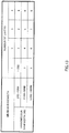
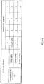
- decision section 117 stores beforehand a plurality of division patterns (in FIG.4 , division pattern A, division pattern B, and division pattern C) for each of which the association between the number of pilot blocks and the number of SD's is different. Based on the number of pilot blocks indicated by input pilot block number information, decision section 117 decides the number of SD's that is the number of divisions in the frequency domain of a transmission signal from a terminal, using one of the plurality of division patterns. Here, for example, decision section 117 uses one of the plurality of division patterns based on the reception quality of a radio channel between decision section 117's base station and a terminal (here, terminal 200). Also, the larger the number of pilot blocks included in a transmission signal, the larger decision section 117 makes the number of SD's. Then decision section 117 outputs SD number information indicating the decided number of SD's to scheduling section 118.
- division patterns in FIG.4 , division pattern A, division pattern B, and division pattern C
- Scheduling section 118 schedules allocation of a transmission signal transmitted from each terminal to a transmission band (frequency resource) in accordance with a reception quality estimate input from estimation section 109 and SD number information input from decision section 117. For example, based on a reception quality estimate, scheduling section 118 schedules a transmission signal divided into the number of SD's indicated by the SD number information (a transmission signal comprising the number of pilot blocks indicated by the pilot block number information) to a frequency resource. Then scheduling section 118 outputs "Grant" indicating the scheduling result (for example, the start position and bandwidth of a frequency resource to which the transmission signal is allocated) to encoding section 101, and outputs SD number information and pilot block number information to generation section 119.
- generation section 119 stores beforehand the plurality of division patterns shown in FIG.4 . Based on the number of SD's indicated by SD number information input from scheduling section 118, and the number of pilot blocks indicated by pilot block number information, generation section 119 identifies a division pattern used by decision section 117, and generates division information indicating the identified division pattern. Then generation section 119 outputs the generated division information to encoding section 101. By this means, a division pattern is reported to each terminal. In base station 100, a division pattern selected by decision section 117 may be output to generation section 119, and generation section 119 may use the division pattern input from decision section 117 to generate division information indicating the division pattern.
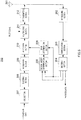
- terminal 200 Next, the configuration of terminal 200 according to this embodiment will be described using FIG.5 .
- RF receiving section 202 of terminal 200 shown in FIG.5 executes reception processing such as down-conversion and A/D conversion on a signal received from base station 100 via antenna 201, and outputs a signal on which reception processing has been executed to demodulation section 203.
- Demodulation section 203 executes equalization processing and demodulation processing on a signal input from RF receiving section 202, and outputs a signal on which this processing has been executed to decoding section 204.
- Decoding section 204 executes decoding processing on a signal input from demodulation section 203, and extracts received data and control information.
- a response signal (ACK signal or NACK signal), "Grant,” and division information are included in the control information.
- decoding section 204 outputs "Grant" to division number determination section 205 and band determination section 206, and outputs division information to division number determination section 205.
- Division number determination section 205 stores beforehand the same plurality of division patterns ( FIG.4 ) as generation section 119 of base station 100.
- Division number determination section 205 determines the number of SD's of a transmission signal of this terminal based on "Grant" and division information input from decoding section 204. For example, of the plurality of division patterns shown in FIG.4 , division number determination section 205 determines a division pattern indicated by division information, and the number of SD's corresponding to the frequency bandwidth (that is, the number of pilot blocks) of a transmission signal of this terminal requested by "Grant.” Then division number determination section 205 outputs the determined number of SD's to band determination section 206.
- Band determination section 206 determines a frequency resource to which a transmission signal of this terminal is to be allocated based on "Grant" input from decoding section 204 and the number of SD's input from division number determination section 205. Then band determination section 206 outputs band information indicating the determined frequency resource to allocation section 210.
- CRC section 207 performs CRC encoding on transmission data and generates CRC encoded data, and outputs the generated CRC encoded data to encoding section 208.
- Encoding section 208 encodes CRC encoded data input from CRC section 207, and outputs encoded data to modulation section 209.
- Modulation section 209 modulates encoded data input from encoding section 208, and outputs a post-modulation data signal to allocation section 210.
- Allocation section 210 allocates a data signal input from modulation section 209 to a frequency resource (RB) based on band information input from band determination section 206. Allocation section 210 outputs a data signal allocated to an RB to multiplexing section 211.
- RB frequency resource
- Multiplexing section 211 performs time multiplexing of a pilot signal and the data signal input from allocation section 210, and outputs a multiplex signal to RF transmitting section 212.
- a transmission signal comprising a pilot block composed of a data signal and pilot signal is generated.
- RF transmitting section 212 executes transmission processing such as D/A conversion, up-conversion, and amplification on a multiplex signal input from multiplexing section 211, and performs radio transmission of a signal on which transmission processing has been executed from antenna 201 to base station 100.
- pilot blocks or more it is necessary for a certain number of pilot blocks or more to be mapped within a coherent bandwidth, even when a transmission signal is divided.
- the number of pilot blocks necessary to obtain satisfactory channel estimation accuracy within a coherent bandwidth is three or more.
- three pilot blocks should be included in each cluster generated by dividing the transmission signal. That is to say, a minimum of the number of pilot blocks with which satisfactory channel estimation accuracy is obtained within a coherent bandwidth should be mapped.
- the number of SD's should be decided so that a cluster comprises a minimum of three pilot blocks (that is, the number of pilot blocks with which satisfactory channel estimation accuracy is obtained).
- the total number of pilot blocks included in a transmission signal is the number of pilot blocks per cluster generated by dividing a transmission signal (here, three) ⁇ the number of SD's.
- the number of pilot blocks per cluster is fixed, the number of SD's increases in proportion to the total number of pilot blocks.
- a certain number here, three
- channel estimation accuracy can be maintained even when the number of SD's increases in proportion to the number of pilot blocks included in a transmission signal.
- the larger the number of SD's the more the frequency diversity effect can be improved, since a plurality of clusters can be arranged in a distributed fashion in a wide band.
- the larger decision section 117 makes the number of SD's.
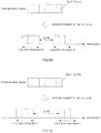
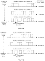
- numbers of pilot blocks are classified into three categories: small, medium, and large. Specifically, as shown in FIG.4 and FIG.6 , a case in which the number of pilot blocks is six or less is categorized as "number of pilot blocks: small,” a case in which the number of pilot blocks is between seven and nine is categorized as “number of pilot blocks: medium,” and a case in which the number of pilot blocks is more than nine is categorized as "number of pilot blocks: large.” Also, as shown in FIG.6 , a frequency interval between clusters is denoted by any one of ⁇ 1, ⁇ 2, or ⁇ 3.
- ⁇ 1, ⁇ 2, and ⁇ 3 are all values greater than the coherent bandwidth, and ⁇ 1, ⁇ 2, and ⁇ 3 may all be the same value, for example.
- the number of SD's is 1 whatever the number of pilot blocks. That is to say, SC transmission with no division of a transmission signal is performed.
- MC transmission is performed.
- Division pattern B shown in FIG.4 will now be described.
- the larger the number of pilot blocks indicated by input pilot block number information the larger decision section 117 makes the number of SD's. For example, when the number of pilot blocks is 6 (that is, in the "number of pilot blocks: small” case), decision section 117 decides the number of pilot blocks to be 2, as shown in FIG.4 . Similarly, when the number of pilot blocks is 9 (that is, in the "number of pilot blocks: medium” case), decision section 117 decides the number of pilot blocks to be 3, as shown in FIG.4 . And when the number of pilot blocks is 12 (that is, in the "number of pilot blocks: large” case), decision section 117 decides the number of pilot blocks to be 4, as shown in FIG.4 .
- scheduling section 118 allocates a transmission signal divided into two (two clusters) in the frequency domain separated by ⁇ 1, as shown at the top of FIG.6 .
- the number of pilot blocks is 9 (that is, in the "number of pilot blocks: medium” case)
- scheduling section 118 allocates a transmission signal divided into three (three clusters) in the frequency domain separated by ⁇ 1 and ⁇ 2 respectively, as shown in the middle of FIG.6 .
- scheduling section 118 allocates a transmission signal divided into four (four clusters) in the frequency domain separated by ⁇ 1, ⁇ 2, and A3 respectively, as shown at the bottom of FIG.6 .
- the larger decision section 117 makes the number of SD's.
- channel estimation accuracy can be maintained regardless of whether the number of pilot blocks included in a transmission signal is "large,” “medium,” or “small,” as shown in FIG.6 , and, since a transmission signal is divided at three-pilot-block intervals, regardless of the number of pilot blocks included in a transmission signal.
- the present invention is not limited to a transmission signal being divided at three-pilot-block intervals -- that is, to the number of pilot blocks included in each cluster being made three. Also, in the present invention, the number of pilot blocks included in each cluster may be made to differ.
- division pattern C shown in FIG.4
- the larger decision section 117 makes the number of SD's, in the same way as with division pattern B.
- the number of SD's in the same number of pilot blocks is larger in division pattern C than in division pattern B.
- the numbers of SD's corresponding to "small,” “medium,” and “large” numbers of pilot blocks respectively are 3, 4, and 5 in division pattern C as opposed to 2, 3, and 4 in division pattern B.
- base station 100 and terminal 200 use three division patterns -- division pattern A, division pattern B, and division pattern C -- but the number of division patterns used in the present invention is not limited to three.
- base station 100 and terminal 200 may use only two division patterns -- division pattern A and division pattern B -- or may use four division patterns -- division pattern A, division pattern B, division pattern C, and division pattern D.
- Reception quality between base station 100 and terminal 200 changes according to frequency-domain channel fluctuation caused by delay spread or a Doppler frequency, for instance.
- frequency-domain channel fluctuation is mild, good reception quality can be obtained over a wide range of consecutive frequency bands (that is, the coherent bandwidth is wide).
- frequency-domain channel fluctuation is severe, good reception quality cannot be obtained over a wide range of consecutive frequency bands (that is, the coherent bandwidth is narrow). Therefore, it is desirable for different numbers of SD's to be decided upon according to channel fluctuation between base station 100 and terminal 200. Specifically, the more severe the frequency-domain channel fluctuation (the narrower the coherent bandwidth), the narrower is the continuous frequency band in which good reception quality can be obtained, and therefore the larger the number of SD's should be made.
- decision section 117 uses one or another of division pattern A, division pattern B, and division pattern C shown in FIG.4 according to channel fluctuation between base station 100 and terminal 200.
- decision section 117 sets threshold value 1 and threshold value 2 (where threshold value 1 ⁇ threshold value 2), for example, beforehand. Then, for example, decision section 117 decides the number of SD's using division pattern A shown in FIG.4 if the delay spread is less than threshold value 1 (if channel fluctuation is mild), decides the number of SD's using division pattern B shown in FIG.4 if the delay spread is greater than or equal to threshold value 1 but less than threshold value 2, or decides the number of SD's using division pattern C shown in FIG.4 if the delay spread is greater than or equal to threshold value 2 (if channel fluctuation is severe).
- base station 100 can allocate pilot blocks to a wide range of consecutive frequency bands (coherent bandwidth) with good reception quality by deciding the number of SD's to be 1. Also, when channel fluctuation is severe (when the delay spread is greater than or equal to threshold value 2), good reception quality can only be obtained in a narrow consecutive frequency band range. Thus, by making the number of SD's larger, base station 100 can divide pilot blocks more finely, and can allocate pilot blocks to each bandwidth for which good reception quality can be obtained (coherent bandwidth).
- Generation section 119 identifies a division pattern used by decision section 117 to decide the number of SD's based on the number of pilot blocks indicated by pilot block number information and the number of SD's decided by decision section 117. For example, if the number of pilot blocks is 9 ("number of pilot blocks: medium") and the number of SD's is 3, generation section 119 refers to the associations shown in FIG.4 , and identifies the fact that the division pattern used by decision section 117 to decide the number of SD's is division pattern B. Then generation section 119 generates division information indicating the identified division pattern (here, division pattern B), and outputs this division information to encoding section 101. By this means, the division pattern used by decision section 117 to decide the number of SD's is reported to terminal 200.
- division number determination section 205 of terminal 200 determines the number of SD's of a transmission signal of this terminal by referring to the associations between the number of pilot blocks and number of SD's shown in FIG.4 based on division information reported from base station 100 and a frequency bandwidth (that is, number of pilot blocks) allocated to this terminal requested by "Grant.” For example, if the division pattern indicated by division information is division pattern A and the number of pilot blocks requested from the frequency band indicated by "Grant" is 6 (that is, "number of pilot blocks: small”), division number determination section 205 determines the number of SD's to be 1 from the association shown in FIG.4 .
- division number determination section 205 determines the number of SD's to be 2 from the association shown in FIG.4 . The same procedure also applies to the other division pattern and the other numbers of pilot blocks.
- the larger the number of pilot blocks included in a transmission signal makes the number of SD's.
- the number of pilot blocks is small, the channel estimation accuracy of a divided transmission signal can be maintained, and when the number of pilot blocks is large, the frequency diversity effect can be further improved. Therefore, according to this embodiment, a frequency diversity effect can be improved while maintaining channel estimation accuracy, regardless of the number of SD's.
- a base station and a terminal hold a plurality of division patterns for which the association between the number of pilot blocks and the number of SD's differs. Then the base station decides a different number of SD's according to channel fluctuation between the base station and the terminal, even when the number of pilot blocks included in a transmission signal is the same.
- the terminal can divide a transmission signal so that each cluster comprises the number of pilot blocks according to a coherent bandwidth that differs according to the magnitude of channel fluctuation.
- the base station need only report the division pattern used to decide the number of SD's to the terminal, and the terminal can determine the number of SD's of a transmission signal of that terminal based on the reported division pattern.
- a "small,” “medium,” or “large” number of pilot blocks is set based on the actual number of pilot blocks.
- a "small,” “medium,” or “large” number of pilot blocks may also be set based on the proportion of frequency-band bandwidth occupied by all pilot blocks included in a transmission signal relative to the system bandwidth.
- numbers of pilot blocks are classified into three categories: small, medium, and large.
- numbers of pilot blocks may also be classified into two categories: small and large.
- a case in which the proportion of frequency-band bandwidth occupied by pilot blocks is less than 1/2 of the system bandwidth may be categorized as "number of pilot blocks: small,” while a case in which the proportion is greater than or equal to 1/2 of the system bandwidth is categorized as "number of pilot blocks: large.”
- a base station in addition to deciding the number of SD's according to the number of pilot blocks as in Embodiment 1, a base station also decides a frequency interval between a plurality of clusters generated by dividing a transmission signal.
- decision section 117 ( FIG.3 ) of base station 100 in this embodiment increases the number of SD's in proportion to the number of pilot blocks included in a transmission signal. Furthermore, if, for example, the number of pilot blocks included in a transmission signal is smaller than a threshold value, decision section 117 decides a frequency interval between a plurality of clusters generated by dividing a transmission signal to be one of a preset plurality of candidates.
- numbers of pilot blocks are classified into three categories: small, medium, and large.
- the "number of pilot blocks: small” case is assumed to be a case in which the number of pilot blocks is smaller than a threshold value. Therefore, in the following description, only the “number of pilot blocks: small” case is described.
- associations between the number of pilot blocks, number of SD's, and frequency interval ⁇ are stored beforehand by decision section 117 of base station 100 ( FIG.3 ) and division number determination section 205 of terminal 200 ( FIG.5 ).
- decision section 117 decides a frequency interval between a plurality of clusters generated by dividing a transmission signal to be one of a plurality of frequency interval candidates, based on channel fluctuation (for example, channel fluctuation caused by delay spread) between the base station and terminal 200.
- channel fluctuation for example, channel fluctuation caused by delay spread
- decision section 117 decides the number of SD's to be 1 using signal #1.
- scheduling section 118 can allocate pilot blocks to a wide range of consecutive frequency bands (coherent bandwidth) with good reception quality.
- Generation section 119 identifies a signal used by decision section 117 to decide the number of SD's and frequency interval ⁇ from among signals #1 through #3 shown in FIG.7 , based on the number of pilot blocks, and the number of SD's and frequency interval ⁇ decided by decision section 117. For example, when the number of pilot blocks is "small," the number of SD's is 2, and frequency interval ⁇ is B, generation section 119 refers to the associations shown in FIG.7 , and identifies the fact that the signal used by decision section 117 to decide the number of SD's and frequency interval ⁇ is signal #3. Then generation section 119 generates division information indicating the identified signal (here, signal #3). By this means, division information indicating that signal is reported from base station 100 to terminal 200.
- division number determination section 205 of terminal 200 determines the number of SD's and frequency interval ⁇ of a transmission signal of this terminal by referring to the associations between the number of pilot blocks, number of SD's, and frequency interval ⁇ shown in FIG.7 based on a signal (for example, one of signals #1 through #3 shown in FIG.7 ) indicated by division information reported from base station 100 and a frequency-band bandwidth (that is, number of pilot blocks) allocated to this terminal requested by "Grant.”
- decision section 117 decides frequency interval ⁇ according to channel fluctuation.
- a base station decides a frequency interval between a plurality of clusters generated by dividing a transmission signal to be one of a plurality of candidates even when the number of pilot blocks included in a transmission signal is small.
- a transmission signal can be allocated flexibly to a frequency band with good reception quality even when the number of pilot blocks included in a transmission signal is small. Therefore, according to this embodiment, channel estimation accuracy can be maintained regardless of the number of SD's in the same way as in Embodiment 1, and a frequency diversity effect can be improved to a greater degree than in Embodiment 1.
- a plurality of frequency intervals may also be set as a frequency interval between a plurality of clusters generated by division of a transmission signal for a number of pilot blocks in other than the "number of pilot blocks: small” case (for example, for a "medium” or "large” number of pilot blocks).
- MIMO Multiple Input Multiple Output
- layer a virtual channel
- an antenna port denotes a logical antenna (antenna group) comprising one or a plurality of physical antennas. That is to say, an antenna port does not necessarily denote one physical antenna, but may denote an array antenna or the like comprising a plurality of antennas.
- an antenna port may comprise a plurality of physical antennas, and may be stipulated as a minimum unit whereby a base station or terminal can transmit a different pilot signal. Also, an antenna port may be stipulated as a minimum unit for multiplication by a precoding vector weight.
- FIG.10 differs from FIG.3 in that decision section 117 has been changed to decision section 301, scheduling section 118 to scheduling section 302, generation section 119 to generation section 303, and frequency domain equalization section 112 to signal separation section 304.
- the number of layers to be allocated to each terminal is input to decision section 301, and decision section 301 increases or decreases the cluster minimum bandwidth allocated to each terminal according to the number of layers in MIMO transmission. That is to say, decision section 301 decides the cluster minimum bandwidth allocated to each terminal according to an input number of layers, and outputs the cluster minimum bandwidth to scheduling section 302. For example, decision section 301 decides the cluster minimum bandwidth to be 1 RB if the number of layers is small, or decides the cluster minimum bandwidth to be 3 RB's if the number of layers is large, and outputs the cluster minimum bandwidth to scheduling section 302.
- Scheduling section 302 allocates a transmission band in each layer to a terminal based on the number of layers allocated to each terminal, a cluster minimum bandwidth dependent upon the number of layers output from decision section 301, and reception quality output from estimation section 109, and outputs the allocation result to encoding section 101 and generation section 303.
- the cluster bandwidth of each terminal is allocated so as to be greater than or equal to the input cluster minimum bandwidth. For example, assuming a system bandwidth of 12 RB's, whether or not an RB is allocated to a terminal is scheduled for each RB when the number of layers is small, whereas whether or not allocation is performed to a terminal is scheduled in 3-RB units when the number of layers is large.
- Generation section 303 stores relationships between numbers of layers and transmission band allocation units, decides a transmission band allocation unit based on an input number of layers, generates transmission band information of each terminal for a transmission band of each terminal input from scheduling section 302 using that allocation unit, and outputs the transmission band information to encoding section 101.
- generation section 303 generates transmission band information according to the number of layers, with, for example, transmission band information being generated in 1-RB units when the number of layers is small, and transmission band information being generated in 3-RB units when the number of layers is large.
- Signal separation section 304 finds a weight by which a data signal received by each antenna is to be multiplied, using a channel frequency fluctuation estimate input from estimation section 109, multiplies a data signal input from demapping section 111 by the weight, and performs separation into data signals of each layer.
- the separated data signals of each layer are output to IFFT section 113.
- FIG.11 differs from FIG.5 in that division number determination section 205 has been eliminated, band determination section 206 has been changed to band determination section 401, and transmission power weight control section 402 has been added.
- Band determination section 401 stores relationships between numbers of layers and transmission band allocation units, determines a transmission band allocation unit using the number of layers output from decoding section 204, finds a cluster transmission band from the transmission band allocation unit, and outputs this to allocation section 210. That is to say, band determination section 401 determines a transmission band allocation unit using the number of layers based on a relationship whereby a cluster minimum bandwidth allocated to each terminal is increased or decreased according to the number of layers in MIMO transmission. For example, band determination section 401 determines that transmission band information has been generated in 1-RB units when the number of layers is small, and that transmission band information has been generated in 3-RB units when the number of layers is large.
- band determination section 401 determines that whether or not allocation is performed to a terminal in each RB has been indicated by 12 bits when the number of layers is small, whereas whether or not allocation is performed to a terminal in 3-RB units has been indicated by 4 bits when the number of layers is large.
- Transmission power weight control section 402 decides transmission power and a weight using input channel information, multiplies information output from multiplexing section 211 by a transmission power weight, and outputs the result to RF transmitting section 212.
- FIG.12A shows a case in which cluster bandwidth is allocated uniformly
- FIG.12B shows a case in which cluster bandwidth is allocated non-uniformly.
- a transmission band is allocated with the cluster minimum bandwidth as 1 RB when the number of layers is small, and with the cluster minimum bandwidth as 3 RB's when the number of layers is large.
- the reason for making the cluster minimum bandwidth narrow when the number of layers is small in this way is that, if the number of layers is small, interference between data signals is small, and consequently, even if channel estimation accuracy is lowered compared with a case in which the number of layers is large, reception quality can be maintained at equal or better, or close, reception quality. That is to say, when the number of layers is small, data signal reception quality can be maintained at reception quality equal to or better than, or close to, that when the number of layers is large while improving the frequency diversity effect or flexibility of allocation by making the cluster minimum bandwidth narrow.
- the reason for making the cluster minimum bandwidth wide when the number of layers is large is that high channel estimation accuracy is required in order to obtain a certain reception quality when the number of layers is large.
- a base station increases or decreases the cluster minimum bandwidth allocated to each terminal according to the number of layers in MIMO transmission.
- channel estimation accuracy is lowered and the frequency diversity effect can be improved when the number of layers is small.
- the frequency diversity effect is decreased and channel estimation accuracy can be improved when the number of layers is large.
- data signal reception quality can be maintained at a certain level or above whether the number of layers is large or small.
- the present invention may also provide for the cluster minimum bandwidth allocated to each terminal to be increased as transmission bandwidth increases or the number of clusters increases in MIMO transmission.
- the cluster minimum bandwidth is made 1 RB when the transmission bandwidth is 2 RB's to 20 RB's and the number of layers is 1, and the cluster minimum bandwidth is increased to 4 RB's when the transmission bandwidth is 2 RB's to 20 RB's and the number of layers is increased to 4. Also, when the number of layers is 1 and the cluster minimum bandwidth is increased to 51 RB's to 100 RB's, the cluster minimum bandwidth is increased to 5 RB's. Furthermore, when the cluster minimum bandwidth is increased to 51 RB's to 100 RB's and the number of layers is increased to 4, the cluster minimum bandwidth is increased to 8 RB's. By this means, data signal reception quality can be maintained at a certain level or above even when the number of layers is large, and the frequency diversity effect can be improved.
- the present invention is not limited to this, and can also be applied to a case in which a data signal and pilot signal are allocated to consecutive bands (the number of clusters being 1 -- that is, single-carrier transmission). That is to say, the cluster minimum bandwidth may also be increased as the number of layers increases. For example, the minimum bandwidth may be made 1 RB when the number of layers is 1, and 2 RB's when the number of layers is 2.
- a base station according to Embodiment 4 of the present invention is the same as that shown in FIG.10 of Embodiment 3, and therefore FIG.10 will be referred to here, and only functions that differ from those of a base station according to Embodiment 3 will be described.
- the number of layers to be allocated to each terminal is input to decision section 301, and decision section 301 increases or decreases the maximum number of clusters allocated to each terminal according to the number of layers in MIMO transmission. That is to say, decision section 301 decides the maximum number of clusters allocated to each terminal according to an input number of layers, and outputs the maximum number of clusters allocated to each terminal to scheduling section 302.
- Scheduling section 302 allocates a transmission band in each layer to a terminal based on the number of layers allocated to each terminal, a maximum number of clusters allocated to each terminal dependent upon the number of layers output from decision section 301, and reception quality output from estimation section 109, and outputs the allocation result to encoding section 101 and generation section 303.
- transmission band allocation is performed so that the number of clusters of each transmission band is less than or equal to an input cluster maximum value. For example, scheduling is performed so that the number of clusters is not more than 6 when the number of layers is small, whereas scheduling is performed so that the number of clusters is not more than 3 when the number of layers is large. Provision may also be made for the same transmission band to be allocated in each layer.
- Generation section 303 stores relationships between numbers of layers and maximum numbers of clusters, and decides a maximum number of clusters based on an input number of layers.
- Generation section 303 generates transmission band information of each terminal for a transmission band of each terminal input from scheduling section 302 using a decided maximum number of clusters, and outputs cluster transmission band information to encoding section 101.
- generation section 303 generates transmission band information according to the number of layers, with, for example, transmission band information being generated with a maximum number of clusters of 6 when the number of layers is small, and transmission band information being generated with a maximum number of clusters of 3 when the number of layers is large.
- the 30 bits are divided into six and a band is reported using 5 bits per cluster when the number of layers is small, whereas the 30 bits are divided into three and a band is reported using 10 bits per cluster when the number of layers is large.
- a terminal according to Embodiment 4 of the present invention is the same as that shown in FIG.1 1 of Embodiment 3, and therefore FIG.1 1 will be referred to here, and only functions that differ from those of a terminal according to Embodiment 3 will be described.
- Band determination section 401 stores relationships between numbers of layers and maximum numbers of clusters, determines a maximum number of clusters using the number of layers output from decoding section 204, finds a cluster transmission band from the maximum number of clusters, and outputs this to allocation section 210. That is to say, band determination section 401 determines a maximum number of clusters using the number of layers based on a relationship whereby a maximum number of clusters allocated to each terminal is increased or decreased according to the number of layers in MIMO transmission. For example, band determination section 401 determines that transmission band information has been generated with a maximum number of clusters of 6 when the number of layers is small, and transmission band information has been generated with a maximum number of clusters of 3 when the number of layers is large.
- band determination section 401 determines that the 30 bits have been divided into six and a band has been indicated using 5 bits per cluster when the number of layers is small, whereas band determination section 401 determines that the 30 bits have been divided into three and a band has been indicated using 10 bits per cluster when the number of layers is large.
- FIG.14A shows a case in which cluster bandwidth is allocated uniformly
- FIG.14B shows a case in which cluster bandwidth is allocated non-uniformly.
- the maximum number of clusters is made 6 when the number of pilot blocks is small
- the maximum number of clusters is made 2 when the number of pilot blocks is large.
- the transmission bandwidth of each cluster becomes wider, and thus channel estimation accuracy improves, as the number of clusters decreases.
- FIG.14B clusters with a wide transmission bandwidth increase, and thus channel estimation accuracy improves, as the number of clusters decreases.
- the reason for increasing the maximum number of clusters when the number of layers is small in this way is that, if the number of layers is small, interference between data signals is small, and consequently, even if channel estimation accuracy is lowered compared with a case in which the number of layers is large, reception quality can be maintained at equal or better, or close, reception quality. That is to say, when the number of layers is small, data signal reception quality can be maintained at reception quality equal to or better than, or close to, that when the number of layers is large while improving the frequency diversity effect or flexibility of allocation by making the maximum number of clusters larger.
- the reason for decreasing the maximum number of clusters when the number of layers is large is that high channel estimation accuracy is required in order to obtain a certain reception quality when the number of layers is large.
- a base station increases or decreases the maximum number of clusters allocated to each terminal according to the number of layers in MIMO transmission.
- channel estimation accuracy is lowered and the frequency diversity effect can be improved when the number of layers is small.
- the frequency diversity effect is decreased and channel estimation accuracy can be improved when the number of layers is large.
- data signal reception quality can be maintained at a certain level or above whether the number of layers is large or small.
- the maximum number of clusters is made two when the transmission bandwidth is 2 RB's to 20 RB's and the number of layers is 1, and the maximum number of clusters is decreased to 1 when the transmission bandwidth is 2 RB's to 20 RB's and the number of layers is increased to 4.
- the maximum number of clusters is increased to 6.
- Embodiment 4 of the present invention the relationship between the number of layers and a maximum number of clusters was described, whereas in Embodiment 5 of the present invention, the relationship between the number of layers and a transmitting method will be described. Specifically, a case in which the maximum number of clusters is small is taken to be when the maximum number of clusters is 1, and the transmitting method is made consecutive band allocation. Also, a case in which the maximum number of clusters is large is taken to be when the maximum number of clusters is a plurality, and either nonconsecutive band allocation or consecutive band allocation is selected as the transmitting method.
- a base station according to Embodiment 5 of the present invention is the same as that shown in FIG.10 of Embodiment 4, and therefore FIG.10 will be referred to here, and only functions that differ from those of a base station according to Embodiment 4 will be described.
- the number of layers to be allocated to each terminal is input to decision section 301, and decision section 301 decides the transmitting method to be used by each terminal according to the number of layers in MIMO transmission. That is to say, decision section 301 decides upon consecutive band allocation as the transmitting method when an input number of layers is small, and decides upon either nonconsecutive band allocation or consecutive band allocation as the transmitting method when an input number of layers is large, and outputs the decided transmitting method to scheduling section 302.
- a method of selecting nonconsecutive band allocation or consecutive band allocation there is a method whereby reception quality information is input from estimation section 109, and nonconsecutive band allocation is decided upon if reception quality is good, while consecutive band allocation is decided upon if reception quality is poor.
- Scheduling section 302 allocates a transmission band in each layer to a terminal based on the number of layers allocated to each terminal, a transmitting method dependent upon the number of layers output from decision section 301, and reception quality output from estimation section 109, and outputs the allocation result to encoding section 101 and generation section 303. For example, when the number of layers is small, consecutive band allocation or nonconsecutive band allocation is input as a transmitting method, and scheduling is performed so that consecutive band allocation or nonconsecutive band allocation is used in accordance with that indication. On the other hand, when the number of layers is large, consecutive band allocation is input as a transmitting method, and scheduling is performed in accordance with that indication.
- Generation section 303 stores relationships between numbers of layers and transmitting methods, and decides the transmitting method according to an input number of layers and information from the scheduling section.
- Generation section 303 generates transmission band information of each terminal for a transmission band of each terminal input from scheduling section 302 based on a decided transmitting method, and outputs transmission band information to encoding section 101. For example, when the number of layers is small, transmission band information is reported using a format for reporting transmission band information for consecutive band allocation in the case of consecutive band allocation, or using a format for reporting transmission band information for nonconsecutive band allocation in the case of nonconsecutive band allocation. On the other hand, when the number of layers is large, transmission band information is reported using a format for reporting transmission band information for consecutive band allocation.
- a terminal according to Embodiment 5 of the present invention is the same as that shown in FIG.11 of Embodiment 4, and therefore FIG.1 1 will be referred to here, and only functions that differ from those of a terminal according to Embodiment 4 will be described.
- Band determination section 401 stores relationships between numbers of layers and transmitting methods, determines a transmitting method using information in a format for reporting the number of layers and transmission band information output from decoding section 204, finds an allocated transmission band based on the transmitting method, and outputs this to allocation section 210. For example, when the number of layers is small, band determination section 401 determines that the transmitting method is either consecutive band allocation or nonconsecutive band allocation, and decides which it is based on information in a format for reporting transmission band information. When the number of layers is large, band determination section 401 determines that the transmitting method is consecutive band allocation. Band determination section 401 may also decide that the transmitting method is consecutive band allocation based on information in a format for reporting transmission band information. Then band determination section 401 finds an allocated transmission band based on the transmitting method decided here.
- the reason for enabling nonconsecutive band allocation or consecutive band allocation to be selected as the transmitting method when the number of layers is small here is that, if the number of layers is small, interference between data signals is small, and consequently, even if channel estimation accuracy is lowered compared with a case in which the number of layers is large, reception quality can be maintained at equal or better, or close, reception quality. That is to say, when the number of layers is small, either further improving reception quality using consecutive band allocation, or emphasizing the frequency diversity effect or flexibility of allocation using nonconsecutive band allocation, can be selected, while maintaining data signal reception quality at a certain level or above.
- the reason for using consecutive band allocation as the transmitting method when the number of layers is large is that high channel estimation accuracy is required in order to obtain a certain reception quality when the number of layers is large.
- a base station selects a transmitting method to be used by each terminal according to the number of layers in MIMO transmission.
- channel estimation accuracy is lowered and the frequency diversity effect can be improved when the number of layers is small.
- the frequency diversity effect is decreased and channel estimation accuracy can be improved when the number of layers is large.
- data signal reception quality can be maintained at a certain level or above whether the number of layers is large or small.
- the numbers of SD's shown in FIG.4 may be made maximum values, and the number of SD's within such a maximum number of SD's may be selected.
- the maximum number of SD's may be taken to be 3, and 1, 2, or 3 may be decided upon as the number of SD's actually used.
- base station 100 can allocate a transmission signal divided into one of a plurality of candidate numbers of SD's within a maximum number of SD's according to the number of pilot blocks. Therefore, base station 100 can change the number of SD's based on the channel quality or the like of each terminal while maintaining channel estimation accuracy within a coherent bandwidth in the same way as in the above embodiments, enabling scheduling to be performed in a flexible manner.
- a base station may also report cluster transmission band (Y) information and cluster pilot block number (X) information, each equivalent in number to the number of SD's. For example, when the number of SD's is 3, the base station may report transmission bands Y1 through Y3 to which three clusters generated by dividing a transmission signal into three are to be allocated respectively, and numbers of pilot blocks X1 through X3 of the clusters, to a terminal, as shown in FIG.16 .
- Y cluster transmission band
- X cluster pilot block number
- the base station need only report X1 and Y1 in addition to a division pattern shown in FIG.4 or signaling shown in FIG.7 .
- the terminal can then perform allocation of transmission band Y1 and number of pilot blocks XI, repeated a number of times equivalent to the number of SD's, for a transmission signal to be transmitted by that terminal.
- a base station may also use the result of dividing the number of pilot blocks by coefficient X as the number of SD's.
- Coefficient X is the number of consecutive RB's (or the number of subcarriers) at which sufficient channel estimation accuracy can be maintained within a coherent bandwidth.
- coefficient X is a minimum unit of pilot blocks included in a cluster.
- the minimum transmission signal bandwidth is 1 RB (12 subcarriers), and therefore it is desirable for X to be made 12 subcarriers or more, for example.
- a base station decides the number of SD's based on the number of pilot blocks in which a pilot signal is included.
- a pilot signal is transmitted in the same band as a data signal. Consequently, in the present invention, a base station may decide the number of SD's based on the number of blocks that include a data signal. Alternatively, a base station may decide the number of SD's based on the number of blocks in which not only a pilot signal, but also a data signal, is included.
- a transmitting method to which the present invention is applied is not limited to DFT-s-OFDM with SDC, but may be any transmitting method capable of transmission using a nonconsecutive plurality of frequency bands.
- “layer” may be replaced by "codeword” or "stream.”
- a drop in overall flexibility of allocation can also be suppressed since flexibility of allocation is possessed by a terminal with a small number of layers.
- a group of a consecutive plurality of subcarriers may also be made a cluster.
- switching between Embodiment 3 and Embodiment 4 may be performed according to the number of RB's of a transmission band. For example, provision may be made for channel estimation accuracy to be maintained using Embodiment 3 when the transmission band is narrow, and for flexibility of allocation to be increased using Embodiment 4 when the transmission band is wide.
- LSIs are integrated circuits. These may be implemented individually as single chips, or a single chip may incorporate some or all of them.
- LSI has been used, but the terms IC, system LSI, super LSI, and ultra LSI may also be used according to differences in the degree of integration.
- the method of implementing integrated circuitry is not limited to LSI, and implementation by means of dedicated circuitry or a general-purpose processor may also be used.
- An FPGA Field Programmable Gate Array
- An FPGA Field Programmable Gate Array
- reconfigurable processor allowing reconfiguration of circuit cell connections and settings within an LSI, may also be used.
- a radio communication base station apparatus comprises: a decision section that decides the number of divisions in a frequency domain of a transmission signal from a radio communication terminal apparatus; and a scheduling section that schedules allocation to a frequency resource of the transmission signal that is divided into the number of divisions, wherein the decision section increases the number of divisions in proportion to the number of pilot blocks included in the transmission signal.
- the radio communication base station apparatus is one wherein the decision section furthermore decides a frequency interval between transmission signals divided into the number of divisions to be one or more of a preset plurality of frequency division candidates, if the number of divisions is smaller than a threshold value.
- the radio communication base station apparatus further comprises a reporting section that holds a plurality of division patterns in which each of associations between the number of pilot blocks and the number of divisions differs, and reports a division pattern used by the decision section among the plurality of division patterns to the radio communication terminal apparatus, wherein the decision section decides the number of divisions using one of the plurality of division patterns.
- the radio communication base station apparatus is one wherein the decision section uses one of the plurality of division patterns according to channel fluctuation between the radio communication base station apparatus and the radio communication terminal apparatus.
- a division number decision method that decides a number of divisions in a frequency domain of a transmission signal from a radio communication terminal apparatus, wherein the number of divisions is increased in proportion to a number of pilot blocks included in the transmission signal.
- the present invention is suitable for use in a mobile communication system or the like.
Landscapes
- Engineering & Computer Science (AREA)
- Signal Processing (AREA)
- Computer Networks & Wireless Communication (AREA)
- Power Engineering (AREA)
- General Physics & Mathematics (AREA)
- Discrete Mathematics (AREA)
- Physics & Mathematics (AREA)
- Mathematical Physics (AREA)
- Mobile Radio Communication Systems (AREA)
- Radio Transmission System (AREA)
- Telephone Function (AREA)
- Input Circuits Of Receivers And Coupling Of Receivers And Audio Equipment (AREA)
- Devices For Checking Fares Or Tickets At Control Points (AREA)
- Digital Transmission Methods That Use Modulated Carrier Waves (AREA)
Applications Claiming Priority (5)
| Application Number | Priority Date | Filing Date | Title |
|---|---|---|---|
| JP2008269982 | 2008-10-20 | ||
| JP2009018285 | 2009-01-29 | ||
| EP09821761.5A EP2348659B1 (de) | 2008-10-20 | 2009-10-15 | Funkkommunikations-basisstationsvorrichtung und dazugehörige verfahren |
| EP15176024.6A EP2983336B1 (de) | 2008-10-20 | 2009-10-15 | Vorrichtung der basistsations für funkkommunikation und zugehöriges verfahren |
| PCT/JP2009/005381 WO2010047061A1 (ja) | 2008-10-20 | 2009-10-15 | 無線通信基地局装置および分割数決定方法 |
Related Parent Applications (3)
| Application Number | Title | Priority Date | Filing Date |
|---|---|---|---|
| EP15176024.6A Division EP2983336B1 (de) | 2008-10-20 | 2009-10-15 | Vorrichtung der basistsations für funkkommunikation und zugehöriges verfahren |
| EP15176024.6A Division-Into EP2983336B1 (de) | 2008-10-20 | 2009-10-15 | Vorrichtung der basistsations für funkkommunikation und zugehöriges verfahren |
| EP09821761.5A Division EP2348659B1 (de) | 2008-10-20 | 2009-10-15 | Funkkommunikations-basisstationsvorrichtung und dazugehörige verfahren |
Publications (2)
| Publication Number | Publication Date |
|---|---|
| EP3554027A1 true EP3554027A1 (de) | 2019-10-16 |
| EP3554027B1 EP3554027B1 (de) | 2022-06-08 |
Family
ID=42119116
Family Applications (3)
| Application Number | Title | Priority Date | Filing Date |
|---|---|---|---|
| EP19178865.2A Active EP3554027B1 (de) | 2008-10-20 | 2009-10-15 | Drahtloses endgerätvorrichtung und zugehöriges verfahren |
| EP09821761.5A Active EP2348659B1 (de) | 2008-10-20 | 2009-10-15 | Funkkommunikations-basisstationsvorrichtung und dazugehörige verfahren |
| EP15176024.6A Active EP2983336B1 (de) | 2008-10-20 | 2009-10-15 | Vorrichtung der basistsations für funkkommunikation und zugehöriges verfahren |
Family Applications After (2)
| Application Number | Title | Priority Date | Filing Date |
|---|---|---|---|
| EP09821761.5A Active EP2348659B1 (de) | 2008-10-20 | 2009-10-15 | Funkkommunikations-basisstationsvorrichtung und dazugehörige verfahren |
| EP15176024.6A Active EP2983336B1 (de) | 2008-10-20 | 2009-10-15 | Vorrichtung der basistsations für funkkommunikation und zugehöriges verfahren |
Country Status (12)
| Country | Link |
|---|---|
| US (6) | US8848632B2 (de) |
| EP (3) | EP3554027B1 (de) |
| JP (2) | JP5484345B2 (de) |
| KR (1) | KR101560027B1 (de) |
| CN (2) | CN102187607B (de) |
| BR (1) | BRPI0919727B1 (de) |
| CA (1) | CA2738607C (de) |
| ES (1) | ES2924511T3 (de) |
| MY (1) | MY154740A (de) |
| RU (1) | RU2496238C2 (de) |
| WO (1) | WO2010047061A1 (de) |
| ZA (1) | ZA201103076B (de) |
Families Citing this family (9)
| Publication number | Priority date | Publication date | Assignee | Title |
|---|---|---|---|---|
| WO2006102771A1 (en) * | 2005-03-30 | 2006-10-05 | Nortel Networks Limited | Methods and systems for ofdm using code division multiplexing |
| EP3554027B1 (de) * | 2008-10-20 | 2022-06-08 | Sun Patent Trust | Drahtloses endgerätvorrichtung und zugehöriges verfahren |
| EP3169125B1 (de) * | 2009-02-13 | 2022-06-15 | Sun Patent Trust | Kommunikationsvorrichtung und kommunikationsverfahren |
| US8565290B2 (en) * | 2009-11-17 | 2013-10-22 | Nokia Corporation | Method and apparatus for latency-aware scheduling using interference cancellation |
| US20130165183A1 (en) | 2011-04-13 | 2013-06-27 | Dirk Gerstenberger | Method and device for communication in a communication network |
| HUE060295T2 (hu) * | 2011-04-13 | 2023-02-28 | Ericsson Telefon Ab L M | Eljárás és eszköz MIMO rétegek számának meghatározására |
| JP5865135B2 (ja) * | 2012-03-15 | 2016-02-17 | Kddi株式会社 | マルチバンド光直交周波数多重伝送方式による光伝送装置および伝送方法 |
| CN106162906B (zh) | 2015-03-31 | 2019-01-15 | 中兴通讯股份有限公司 | 调度信息发送、接收方法及装置 |
| US10193677B2 (en) | 2015-04-03 | 2019-01-29 | Lg Electronics Inc. | Method for receiving downlink signal by means of unlicensed band in wireless communication system and device for same |
Citations (2)
| Publication number | Priority date | Publication date | Assignee | Title |
|---|---|---|---|---|
| JP2008269982A (ja) | 2007-04-20 | 2008-11-06 | Mitsubishi Chemicals Corp | 二次電池用非水系電解液及びそれを用いた非水系電解液二次電池 |
| JP2009018285A (ja) | 2007-07-13 | 2009-01-29 | Voith Patent Gmbh | 塗工機の塗工幅調整装置 |
Family Cites Families (27)
| Publication number | Priority date | Publication date | Assignee | Title |
|---|---|---|---|---|
| US5471670A (en) * | 1993-07-02 | 1995-11-28 | Motorola, Inc. | Method for determining communciation resource handoffs |
| US5914933A (en) * | 1996-03-08 | 1999-06-22 | Lucent Technologies Inc. | Clustered OFDM communication system |
| AU2001252897A1 (en) * | 2000-03-09 | 2001-09-17 | Raytheon Company | Frequency domain direct sequence spread spectrum with flexible time frequency code |
| US7039370B2 (en) * | 2003-10-16 | 2006-05-02 | Flarion Technologies, Inc. | Methods and apparatus of providing transmit and/or receive diversity with multiple antennas in wireless communication systems |
| KR100560386B1 (ko) * | 2003-12-17 | 2006-03-13 | 한국전자통신연구원 | 무선 통신 시스템의 상향 링크에서 코히어런트 검출을위한 직교주파수 분할 다중 접속 방식의 송수신 장치 및그 방법 |
| EP1894335B1 (de) | 2005-06-22 | 2019-11-13 | Samsung Electronics Co., Ltd. | Verfahren und übertragungsvorrichtung zum vergeben von betriebsmitteln an sendeaufwärtsstrecken-paketdaten in einem system mit orthogonalfrequenzmultiplexdivision |
| JP4708899B2 (ja) * | 2005-07-26 | 2011-06-22 | シャープ株式会社 | 制御情報グループ化制御装置、制御情報通知制御装置、無線機、およびマルチキャリア無線通信システムおよび制御情報グループ化制御方法 |
| PL2637376T3 (pl) * | 2005-09-30 | 2017-05-31 | Optis Wireless Technology, Llc | Urządzenie do transmisji radiowej oraz sposób transmisji radiowej oparty na informacji o przesunięciu do dostosowania sprawności kodu dla danych i sprawności kodu dla informacji sterujących |
| KR101296558B1 (ko) * | 2005-10-21 | 2013-08-13 | 텔레폰악티에볼라겟엘엠에릭슨(펍) | 무선 인터페이스를 통해 랜덤 액세스 절차를 실행하는 기술 |
| PL1933490T3 (pl) * | 2005-11-04 | 2018-10-31 | Panasonic Corporation | Sposób ustawiania podpasma w łączności z wykorzystaniem wielu nośnych i urządzenie stacji bazowej łączności bezprzewodowej |
| CN101005326B (zh) * | 2006-01-18 | 2014-05-07 | 华为技术有限公司 | 一种上行资源分配方法和无线通信系统 |
| CN101043256B (zh) * | 2006-03-23 | 2013-03-27 | 电信科学技术研究院 | Tdd模式的用户接入方法 |
| CN101064638B (zh) * | 2006-04-30 | 2011-04-20 | 华为技术有限公司 | 通信系统的资源分配指示方法及装置 |
| US8369424B2 (en) * | 2006-07-14 | 2013-02-05 | Qualcomm Incorporated | Frequency selective and frequency diversity transmissions in a wireless communication system |
| JP4519817B2 (ja) * | 2006-08-22 | 2010-08-04 | 株式会社エヌ・ティ・ティ・ドコモ | 基地局および移動局 |
| CN101155399A (zh) * | 2006-09-30 | 2008-04-02 | 北京三星通信技术研究有限公司 | 可变带宽系统中传输控制信令的设备和方法 |
| EP2077679B1 (de) * | 2006-10-23 | 2016-08-24 | Sharp Kabushiki Kaisha | Funkkommunikationssystem, basisstationseinrichtung und mobilstationseinrichtung |
| KR101319877B1 (ko) * | 2006-11-01 | 2013-10-18 | 엘지전자 주식회사 | 자원 할당 방법 및 자원 할당 정보 전송 방법 |
| EP1936853B1 (de) * | 2006-12-20 | 2018-11-21 | Panasonic Intellectual Property Corporation of America | Vermeidung von Feedbackkollisionen in Mobilkommunikationen |
| JP5235883B2 (ja) * | 2007-08-09 | 2013-07-10 | パナソニック株式会社 | 端末装置、基地局装置及び周波数リソース割当方法 |
| CN101111048B (zh) * | 2007-08-15 | 2012-01-11 | 中兴通讯股份有限公司 | 基于偏移量的无线资源块配置动态调整方法 |
| CN101127719B (zh) * | 2007-09-27 | 2013-03-20 | 中兴通讯股份有限公司 | 用于lte系统的无线资源分配的指示方法 |
| EP2383920B1 (de) * | 2007-12-20 | 2014-07-30 | Optis Wireless Technology, LLC | Steuerkanalsignalisierung über ein herkömmliches Signalisierungsfeld für Transportformat und Redundanzversion |
| EP3554027B1 (de) * | 2008-10-20 | 2022-06-08 | Sun Patent Trust | Drahtloses endgerätvorrichtung und zugehöriges verfahren |
| KR101328790B1 (ko) * | 2008-10-20 | 2013-11-13 | 인터디지탈 패튼 홀딩스, 인크 | 반송파 집적 방법 |
| KR20100089758A (ko) * | 2009-02-04 | 2010-08-12 | 엘지전자 주식회사 | 무선 통신 시스템에서 신호 전송 장치 및 방법 |
| JP5054804B2 (ja) * | 2010-05-28 | 2012-10-24 | 株式会社エヌ・ティ・ティ・ドコモ | 無線基地局及び無線リソース割り当て方法 |
-
2009
- 2009-10-15 EP EP19178865.2A patent/EP3554027B1/de active Active
- 2009-10-15 MY MYPI2011001429A patent/MY154740A/en unknown
- 2009-10-15 BR BRPI0919727-3A patent/BRPI0919727B1/pt active IP Right Grant
- 2009-10-15 KR KR1020117008872A patent/KR101560027B1/ko active Active
- 2009-10-15 CN CN200980141300.9A patent/CN102187607B/zh active Active
- 2009-10-15 WO PCT/JP2009/005381 patent/WO2010047061A1/ja not_active Ceased
- 2009-10-15 US US13/124,811 patent/US8848632B2/en active Active
- 2009-10-15 RU RU2011115422/07A patent/RU2496238C2/ru active
- 2009-10-15 JP JP2010534674A patent/JP5484345B2/ja active Active
- 2009-10-15 ES ES19178865T patent/ES2924511T3/es active Active
- 2009-10-15 CN CN201510140701.XA patent/CN104702375B/zh active Active
- 2009-10-15 EP EP09821761.5A patent/EP2348659B1/de active Active
- 2009-10-15 EP EP15176024.6A patent/EP2983336B1/de active Active
- 2009-10-15 CA CA2738607A patent/CA2738607C/en active Active
-
2011
- 2011-04-26 ZA ZA2011/03076A patent/ZA201103076B/en unknown
-
2013
- 2013-10-07 JP JP2013210150A patent/JP5607806B2/ja active Active
-
2014
- 2014-08-12 US US14/457,783 patent/US9370007B2/en active Active
-
2016
- 2016-05-09 US US15/149,601 patent/US10075957B2/en active Active
-
2018
- 2018-08-02 US US16/053,256 patent/US10667263B2/en active Active
-
2020
- 2020-04-20 US US16/853,001 patent/US11395295B2/en active Active
-
2022
- 2022-06-13 US US17/839,385 patent/US12267193B2/en active Active
Patent Citations (2)
| Publication number | Priority date | Publication date | Assignee | Title |
|---|---|---|---|---|
| JP2008269982A (ja) | 2007-04-20 | 2008-11-06 | Mitsubishi Chemicals Corp | 二次電池用非水系電解液及びそれを用いた非水系電解液二次電池 |
| JP2009018285A (ja) | 2007-07-13 | 2009-01-29 | Voith Patent Gmbh | 塗工機の塗工幅調整装置 |
Non-Patent Citations (3)
| Title |
|---|
| NEC CORPORATION: "NEC's proposals for LTE Advanced", 3GPP RAN IMT-ADVANCED WORKSHOP REV-080022, 7 April 2008 (2008-04-07), pages 1 - 27, XP008140926 * |
| NEC CORPORATION: "Proposals on PHY related aspects in LTE Advanced", 3GPP DRAFT; R1-081752, 3RD GENERATION PARTNERSHIP PROJECT (3GPP), 14 May 2008 (2008-05-14), Kansas City, MO, USA, pages 1 - 13, XP050596748 * |
| NEC: "Proposals on PHY related aspects in LTE Advanced", 3GPP TSG RANI #53, 5 May 2008 (2008-05-05) |
Also Published As
Similar Documents
| Publication | Publication Date | Title |
|---|---|---|
| US12267193B2 (en) | Integrated circuit | |
| US11824805B2 (en) | Transmitter, receiver, transmission method, and reception method with phase tracking reference signal mapping | |
| JP7584068B2 (ja) | 通信装置及び通信方法 | |
| CN101422067B (zh) | 用于多载波通信的无线通信基站装置和无线通信方法 | |
| US9386547B2 (en) | SC-FDMA transmission device and transmission method | |
| EP1933490B1 (de) | Verfahren zur einstellung von teilbändern in mehrträgerkommunikation und basisstationsvorrichtung zur drahtlosen kommunikation | |
| WO2011099283A1 (ja) | 無線通信端末装置、無線通信基地局装置及び無線通信方法 | |
| JP7288114B2 (ja) | 端末及び通信方法 | |
| CN110913476B (zh) | 通信方法及通信装置 | |
| WO2010106784A1 (ja) | スケジューリング装置及びスケジューリング方法 | |
| US8830940B2 (en) | Wireless communication apparatus and wireless communication method | |
| CN116530133B (zh) | 处理下行信号的方法及装置 |
Legal Events
| Date | Code | Title | Description |
|---|---|---|---|
| PUAI | Public reference made under article 153(3) epc to a published international application that has entered the european phase |
Free format text: ORIGINAL CODE: 0009012 |
|
| STAA | Information on the status of an ep patent application or granted ep patent |
Free format text: STATUS: REQUEST FOR EXAMINATION WAS MADE |
|
| 17P | Request for examination filed |
Effective date: 20190606 |
|
| AC | Divisional application: reference to earlier application |
Ref document number: 2983336 Country of ref document: EP Kind code of ref document: P Ref document number: 2348659 Country of ref document: EP Kind code of ref document: P |
|
| AK | Designated contracting states |
Kind code of ref document: A1 Designated state(s): AT BE BG CH CY CZ DE DK EE ES FI FR GB GR HR HU IE IS IT LI LT LU LV MC MK MT NL NO PL PT RO SE SI SK SM TR |
|
| STAA | Information on the status of an ep patent application or granted ep patent |
Free format text: STATUS: EXAMINATION IS IN PROGRESS |
|
| 17Q | First examination report despatched |
Effective date: 20200811 |
|
| GRAP | Despatch of communication of intention to grant a patent |
Free format text: ORIGINAL CODE: EPIDOSNIGR1 |
|
| STAA | Information on the status of an ep patent application or granted ep patent |
Free format text: STATUS: GRANT OF PATENT IS INTENDED |
|
| INTG | Intention to grant announced |
Effective date: 20211110 |
|
| GRAJ | Information related to disapproval of communication of intention to grant by the applicant or resumption of examination proceedings by the epo deleted |
Free format text: ORIGINAL CODE: EPIDOSDIGR1 |
|
| STAA | Information on the status of an ep patent application or granted ep patent |
Free format text: STATUS: EXAMINATION IS IN PROGRESS |
|
| GRAP | Despatch of communication of intention to grant a patent |
Free format text: ORIGINAL CODE: EPIDOSNIGR1 |
|
| STAA | Information on the status of an ep patent application or granted ep patent |
Free format text: STATUS: GRANT OF PATENT IS INTENDED |
|
| INTG | Intention to grant announced |
Effective date: 20220225 |
|
| GRAS | Grant fee paid |
Free format text: ORIGINAL CODE: EPIDOSNIGR3 |
|
| GRAA | (expected) grant |
Free format text: ORIGINAL CODE: 0009210 |
|
| STAA | Information on the status of an ep patent application or granted ep patent |
Free format text: STATUS: THE PATENT HAS BEEN GRANTED |
|
| AC | Divisional application: reference to earlier application |
Ref document number: 2348659 Country of ref document: EP Kind code of ref document: P Ref document number: 2983336 Country of ref document: EP Kind code of ref document: P |
|
| AK | Designated contracting states |
Kind code of ref document: B1 Designated state(s): AT BE BG CH CY CZ DE DK EE ES FI FR GB GR HR HU IE IS IT LI LT LU LV MC MK MT NL NO PL PT RO SE SI SK SM TR |
|
| REG | Reference to a national code |
Ref country code: AT Ref legal event code: REF Ref document number: 1497692 Country of ref document: AT Kind code of ref document: T Effective date: 20220615 Ref country code: CH Ref legal event code: EP |
|
| REG | Reference to a national code |
Ref country code: DE Ref legal event code: R096 Ref document number: 602009064477 Country of ref document: DE |
|
| REG | Reference to a national code |
Ref country code: IE Ref legal event code: FG4D |
|
| REG | Reference to a national code |
Ref country code: NL Ref legal event code: FP |
|
| REG | Reference to a national code |
Ref country code: FI Ref legal event code: FGE |
|
| REG | Reference to a national code |
Ref country code: LT Ref legal event code: MG9D |
|
| REG | Reference to a national code |
Ref country code: ES Ref legal event code: FG2A Ref document number: 2924511 Country of ref document: ES Kind code of ref document: T3 Effective date: 20221007 |
|
| PG25 | Lapsed in a contracting state [announced via postgrant information from national office to epo] |
Ref country code: SE Free format text: LAPSE BECAUSE OF FAILURE TO SUBMIT A TRANSLATION OF THE DESCRIPTION OR TO PAY THE FEE WITHIN THE PRESCRIBED TIME-LIMIT Effective date: 20220608 Ref country code: NO Free format text: LAPSE BECAUSE OF FAILURE TO SUBMIT A TRANSLATION OF THE DESCRIPTION OR TO PAY THE FEE WITHIN THE PRESCRIBED TIME-LIMIT Effective date: 20220908 Ref country code: LT Free format text: LAPSE BECAUSE OF FAILURE TO SUBMIT A TRANSLATION OF THE DESCRIPTION OR TO PAY THE FEE WITHIN THE PRESCRIBED TIME-LIMIT Effective date: 20220608 Ref country code: HR Free format text: LAPSE BECAUSE OF FAILURE TO SUBMIT A TRANSLATION OF THE DESCRIPTION OR TO PAY THE FEE WITHIN THE PRESCRIBED TIME-LIMIT Effective date: 20220608 Ref country code: GR Free format text: LAPSE BECAUSE OF FAILURE TO SUBMIT A TRANSLATION OF THE DESCRIPTION OR TO PAY THE FEE WITHIN THE PRESCRIBED TIME-LIMIT Effective date: 20220909 Ref country code: BG Free format text: LAPSE BECAUSE OF FAILURE TO SUBMIT A TRANSLATION OF THE DESCRIPTION OR TO PAY THE FEE WITHIN THE PRESCRIBED TIME-LIMIT Effective date: 20220908 |
|
| REG | Reference to a national code |
Ref country code: AT Ref legal event code: MK05 Ref document number: 1497692 Country of ref document: AT Kind code of ref document: T Effective date: 20220608 |
|
| PG25 | Lapsed in a contracting state [announced via postgrant information from national office to epo] |
Ref country code: LV Free format text: LAPSE BECAUSE OF FAILURE TO SUBMIT A TRANSLATION OF THE DESCRIPTION OR TO PAY THE FEE WITHIN THE PRESCRIBED TIME-LIMIT Effective date: 20220608 |
|
| PG25 | Lapsed in a contracting state [announced via postgrant information from national office to epo] |
Ref country code: SM Free format text: LAPSE BECAUSE OF FAILURE TO SUBMIT A TRANSLATION OF THE DESCRIPTION OR TO PAY THE FEE WITHIN THE PRESCRIBED TIME-LIMIT Effective date: 20220608 Ref country code: SK Free format text: LAPSE BECAUSE OF FAILURE TO SUBMIT A TRANSLATION OF THE DESCRIPTION OR TO PAY THE FEE WITHIN THE PRESCRIBED TIME-LIMIT Effective date: 20220608 Ref country code: RO Free format text: LAPSE BECAUSE OF FAILURE TO SUBMIT A TRANSLATION OF THE DESCRIPTION OR TO PAY THE FEE WITHIN THE PRESCRIBED TIME-LIMIT Effective date: 20220608 Ref country code: PT Free format text: LAPSE BECAUSE OF FAILURE TO SUBMIT A TRANSLATION OF THE DESCRIPTION OR TO PAY THE FEE WITHIN THE PRESCRIBED TIME-LIMIT Effective date: 20221010 Ref country code: EE Free format text: LAPSE BECAUSE OF FAILURE TO SUBMIT A TRANSLATION OF THE DESCRIPTION OR TO PAY THE FEE WITHIN THE PRESCRIBED TIME-LIMIT Effective date: 20220608 Ref country code: CZ Free format text: LAPSE BECAUSE OF FAILURE TO SUBMIT A TRANSLATION OF THE DESCRIPTION OR TO PAY THE FEE WITHIN THE PRESCRIBED TIME-LIMIT Effective date: 20220608 Ref country code: AT Free format text: LAPSE BECAUSE OF FAILURE TO SUBMIT A TRANSLATION OF THE DESCRIPTION OR TO PAY THE FEE WITHIN THE PRESCRIBED TIME-LIMIT Effective date: 20220608 |
|
| PG25 | Lapsed in a contracting state [announced via postgrant information from national office to epo] |
Ref country code: PL Free format text: LAPSE BECAUSE OF FAILURE TO SUBMIT A TRANSLATION OF THE DESCRIPTION OR TO PAY THE FEE WITHIN THE PRESCRIBED TIME-LIMIT Effective date: 20220608 Ref country code: IS Free format text: LAPSE BECAUSE OF FAILURE TO SUBMIT A TRANSLATION OF THE DESCRIPTION OR TO PAY THE FEE WITHIN THE PRESCRIBED TIME-LIMIT Effective date: 20221008 |
|
| REG | Reference to a national code |
Ref country code: DE Ref legal event code: R097 Ref document number: 602009064477 Country of ref document: DE |
|
| PLBE | No opposition filed within time limit |
Free format text: ORIGINAL CODE: 0009261 |
|
| STAA | Information on the status of an ep patent application or granted ep patent |
Free format text: STATUS: NO OPPOSITION FILED WITHIN TIME LIMIT |
|
| PG25 | Lapsed in a contracting state [announced via postgrant information from national office to epo] |
Ref country code: DK Free format text: LAPSE BECAUSE OF FAILURE TO SUBMIT A TRANSLATION OF THE DESCRIPTION OR TO PAY THE FEE WITHIN THE PRESCRIBED TIME-LIMIT Effective date: 20220608 |
|
| 26N | No opposition filed |
Effective date: 20230310 |
|
| PG25 | Lapsed in a contracting state [announced via postgrant information from national office to epo] |
Ref country code: SI Free format text: LAPSE BECAUSE OF FAILURE TO SUBMIT A TRANSLATION OF THE DESCRIPTION OR TO PAY THE FEE WITHIN THE PRESCRIBED TIME-LIMIT Effective date: 20220608 Ref country code: MC Free format text: LAPSE BECAUSE OF FAILURE TO SUBMIT A TRANSLATION OF THE DESCRIPTION OR TO PAY THE FEE WITHIN THE PRESCRIBED TIME-LIMIT Effective date: 20220608 |
|
| REG | Reference to a national code |
Ref country code: CH Ref legal event code: PL |
|
| P01 | Opt-out of the competence of the unified patent court (upc) registered |
Effective date: 20230509 |
|
| REG | Reference to a national code |
Ref country code: BE Ref legal event code: MM Effective date: 20221031 |
|
| PG25 | Lapsed in a contracting state [announced via postgrant information from national office to epo] |
Ref country code: LU Free format text: LAPSE BECAUSE OF NON-PAYMENT OF DUE FEES Effective date: 20221015 |
|
| PG25 | Lapsed in a contracting state [announced via postgrant information from national office to epo] |
Ref country code: LI Free format text: LAPSE BECAUSE OF NON-PAYMENT OF DUE FEES Effective date: 20221031 Ref country code: CH Free format text: LAPSE BECAUSE OF NON-PAYMENT OF DUE FEES Effective date: 20221031 |
|
| PG25 | Lapsed in a contracting state [announced via postgrant information from national office to epo] |
Ref country code: BE Free format text: LAPSE BECAUSE OF NON-PAYMENT OF DUE FEES Effective date: 20221031 |
|
| PG25 | Lapsed in a contracting state [announced via postgrant information from national office to epo] |
Ref country code: IE Free format text: LAPSE BECAUSE OF NON-PAYMENT OF DUE FEES Effective date: 20221015 |
|
| PG25 | Lapsed in a contracting state [announced via postgrant information from national office to epo] |
Ref country code: HU Free format text: LAPSE BECAUSE OF FAILURE TO SUBMIT A TRANSLATION OF THE DESCRIPTION OR TO PAY THE FEE WITHIN THE PRESCRIBED TIME-LIMIT; INVALID AB INITIO Effective date: 20091015 |
|
| PG25 | Lapsed in a contracting state [announced via postgrant information from national office to epo] |
Ref country code: CY Free format text: LAPSE BECAUSE OF FAILURE TO SUBMIT A TRANSLATION OF THE DESCRIPTION OR TO PAY THE FEE WITHIN THE PRESCRIBED TIME-LIMIT Effective date: 20220608 |
|
| PG25 | Lapsed in a contracting state [announced via postgrant information from national office to epo] |
Ref country code: MK Free format text: LAPSE BECAUSE OF FAILURE TO SUBMIT A TRANSLATION OF THE DESCRIPTION OR TO PAY THE FEE WITHIN THE PRESCRIBED TIME-LIMIT Effective date: 20220608 |
|
| PG25 | Lapsed in a contracting state [announced via postgrant information from national office to epo] |
Ref country code: MT Free format text: LAPSE BECAUSE OF FAILURE TO SUBMIT A TRANSLATION OF THE DESCRIPTION OR TO PAY THE FEE WITHIN THE PRESCRIBED TIME-LIMIT Effective date: 20220608 |
|
| PG25 | Lapsed in a contracting state [announced via postgrant information from national office to epo] |
Ref country code: BG Free format text: LAPSE BECAUSE OF FAILURE TO SUBMIT A TRANSLATION OF THE DESCRIPTION OR TO PAY THE FEE WITHIN THE PRESCRIBED TIME-LIMIT Effective date: 20220608 |
|
| PG25 | Lapsed in a contracting state [announced via postgrant information from national office to epo] |
Ref country code: BG Free format text: LAPSE BECAUSE OF FAILURE TO SUBMIT A TRANSLATION OF THE DESCRIPTION OR TO PAY THE FEE WITHIN THE PRESCRIBED TIME-LIMIT Effective date: 20220608 |
|
| PGFP | Annual fee paid to national office [announced via postgrant information from national office to epo] |
Ref country code: NL Payment date: 20251021 Year of fee payment: 17 |
|
| PGFP | Annual fee paid to national office [announced via postgrant information from national office to epo] |
Ref country code: DE Payment date: 20251021 Year of fee payment: 17 |
|
| PGFP | Annual fee paid to national office [announced via postgrant information from national office to epo] |
Ref country code: GB Payment date: 20251022 Year of fee payment: 17 |
|
| PGFP | Annual fee paid to national office [announced via postgrant information from national office to epo] |
Ref country code: FI Payment date: 20251028 Year of fee payment: 17 Ref country code: IT Payment date: 20251024 Year of fee payment: 17 |
|
| PGFP | Annual fee paid to national office [announced via postgrant information from national office to epo] |
Ref country code: FR Payment date: 20251030 Year of fee payment: 17 |
|
| PGFP | Annual fee paid to national office [announced via postgrant information from national office to epo] |
Ref country code: TR Payment date: 20251007 Year of fee payment: 17 |
|
| PGFP | Annual fee paid to national office [announced via postgrant information from national office to epo] |
Ref country code: ES Payment date: 20251216 Year of fee payment: 17 |