EP2400807B1 - Terminplanungsvorrichtung und terminplanungsverfahren - Google Patents
Terminplanungsvorrichtung und terminplanungsverfahren Download PDFInfo
- Publication number
- EP2400807B1 EP2400807B1 EP10743560.4A EP10743560A EP2400807B1 EP 2400807 B1 EP2400807 B1 EP 2400807B1 EP 10743560 A EP10743560 A EP 10743560A EP 2400807 B1 EP2400807 B1 EP 2400807B1
- Authority
- EP
- European Patent Office
- Prior art keywords
- frequency
- resource block
- clusters
- section
- terminal apparatus
- Prior art date
- Legal status (The legal status is an assumption and is not a legal conclusion. Google has not performed a legal analysis and makes no representation as to the accuracy of the status listed.)
- Active
Links
- 238000000034 method Methods 0.000 title claims description 25
- 230000011664 signaling Effects 0.000 description 40
- 230000005540 biological transmission Effects 0.000 description 33
- 238000012545 processing Methods 0.000 description 24
- 238000010586 diagram Methods 0.000 description 10
- 238000006243 chemical reaction Methods 0.000 description 8
- 239000000284 extract Substances 0.000 description 8
- 238000013468 resource allocation Methods 0.000 description 7
- 238000013507 mapping Methods 0.000 description 6
- 238000007796 conventional method Methods 0.000 description 4
- 238000005516 engineering process Methods 0.000 description 4
- 238000004891 communication Methods 0.000 description 3
- 230000010354 integration Effects 0.000 description 3
- 230000003321 amplification Effects 0.000 description 2
- 230000000694 effects Effects 0.000 description 2
- 230000007774 longterm Effects 0.000 description 2
- 238000003199 nucleic acid amplification method Methods 0.000 description 2
- 238000004364 calculation method Methods 0.000 description 1
- 230000007423 decrease Effects 0.000 description 1
- 238000004519 manufacturing process Methods 0.000 description 1
- NRNCYVBFPDDJNE-UHFFFAOYSA-N pemoline Chemical compound O1C(N)=NC(=O)C1C1=CC=CC=C1 NRNCYVBFPDDJNE-UHFFFAOYSA-N 0.000 description 1
- 239000004065 semiconductor Substances 0.000 description 1
Images


Classifications
-
- H—ELECTRICITY
- H04—ELECTRIC COMMUNICATION TECHNIQUE
- H04W—WIRELESS COMMUNICATION NETWORKS
- H04W72/00—Local resource management
- H04W72/04—Wireless resource allocation
- H04W72/044—Wireless resource allocation based on the type of the allocated resource
- H04W72/0453—Resources in frequency domain, e.g. a carrier in FDMA
-
- H—ELECTRICITY
- H04—ELECTRIC COMMUNICATION TECHNIQUE
- H04L—TRANSMISSION OF DIGITAL INFORMATION, e.g. TELEGRAPHIC COMMUNICATION
- H04L5/00—Arrangements affording multiple use of the transmission path
- H04L5/003—Arrangements for allocating sub-channels of the transmission path
- H04L5/0037—Inter-user or inter-terminal allocation
- H04L5/0041—Frequency-non-contiguous
-
- H—ELECTRICITY
- H04—ELECTRIC COMMUNICATION TECHNIQUE
- H04L—TRANSMISSION OF DIGITAL INFORMATION, e.g. TELEGRAPHIC COMMUNICATION
- H04L5/00—Arrangements affording multiple use of the transmission path
- H04L5/003—Arrangements for allocating sub-channels of the transmission path
- H04L5/0058—Allocation criteria
- H04L5/0064—Rate requirement of the data, e.g. scalable bandwidth, data priority
-
- H—ELECTRICITY
- H04—ELECTRIC COMMUNICATION TECHNIQUE
- H04W—WIRELESS COMMUNICATION NETWORKS
- H04W72/00—Local resource management
- H04W72/20—Control channels or signalling for resource management
-
- H—ELECTRICITY
- H04—ELECTRIC COMMUNICATION TECHNIQUE
- H04W—WIRELESS COMMUNICATION NETWORKS
- H04W72/00—Local resource management
- H04W72/20—Control channels or signalling for resource management
- H04W72/21—Control channels or signalling for resource management in the uplink direction of a wireless link, i.e. towards the network
-
- H—ELECTRICITY
- H04—ELECTRIC COMMUNICATION TECHNIQUE
- H04W—WIRELESS COMMUNICATION NETWORKS
- H04W72/00—Local resource management
- H04W72/20—Control channels or signalling for resource management
- H04W72/23—Control channels or signalling for resource management in the downlink direction of a wireless link, i.e. towards a terminal
-
- H—ELECTRICITY
- H04—ELECTRIC COMMUNICATION TECHNIQUE
- H04W—WIRELESS COMMUNICATION NETWORKS
- H04W72/00—Local resource management
- H04W72/50—Allocation or scheduling criteria for wireless resources
- H04W72/54—Allocation or scheduling criteria for wireless resources based on quality criteria
-
- H—ELECTRICITY
- H04—ELECTRIC COMMUNICATION TECHNIQUE
- H04L—TRANSMISSION OF DIGITAL INFORMATION, e.g. TELEGRAPHIC COMMUNICATION
- H04L5/00—Arrangements affording multiple use of the transmission path
- H04L5/003—Arrangements for allocating sub-channels of the transmission path
- H04L5/0058—Allocation criteria
- H04L5/006—Quality of the received signal, e.g. BER, SNR, water filling
-
- H—ELECTRICITY
- H04—ELECTRIC COMMUNICATION TECHNIQUE
- H04L—TRANSMISSION OF DIGITAL INFORMATION, e.g. TELEGRAPHIC COMMUNICATION
- H04L5/00—Arrangements affording multiple use of the transmission path
- H04L5/0091—Signaling for the administration of the divided path
Definitions
- the present invention relates to a scheduling apparatus and a scheduling method.
- CM cubic metric
- PAPR peak-to-average power ratio
- a terminal transmits data according to a frequency resource assignment information reported by a base station.
- Frequency resource assignment information for contiguous frequency transmission involves two information about a start position and an end position (or a bandwidth from a start position) in a transmission band. Therefore, when the system bandwidth is expressed as NRB [RB], the number of signaling bits of frequency resource assignment information can be represented by equation 1 below. That is, because the number of candidates for a start position and an end position in a transmission band can be expressed as N RB (the numbers of both ends and borders between adjacent two RBs in a frequency band) + 1, signaling bits are required for the numbers of combinations to select two candidates for a start position and an end position in the frequency band out of the number of candidates N RB + 1, in equation 1.
- the number of signaling bits ⁇ log 2 N RB + 1 C 2 ⁇ bits where a resource block (RB) is a unit for assigning frequency to data.
- RB resource block
- One RB is formed with 12 subcarriers.
- NRB 100 [RB] is satisfied, the number of signaling bits is 13 [bits].
- Non-Patent Literature 1 For an uplink channel of LTE-Advanced, which is an evolved version of 3rd generation partnership project long-term evolution (3GPP LTE), using "non-contiguous frequency transmission" in addition to contiguous frequency transmission is under consideration to improve the sector throughput performance (see Non-Patent Literature 1).
- 3GPP LTE 3rd generation partnership project long-term evolution
- Non-contiguous frequency transmission is a method of transmitting a data signal and a reference signal by assigning such signals to non-contiguous frequency bands, which are dispersed in a wide range of band.
- FIG.1 in non-contiguous frequency transmission, it is possible to assign a data signal and a reference signal to discrete frequency bands. Therefore, in non-contiguous frequency transmission, compared to contiguous frequency transmission, the flexibility in assigning a data signal and a reference signal to frequency bands in each terminal increases. By this means, it is possible to gain greater frequency scheduling effects.
- Non-Patent Literature 2 As shown in FIG.2 , a base station reports whether or not to assign the resource per predetermined frequency assignment unit [RB] (per 4 [RB] in FIG.2 ), using one bit.
- a base station reports to a terminal to which frequency is assigned, a frequency assigning bit sequence that is obtained by assigning the bit value of 1 to the former and assigning the bit value of 0 to the latter of the assignment sub-band that is assigned to a terminal to which frequency is assigned and the non-assignment sub-band that is not assigned, in a plurality of sub-bands that are formed by dividing the system band per frequency assignment unit [RB].
- the frequency assignment unit to which bit "1" is assigned is a frequency area that is assigned to a terminal to be assigned while the frequency assignment unit to which bit "0" is assigned is a frequency area that is not assigned to the terminal to be assigned.
- Uplink multiple access schemes for LTE-A by LG Electronics, R1-083658, 3GPP TSG RAN WG1 #54bis, Prague, Czech, September 29 to October 3, 2008 analyzes various options for LTE-A uplink multiple access scheme in the view point of CM and decoding performances in both non-MIMO and MIMO cases.
- output of DFT precoding is allowed to be mapped to multiple clustered RBs in frequency domain. This option can provide more uplink scheduling flexibility for the UEs with better geometry while allowing single carrier transmission for power-limited UEs by scheduling localized RBs only.
- Uplink multiple access for LTE-Advanced by Nokia Siemens Networks, R1-082609, RAN WG1 Meeting #53bis, Warsaw, Tru, June 30 to July 4, 2008 discusses the need for change in uplink multiple access in LTE-Advanced as well as options for multiple access providing backwards compatibility such as DFT-s-OFDMA with clustered sub-carrier mapping.
- EP 3 131 358 A1 which falls under Art. 54(3) EPC and is not relevant to the question of inventive step, relates to a communication method between a user equipment, UE, and a node B in a communication system.
- the communication method comprising receiving a scheduling assignment including a resource allocation type, a resource allocation, a modulation and Coding Scheme, MCS, and a frequency hopping flag from the node B; and transmitting data based on the scheduling assignment to the node B, wherein the resource allocation type indicates whether the resource allocation is for a first set of at least one contiguous resource block or second sets of resource blocks, and the frequency hopping flag is used as a part of the resource allocation based on the resource allocation type, and wherein each of the second sets comprises one or more consecutive resource block groups.
- P RB assignment unit
- a scheduling apparatus employs a configuration to have a frequency assignment setting section that sets a frequency assignment unit based on the number of clusters to apply to a terminal to which frequency is assigned; and a scheduler that assigns a frequency resource to the terminal to which frequency is assigned, based on the set frequency assignment unit.
- a scheduling method employs a configuration to set a frequency assignment unit based on the number of clusters to apply to a terminal to which frequency is assigned; and assign a frequency resource to the terminal to which frequency is assigned based on the set frequency assignment unit.
- the present invention it is possible to provide a scheduling apparatus and a scheduling method for making it possible to maintain system throughput performance and reduce the amount of signaling for frequency resource assignment information.
- FIG.3 is a block diagram showing a configuration of base station apparatus 100 according to Embodiment 1 of the present invention.
- base station apparatus 100 is provided with RF reception section 101, demultiplexing section 102, DFT sections 103 and 104, demapping sections 105 and 106, channel estimation section 107, frequency domain equalization section 108, IDFT section 109, demodulation section 110, decoding section 111, frequency assigning parameter setting section 112, scheduling section 113, encoding section 114, modulation section 115, and RF transmission section 116.
- RF reception section 101 performs reception processing, such as down-conversion and A/D conversion, on a signal received from terminal apparatus 200 (described later) via an antenna, and outputs the reception-processed signal to demultiplexing section 102.
- Demultiplexing section 102 demultiplexes the signal input from RF reception section 101 to a pilot signal and a data signal. Then, demultiplexing section 102 outputs the pilot signal to DFT section 103 and outputs the data signal to DFT section 104.
- DFT section 103 performs DFT processing on the pilot signal received from demultiplexing section 102 to convert a time domain signal into a frequency domain signal. Then, DFT section 103 outputs the pilot signal converted into a frequency domain to demapping section 105.
- Demapping section 105 extracts a pilot signal corresponding to the transmission band of terminal apparatus 200 (described later) from the frequency-domain pilot signal received from DFT section 103, and outputs the pilot signal to channel estimation section 107.
- Channel estimation section 107 estimates frequency variation in a channel (i.e. channel frequency response) and reception quality per frequency band by performing correlation calculation on the reception pilot signal received from demapping section 105 and the transmission pilot signal that is known between base station apparatus 100 and terminal apparatus 200. Then, channel estimation section 107 outputs a channel estimation value, which is a result of this estimation, to frequency domain equalization section 108 and scheduling section 113.
- a channel i.e. channel frequency response
- DFT section 104 performs DFT processing on the data signal received from demulplexing section 102 to convert a time domain signal into a frequency domain signal. Then, DFT section 104 outputs the data signal converted into a frequency domain to demapping section 106.
- Demapping section 106 extracts part of the data signal corresponding to the transmission band of terminal apparatus 200 from the signal received from DFT section 104, and outputs the data signal to frequency domain equalization section 108.
- Frequency domain equalization section 108 performs equalization processing on the data signal received from demapping section 106 using the channel estimation value (i.e. channel frequency response) received from channel estimation section 107. Then, frequency domain equalization section 108 outputs the signal obtained by equalization processing to IDFT section 109.
- channel estimation value i.e. channel frequency response
- IDFT section 109 performs IDFT processing on the data signal input from frequency domain equalization section 108. Then, IDFT section 109 outputs the signal obtained by IDFT processing to demodulation section 110.
- Demodulation section 110 performs demodulation processing on the signal received from IDFT section 109 and outputs the signal obtained by modulation processing to decoding section 111.
- Decoding section 111 performs decoding processing on the signal received from demodulation section 110, and extracts the reception data.
- Frequency assigning parameter setting section 112 maintains information about the relationship between the number of clusters and the frequency assignment unit that are applied to a terminal to which frequency is assigned.
- Frequency assigning parameter setting section 112 for example, maintains a table showing correspondence of a plurality of numbers of clusters and frequency assignment units corresponding to each number of clusters. Then, frequency assigning parameter setting section 112 sets a frequency assignment unit corresponding to the number of clusters indicated by the input information about the number of clusters, to scheduling section 113. This setting processing on a frequency assignment unit basis is performed for each terminal to which frequency is assigned. That is, frequency assigning parameter setting section 112 adjusts a frequency assignment unit to be set to scheduling section 113 based on the number of clusters to apply to a terminal to which frequency is assigned.
- a frequency assignment unit varies depending on the number of clusters. Further, an upper limit value is determined for the number of clusters to apply to a terminal to which frequency is assigned. In this regard, the relationship between the number of clusters and the frequency assignment unit that are applied to a terminal to which frequency is assigned is determined in advance for each base station apparatus 100 or the whole system. This relationship will be described in detail later.
- Scheduling section 113 assigns a frequency resource to a terminal to which frequency is assigned, based on the frequency assignment unit set by frequency assigning parameter setting section 112. Specifically, scheduling section 113 performs frequency scheduling for an arbitrary terminal to which frequency is assigned, based on the reception quality information, in each sub-band of a predetermined transmission band, about a signal transmitted in the predetermined transmission band from the arbitrary terminal to which frequency is assigned, which is received from channel estimation section 107, and the frequency assignment unit that is received from frequency assigning parameter setting section 112 and is applied to the arbitrary terminal to which frequency is assigned.
- Reporting of frequency scheduling information is performed, as described above, by a frequency assigning bit sequence corresponding to an arrangement pattern of the assignment sub-band that is assigned to a terminal to which frequency is assigned and the non-assignment sub-band that is not assigned, in a plurality of sub-bands that are formed by dividing the system band per frequency assignment unit.
- Encoding section 114 encodes transmission data including the frequency scheduling information for a terminal to which frequency is assigned, and outputs the encoded data to modulation section 115.
- Modulation section 115 modulates the encoded data received from encoding section 114 and outputs the modulated signal to RF transmission section 116.
- RF transmission section 116 performs transmission processing, such as D/A conversion, up-conversion, and amplification, on the modulated signal received from modulation section 115, and transmits the obtained radio signal to terminal apparatus 200 via the antenna.
- FIG.4 is a block diagram showing a configuration of terminal apparatus 200 according to Embodiment 1 of the present invention.
- terminal apparatus 200 is provided with RF reception section 201, demodulation section 202, decoding section 203, frequency assigning parameter setting section 204, scheduling information setting section 205, encoding section 206, modulation section 207, DFT section 208, mapping section 209, IDFT section 210, and RF transmission section 211.
- RF reception section 201 performs reception processing, such as down-conversion and A/D conversion, on a signal received via an antenna, and outputs the reception-processed signal to demodulation section 202.
- Demodulation section 202 performs equalization processing and demodulation processing on the signal received from RF reception section 201, and outputs the signal thus processed to decoding section 203.
- Decoding section 203 performs decoding processing on the signal received from demodulation section 202 and extracts control data including reception data and frequency scheduling information.
- Encoding section 206 encodes transmission data and outputs the obtained encoded data to modulation section 207.
- Modulation section 207 modulates the encoded data received from encoding section 206 and outputs the data-modulated signal to DFT section 208.
- DFT section 208 performs DFT processing on the data-modulated signal received from modulation section 207 and outputs the obtained frequency domain data signal to mapping section 209.
- Mapping section 209 maps the data signal received from DFT section 208 to a frequency domain resource according to the frequency assignment information received from scheduling information setting section 205, and outputs the obtained signal to IDFT section 210.
- Frequency assigning parameter setting section 204 extracts information about the number of clusters contained in the control data received from decoding section 203. Further, frequency assigning parameter setting section 204 maintains a table showing correspondence that is similar to the table maintained in frequency assigning parameter setting section 112 in base station apparatus 100. Then, frequency assigning parameter setting section 204 outputs a frequency assignment unit corresponding to the number of clusters indicated by the extracted information about the number of clusters, to scheduling information setting section 205.
- Scheduling information setting section 205 extracts the frequency assignment information contained in the control data received from decoding section 203. Then, scheduling information setting section 205 determines frequency scheduling information for terminal apparatus 200 based on the extract frequency assignment information and the frequency assignment unit received from frequency assigning parameter setting section 204. Specifically, scheduling information setting section 205 reads the frequency assignment information reported from base station apparatus 100, per frequency assignment unit received from frequency assigning parameter setting section 204, and determines whether or not the information is the actual frequency assignment information to be used by terminal apparatus 200. Then, scheduling information setting section 205 outputs the frequency assignment information for terminal apparatus 200 to mapping section 209.
- IDFT section 210 performs IDFT processing on the signal received from mapping section 209. Then, IDFT section 210 outputs the signal obtained by IDFT processing to RF transmission section 211.
- RF transmission section 211 performs transmission processing, such as D/A conversion, up-conversion, and amplification, on the signal received from IDFT section 210, and transmits the obtained radio signal to base station apparatus 100 via the antenna.
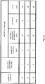
- FIG.5 shows an example of a table showing correspondence of a plurality of numbers of clusters and frequency assignment units corresponding to each number of clusters.
- the upper limit value of the number of clusters is 4.
- the number of clusters of 1 is excluded because the number indicates contiguous frequency transmission.
- the number of bits of frequency assignment information i.e. the number of bits forming a frequency assigning bit sequence
- the upper limit value of the number of clusters is set based on the relationship between the number of clusters and system throughput performance.
- FIG.6 shows the relationship between the maximum number of clusters that can be transmitted by a terminal apparatus and the average sector throughput (see Non-Patent Literature 3).
- FIG.6 shows that system throughput performance does not deteriorate even when the number of clusters is limited to around 3 to 4. This is because the probability that the number of clusters of a terminal becomes 4 or greater is low. As described above, because the influence on system throughput performance is small, it is possible to set the upper limit value to the number of clusters.
- a frequency assignment unit corresponding to each number of clusters is determined as described below.
- a reference number of clusters which constitutes a standard, is determined.
- the number of clusters that is most frequently used is selected, for example.
- the number of signaling bits that is required to report frequency resource assignment information is set as the reference number of bits.
- the frequency assignment unit having the closest number of signaling bits to the reference number of bits is selected, the number of signaling bits being required to report frequency resource assignment information using that number of clusters.
- a frequency assignment unit of 4 having the closest number of signaling bits to the reference number of bits 18 is selected when the number of clusters is 3
- a frequency assignment unit of 5 is selected when the number of clusters is 4.
- terminal apparatus 200 can reduce the number of blind decoding processing for detecting a signaling format.
- scheduling section 113 assigns a frequency resource to a terminal to which frequency is assigned, based on the set frequency assignment unit, and frequency assigning parameter setting section 112 adjusts a frequency assignment unit to set to scheduling section 113 based on the number of clusters to be applied to the terminal to which frequency is assigned.
- the number of bits forming a frequency assigning bit sequence is constant regardless of the number of clusters.
- encoding section 114 makes the total number of bits constant regardless of the number of clusters by adding padding bits (for example, a bit value of 0) before encoding a frequency assigning bit sequence.
- the numbers of signaling bits required for reporting frequency assignment information are not equal.
- encoding section 114 adds a padding bit to make the numbers of signaling bits equal, it is possible to share a signaling format, making it possible to reduce the number of blind decoding processing for detecting a signaling format at a side receiving scheduling information.
- Embodiment 2 where, as a parameter to determine a frequency assignment unit, a "system bandwidth" is adopted in addition to the number of clusters.
- FIG.9 is a block diagram showing a configuration of base station apparatus 300 according to Embodiment 2 of the present invention.
- base station apparatus 300 is provided with frequency assigning parameter setting section 301.
- Frequency assigning parameter setting section 301 maintains information about the relationship between the number of clusters and the frequency assignment unit that are applied to a terminal to which frequency is assigned, per system bandwidth.
- Frequency assigning parameter setting section 301 has, for example, a second table showing correspondence shown in FIG.10 in addition to the first table showing correspondence shown in FIG.5 .
- the system bandwidths to be used for the first table showing correspondence and the second table showing correspondence are different.
- the term "system bandwidth" refers to a bandwidth of the whole band that base station apparatus 300 can receive, that is, a bandwidth of the whole band that can be assigned to terminals in the cell covered by base station apparatus 300.
- frequency assigning parameter setting section 301 sets a frequency assignment unit according to the number of clusters indicated by the information about the number of clusters to be input, to scheduling section 113.
- Frequency assigning parameter setting section 301 uses the first table showing correspondence shown in FIG.5 when the system bandwidth is 100 [RB], and uses the second table showing correspondence shown in FIG.10 when the system bandwidth is 200 [RB]. That is, frequency assigning parameter setting section 301 switches tables showing correspondence to be used depending on the system bandwidth.
- usage rate per number of clusters of a terminal apparatus in the system changes. For example, because the amount of frequency resource that can be used by one terminal apparatus changes as the system bandwidth is broadened, it is necessary to assign larger number of clusters to a terminal apparatus to improve throughput performance.
- frequency assigning parameter setting section 301 switches tables showing correspondence to be used depending on the system bandwidth, so that it is possible to use the optimal table showing correspondence according to the system bandwidth.
- FIG.11 is a block diagram showing a configuration of terminal apparatus 400 according to Embodiment 2 of the present invention.
- terminal apparatus 400 is provided with frequency assigning parameter setting section 401.
- Frequency assigning parameter setting section 401 extracts information about the number of clusters and information about a system bandwidth that are contained in the control data received from decoding section 203. Further, frequency assigning parameter setting section 401 maintains a table showing correspondence that is similar to the table maintained in frequency assigning parameter setting section 301 of base station apparatus 300. Then, frequency assigning parameter setting section 401 outputs a frequency assignment unit corresponding to the system bandwidth indicated by the extracted information about a system bandwidth and the number of clusters indicated by the information about the number of clusters, to scheduling information setting section 205.
- frequency assigning parameter setting section 301 adjusts the frequency assignment unit to be set based on the bandwidth of the system band in addition to the number of clusters.
- Embodiment 3 where, when the number of bits forming a frequency assigning bit sequence varies depending on the number of clusters, offset information for fine-tuning the frequency assignment position is added, without padding "0" bits.
- FIG.12 is a block diagram showing a configuration of base station apparatus 500 according to Embodiment 3 of the present invention.
- base station apparatus 500 is provided with frequency assigning parameter setting section 501 and scheduling section 502.
- Frequency assigning parameter setting section 501 determines whether or not to shift the frequency resource assigned in scheduling section 502, in a direction of frequency, based on the channel estimation value received from channel estimation section 107.
- the standard for deciding whether or not to perform shifting is based on the channel quality in the RB to be assigned. For example, the RB to be assigned having a higher average SINR is selected by calculating average SINRs in the RBs to be assigned for the cases where shifting is performed and not performed.
- Scheduling section 502 forms a frequency assigning bit sequence as scheduling section 113 does. Further, scheduling section 502 adds offset information to a frequency assigning bit sequence according to the result of determination in frequency assigning parameter setting section 501. For example, as shown in FIG.13 , the bit value of 0 is set as offset information when determination not to perform shifting is made, while the bit value of 1 is set as offset information when shifting is performed. An example of a table showing correspondence in this case is shown in FIG.14 .
- frequency assigning parameter setting section 501 determines whether or not to shift the frequency resource assigned in scheduling section 502, in a direction of frequency, based on the channel estimation value, and scheduling section 502 adds offset information to a frequency assigning bit sequence corresponding to the result of determination in frequency assigning parameter setting section 501.
- Each function block employed in the description of each of the aforementioned embodiments may typically be implemented as an LSI constituted by an integrated circuit. These may be individual chips or partially or totally contained on a single chip. "LSI” is adopted here but this may also be referred to as “IC,” “system LSI,” “super LSI,” or “ultra LSI” depending on differing extents of integration.
- circuit integration is not limited to LSI's, and implementation using dedicated circuitry or general purpose processors is also possible.
- LSI manufacture utilization of a programmable FPGA (Field Programmable Gate Array) or a reconfigurable processor where connections and settings of circuit cells within an LSI can be reconfigured is also possible.
- FPGA Field Programmable Gate Array
- a scheduling apparatus and a scheduling method according to the present invention is useful for maintaining system throughput performance and reducing the amount of signaling for frequency resource assignment information.
Landscapes
- Engineering & Computer Science (AREA)
- Signal Processing (AREA)
- Computer Networks & Wireless Communication (AREA)
- Quality & Reliability (AREA)
- Mobile Radio Communication Systems (AREA)
Claims (8)
- Planungseinrichtung (300), umfassend:eine Frequenzzuteilungsfestsetzungseinheit (301), die konfiguriert ist, gemäß einer Systembandbreite und einer Clusterzahl eine Ressourcenblockgruppengröße festzulegen, die an eine Endvorrichtung (400) zugewiesen wird;wobei die Ressourcenblockgruppengröße eine Anzahl zusammenhängender Ressourcenblöcke ist, die in einer zugehörigen Ressourcenblockgruppe enthalten sind, und wobei jedes der Cluster gemäß der festgelegten Ressourcenblockgruppengröße einen oder mehrere Ressourcenblockgruppen umfasst; undwobei die Planungsvorrichtung (300) ferner umfasst:einen Planer (300), welcher konfiguriert ist, basierend auf der Ressourcenblockgruppengröße einer Endvorrichtung (400) eine Frequenzressource zuzuweisen, die durch die Frequenzzuteilungsfestsetzungseinheit (301) festgelegt wird,dadurch gekennzeichnet, dassein Wert, welcher als Ressourcenblockgruppengröße festgelegt wird, von der Systembandbreite und der Clusterzahl abhängt; undwobei jedes Cluster, welches der Endvorrichtung (400) zugewiesen ist, getrennt von einem anderen Cluster ist, welches im Frequenzbereich auch der Endvorrichtung (400) zugewiesen ist.
- Planungseinrichtung (300) gemäß Anspruch 1, ferner eine Meldeeinheit umfassend, welche konfiguriert ist, die Systembandbreite basierend auf der festgelegten Ressourcenblockgröße in eine Vielzahl von Ressourcenblocks zu unterteilen, und die ferner konfiguriert ist, der Endvorrichtung (400) eine Frequenzzuweisungsbitsequenz zu melden, die einem Anordnungsmuster von Ressourcenblockgruppen entspricht, die der Endvorrichtung zugewiesen sind und von Ressourcenblockgruppen, die der Endvorrichtung nicht zugewiesen sind, entspricht.
- Planungseinrichtung (300) nach Anspruch 2, wobei eine Anzahl von Bits, die die Frequenzzuweisungsbitsequenz bilden, unabhängig von der Clusterzahl konstant ist.
- Planungseinrichtung (300) gemäß Anspruch 2, ferner eine Kanalschätzeinheit (107) enthaltend, die konfiguriert ist, basierend auf einem Referenzsignal, welches von der Endvorrichtung (400) übertragen wird, einen Kanalschätzwert zu berechnen, wobei:die Frequenzzuweisungsfestsetzungseinheit (501) ferner konfiguriert ist, zu bestimmen, ob die Frequenzressource, die durch den Planer (502) zugewiesen wird, basierend auf dem Kanalschätzwert zu einem höheren Frequenzbereich verschoben wird; undder Planer (502) ferner konfiguriert ist, Offset-Information entsprechend einem Ergebnis der Bestimmung der Frequenzzuweisungsfestsetzungseinheit (501) an der Frequenzzuweisungsbitsequenz hinzuzufügen.
- Ein Planungsverfahren, welches den Schritt umfasst,
Festlegen einer Ressourcenblockgruppengröße, die einer Endvorrichtung zuzuweisen ist, über eine frequenzzuweisungsfestlegende Einheit gemäß einer Systembandbreite und einer Anzahl von Clustern,
wobei die Ressourcenblockgruppengröße eine Anzahl zusammenhängender Ressourcenblöcke ist, die in einer entsprechenden Ressourcenblockgruppe enthalten ist, und wobei jedes der Cluster gemäß der festgelegten Ressourcenblockgruppengröße eine oder mehrere Ressourcenblockgruppen enthält; und
wobei das Verfahren ferner den Schritt umfasst:Zuweisen einer Frequenzressource an die Endvorrichtung, welche durch die Frequenzzuweisungsfestsetzungseinheit festgelegt wird;Zuweisen einer Frequenzressource an die Endvorrichtung, welche durch die frequenzzuweisungsfestlegende Einheit festgelegt wird, über einen Planer basierend auf der Ressourcenblockgröße,dadurch gekennzeichnet,dass ein Wert, welcher durch die Ressourcenblockgruppengröße festgelegt ist, von der Systembandbreite und der Clusterzahl abhängt; undwobei jedes Cluster, welches der Endvorrichtung (400) zugewiesen ist, im Frequenzbereich getrennt von einem anderen Cluster ist, welches auch der Endvorrichtung (400) zugewiesen ist. - Verfahren gemäß Anspruch 5, ferner folgende Schritte umfassend:Aufteilen der Systembandbreite basierend auf der festgelegten Ressourcenblockgruppengröße in eine Vielzahl von Ressourcenblockgruppen durch eine Meldeeinheit; undMelden einer Frequenzzuweisungsbitsequenz an die Endvorrichtung entsprechend der Anordnung der Ressourcenblockgruppen, welche der Endvorrichtung zugeordnet sind und der Ressourcenblockgruppen, welche der Endvorrichtung nicht zugeordnet sind.
- Verfahren gemäß Anspruch 6, wobei die Anzahl von Bits, welche die Frequenzzuweisungsbitsequenz bilden, unabhängig von der Anzahl von Clustern konstant ist.
- Verfahren gemäß Anspruch 6, welches ferner folgende Schritte umfasst:Berechnen eines Kanalschätzwerts über eine Kanalschätzeinheit basierend auf einem Referenzsignal, welches von dem Endgerät übertragen wird,Ermitteln über die Frequenzzuweisungsfestsetzungseinheit, ob die Frequenzressource, die durch den Planer zugewiesen ist, basierend auf dem Kanalschätzwert in einen höheren Frequenzbereich verschoben wird; undHinzufügen einer Offset-Information zu der Frequenzzuweisungsbitsequenz, entsprechend dem Ergebnis der Bestimmung der Frequenzzuweisungsfestsetzungseinheit, über den Planer.
Priority Applications (6)
| Application Number | Priority Date | Filing Date | Title |
|---|---|---|---|
| EP21195194.2A EP3962210B1 (de) | 2009-02-18 | 2010-02-17 | Integrierte schaltung für kommunikation |
| EP18172702.5A EP3379880B1 (de) | 2009-02-18 | 2010-02-17 | Kommunikationsvorrichtung und verfahren |
| EP23162418.0A EP4221404A1 (de) | 2009-02-18 | 2010-02-17 | Planungsvorrichtung und planungsverfahren |
| SI201031757T SI2400807T1 (sl) | 2009-02-18 | 2010-02-17 | Naprava za razporejanje in postopek razporejanja |
| PL10743560T PL2400807T3 (pl) | 2009-02-18 | 2010-02-17 | Urządzenie planujące i sposób planowania |
| HRP20181636TT HRP20181636T1 (hr) | 2009-02-18 | 2018-10-11 | Uređaj za planiranje i metoda planiranja |
Applications Claiming Priority (2)
| Application Number | Priority Date | Filing Date | Title |
|---|---|---|---|
| JP2009035617 | 2009-02-18 | ||
| PCT/JP2010/001008 WO2010095430A1 (ja) | 2009-02-18 | 2010-02-17 | スケジューリング装置及びスケジューリング方法 |
Related Child Applications (4)
| Application Number | Title | Priority Date | Filing Date |
|---|---|---|---|
| EP23162418.0A Division EP4221404A1 (de) | 2009-02-18 | 2010-02-17 | Planungsvorrichtung und planungsverfahren |
| EP21195194.2A Division EP3962210B1 (de) | 2009-02-18 | 2010-02-17 | Integrierte schaltung für kommunikation |
| EP18172702.5A Division-Into EP3379880B1 (de) | 2009-02-18 | 2010-02-17 | Kommunikationsvorrichtung und verfahren |
| EP18172702.5A Division EP3379880B1 (de) | 2009-02-18 | 2010-02-17 | Kommunikationsvorrichtung und verfahren |
Publications (3)
| Publication Number | Publication Date |
|---|---|
| EP2400807A1 EP2400807A1 (de) | 2011-12-28 |
| EP2400807A4 EP2400807A4 (de) | 2015-11-04 |
| EP2400807B1 true EP2400807B1 (de) | 2018-07-11 |
Family
ID=42633718
Family Applications (4)
| Application Number | Title | Priority Date | Filing Date |
|---|---|---|---|
| EP23162418.0A Pending EP4221404A1 (de) | 2009-02-18 | 2010-02-17 | Planungsvorrichtung und planungsverfahren |
| EP21195194.2A Active EP3962210B1 (de) | 2009-02-18 | 2010-02-17 | Integrierte schaltung für kommunikation |
| EP10743560.4A Active EP2400807B1 (de) | 2009-02-18 | 2010-02-17 | Terminplanungsvorrichtung und terminplanungsverfahren |
| EP18172702.5A Active EP3379880B1 (de) | 2009-02-18 | 2010-02-17 | Kommunikationsvorrichtung und verfahren |
Family Applications Before (2)
| Application Number | Title | Priority Date | Filing Date |
|---|---|---|---|
| EP23162418.0A Pending EP4221404A1 (de) | 2009-02-18 | 2010-02-17 | Planungsvorrichtung und planungsverfahren |
| EP21195194.2A Active EP3962210B1 (de) | 2009-02-18 | 2010-02-17 | Integrierte schaltung für kommunikation |
Family Applications After (1)
| Application Number | Title | Priority Date | Filing Date |
|---|---|---|---|
| EP18172702.5A Active EP3379880B1 (de) | 2009-02-18 | 2010-02-17 | Kommunikationsvorrichtung und verfahren |
Country Status (20)
| Country | Link |
|---|---|
| US (8) | US9112651B2 (de) |
| EP (4) | EP4221404A1 (de) |
| JP (10) | JP5389151B2 (de) |
| KR (2) | KR101567130B1 (de) |
| CN (2) | CN102318424B (de) |
| BR (1) | BRPI1008459B8 (de) |
| CA (1) | CA2752564C (de) |
| CY (1) | CY1120760T1 (de) |
| DK (1) | DK2400807T3 (de) |
| ES (1) | ES2689969T3 (de) |
| HR (1) | HRP20181636T1 (de) |
| HU (1) | HUE040607T2 (de) |
| LT (1) | LT2400807T (de) |
| MY (2) | MY166138A (de) |
| PL (1) | PL2400807T3 (de) |
| PT (1) | PT2400807T (de) |
| RU (1) | RU2510804C2 (de) |
| SI (1) | SI2400807T1 (de) |
| WO (1) | WO2010095430A1 (de) |
| ZA (1) | ZA201105982B (de) |
Families Citing this family (11)
| Publication number | Priority date | Publication date | Assignee | Title |
|---|---|---|---|---|
| KR101567130B1 (ko) | 2009-02-18 | 2015-11-09 | 파나소닉 인텔렉츄얼 프로퍼티 코포레이션 오브 아메리카 | 단말 장치 및 매핑 방법 |
| US9686062B2 (en) * | 2011-03-04 | 2017-06-20 | Alcatel Lucent | Virtual aggregation of fragmented wireless spectrum |
| WO2012173385A2 (ko) * | 2011-06-13 | 2012-12-20 | 엘지전자 주식회사 | 무선통신 시스템에서 자원 할당 방법 및 장치 |
| JP6168310B2 (ja) * | 2011-11-25 | 2017-07-26 | 日本電気株式会社 | マシンタイプ通信を提供する装置及び方法 |
| CN103139924B (zh) * | 2011-12-05 | 2016-08-31 | 华为技术有限公司 | 一种调度资源的方法及装置 |
| US20160135056A1 (en) * | 2014-11-06 | 2016-05-12 | Htc Corporation | Device of Handling Measurement Signal on Unlicensed Carrier |
| CN106162906B (zh) * | 2015-03-31 | 2019-01-15 | 中兴通讯股份有限公司 | 调度信息发送、接收方法及装置 |
| WO2016201739A1 (zh) * | 2015-06-16 | 2016-12-22 | 华为技术有限公司 | 资源调度的方法、装置和设备 |
| WO2018030418A1 (ja) * | 2016-08-10 | 2018-02-15 | 株式会社Nttドコモ | ユーザ端末及び無線通信方法 |
| WO2019095232A1 (zh) * | 2017-11-16 | 2019-05-23 | 富士通株式会社 | 资源指示方法、装置及通信系统 |
| SG11202011477QA (en) * | 2018-06-29 | 2021-01-28 | Guangdong Oppo Mobile Telecommunications Corp Ltd | Method for determining sidelink category, terminal device, and network device |
Citations (1)
| Publication number | Priority date | Publication date | Assignee | Title |
|---|---|---|---|---|
| EP3131358A1 (de) * | 2009-01-30 | 2017-02-15 | Samsung Electronics Co., Ltd. | Steuersignalisierung für übertragungen über benachbarte und nicht benachbarte frequenzbänder |
Family Cites Families (18)
| Publication number | Priority date | Publication date | Assignee | Title |
|---|---|---|---|---|
| US7068683B1 (en) * | 2000-10-25 | 2006-06-27 | Qualcomm, Incorporated | Method and apparatus for high rate packet data and low delay data transmissions |
| GB2370452B (en) | 2000-12-19 | 2004-10-20 | Inmarsat Ltd | Communication method and apparatus |
| JP4527067B2 (ja) * | 2005-03-31 | 2010-08-18 | 株式会社エヌ・ティ・ティ・ドコモ | 移動局、送信方法及び移動通信システム |
| WO2007029965A1 (en) * | 2005-09-06 | 2007-03-15 | Electronics And Telecommunications Research Institute | Method for resource partition, assignment, transmission and reception for inter-cell interference migration in downlink of ofdm cellular systems |
| GB2436416A (en) * | 2006-03-20 | 2007-09-26 | Nec Corp | Signal resource allocation in a communication system using a plurality of subcarriers |
| JP4295300B2 (ja) * | 2006-08-22 | 2009-07-15 | 株式会社エヌ・ティ・ティ・ドコモ | 送信装置及び送信方法 |
| KR101319877B1 (ko) * | 2006-11-01 | 2013-10-18 | 엘지전자 주식회사 | 자원 할당 방법 및 자원 할당 정보 전송 방법 |
| US9137821B2 (en) * | 2007-05-02 | 2015-09-15 | Qualcomm Incorporated | Flexible signaling of resources on a control channel |
| US8179775B2 (en) * | 2007-08-14 | 2012-05-15 | Texas Instruments Incorporated | Precoding matrix feedback processes, circuits and systems |
| JP5505921B2 (ja) | 2007-08-01 | 2014-05-28 | 株式会社イノアックコーポレーション | 軟質ポリウレタン発泡体 |
| CN101127719B (zh) | 2007-09-27 | 2013-03-20 | 中兴通讯股份有限公司 | 用于lte系统的无线资源分配的指示方法 |
| GB2457242A (en) * | 2008-02-05 | 2009-08-12 | Nec Corp | Resource allocation in a communication system |
| JP5440802B2 (ja) | 2008-06-20 | 2014-03-12 | 日本電気株式会社 | リソース割当方法、特定方法、無線通信システム、基地局、移動局、及びプログラム |
| US8379581B2 (en) * | 2008-12-08 | 2013-02-19 | Sharp Kabushiki Kaisha | Systems and methods for uplink power control |
| KR101567130B1 (ko) * | 2009-02-18 | 2015-11-09 | 파나소닉 인텔렉츄얼 프로퍼티 코포레이션 오브 아메리카 | 단말 장치 및 매핑 방법 |
| CN101657018B (zh) * | 2009-08-18 | 2015-01-28 | 中兴通讯股份有限公司 | 无线信道资源分配的指示方法及基站、解码方法及终端 |
| US9949261B2 (en) * | 2009-10-15 | 2018-04-17 | Qualcomm Incorporated | Method and apparatus for conveying resource assignment for multiple system bandwidths |
| JP5778933B2 (ja) * | 2011-01-28 | 2015-09-16 | キヤノン株式会社 | 印刷装置、印刷装置の制御方法、及びプログラム |
-
2010
- 2010-02-17 KR KR1020127022166A patent/KR101567130B1/ko active IP Right Grant
- 2010-02-17 CN CN201080008096.6A patent/CN102318424B/zh active Active
- 2010-02-17 RU RU2011134498/07A patent/RU2510804C2/ru active
- 2010-02-17 BR BRPI1008459A patent/BRPI1008459B8/pt active IP Right Grant
- 2010-02-17 EP EP23162418.0A patent/EP4221404A1/de active Pending
- 2010-02-17 CA CA2752564A patent/CA2752564C/en active Active
- 2010-02-17 PL PL10743560T patent/PL2400807T3/pl unknown
- 2010-02-17 JP JP2011500513A patent/JP5389151B2/ja active Active
- 2010-02-17 WO PCT/JP2010/001008 patent/WO2010095430A1/ja active Application Filing
- 2010-02-17 PT PT10743560T patent/PT2400807T/pt unknown
- 2010-02-17 HU HUE10743560A patent/HUE040607T2/hu unknown
- 2010-02-17 MY MYPI2011003834A patent/MY166138A/en unknown
- 2010-02-17 KR KR1020117019105A patent/KR101567124B1/ko active IP Right Grant
- 2010-02-17 ES ES10743560.4T patent/ES2689969T3/es active Active
- 2010-02-17 MY MYPI2017001042A patent/MY184502A/en unknown
- 2010-02-17 US US13/201,767 patent/US9112651B2/en active Active
- 2010-02-17 EP EP21195194.2A patent/EP3962210B1/de active Active
- 2010-02-17 EP EP10743560.4A patent/EP2400807B1/de active Active
- 2010-02-17 SI SI201031757T patent/SI2400807T1/sl unknown
- 2010-02-17 CN CN201310704034.4A patent/CN103701578B/zh active Active
- 2010-02-17 EP EP18172702.5A patent/EP3379880B1/de active Active
- 2010-02-17 LT LTEP10743560.4T patent/LT2400807T/lt unknown
- 2010-02-17 DK DK10743560.4T patent/DK2400807T3/en active
-
2011
- 2011-08-16 ZA ZA2011/05982A patent/ZA201105982B/en unknown
-
2013
- 2013-10-02 JP JP2013207260A patent/JP5698816B2/ja active Active
-
2015
- 2015-02-12 JP JP2015025533A patent/JP6132167B2/ja active Active
- 2015-07-14 US US14/799,316 patent/US9397803B2/en active Active
-
2016
- 2016-07-19 US US15/214,134 patent/US9667393B2/en active Active
-
2017
- 2017-04-04 JP JP2017074629A patent/JP6323737B2/ja active Active
- 2017-04-26 US US15/498,036 patent/US9888477B2/en active Active
- 2017-12-28 US US15/857,465 patent/US10568099B2/en active Active
-
2018
- 2018-03-27 JP JP2018060278A patent/JP6474013B2/ja active Active
- 2018-10-03 CY CY181101019T patent/CY1120760T1/el unknown
- 2018-10-11 HR HRP20181636TT patent/HRP20181636T1/hr unknown
-
2019
- 2019-01-17 JP JP2019006125A patent/JP6635422B2/ja active Active
- 2019-12-06 JP JP2019221480A patent/JP6796811B2/ja active Active
- 2019-12-17 US US16/717,344 patent/US11240806B2/en active Active
-
2020
- 2020-10-29 JP JP2020181290A patent/JP6982813B2/ja active Active
-
2021
- 2021-11-02 JP JP2021179402A patent/JP7345098B2/ja active Active
- 2021-12-16 US US17/553,497 patent/US11751181B2/en active Active
-
2023
- 2023-07-18 US US18/354,438 patent/US20230362909A1/en active Pending
- 2023-08-21 JP JP2023134014A patent/JP2023164853A/ja active Pending
Patent Citations (1)
| Publication number | Priority date | Publication date | Assignee | Title |
|---|---|---|---|---|
| EP3131358A1 (de) * | 2009-01-30 | 2017-02-15 | Samsung Electronics Co., Ltd. | Steuersignalisierung für übertragungen über benachbarte und nicht benachbarte frequenzbänder |
Also Published As
Similar Documents
| Publication | Publication Date | Title |
|---|---|---|
| US11751181B2 (en) | Integrated circuit, apparatus and method for communication using resource block groups | |
| US10771217B2 (en) | Wireless base station apparatus, wireless terminal apparatus, frequency resource allocation method, and method of forming transmission signal |
Legal Events
| Date | Code | Title | Description |
|---|---|---|---|
| PUAI | Public reference made under article 153(3) epc to a published international application that has entered the european phase |
Free format text: ORIGINAL CODE: 0009012 |
|
| 17P | Request for examination filed |
Effective date: 20110817 |
|
| AK | Designated contracting states |
Kind code of ref document: A1 Designated state(s): AT BE BG CH CY CZ DE DK EE ES FI FR GB GR HR HU IE IS IT LI LT LU LV MC MK MT NL NO PL PT RO SE SI SK SM TR |
|
| DAX | Request for extension of the european patent (deleted) | ||
| RAP1 | Party data changed (applicant data changed or rights of an application transferred) |
Owner name: PANASONIC INTELLECTUAL PROPERTY CORPORATION OF AME |
|
| RA4 | Supplementary search report drawn up and despatched (corrected) |
Effective date: 20151006 |
|
| RIC1 | Information provided on ipc code assigned before grant |
Ipc: H04W 72/04 20090101AFI20150930BHEP Ipc: H04J 1/00 20060101ALI20150930BHEP Ipc: H04J 11/00 20060101ALI20150930BHEP |
|
| RAP1 | Party data changed (applicant data changed or rights of an application transferred) |
Owner name: SUN PATENT TRUST |
|
| STAA | Information on the status of an ep patent application or granted ep patent |
Free format text: STATUS: EXAMINATION IS IN PROGRESS |
|
| 17Q | First examination report despatched |
Effective date: 20170724 |
|
| REG | Reference to a national code |
Ref country code: DE Ref legal event code: R079 Ref document number: 602010051835 Country of ref document: DE Free format text: PREVIOUS MAIN CLASS: H04W0072040000 Ipc: H04L0005000000 |
|
| GRAP | Despatch of communication of intention to grant a patent |
Free format text: ORIGINAL CODE: EPIDOSNIGR1 |
|
| STAA | Information on the status of an ep patent application or granted ep patent |
Free format text: STATUS: GRANT OF PATENT IS INTENDED |
|
| RIC1 | Information provided on ipc code assigned before grant |
Ipc: H04L 5/00 20060101AFI20180119BHEP Ipc: H04W 72/04 20090101ALI20180119BHEP Ipc: H04W 72/08 20090101ALI20180119BHEP |
|
| INTG | Intention to grant announced |
Effective date: 20180209 |
|
| GRAS | Grant fee paid |
Free format text: ORIGINAL CODE: EPIDOSNIGR3 |
|
| GRAA | (expected) grant |
Free format text: ORIGINAL CODE: 0009210 |
|
| STAA | Information on the status of an ep patent application or granted ep patent |
Free format text: STATUS: THE PATENT HAS BEEN GRANTED |
|
| AK | Designated contracting states |
Kind code of ref document: B1 Designated state(s): AT BE BG CH CY CZ DE DK EE ES FI FR GB GR HR HU IE IS IT LI LT LU LV MC MK MT NL NO PL PT RO SE SI SK SM TR |
|
| REG | Reference to a national code |
Ref country code: GB Ref legal event code: FG4D |
|
| REG | Reference to a national code |
Ref country code: CH Ref legal event code: EP |
|
| REG | Reference to a national code |
Ref country code: AT Ref legal event code: REF Ref document number: 1018021 Country of ref document: AT Kind code of ref document: T Effective date: 20180715 |
|
| REG | Reference to a national code |
Ref country code: DE Ref legal event code: R096 Ref document number: 602010051835 Country of ref document: DE |
|
| REG | Reference to a national code |
Ref country code: IE Ref legal event code: FG4D |
|
| REG | Reference to a national code |
Ref country code: HR Ref legal event code: TUEP Ref document number: P20181636 Country of ref document: HR Ref country code: RO Ref legal event code: EPE |
|
| REG | Reference to a national code |
Ref country code: NL Ref legal event code: FP |
|
| REG | Reference to a national code |
Ref country code: DK Ref legal event code: T3 Effective date: 20181016 |
|
| REG | Reference to a national code |
Ref country code: SE Ref legal event code: TRGR |
|
| REG | Reference to a national code |
Ref country code: PT Ref legal event code: SC4A Ref document number: 2400807 Country of ref document: PT Date of ref document: 20181105 Kind code of ref document: T Free format text: AVAILABILITY OF NATIONAL TRANSLATION Effective date: 20181008 |
|
| REG | Reference to a national code |
Ref country code: EE Ref legal event code: FG4A Ref document number: E016125 Country of ref document: EE Effective date: 20180926 |
|
| REG | Reference to a national code |
Ref country code: ES Ref legal event code: FG2A Ref document number: 2689969 Country of ref document: ES Kind code of ref document: T3 Effective date: 20181116 |
|
| REG | Reference to a national code |
Ref country code: NO Ref legal event code: T2 Effective date: 20180711 |
|
| REG | Reference to a national code |
Ref country code: HR Ref legal event code: T1PR Ref document number: P20181636 Country of ref document: HR |
|
| REG | Reference to a national code |
Ref country code: SK Ref legal event code: T3 Ref document number: E 28714 Country of ref document: SK |
|
| REG | Reference to a national code |
Ref country code: HR Ref legal event code: ODRP Ref document number: P20181636 Country of ref document: HR Payment date: 20190131 Year of fee payment: 10 |
|
| REG | Reference to a national code |
Ref country code: GR Ref legal event code: EP Ref document number: 20180402762 Country of ref document: GR Effective date: 20190225 |
|
| REG | Reference to a national code |
Ref country code: HU Ref legal event code: AG4A Ref document number: E040607 Country of ref document: HU |
|
| REG | Reference to a national code |
Ref country code: DE Ref legal event code: R097 Ref document number: 602010051835 Country of ref document: DE |
|
| PLBE | No opposition filed within time limit |
Free format text: ORIGINAL CODE: 0009261 |
|
| STAA | Information on the status of an ep patent application or granted ep patent |
Free format text: STATUS: NO OPPOSITION FILED WITHIN TIME LIMIT |
|
| 26N | No opposition filed |
Effective date: 20190412 |
|
| REG | Reference to a national code |
Ref country code: HR Ref legal event code: ODRP Ref document number: P20181636 Country of ref document: HR Payment date: 20200131 Year of fee payment: 11 |
|
| REG | Reference to a national code |
Ref country code: HR Ref legal event code: ODRP Ref document number: P20181636 Country of ref document: HR Payment date: 20210205 Year of fee payment: 12 |
|
| REG | Reference to a national code |
Ref country code: AT Ref legal event code: UEP Ref document number: 1018021 Country of ref document: AT Kind code of ref document: T Effective date: 20180711 |
|
| REG | Reference to a national code |
Ref country code: HR Ref legal event code: ODRP Ref document number: P20181636 Country of ref document: HR Payment date: 20220214 Year of fee payment: 13 |
|
| REG | Reference to a national code |
Ref country code: HR Ref legal event code: ODRP Ref document number: P20181636 Country of ref document: HR Payment date: 20230214 Year of fee payment: 14 |
|
| PGFP | Annual fee paid to national office [announced via postgrant information from national office to epo] |
Ref country code: NO Payment date: 20230220 Year of fee payment: 14 Ref country code: FR Payment date: 20230221 Year of fee payment: 14 Ref country code: DK Payment date: 20230220 Year of fee payment: 14 |
|
| PGFP | Annual fee paid to national office [announced via postgrant information from national office to epo] |
Ref country code: TR Payment date: 20230216 Year of fee payment: 14 Ref country code: SE Payment date: 20230216 Year of fee payment: 14 Ref country code: PL Payment date: 20230213 Year of fee payment: 14 Ref country code: LV Payment date: 20230215 Year of fee payment: 14 Ref country code: IT Payment date: 20230223 Year of fee payment: 14 Ref country code: HR Payment date: 20230214 Year of fee payment: 14 Ref country code: CY Payment date: 20230213 Year of fee payment: 14 Ref country code: BE Payment date: 20230216 Year of fee payment: 14 |
|
| P01 | Opt-out of the competence of the unified patent court (upc) registered |
Effective date: 20230517 |
|
| PGFP | Annual fee paid to national office [announced via postgrant information from national office to epo] |
Ref country code: MT Payment date: 20230206 Year of fee payment: 14 |
|
| PGFP | Annual fee paid to national office [announced via postgrant information from national office to epo] |
Ref country code: PT Payment date: 20231221 Year of fee payment: 15 |
|
| PGFP | Annual fee paid to national office [announced via postgrant information from national office to epo] |
Ref country code: MK Payment date: 20230123 Year of fee payment: 14 |
|
| REG | Reference to a national code |
Ref country code: HR Ref legal event code: ODRP Ref document number: P20181636 Country of ref document: HR Payment date: 20240209 Year of fee payment: 15 |
|
| PGFP | Annual fee paid to national office [announced via postgrant information from national office to epo] |
Ref country code: LU Payment date: 20240220 Year of fee payment: 15 |
|
| PGFP | Annual fee paid to national office [announced via postgrant information from national office to epo] |
Ref country code: GR Payment date: 20240221 Year of fee payment: 15 |
|
| PGFP | Annual fee paid to national office [announced via postgrant information from national office to epo] |
Ref country code: IS Payment date: 20240212 Year of fee payment: 15 |
|
| PGFP | Annual fee paid to national office [announced via postgrant information from national office to epo] |
Ref country code: LT Payment date: 20240123 Year of fee payment: 15 |
|
| PGFP | Annual fee paid to national office [announced via postgrant information from national office to epo] |
Ref country code: ES Payment date: 20240325 Year of fee payment: 15 Ref country code: NL Payment date: 20240219 Year of fee payment: 15 Ref country code: IE Payment date: 20240219 Year of fee payment: 15 |
|
| PGFP | Annual fee paid to national office [announced via postgrant information from national office to epo] |
Ref country code: AT Payment date: 20240220 Year of fee payment: 15 |
|
| PGFP | Annual fee paid to national office [announced via postgrant information from national office to epo] |
Ref country code: MC Payment date: 20240226 Year of fee payment: 15 |
|
| PGFP | Annual fee paid to national office [announced via postgrant information from national office to epo] |
Ref country code: SM Payment date: 20240129 Year of fee payment: 15 Ref country code: RO Payment date: 20240208 Year of fee payment: 15 Ref country code: HU Payment date: 20240222 Year of fee payment: 15 Ref country code: FI Payment date: 20240219 Year of fee payment: 15 Ref country code: EE Payment date: 20240215 Year of fee payment: 15 Ref country code: DE Payment date: 20240219 Year of fee payment: 15 Ref country code: CZ Payment date: 20240208 Year of fee payment: 15 Ref country code: BG Payment date: 20240222 Year of fee payment: 15 Ref country code: GB Payment date: 20240219 Year of fee payment: 15 Ref country code: CH Payment date: 20240301 Year of fee payment: 15 Ref country code: SK Payment date: 20240212 Year of fee payment: 15 |
|
| PGFP | Annual fee paid to national office [announced via postgrant information from national office to epo] |
Ref country code: SI Payment date: 20240208 Year of fee payment: 15 |