EP3553964A1 - Signalübertragungsverfahren, netzwerkvorrichtung und endgerätevorrichtung - Google Patents
Signalübertragungsverfahren, netzwerkvorrichtung und endgerätevorrichtung Download PDFInfo
- Publication number
- EP3553964A1 EP3553964A1 EP17889615.5A EP17889615A EP3553964A1 EP 3553964 A1 EP3553964 A1 EP 3553964A1 EP 17889615 A EP17889615 A EP 17889615A EP 3553964 A1 EP3553964 A1 EP 3553964A1
- Authority
- EP
- European Patent Office
- Prior art keywords
- terminal device
- reference signals
- network device
- sending
- channel quality
- Prior art date
- Legal status (The legal status is an assumption and is not a legal conclusion. Google has not performed a legal analysis and makes no representation as to the accuracy of the status listed.)
- Granted
Links
Images


Classifications
-
- H—ELECTRICITY
- H04—ELECTRIC COMMUNICATION TECHNIQUE
- H04B—TRANSMISSION
- H04B7/00—Radio transmission systems, i.e. using radiation field
- H04B7/02—Diversity systems; Multi-antenna system, i.e. transmission or reception using multiple antennas
- H04B7/04—Diversity systems; Multi-antenna system, i.e. transmission or reception using multiple antennas using two or more spaced independent antennas
- H04B7/06—Diversity systems; Multi-antenna system, i.e. transmission or reception using multiple antennas using two or more spaced independent antennas at the transmitting station
- H04B7/0613—Diversity systems; Multi-antenna system, i.e. transmission or reception using multiple antennas using two or more spaced independent antennas at the transmitting station using simultaneous transmission
- H04B7/0615—Diversity systems; Multi-antenna system, i.e. transmission or reception using multiple antennas using two or more spaced independent antennas at the transmitting station using simultaneous transmission of weighted versions of same signal
- H04B7/0617—Diversity systems; Multi-antenna system, i.e. transmission or reception using multiple antennas using two or more spaced independent antennas at the transmitting station using simultaneous transmission of weighted versions of same signal for beam forming
-
- H—ELECTRICITY
- H04—ELECTRIC COMMUNICATION TECHNIQUE
- H04L—TRANSMISSION OF DIGITAL INFORMATION, e.g. TELEGRAPHIC COMMUNICATION
- H04L5/00—Arrangements affording multiple use of the transmission path
- H04L5/003—Arrangements for allocating sub-channels of the transmission path
- H04L5/0048—Allocation of pilot signals, i.e. of signals known to the receiver
- H04L5/0051—Allocation of pilot signals, i.e. of signals known to the receiver of dedicated pilots, i.e. pilots destined for a single user or terminal
-
- H—ELECTRICITY
- H04—ELECTRIC COMMUNICATION TECHNIQUE
- H04B—TRANSMISSION
- H04B7/00—Radio transmission systems, i.e. using radiation field
- H04B7/02—Diversity systems; Multi-antenna system, i.e. transmission or reception using multiple antennas
- H04B7/04—Diversity systems; Multi-antenna system, i.e. transmission or reception using multiple antennas using two or more spaced independent antennas
- H04B7/0413—MIMO systems
- H04B7/0417—Feedback systems
-
- H—ELECTRICITY
- H04—ELECTRIC COMMUNICATION TECHNIQUE
- H04B—TRANSMISSION
- H04B7/00—Radio transmission systems, i.e. using radiation field
- H04B7/02—Diversity systems; Multi-antenna system, i.e. transmission or reception using multiple antennas
- H04B7/04—Diversity systems; Multi-antenna system, i.e. transmission or reception using multiple antennas using two or more spaced independent antennas
- H04B7/06—Diversity systems; Multi-antenna system, i.e. transmission or reception using multiple antennas using two or more spaced independent antennas at the transmitting station
- H04B7/0613—Diversity systems; Multi-antenna system, i.e. transmission or reception using multiple antennas using two or more spaced independent antennas at the transmitting station using simultaneous transmission
- H04B7/0615—Diversity systems; Multi-antenna system, i.e. transmission or reception using multiple antennas using two or more spaced independent antennas at the transmitting station using simultaneous transmission of weighted versions of same signal
- H04B7/0619—Diversity systems; Multi-antenna system, i.e. transmission or reception using multiple antennas using two or more spaced independent antennas at the transmitting station using simultaneous transmission of weighted versions of same signal using feedback from receiving side
- H04B7/0621—Feedback content
- H04B7/0632—Channel quality parameters, e.g. channel quality indicator [CQI]
-
- H—ELECTRICITY
- H04—ELECTRIC COMMUNICATION TECHNIQUE
- H04B—TRANSMISSION
- H04B7/00—Radio transmission systems, i.e. using radiation field
- H04B7/02—Diversity systems; Multi-antenna system, i.e. transmission or reception using multiple antennas
- H04B7/04—Diversity systems; Multi-antenna system, i.e. transmission or reception using multiple antennas using two or more spaced independent antennas
- H04B7/06—Diversity systems; Multi-antenna system, i.e. transmission or reception using multiple antennas using two or more spaced independent antennas at the transmitting station
- H04B7/0686—Hybrid systems, i.e. switching and simultaneous transmission
- H04B7/0695—Hybrid systems, i.e. switching and simultaneous transmission using beam selection
- H04B7/06952—Selecting one or more beams from a plurality of beams, e.g. beam training, management or sweeping
- H04B7/06966—Selecting one or more beams from a plurality of beams, e.g. beam training, management or sweeping using beam correspondence; using channel reciprocity, e.g. downlink beam training based on uplink sounding reference signal [SRS]
-
- H—ELECTRICITY
- H04—ELECTRIC COMMUNICATION TECHNIQUE
- H04B—TRANSMISSION
- H04B7/00—Radio transmission systems, i.e. using radiation field
- H04B7/02—Diversity systems; Multi-antenna system, i.e. transmission or reception using multiple antennas
- H04B7/04—Diversity systems; Multi-antenna system, i.e. transmission or reception using multiple antennas using two or more spaced independent antennas
- H04B7/08—Diversity systems; Multi-antenna system, i.e. transmission or reception using multiple antennas using two or more spaced independent antennas at the receiving station
- H04B7/0868—Hybrid systems, i.e. switching and combining
- H04B7/088—Hybrid systems, i.e. switching and combining using beam selection
-
- H—ELECTRICITY
- H04—ELECTRIC COMMUNICATION TECHNIQUE
- H04L—TRANSMISSION OF DIGITAL INFORMATION, e.g. TELEGRAPHIC COMMUNICATION
- H04L1/00—Arrangements for detecting or preventing errors in the information received
-
- H—ELECTRICITY
- H04—ELECTRIC COMMUNICATION TECHNIQUE
- H04L—TRANSMISSION OF DIGITAL INFORMATION, e.g. TELEGRAPHIC COMMUNICATION
- H04L1/00—Arrangements for detecting or preventing errors in the information received
- H04L1/0001—Systems modifying transmission characteristics according to link quality, e.g. power backoff
- H04L1/0023—Systems modifying transmission characteristics according to link quality, e.g. power backoff characterised by the signalling
- H04L1/0026—Transmission of channel quality indication
-
- H—ELECTRICITY
- H04—ELECTRIC COMMUNICATION TECHNIQUE
- H04L—TRANSMISSION OF DIGITAL INFORMATION, e.g. TELEGRAPHIC COMMUNICATION
- H04L25/00—Baseband systems
- H04L25/02—Details ; arrangements for supplying electrical power along data transmission lines
- H04L25/03—Shaping networks in transmitter or receiver, e.g. adaptive shaping networks
-
- H—ELECTRICITY
- H04—ELECTRIC COMMUNICATION TECHNIQUE
- H04W—WIRELESS COMMUNICATION NETWORKS
- H04W24/00—Supervisory, monitoring or testing arrangements
- H04W24/10—Scheduling measurement reports ; Arrangements for measurement reports
-
- H—ELECTRICITY
- H04—ELECTRIC COMMUNICATION TECHNIQUE
- H04W—WIRELESS COMMUNICATION NETWORKS
- H04W72/00—Local resource management
- H04W72/04—Wireless resource allocation
- H04W72/044—Wireless resource allocation based on the type of the allocated resource
- H04W72/046—Wireless resource allocation based on the type of the allocated resource the resource being in the space domain, e.g. beams
-
- H—ELECTRICITY
- H04—ELECTRIC COMMUNICATION TECHNIQUE
- H04W—WIRELESS COMMUNICATION NETWORKS
- H04W80/00—Wireless network protocols or protocol adaptations to wireless operation
- H04W80/08—Upper layer protocols
Definitions
- the present invention relates to the field of communications technologies, and in particular, to a signal transmission method, a network device, and a terminal device.
- a communications system usually uses different types of reference signals.
- One type of reference signals are used for channel quality measurement, for example, measurement related to radio resource management (radio resource management, RRM).
- This type of reference signals may be a cell-specific reference signal (cell-specific reference signal, CRS), so as to implement user channel quality measurement and cell selection and handover.
- Another type of reference signals are used for channel state information measurement, so as to schedule a terminal device.
- the terminal device obtains channel state information based on channel quality measurement of a channel state information-reference signal (channel state information-reference signal, CSI-RS).
- channel state information-reference signal channel state information-reference signal
- a beamforming signal includes a first-type cell-specific reference signal or a second-type user-specific reference signal.
- a receive beamforming technology of a base station is also considered, and beamforming may include any one of analog-domain beamforming, baseband-domain beamforming, or hybrid beamforming in an analog domain or a baseband domain.
- both beamforming on a transmit side of the base station and beamforming on a receive side of the terminal device may dynamically change.
- the terminal device may obtain one or more optimal formed beams based on channel quality measurement of a plurality of reference signals on different formed beams.
- a result of channel quality measurement based on the beamforming technology needs to be reported.
- Channel quality measurement may be completed based on a synchronization signal or a cell-specific reference signal obtained after beamforming.
- the user performs handover between different formed beams more dynamically and frequently than handover between cells. Therefore, a dynamic measurement report mechanism is also required. Similar to a report of CSI information, a report of a channel quality measurement result of the formed beam may also be sent by the terminal device to the base station by using a physical uplink control channel or a physical uplink shared channel.
- both optimal formed beams on a transmit side and a receive side need to be obtained by maximizing a signal beamforming gain and corresponding channel quality.
- a base station side and a terminal device side need to perform beam scanning and beam training on a formed transmit beam and a formed receive beam respectively, so as to complete selection of an optimal pair of a transmit beam and a receive beam.
- the base station side and the terminal device side perform beam scanning and beam training on the formed transmit beam and the formed receive beam respectively. Consequently, time doubles for training optimal beams on the receive side and the transmit side, processing complexity is increased, and resource utilization efficiency is reduced.
- Embodiments of the present invention provide a signal transmission method, a network device, and a terminal device, so as to implement fast beam calibration for the network device and the terminal device, thereby simplifying a beam management process of the network device or the terminal device, and maximizing resource utilization efficiency.
- the embodiments of the present invention provide the following technical solutions.
- an embodiment of the present invention provides a signal transmission method, including: sending, by a network device, N first reference signals to a terminal device, where N is a positive integer greater than or equal to 1; sending, by the network device, physical layer control signaling to the terminal device, where the physical layer control signaling is used to trigger the terminal device to send a channel quality measurement result of the N first reference signals to the network device, the physical layer control signaling is further used to instruct the terminal device to send M second reference signals to the network device, and M is a positive integer greater than or equal to 1; receiving, by the network device, the channel quality measurement result sent by the terminal device; and receiving, by the network device, the M second reference signals sent by the terminal device.
- the physical layer control signaling is used to trigger the terminal device to send the channel quality measurement result of the N first reference signals to the network device, and the physical layer control signaling is further used to instruct the terminal device to send the M second reference signals to the network device.
- the terminal device may send the channel quality measurement result of the N first reference signals according to the physical layer control signaling, and the terminal device may further send the M second reference signals according to the physical layer control signaling. Therefore, in this embodiment of the present invention, the network device and the terminal device do not need to perform beam scanning and beam training for a formed transmit beam and a formed receive beam respectively.
- the network device receives the channel quality measurement result of the N first reference signals and receives the M second reference signals, so that only the network device needs to perform beam calibration, so as to implement fast beam calibration for the network device and the terminal device, thereby simplifying a beam management process of the terminal device, and maximizing resource utilization efficiency.
- the channel quality measurement result includes a resource index of one of the N first reference signals.
- the terminal device receives the N first reference signals sent by the network device, and the terminal device may select a resource index of one of the N first reference signals, and then send the selected resource index of the first reference signal to the network device, so that the network device may determine a preferable transmit beam of the network device based on an association relationship between the resource index reported by the terminal device and a formed beam, thereby providing reference for the network device to perform beam calibration.
- transmission bandwidth of the second reference signal is less than or equal to transmission bandwidth of the first reference signal; and/or a frequency domain resource used for transmitting the second reference signal is a subset of a frequency domain resource used for transmitting the first reference signal.
- the first reference signal is sent by the network device, and the second reference signal is sent by the terminal device.
- a signal processing capability of the network device is greater than a signal processing capability of the terminal device, and the terminal device has limited power.
- the transmission bandwidth of the second reference signal sent by the terminal device is less than or equal to the transmission bandwidth of the first reference signal sent by the network device, so as to ensure that signal transmit power of the terminal device on unit frequency domain resource is large enough.
- a frequency domain resource used for transmitting the second reference signal by the terminal device is a subset of a frequency domain resource used for transmitting the first reference signal by the network device, so that the network device may calibrate, within a same frequency domain resource range as the second reference signal sent by the terminal device, a transmit beam corresponding to the first reference signal and a receive beam corresponding to the second reference signal.
- the receiving, by the network device, the M second reference signals sent by the terminal device includes: receiving, by the network device, the M second reference signals repeatedly sent by the terminal device in a time division mode.
- the terminal device repeatedly sends the second reference signal, and sends the M second reference signals in total.
- the network device may receive the second reference signal in a time division mode.
- the network device repeatedly receives, based on a specific receive interval, the second reference signal sent by the terminal device, and receives the M second reference signals in total sent by the terminal device.
- an embodiment of the present invention further provides a signal transmission method, including: receiving, by a terminal device, N first reference signals sent by a network device, where N is a positive integer greater than or equal to 1; obtaining, by the terminal device, a channel quality measurement result of the N first reference signals; receiving, by the terminal device, physical layer control signaling sent by the network device, where the physical layer control signaling is used to trigger the terminal device to send the channel quality measurement result of the N first reference signals to the network device, the physical layer control signaling is further used to instruct the terminal device to send M second reference signals to the network device, and M is a positive integer greater than or equal to 1; sending, by the terminal device, the channel quality measurement result to the network device; and sending, by the terminal device, the M second reference signals to the network device.
- the physical layer control signaling is used to trigger the terminal device to send the channel quality measurement result of the N first reference signals to the network device, and the physical layer control signaling is further used to instruct the terminal device to send the M second reference signals to the network device.
- the terminal device may send the channel quality measurement result of the N first reference signals according to the physical layer control signaling, and the terminal device may further send the M second reference signals according to the physical layer control signaling. Therefore, in this embodiment of the present invention, the network device and the terminal device do not need to perform beam scanning and beam training for a formed transmit beam and a formed receive beam respectively.
- the network device receives the channel quality measurement result of the N first reference signals and receives the M second reference signals, so that only the network device needs to perform beam calibration, so as to implement fast beam calibration for the network device and the terminal device, thereby simplifying a beam management process of the terminal device, and maximizing resource utilization efficiency.
- transmission bandwidth of the second reference signal is less than or equal to transmission bandwidth of the first reference signal; and/or a frequency domain resource used for transmitting the second reference signal is a subset of a frequency domain resource used for transmitting the first reference signal.
- the first reference signal is sent by the network device, and the second reference signal is sent by the terminal device.
- a signal processing capability of the network device is greater than a signal processing capability of the terminal device. Therefore, by configuration, transmission bandwidth of the second reference signal is less than or equal to transmission bandwidth of the first reference signal, and a frequency domain resource used for transmitting the second reference signal is a subset of a frequency domain resource used for transmitting the first reference signal.
- the sending, by the terminal device, the M second reference signals to the network device includes: repeatedly sending, by the terminal device, the M second reference signals to the network device in a time division mode.
- the terminal device repeatedly sends the second reference signal, and sends the M second reference signals in total, so that the network device can receive the M second reference signals.
- an embodiment of the present invention further provides a signal transmission method, including: sending, by a terminal device, N first reference signals to a network device, where N is a positive integer greater than or equal to 1; receiving, by the terminal device, physical layer control signaling sent by the network device, where the physical layer control signaling is used to carry a channel quality measurement result of the N first reference signals that is sent by the network device to the terminal device; receiving, by the terminal device, the channel quality measurement result of the N first reference signals; and receiving, by the terminal device, M second reference signals sent by the network device, where sending the M second reference signals by the network device is also triggered by the physical layer control signaling, and M is a positive integer greater than or equal to 1.
- the physical layer control signaling is used to trigger the network device to send the channel quality measurement result of the N first reference signals to the terminal device, and the physical layer control signaling is further used to instruct the network device to send the M second reference signals to the terminal device. Therefore, the terminal device may perform beam calibration based on the channel quality measurement result of the N first reference signals that is sent according to the physical layer control signaling and based on a channel quality measurement result of the M second reference signals of the terminal device. Likewise, the network device may also perform corresponding beam calibration based on the foregoing information. Therefore, in this embodiment of the present invention, fast beam calibration for the network device and the terminal device can be implemented, thereby simplifying a beam management process of the network device or the terminal device, and maximizing resource utilization efficiency.
- the channel quality measurement result includes a resource index of one of the N first reference signals.
- the network device receives the N first reference signals sent by the terminal device, and the network device may select a resource index of one of the N first reference signals, and then send the selected resource index of the first reference signal to the terminal device, so that the terminal device can determine the resource index of the first reference signal selected by the network device.
- the method further includes: receiving, by the terminal device, a beam calibration criterion configured by the network device and/or a calibration threshold corresponding to the beam calibration criterion; and performing, by the terminal device, beam calibration based on the received channel quality measurement result and a channel quality measurement result of the M second reference signals, by using the beam calibration criterion and/or the calibration threshold corresponding to the beam calibration criterion.
- the terminal device may determine whether reciprocity between a receive beam and a transmit beam on a terminal device side stands.
- the method further includes: reporting, by the terminal device to the network device, a result obtained after the terminal device performs beam calibration.
- the terminal device may determine whether reciprocity between a receive beam and a transmit beam on a terminal device side stands, and report a calibration result of the reciprocity between a receive beam and a transmit beam to the network device.
- transmission bandwidth of the second reference signal is greater than or equal to transmission bandwidth of the first reference signal; and/or a frequency domain resource used for transmitting the first reference signal is a subset of a frequency domain resource used for transmitting the second reference signal.
- the second reference signal is sent by the network device, and the first reference signal is sent by the terminal device.
- a signal processing capability of the network device is greater than a signal processing capability of the terminal device. Therefore, by configuration, transmission bandwidth of the second reference signal is greater than or equal to transmission bandwidth of the first reference signal, and a frequency domain resource used for transmitting the first reference signal is a subset of a frequency domain resource used for transmitting the second reference signal.
- the receiving, by the terminal device, M second reference signals sent by the network device includes: receiving, by the terminal device, the M second reference signals repeatedly sent by the network device in a time division mode.
- the network device repeatedly sends the second reference signal, and sends the M second reference signals in total.
- the terminal device may receive the second reference signal in a time division mode.
- the terminal device repeatedly receives, based on a specific receive interval, the second reference signal sent by the terminal device, and receives the M second reference signals in total sent by the network device.
- an embodiment of the present invention further provides a signal transmission method, including: receiving, by a network device, N first reference signals sent by a terminal device, where N is a positive integer greater than or equal to 1; obtaining, by the network device, a channel quality measurement result of the N first reference signals; sending, by the network device, physical layer control signaling to the terminal device, where the physical layer control signaling is used to carry the channel quality measurement result of the N first reference signals that is sent by the network device to the terminal device; and sending, by the network device, M second reference signals to the terminal device, where sending the M second reference signals is also triggered by the physical layer control signaling, and M is a positive integer greater than or equal to 1.
- the physical layer control signaling is used to trigger the network device to send the channel quality measurement result of the N first reference signals to the terminal device, and the physical layer control signaling is further used to instruct the network device to send the M second reference signals to the terminal device. Therefore, the terminal device may perform beam calibration based on the channel quality measurement result of the N first reference signals that is sent according to the physical layer control signaling and based on a channel quality measurement result of the M second reference signals of the terminal device. Likewise, the network device may also perform corresponding beam calibration based on the foregoing information. Therefore, in this embodiment of the present invention, fast beam calibration for the network device and the terminal device can be implemented, thereby simplifying a beam management process of the network device or the terminal device.
- the method further includes: receiving, by the network device, a result that is reported by the terminal device and that is obtained after the terminal device performs beam calibration.
- the terminal device may determine whether reciprocity between a receive beam and a transmit beam on a terminal device side stands, and report a calibration result of the reciprocity between a receive beam and a transmit beam to a base station.
- transmission bandwidth of the second reference signal is greater than or equal to transmission bandwidth of the first reference signal; and/or a frequency domain resource used for transmitting the first reference signal is a subset of a frequency domain resource used for transmitting the second reference signal.
- the second reference signal is sent by the network device, and the first reference signal is sent by the terminal device.
- a signal processing capability of the network device is greater than a signal processing capability of the terminal device. Therefore, by configuration, transmission bandwidth of the second reference signal is greater than or equal to transmission bandwidth of the first reference signal, and a frequency domain resource used for transmitting the first reference signal is a subset of a frequency domain resource used for transmitting the second reference signal.
- the sending, by the network device, M second reference signals to the terminal device includes: repeatedly sending, by the network device, the M second reference signals to the terminal device in a time division mode.
- the network device repeatedly sends the second reference signal, and sends the M second reference signals in total, so that the terminal device can receive the M second reference signals.
- the moment k for sending the channel quality measurement result triggered by the physical layer control signaling and the moment n for sending the M second reference signals may be the same or may be different, and values of n and k may be determined based on a specific scenario.
- a value of m is predefined; or a value of m is indicated to the terminal device by using higher layer signaling or the physical layer control signaling. Both the network device and the terminal device may predefine the value of m, or the network device may indicate the value of m to the terminal device by using the higher layer signaling or the physical layer control signaling.
- an embodiment of the present invention provides a network device, and the network device has functions of implementing operations of the network device in the foregoing method design.
- the functions may be implemented by hardware, or may be implemented by hardware executing corresponding software.
- the hardware or software includes one or more modules corresponding to the foregoing functions.
- a structure of the network device includes a receiver and a transmitter.
- the transmitter and the receiver are configured to: support the network device in communicating with the terminal device; and send information or an instruction related to the foregoing method to the terminal device, or receive information or an instruction related to the foregoing method from the terminal device.
- the network device may further include a memory and a processor, configured to: support the network device in executing a corresponding function in the foregoing method; and store a necessary program and instruction of the network device.
- an embodiment of the present invention further provides a terminal device, and the terminal device has functions of implementing operations of the terminal device in the foregoing method design.
- the functions may be implemented by hardware, or may be implemented by hardware executing corresponding software.
- the hardware or software includes one or more modules corresponding to the foregoing functions.
- the module may be software and/or hardware.
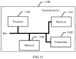
- a structure of the terminal device includes a receiver, a processor, and a transmitter.
- the transmitter and the receiver are configured to: support the terminal device in communicating with a network device; and send information or an instruction related to the foregoing method to the network device, or receive information or an instruction related to the foregoing method from the network device.
- the processor is configured to support the terminal device in executing a corresponding function in the foregoing method.
- the terminal device may further include a memory, configured to store a necessary program and instruction of the network device.
- an embodiment of the present invention further provides a network device, and the network device has functions of implementing operations of the network device in the foregoing method design.
- the functions may be implemented by hardware, or may be implemented by hardware executing corresponding software.
- the hardware or software includes one or more modules corresponding to the foregoing functions.
- a structure of the network device includes a receiver and a transmitter.
- the transmitter and the receiver are configured to: support the network device in communicating with the terminal device; and send information or an instruction related to the foregoing method to the terminal device, or receive information or an instruction related to the foregoing method from the terminal device.
- the network device may further include a memory and a processor, configured to: support the network device in executing a corresponding function in the foregoing method; and store a necessary program and instruction of the network device.
- an embodiment of the present invention further provides a terminal device, and the terminal device has functions of implementing operations of the terminal device in the foregoing method design.
- the functions may be implemented by hardware, or may be implemented by hardware executing corresponding software.
- the hardware or software includes one or more modules corresponding to the foregoing functions.
- the module may be software and/or hardware.
- a structure of the terminal device includes a receiver, a processor, and a transmitter.
- the transmitter and the receiver are configured to: support the terminal device in communicating with a network device; and send information or an instruction related to the foregoing method to the network device, or receive information or an instruction related to the foregoing method from the network device.
- the processor is configured to support the network device in executing a corresponding function in the foregoing method.
- the network device may further include a memory, configured to store a necessary program and instruction of the network device.
- the network device and the terminal device do not need to perform beam scanning and beam training for a formed transmit beam and a formed receive beam respectively.
- the network device receives the channel quality measurement result of the N first reference signals and receives the M second reference signals, so that only the network device needs to perform beam calibration, so as to implement fast beam calibration for the network device and the terminal device, thereby simplifying the beam management process of the terminal device, and maximizing the resource utilization efficiency.
- the embodiments of the present invention provide a signal transmission method, a network device, and a terminal device, so as to implement fast beam calibration for the network device and the terminal device, thereby simplifying a beam management process of the network device or the terminal device, and maximizing resource utilization efficiency.
- the terms “first”, “second”, and the like are intended to distinguish between similar objects but do not necessarily indicate a specific order or sequence. It should be understood that the terms used in such a way are interchangeable in proper circumstances, which is merely a discrimination manner that is used when objects having a same attribute are described in the embodiments of the present invention.
- the terms “include”, “contain” and any other variants mean to cover the non-exclusive inclusion, for example, a process, method, system, product, or device that includes a list of units is not necessarily limited to those units, but may include other units not expressly listed or inherent to such a process, method, system, product, or device.
- FIG. 1 is a schematic diagram of a system architecture to which a signal transmission method according to an embodiment of the present invention is applied.
- the system may include a network device and a terminal device.
- the network device may be specifically a base station, and the terminal device may be specifically a mobile phone, a notebook computer, a tablet computer, or the like.
- the base station may perform downlink transmission to the terminal device.
- the base station sends a synchronization signal sequence to the terminal device.
- the terminal device may perform uplink transmission to the base station.
- Transmission herein may be specifically data transmission and physical layer control signaling transmission.
- a process of interaction between a network device and a terminal device is first described.
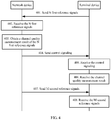
- a signal transmission method provided in an embodiment of the present invention may include the following steps.
- a network device sends N first reference signals to a terminal device, where N is a positive integer greater than or equal to 1.
- the N first reference signals sent by the network device are N downlink reference signals, and a value of N is a positive integer greater than or equal to 1.
- the N downlink reference signals may be N downlink reference signals that are periodically sent, or may be N downlink reference signals that are semi-statically sent, or may be N downlink reference signals that are dynamically and aperiodically sent. This is not limited herein.
- the terminal device receives the N first reference signals sent by the network device, where N is a positive integer greater than or equal to 1.
- the network device may establish a network connection, for example, a wireless network connection, to the terminal device.
- the terminal device receives the N first reference signals sent by the network device.
- the N first reference signals are the N downlink reference signals sent by the network device.
- the terminal device may periodically receive the N downlink reference signals, or may receive the N downlink reference signals that are semi-statically triggered by the network device, or may receive N aperiodic reference signals that are dynamically triggered by the network device. This is not limited herein.
- the network device sends physical layer control signaling to the terminal device, where the physical layer control signaling is used to trigger the terminal device to send a channel quality measurement result of the N first reference signals to the network device, the physical layer control signaling is further used to instruct the terminal device to send M second reference signals to the network device, and M is a positive integer greater than or equal to 1.
- the network device may send the physical layer control signaling to the terminal device.
- the physical layer control signaling generated by the network device may be used to trigger the terminal device to send the channel quality measurement result of the N first reference signals to the network device.
- the physical layer control signaling is further used to instruct the terminal device to send the M second reference signals to the network device.
- the physical layer control signaling sent by the network device may be specifically downlink physical layer control signaling.
- the M second reference signals sent by the terminal device are M uplink reference signals.
- the physical layer control signaling may be used to trigger sending an uplink reference signal for a plurality of times.
- the uplink reference signal may be continuously sent for a plurality of times, or may be not continuously sent for a plurality of times. This is not limited herein.
- transmission bandwidth of the second reference signal is less than or equal to transmission bandwidth of the first reference signal; and/or a frequency domain resource used for transmitting the second reference signal is a subset of a frequency domain resource used for transmitting the first reference signal.
- the first reference signal is sent by the network device, and the second reference signal is sent by the terminal device.
- a signal processing capability of the network device is greater than a signal processing capability of the terminal device. Therefore, transmission bandwidth of the second reference signal is less than or equal to transmission bandwidth of the first reference signal, and a frequency domain resource used for transmitting the second reference signal is a subset of a frequency domain resource used for transmitting the first reference signal.
- the terminal device obtains the channel quality measurement result of the N first reference signals.
- the terminal device receives the N first reference signals sent by the network device.
- the terminal device may perform channel quality measurement on the N first reference signals sent by the network device, and generate the channel quality measurement result of the N first reference signals.
- the channel quality measurement result obtained by the terminal device may include a resource index of one of the N first reference signals.
- the terminal device performs channel quality measurement on the N first reference signals corresponding to N formed beams, selects K (N ⁇ K ⁇ 1) optimal first reference signals, and reports resource indexes of the K optimal first reference signals and corresponding beam channel quality information.
- the beam channel quality information may include at least one of a rank indication (rank indication, RI), channel quality information (channel quality information, CQI), reference signal received power (reference signal received power, RSRP), and reference signal received quality (reference signal received quality, RSRQ).
- the terminal device may select one first reference signal based on channel quality measurement of the N first reference signals, for example, may select a reference signal with best quality in a plurality of first reference signals; and report a resource index of the first reference signal selected by the terminal device and channel quality information corresponding to the resource index of the first reference signal. For example, reporting the resource index and the corresponding channel quality information may be dynamically triggered by physical layer control signaling.
- the resource index of the selected first reference signal may correspond to a transmit beam of the network device.
- the physical layer control signaling used to trigger reporting the resource index of the selected first reference signal and/or the channel quality information corresponding to the index is also used to trigger sending the M (M ⁇ 1) uplink reference signals, and the M uplink reference signals are sent to scan and select an optimal receive beam of the network device.
- the M uplink reference signals may be M uplink reference signals repeatedly sent in a time division mode.
- the physical layer control signaling may be used to trigger sending an uplink reference signal for a plurality of times.
- the uplink reference signal may be continuously sent for a plurality of times, or may be not continuously sent for a plurality of times. This is not limited herein.
- the terminal device receives the physical layer control signaling sent by the network device.
- the physical layer control signaling is used to trigger the terminal device to send the channel quality measurement result of the N first reference signals to the network device, and the physical layer control signaling is further used to instruct the terminal device to send the M second reference signals to the network device, where M is a positive integer greater than or equal to 1.
- the terminal device parses the physical layer control signaling; determines, from the physical layer control signaling, that the terminal device is to send the channel quality measurement result of the N first reference signals to the network device; and determines, from the physical layer control signaling, that the terminal device is to send the M second reference signals to the network device.
- the terminal device sends the channel quality measurement result to the network device.
- the terminal device sends the channel quality measurement result to the network device according to a trigger of the physical layer control signaling.
- the network device receives the channel quality measurement result sent by the terminal device.
- the terminal device sends the channel quality measurement result of the N first reference signals, and the network device receives the channel quality measurement result sent by the terminal device. For example, the network device determines, by using the channel quality measurement result, one first reference signal selected by the terminal device from the N first reference signals.
- the terminal device sends the M second reference signals to the network device.
- the terminal device sends the M second reference signals to the network device according to an instruction of the physical layer control signaling.
- the M second reference signals sent by the terminal device are M uplink reference signals.
- the physical layer control signaling may be used to trigger sending an uplink reference signal for a plurality of times.
- the uplink reference signal may be continuously sent for a plurality of times, or may be not continuously sent for a plurality of times. This is not limited herein.
- step 208 in which the terminal device sends the M second reference signals to the network device includes: repeatedly sending, by the terminal device, the M second reference signals to the network device in a time division mode.
- the terminal device may send the second reference signal in a time division mode.
- the terminal device repeatedly sends the second reference signal to the network device based on a transmit interval, and sends the M second reference signals in total to the network device.
- the moment k for sending the channel quality measurement result according to a trigger of the physical layer control signaling and the moment n for sending the M (M ⁇ 1) uplink reference signals may be the same or may be different.
- a formed transmit beam for the M uplink reference signals is the same as a formed receive beam obtained through measurement, so as to ensure calibration accuracy of an optimal receive beam and an optimal transmit beam on a network device side.
- a value of m may be an integer less than 0.
- the moment for sending the M second reference signals is a moment before the moment for sending the channel quality measurement result of the N first reference signals. No specific limitation is imposed herein.
- a value of m is predefined; or a value of m is indicated to the terminal device by using higher layer signaling or the physical layer control signaling.
- Both the network device and the terminal device may predefine the value of m, or the network device may indicate the value of m to the terminal device by using the higher layer signaling or the physical layer control signaling.
- the higher layer signaling may be specifically Radio Resource Control (radio resource control, RRC) signaling, another higher layer signaling, or the like.
- RRC Radio Resource Control
- the network device receives the M second reference signals sent by the terminal device.
- the terminal device sends the M second reference signals
- the network device receives the M second reference signals sent by the terminal device.
- the network device may receive the M second reference signals that are periodically sent by the terminal device, or may receive the M second reference signals that are semi-statically sent by the terminal device, or may receive the M second reference signals that are dynamically and aperiodically sent by the terminal device. This is not limited herein.
- step 209 in which the network device receives the M second reference signals sent by the terminal device includes: receiving, by the network device, the M second reference signals repeatedly sent by the terminal device in a time division mode. Specifically, the terminal device repeatedly sends the second reference signal, and sends the M second reference signals in total. The network device may receive the second reference signal in a time division mode. The network device repeatedly receives, based on a specific receive interval, the second reference signal sent by the terminal device, and receives the M second reference signals in total sent by the terminal device.
- the network device performs beam calibration based on the received a channel quality measurement result of the N first reference signals and a channel quality measurement result of the M second reference signals.
- an optimal formed beam on the transmit side is the same as an optimal formed beam on the receive side. Therefore, an optimal formed beam on one side can be selected by performing optimal formed beam training and selection on the other side only.
- Measure indicators used to determine whether beam reciprocity stands may include at least one of a signal-to-noise ratio, received signal power corresponding to a beam, received signal quality corresponding to a beam, channel state information (such as CQI) corresponding to a beam, a beam index, or a reference signal index.
- An optimal receive beam may be measured and selected based on a value of at least one of the measure indicators, so as to determine whether the beam reciprocity stands.
- the received signal power corresponding to a beam may be specifically reference signal received power (reference signal received power, RSRP for short), and the received signal quality corresponding to a beam may be reference signal received quality (reference signal received quality, RSRQ for short), or the like.
- the channel state information corresponding to a beam may be CSI information in LTE, for example, at least one of a channel state information-reference signal index (CSI-RS Index, CRI for short), the rank indication (Rank Indication, RI for short), a precoding matrix indication (Precoding Matrix Indicator, PMI for short), or CQI.
- the channel state information corresponding to a beam may be channel quality information of radio resource management (radio resource management, RRM for short) measurement, for example, at least one of RSRP and RSRQ. This embodiment of the present invention imposes no limitation thereto.
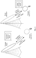
- FIG. 3 is a schematic diagram of a scenario in which a network device completes beam calibration according to an embodiment of the present invention.
- a network device is a base station and a terminal device is UE is used for description.
- a base station side completes calibration of reciprocity between a receive beam and a transmit beam.
- the base station sends N downlink reference signals to the UE by using N different transmit beams, and the UE receives the N downlink reference signals by using N same or different receive beams.
- the UE performs channel quality measurement on the N downlink reference signals, and sends a channel quality measurement result corresponding to a beam to the base station.
- the channel quality measurement result sent by the UE may include a resource index of one of the N downlink reference signals.
- the base station sends physical layer control signaling to the UE, and the UE sends M uplink reference signals to the base station according to trigger information of the physical layer control signaling.
- the base station performs channel quality measurement on the M uplink reference signals, and performs beam calibration based on the received channel quality measurement result of the N downlink reference signals and a channel quality measurement result of the M uplink reference signals.
- a moment k for sending the channel quality measurement result according to a trigger of the physical layer control signaling and a moment n for sending the M (M ⁇ 1) uplink reference signals may be the same or may be different.
- a value of m cannot be arbitrarily large. Otherwise, beam calibration accuracy is affected.
- a formed transmit beam for the M uplink reference signals is the same as a formed receive beam used for receiving the downlink reference signal and obtaining the channel quality measurement result, so as to ensure calibration accuracy of an optimal receive beam and an optimal transmit beam on a network device side.
- a value of m may be an integer less than 0.
- the moment for sending the M uplink reference signals is a moment before the moment for sending the channel quality measurement result of the N downlink reference signals. No specific limitation is imposed herein.
- a reference signal is specifically a sounding reference signal (sounding reference signal, SRS) is used to describe an information bit value of the physical layer control signaling used to trigger sending an uplink reference signal and sending a channel quality measurement result.
- SRS sounding reference signal
- the base station may use separate signaling to trigger sending the channel quality measurement result of the N downlink reference signals and sending the M (M ⁇ 1) uplink reference signals.
- a formed transmit beam for the M uplink reference signal is the same as a formed receive beam used for receiving the downlink reference signals and obtaining a channel quality measurement result.
- the base station needs to simultaneously indicate an association or a correspondence between sending the M uplink reference signals and reporting the channel quality measurement result of the N downlink reference signals, for example, an association between the foregoing sending moment and the foregoing reporting moment, to be specific, an association or a correspondence between the moment for sending the M uplink reference signals and a moment for reporting the channel quality measurement result of the N downlink reference signals.
- the network device may further send the physical layer control signaling to the terminal device.
- the physical layer control signaling is used to trigger the terminal device to send the channel quality measurement result of the N first reference signals to the network device, and the physical layer control signaling is further used to instruct the terminal device to send the M second reference signals to the network device, so that the terminal device may send the channel quality measurement result of the N first reference signals according to the physical layer control signaling, and the terminal device may further send the M second reference signals according to the physical layer control signaling.
- the network device and the terminal device do not need to perform beam scanning and beam training for a formed transmit beam and a formed receive beam respectively.
- the network device receives the channel quality measurement result of the N first reference signals and receives the M second reference signals, so that only the network device needs to perform beam calibration, so as to implement fast beam calibration for the network device and the terminal device, thereby simplifying a beam management process of the terminal device, and maximizing resource utilization efficiency.
- a signal transmission method provided in an embodiment of the present invention may include the following steps.
- a terminal device sends N first reference signals to a network device, where N is a positive integer greater than or equal to 1.
- the N first reference signals sent by the terminal device are N uplink reference signals, and a value of N is a positive integer.
- the N uplink reference signals may be N uplink reference signals that are periodically sent, or may be N uplink reference signals that are semi-statically sent, or may be N uplink reference signals that are dynamically triggered by the network device. This is not limited herein.
- the network device receives the N first reference signals sent by the terminal device, where N is a positive integer greater than or equal to 1.
- the network device may establish a network connection, for example, a wireless network connection, to the terminal device.
- the network device receives the N first reference signals sent by the terminal device.
- the network device obtains a channel quality measurement result of the N first reference signals.
- the network device receives the N first reference signals sent by the terminal device.
- the network device may perform channel quality measurement on the N first reference signals sent by the terminal device, and generate the channel quality measurement result of the N first reference signals.
- the channel quality measurement result includes a resource index of one of the N first reference signals.
- the network device sends physical layer control signaling to the terminal device, where the physical layer control signaling is used to carry the channel quality measurement result of the N first reference signals that is sent by the network device to the terminal device, and N is a positive integer greater than or equal to 1.
- the network device may send the physical layer control signaling to the terminal device.
- the physical layer control signaling generated by the network device may be used to carry the channel quality measurement result of the N first reference signals.
- the physical layer control signaling is further used to instruct the network device to send M second reference signals to the terminal device.
- the terminal device receives the physical layer control signaling sent by the network device, where the physical layer control signaling is used to carry the channel quality measurement result of the N first reference signals that is sent by the network device to the terminal device, and N is a positive integer greater than or equal to 1.
- the terminal device receives the physical layer control signaling sent by the network device; parses the physical layer control signaling; determines, from the physical layer control signaling, that the network device is to send the channel quality measurement result of the N first reference signals; and determines, from the physical layer control signaling, that the network device is to send the M second reference signals to the terminal device.
- the terminal device receives the channel quality measurement result of the N first reference signals.
- the terminal device receives the channel quality measurement result of the N first reference signals according to the physical layer control signaling sent by the network device.
- the network device sends M second reference signals to the terminal device, where sending the M second reference signals by the network device is also triggered by the physical layer control signaling, and M is a positive integer greater than or equal to 1.
- the physical layer control signaling sent by the network device to the terminal device may also be used to trigger the network device to send the channel quality measurement result of the N first reference signals to the terminal device.
- transmission bandwidth of the second reference signal is greater than or equal to transmission bandwidth of the first reference signal; and/or a frequency domain resource used for transmitting the first reference signal is a subset of a frequency domain resource used for transmitting the second reference signal.
- step 407 in which the network device sends M second reference signals to the terminal device includes: repeatedly sending, by the network device, the M second reference signals to the terminal device in a time division mode.
- a value of m is predefined; or a value of m is indicated to the terminal device by using the physical layer control signaling or higher layer signaling.
- a value of m may be an integer less than 0.
- the moment for sending the M second reference signals is a moment before the moment for sending the channel quality measurement result.
- the terminal device receives the M second reference signals sent by the network device, where sending the M second reference signals by the network device is also triggered by the physical layer control signaling.
- the network device sends the M second reference signals to the terminal device, and the terminal device receives the M second reference signals sent by the network device.
- the terminal device may periodically receive the M second reference signals, or may receive the M second reference signals that are semi-statically sent by the network device, or may receive the M second reference signals that are dynamically sent by the network device. This is not limited herein.
- step 408 in which the terminal device receives the M second reference signals sent by the network device includes: receiving, by the terminal device, the M second reference signals repeatedly sent by the network device in a time division mode.
- the signal transmission method provided in this embodiment of the present invention further includes:
- the signal transmission method provided in this embodiment of the present invention further includes: reporting, by the terminal device, a beam calibration result of the terminal device to the network device.
- the signal transmission method provided in this embodiment of the present invention further includes: receiving, by the network device, the beam calibration result of the terminal device reported by the terminal device.
- the network device may receive the beam calibration result of the terminal device by using the terminal device.
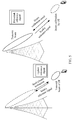
- FIG. 5 is a schematic diagram of a scenario in which a terminal device completes beam calibration according to an embodiment of the present invention.
- a network device is a base station and a terminal device is UE is used for description.
- a UE side completes calibration of reciprocity between a receive beam and a transmit beam.
- the UE sends N uplink reference signals to the base station by using N different transmit beams.
- the base station receives the N uplink reference signals by using N same or different receive beams; performs channel quality measurement on the N uplink reference signals; and sends a channel quality measurement result indication to the UE.
- physical layer control signaling sent by the base station carries a channel quality measurement result of the N uplink reference signals.
- the channel quality measurement result may include a resource index of one of the N uplink reference signals.
- the physical layer control signaling may be any one of a physical-layer downlink control signaling format 0, 1, 2, 2A, 2B, 2C, or 2D of an LTE system.
- the base station sends M downlink reference signals to the UE.
- the UE performs channel quality measurement on the M downlink reference signals; performs beam calibration based on the received channel quality measurement result of the N uplink reference signals and a channel quality measurement result of the M downlink reference signals of the UE; and reports a beam calibration result to the base station.
- the beam calibration result may be indication information used to indicate whether beam reciprocity stands, or may be a quantized value that meets a beam calibration criterion. This is not limited herein.
- An embodiment of the present invention provides a beam calibration method and mechanism of a base station and a UE side, so as to implement fast and accurate beam calibration at a base station end and a UE end by using the mechanism, thereby simplifying a beam management process of the base station or UE, reducing beam scanning, and maximizing resource utilization efficiency.
- calibration of reciprocity between a receive beam and a transmit beam on a UE side is described by using an example.
- the base station may use separate signaling to trigger indication or notification of a channel quality measurement result of N uplink reference signals, and trigger sending M (M ⁇ 1) downlink reference signals.
- M (M ⁇ 1) downlink reference signals a formed transmit beam of the base station for the M (M ⁇ 1) downlink reference signals is the same as a formed receive beam of the base station obtained through measurement based on the channel quality measurement result of the N uplink reference signals.
- the base station needs to simultaneously indicate an association or a correspondence between sending the M downlink reference signals and the channel quality measurement result of the N uplink reference signals, for example, an association relationship between the foregoing sending moment and the foregoing reporting moment, to be specific, an association or a correspondence between a moment for sending the M downlink reference signals and a moment for indicating or notifying the channel quality measurement result of the N uplink reference signals.
- the UE obtains an optimal receive beam based on measurement of the M downlink reference signals, and may determine, by calibrating a difference between the optimal receive beam and an optimal uplink transmit beam notified by the base station, whether reciprocity between a receive beam and a transmit beam on a user side stands.
- the UE reports information about or a result of calibration of the reciprocity between a receive beam and a transmit beam to the base station.
- the information about or the result of the calibration of the reciprocity between a receive beam and a transmit beam may be specifically a 1-bit indication message.
- the indication message includes "yes" or "no"; or may be information about a quantized difference between a receive beam and a transmit beam. This is not limited herein.
- the base station may configure, for the UE, a beam calibration criterion used for calibration of reciprocity between a receive beam and a transmit beam and/or a calibration threshold corresponding to the beam calibration criterion.
- the beam calibration criterion may include at least one of a signal-to-noise ratio, received signal power corresponding to a beam, received signal quality corresponding to a beam, channel quality information (such as CQI) corresponding to a beam, a beam index, or a reference signal index.
- the received signal power corresponding to a beam may be specifically RSRP, and the received signal quality corresponding to a beam may be RSRQ, or the like.
- the channel state information corresponding to a beam may be channel state information CSI (Channel State Information, CSI for short) in LTE.
- the CSI information may include at least one of a CRI, an RI, a PMI, and CQI.
- the channel state information corresponding to a beam may be channel quality information of RRM measurement, for example, at least one of RSRP and RSRQ.
- the channel state information may be any one or more pieces of other channel quality information different from the foregoing information, or may include any one or more pieces of other channel quality information in addition to the foregoing information. This embodiment of the present invention imposes no limitation thereto.
- the embodiments of the present invention provide the beam calibration methods and mechanisms on the base station side and the user side, so as to implement fast and accurate beam calibration at the base station end and the UE end by using the mechanism, thereby simplifying a beam management process of the base station or UE, reducing a delay caused by beam scanning when there is a relatively large quantity of beams, and maximizing resource utilization efficiency.
- the network device may further send the physical layer control signaling to the terminal device.
- the physical layer control signaling is used to trigger the network device to send the channel quality measurement result of the N first reference signals to the terminal device, and the physical layer control signaling is further used to instruct the network device to send the M second reference signals to the terminal device, so that the terminal device may perform beam calibration based on the channel quality measurement result of the N first reference signals that is sent according to the physical layer control signaling and based on a channel quality measurement result of the M second reference signals of the terminal device.
- the network device may also perform corresponding beam calibration based on the foregoing information. Therefore, in this embodiment of the present invention, fast beam calibration for the network device and the terminal device can be implemented, thereby simplifying a beam management process of the network device or the terminal device, and maximizing resource utilization efficiency.
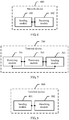
- a network device 600 provided in an embodiment of the present invention may include a sending module 601 and a receiving module 602.
- the sending module 601 is configured to send N first reference signals to a terminal device, where N is a positive integer greater than or equal to 1.
- the sending module 601 is configured to send physical layer control signaling to the terminal device, where the physical layer control signaling is used to trigger the terminal device to send a channel quality measurement result of the N first reference signals to the network device, the physical layer control signaling is further used to instruct the terminal device to send M second reference signals to the network device, and M is a positive integer greater than or equal to 1.
- the receiving module 602 is configured to: after the sending module sends the physical layer control signaling, receive the channel quality measurement result sent by the terminal device; and receive the M second reference signals sent by the terminal device.
- the channel quality measurement result received by the receiving module 602 includes a resource index of one of the N first reference signals.
- a value of m is predefined; or a value of m is indicated to the terminal device by using higher layer signaling or the physical layer control signaling.
- transmission bandwidth of the second reference signal is less than or equal to transmission bandwidth of the first reference signal; and/or a frequency domain resource used for transmitting the second reference signal is a subset of a frequency domain resource used for transmitting the first reference signal.
- the receiving module 602 is specifically configured to receive the M second reference signals repeatedly sent by the terminal device in a time division mode.
- a terminal device 700 provided in an embodiment of the present invention may include a receiving module 701, a processing module 702, and a sending module 703.
- the receiving module 701 is configured to receive N first reference signals sent by a network device, where N is a positive integer greater than or equal to 1.
- the processing module 702 is configured to obtain a channel quality measurement result of the N first reference signals received by the receiving module.
- the receiving module 701 is configured to receive physical layer control signaling sent by the network device, where the physical layer control signaling is used to trigger the terminal device to send the channel quality measurement result of the N first reference signals to the network device, the physical layer control signaling is further used to instruct the terminal device to send M second reference signals to the network device, and M is a positive integer greater than or equal to 1.
- the sending module 703 is configured to: before or after the receiving module receives the physical layer control signaling, send the channel quality measurement result to the network device; and send the M second reference signals to the network device.
- a value of m is predefined; or a value of m is indicated to the terminal device by using higher layer signaling or the physical layer control signaling.
- transmission bandwidth of the second reference signal is less than or equal to transmission bandwidth of the first reference signal; and/or a frequency domain resource used for transmitting the second reference signal is a subset of a frequency domain resource used for transmitting the first reference signal.
- the sending module 703 is specifically configured to repeatedly send the M second reference signals to the network device in a time division mode.
- a terminal device 800 provided in an embodiment of the present invention may include a sending module 801 and a receiving module 802.
- the sending module 801 is configured to send N first reference signals to a network device, where N is a positive integer greater than or equal to 1.
- the receiving module 802 is configured to receive physical layer control signaling sent by the network device, where the physical layer control signaling is used to carry a channel quality measurement result, that is obtained by the network device, and that is of the N first reference signals sent by the sending module.
- the receiving module 802 is configured to: receive the channel quality measurement result of the N first reference signals; and receive M second reference signals sent by the network device, where sending the M second reference signals is also triggered by the physical layer control signaling, and M is a positive integer greater than or equal to 1.
- the channel quality measurement result includes a resource index of one of the N first reference signals.
- a value of m is predefined; or a value of m is indicated to the terminal device by using higher layer signaling or the physical layer control signaling.
- the terminal device further includes a processing module 803.
- the receiving module 802 is configured to receive a beam calibration criterion configured by the network device and/or a calibration threshold corresponding to the beam calibration criterion.
- the processing module 803 is configured to perform beam calibration based on the channel quality measurement result of the N first reference signals that is received by the receiving module and based on a channel quality measurement result of the M second reference signals, by using the beam calibration criterion received by the receiving module and/or the calibration threshold that corresponds to the beam calibration criterion and that is received by the receiving module.
- the sending module 801 is configured to report, to the network device, a result obtained after the processing module performs beam calibration.
- transmission bandwidth of the second reference signal is greater than or equal to transmission bandwidth of the first reference signal; and/or a frequency domain resource used for transmitting the first reference signal is a subset of a frequency domain resource used for transmitting the second reference signal.
- the receiving module 802 is specifically configured to receive the M second reference signals repeatedly sent by the network device in a time division mode.
- a network device 900 provided in an embodiment of the present invention may include a receiving module 901, a processing module 902, and a sending module 903.
- the receiving module 901 is configured to receive N first reference signals sent by a terminal device, where N is a positive integer greater than or equal to 1.
- the processing module 902 is configured to obtain a channel quality measurement result of the N first reference signals received by the receiving module.
- the sending module 903 is configured to send physical layer control signaling to the terminal device, where the physical layer control signaling is used to carry the channel quality measurement result of the N first reference signals that is obtained by the obtaining module.
- the sending module 903 is configured to send M second reference signals to the terminal device, where sending the M second reference signals by the network device is also triggered by the physical layer control signaling, and M is a positive integer greater than or equal to 1.
- a value of m is predefined; or a value of m is indicated to the terminal device by using higher layer signaling or the physical layer control signaling.
- the receiving module 901 is configured to: after the sending module sends the M second reference signals to the terminal device, receive a result that is reported by the terminal device and that is obtained after the terminal device performs beam calibration.
- transmission bandwidth of the second reference signal is greater than or equal to transmission bandwidth of the first reference signal; and/or a frequency domain resource used for transmitting the first reference signal is a subset of a frequency domain resource used for transmitting the second reference signal.
- the sending module 903 is specifically configured to repeatedly send the M second reference signals to the terminal device in a time division mode.
- An embodiment of the present invention further provides a computer storage medium, where the computer storage medium stores a program, and executing the program includes a part or all of the steps described in the foregoing method embodiments.
- a network device 1000 includes: a receiver 1001, a transmitter 1002, a processor 1003, and a memory 1004 (there may be one or more processors 1003 in the network device 1000, and one processor is used as an example in FIG. 10 ).
- the receiver 1001, the transmitter 1002, the processor 1003, and the memory 1004 may be connected by using a bus or in another manner, and the connection by using a bus is used as an example in FIG. 10 .
- the memory 1004 may include a read-only memory and a random access memory, and provide the processor 1003 with an instruction and data. A part of the memory 1004 may further include a nonvolatile random access memory (English full name: Non-Volatile Random Access Memory, NVRAM for short).
- the memory 1004 stores an operating system and an operation instruction, an executable module or a data structure, or a subset thereof, or an extended set thereof.
- the operation instruction may include various operation instructions, so as to implement various operations.
- the operating system may include various system programs, so as to implement various basic services and process hardware-based tasks.
- the processor 1003 controls operations of the network device.
- the processor 1003 may also be referred to as a central processing unit (English full name: Central Processing Unit, CPU for short).
- components of the network device are coupled together by using a bus system.
- the bus system may further include a power bus, a control bus, a status signal bus, and the like.
- various buses are referred to as the bus system in the figure.
- the methods disclosed in the foregoing embodiments of the present invention may be applied to the processor 1003, or implemented by the processor 1003.
- the processor 1003 may be an integrated circuit chip and has a signal processing capability.
- each step of the foregoing method may be completed by using an integrated logical circuit of hardware in the processor 1003 or an instruction in a form of software.
- the processor 1003 may be a general purpose processor, a digital signal processor (English full name: Digital Signal Processing, DSP for short), an application-specific integrated circuit (English full name: Application Specific Integrated Circuit, ASIC for short), a field-programmable gate array (English full name: Field-Programmable Gate Array, FPGA for short) or another programmable logic device, a discrete gate or transistor logic device, or a discrete hardware component. All methods, steps, and logical block diagrams disclosed in this embodiment of the present invention may be implemented or performed.
- the general purpose processor may be a microprocessor or the processor may be any conventional processor, or the like.
- Steps of the methods disclosed in the embodiments of the present invention may be directly performed and completed by a hardware decoding processor, or may be performed and completed by using a combination of hardware in the decoding processor and a software module.
- the software module may be located in a mature storage medium in the field, such as a random access memory, a flash memory, a read-only memory, a programmable read-only memory, an electrically-erasable programmable memory, or a register.
- the storage medium is located in the memory 1004, and the processor 1003 reads information in the memory 1004 and implements the steps of the foregoing method in combination with hardware of the processor 1003.
- the receiver 1001 may be configured to: receive entered digital or character information, and generate signal input related to a related setting and function control of the network device.
- the transmitter 1002 may include a display device such as a display screen, and the transmitter 1002 may be configured to output digital or character information by using an external interface.
- the processor 1003 is configured to execute the signal transmission method performed on a network device side.
- a terminal device 1100 includes: a receiver 1101, a transmitter 1102, a processor 1103, and a memory 1104 (there may be one or more processors 1103 in the terminal device 1100, and one processor is used as an example in FIG. 11 ).
- the receiver 1101, the transmitter 1102, the processor 1103, and the memory 1104 may be connected by using a bus or in another manner, and the connection by using a bus is used as an example in FIG. 11 .
- the memory 1104 may include a read-only memory and a random access memory, and provide the processor 1103 with an instruction and data. A part of the memory 1104 may further include an NVRAM.
- the memory 1104 stores an operating system and an operation instruction, an executable module or a data structure, or a subset thereof, or an extended set thereof.
- the operation instruction may include various operation instructions, so as to implement various operations.
- the operating system may include various system programs, so as to implement various basic services and process hardware-based tasks.
- the processor 1103 controls operations of the terminal device, and the processor 1103 may also be referred to as a CPU.
- components of the terminal device are coupled together by using a bus system.
- the bus system may further include a power bus, a control bus, a status signal bus, and the like.
- various buses are referred to as the bus system in the figure.
- the methods disclosed in the foregoing embodiments of the present invention may be applied to the processor 1103, or implemented by the processor 1103.
- the processor 1103 may be an integrated circuit chip and has a signal processing capability. In an implementation process, each step of the foregoing method may be completed by using an integrated logical circuit of hardware in the processor 1103 or an instruction in a form of software.
- the processor 1103 may be a general purpose processor, a DSP, an ASIC, an FPGA or another programmable logic device, a discrete gate or transistor logic device, or a discrete hardware component. All methods, steps, and logical block diagrams disclosed in this embodiment of the present invention may be implemented or performed.
- the general purpose processor may be a microprocessor or the processor may be any conventional processor, or the like.
- Steps of the methods disclosed in the embodiments of the present invention may be directly performed and completed by a hardware decoding processor, or may be performed and completed by using a combination of hardware in the decoding processor and a software module.
- the software module may be located in a mature storage medium in the field, such as a random access memory, a flash memory, a read-only memory, a programmable read-only memory, an electrically-erasable programmable memory, or a register.
- the storage medium is located in the memory 1104, and the processor 1103 reads information in the memory 1104 and implements the steps of the foregoing method in combination with hardware of the processor 1103.
- the processor 1103 is configured to execute the signal transmission method performed on a terminal device side.
- connection relationships between modules indicate that the modules have communication connections with each other, which may be specifically implemented as one or more communications buses or signal cables.
- the present invention may be implemented by software in addition to necessary universal hardware, or by dedicated hardware, including a dedicated integrated circuit, a dedicated CPU, a dedicated memory, a dedicated component, and the like.
- dedicated hardware including a dedicated integrated circuit, a dedicated CPU, a dedicated memory, a dedicated component, and the like.
- any functions that can be performed by a computer program can be easily implemented by using corresponding hardware.
- a specific hardware structure used to achieve a same function may be of various forms, for example, in a form of an analog circuit, a digital circuit, a dedicated circuit, or the like.
- software program implementation is a better implementation in most cases.
- the technical solutions of the present invention essentially or the part contributing to the prior art may be implemented in a form of a software product.
- the computer software product is stored in a readable storage medium, such as a floppy disk, a USB flash drive, a removable hard disk, a read-only memory (ROM, Read-Only Memory), a random access memory (RAM, Random Access Memory), a magnetic disk, or an optical disc of a computer, and includes several instructions for instructing a computer device (which may be a personal computer, a server, a network device, and the like) to perform the methods described in the embodiments of the present invention.
- a computer device which may be a personal computer, a server, a network device, and the like
Landscapes
- Engineering & Computer Science (AREA)
- Signal Processing (AREA)
- Computer Networks & Wireless Communication (AREA)
- Quality & Reliability (AREA)
- Power Engineering (AREA)
- Mobile Radio Communication Systems (AREA)
Priority Applications (1)
| Application Number | Priority Date | Filing Date | Title |
|---|---|---|---|
| EP25184405.6A EP4648302A3 (de) | 2017-01-06 | 2017-12-18 | Signalübertragungsverfahren, netzwerkvorrichtung und endgerätevorrichtung |
Applications Claiming Priority (2)
| Application Number | Priority Date | Filing Date | Title |
|---|---|---|---|
| CN201710011310.7A CN108282211B (zh) | 2017-01-06 | 2017-01-06 | 一种信号传输方法和网络设备以及终端设备 |
| PCT/CN2017/116912 WO2018126882A1 (zh) | 2017-01-06 | 2017-12-18 | 一种信号传输方法和网络设备以及终端设备 |
Related Child Applications (2)
| Application Number | Title | Priority Date | Filing Date |
|---|---|---|---|
| EP25184405.6A Division EP4648302A3 (de) | 2017-01-06 | 2017-12-18 | Signalübertragungsverfahren, netzwerkvorrichtung und endgerätevorrichtung |
| EP25184405.6A Division-Into EP4648302A3 (de) | 2017-01-06 | 2017-12-18 | Signalübertragungsverfahren, netzwerkvorrichtung und endgerätevorrichtung |
Publications (3)
| Publication Number | Publication Date |
|---|---|
| EP3553964A1 true EP3553964A1 (de) | 2019-10-16 |
| EP3553964A4 EP3553964A4 (de) | 2019-12-25 |
| EP3553964B1 EP3553964B1 (de) | 2025-08-13 |
Family
ID=62788943
Family Applications (2)
| Application Number | Title | Priority Date | Filing Date |
|---|---|---|---|
| EP25184405.6A Pending EP4648302A3 (de) | 2017-01-06 | 2017-12-18 | Signalübertragungsverfahren, netzwerkvorrichtung und endgerätevorrichtung |
| EP17889615.5A Active EP3553964B1 (de) | 2017-01-06 | 2017-12-18 | Signalübertragungsverfahren, netzwerkvorrichtung und endgerätevorrichtung |
Family Applications Before (1)
| Application Number | Title | Priority Date | Filing Date |
|---|---|---|---|
| EP25184405.6A Pending EP4648302A3 (de) | 2017-01-06 | 2017-12-18 | Signalübertragungsverfahren, netzwerkvorrichtung und endgerätevorrichtung |
Country Status (5)
| Country | Link |
|---|---|
| US (1) | US10979193B2 (de) |
| EP (2) | EP4648302A3 (de) |
| CN (4) | CN110233655B (de) |
| CA (1) | CA3048933C (de) |
| WO (1) | WO2018126882A1 (de) |
Families Citing this family (14)
| Publication number | Priority date | Publication date | Assignee | Title |
|---|---|---|---|---|
| KR102518403B1 (ko) * | 2018-07-09 | 2023-04-06 | 삼성전자주식회사 | 외부 전자 장치의 상태를 확인하기 위한 장치 및 방법 |
| US10887884B2 (en) * | 2018-09-21 | 2021-01-05 | Samsung Electronics Co., Ltd. | Method and apparatus for signaling in support of uplink multi-beam operation |
| CN111355627B (zh) * | 2018-12-24 | 2022-08-26 | 成都华为技术有限公司 | 资源上报的方法及装置 |
| WO2020167890A1 (en) * | 2019-02-15 | 2020-08-20 | Sony Corporation | Methods and devices for coordinated uplink-based positioning |
| CN111698007B (zh) * | 2019-03-15 | 2021-04-16 | 大唐移动通信设备有限公司 | 一种基于混合波束赋形架构的校准补偿方法及装置 |
| US12489505B2 (en) | 2020-03-06 | 2025-12-02 | Nokia Technologies Oy | Improving precoding |
| US11683757B2 (en) * | 2020-06-22 | 2023-06-20 | Qualcomm Incorporated | Leveraging wake-up signals and discontinuous reception cycles for assisted antenna calibration |
| US11751186B2 (en) * | 2020-07-21 | 2023-09-05 | Qualcomm Incorporated | Single layer uplink non-codebook based precoding optimization |
| CN114915320A (zh) * | 2021-02-10 | 2022-08-16 | 华为技术有限公司 | 一种波束管理方法及装置 |
| AU2022334070B2 (en) * | 2021-08-24 | 2025-04-03 | Huawei Technologies Co., Ltd. | Location determining method and apparatus |
| US20230353309A1 (en) * | 2022-04-29 | 2023-11-02 | Qualcomm Incorporated | Methods for using two-way beamforming operations for calibration |
| WO2024000591A1 (zh) * | 2022-07-01 | 2024-01-04 | Oppo广东移动通信有限公司 | 无线通信方法和通信设备 |
| US12362839B2 (en) * | 2022-10-27 | 2025-07-15 | Qualcomm Incorporated | Online calibration with phase or signal strength measurements |
| CN117042135A (zh) * | 2023-06-30 | 2023-11-10 | 华为技术有限公司 | 通信方法及装置 |
Family Cites Families (22)
| Publication number | Priority date | Publication date | Assignee | Title |
|---|---|---|---|---|
| US8798183B2 (en) * | 2007-08-13 | 2014-08-05 | Qualcomm Incorporated | Feedback and rate adaptation for MIMO transmission in a time division duplexed (TDD) communication system |
| US20090093222A1 (en) * | 2007-10-03 | 2009-04-09 | Qualcomm Incorporated | Calibration and beamforming in a wireless communication system |
| CN107070622B (zh) * | 2009-06-02 | 2021-02-09 | 太阳专利信托公司 | 终端装置、通信装置、通信方法和集成电路 |
| JP5538930B2 (ja) | 2010-02-04 | 2014-07-02 | シャープ株式会社 | 移動局装置、基地局装置、無線通信システムおよび無線通信方法 |
| CN102170330B (zh) * | 2011-04-29 | 2017-08-08 | 中兴通讯股份有限公司 | 测量参考信号的发送方法及系统 |
| CN102291189B (zh) * | 2011-08-12 | 2016-03-23 | 电信科学技术研究院 | 天线校准方法和设备 |
| CN102546110A (zh) * | 2011-12-31 | 2012-07-04 | 电信科学技术研究院 | 一种传输信道状态信息的方法及装置 |
| CN103259581B (zh) | 2012-02-16 | 2016-08-03 | 电信科学技术研究院 | 一种进行天线校准的方法、系统和设备 |
| US9392639B2 (en) * | 2013-02-27 | 2016-07-12 | Samsung Electronics Co., Ltd. | Methods and apparatus for channel sounding in beamformed massive MIMO systems |
| CN105052047B (zh) * | 2013-03-11 | 2018-12-14 | Lg 电子株式会社 | 在无线通信系统中报告信道状态信息的方法和装置 |
| KR102085003B1 (ko) * | 2013-04-30 | 2020-04-14 | 삼성전자주식회사 | 빔포밍 시스템에서 최적의 송수신 빔 제공 방법 및 장치 |
| WO2015080648A1 (en) * | 2013-11-27 | 2015-06-04 | Telefonaktiebolaget L M Ericsson (Publ) | Methods for receiving and sending a report comprising channel state information |
| CN104202073A (zh) * | 2014-03-04 | 2014-12-10 | 中兴通讯股份有限公司 | 信道信息的反馈方法、导频及波束发送方法、系统及装置 |
| US20170093506A1 (en) * | 2014-06-12 | 2017-03-30 | Nokia Solutions and Technologies Oy | Method, apparatus and computer program |
| US10355761B2 (en) * | 2014-10-07 | 2019-07-16 | Mediatek Inc. | Beam administration methods for cellular/wireless networks |
| US10306597B2 (en) * | 2015-07-21 | 2019-05-28 | Samsung Electronics Co., Ltd. | Method and apparatus for beam-level radio resource management and mobility in cellular network |
| WO2017176022A1 (en) * | 2016-04-04 | 2017-10-12 | Samsung Electronics Co., Ltd. | Method and apparatus for managing beam in beamforming system |
| US10141999B2 (en) * | 2016-05-27 | 2018-11-27 | Telefonaktiebolaget Lm Ericsson (Publ) | Reference signal tracking in a wireless communication system |
| KR102185482B1 (ko) * | 2016-06-17 | 2020-12-03 | 노키아 테크놀로지스 오와이 | 대규모 mimo 시스템을 위한 강화된 업링크 빔 선택 |
| EP3494746B1 (de) * | 2016-08-12 | 2023-03-01 | Mediatek Inc. | Strahlverwaltung in strahlformungssystemen |
| WO2018064327A1 (en) * | 2016-09-28 | 2018-04-05 | Idac Holdings, Inc. | Systems and methods for beam management |
| US10680689B2 (en) * | 2017-01-05 | 2020-06-09 | Futurewei Technologies, Inc. | Beam management techniques for beam calibration |
-
2017
- 2017-01-06 CN CN201910472348.3A patent/CN110233655B/zh active Active
- 2017-01-06 CN CN201910470117.9A patent/CN110278016B/zh active Active
- 2017-01-06 CN CN201710011310.7A patent/CN108282211B/zh active Active
- 2017-12-18 CA CA3048933A patent/CA3048933C/en active Active
- 2017-12-18 WO PCT/CN2017/116912 patent/WO2018126882A1/zh not_active Ceased
- 2017-12-18 EP EP25184405.6A patent/EP4648302A3/de active Pending
- 2017-12-18 CN CN201780079857.9A patent/CN110100395B/zh active Active
- 2017-12-18 EP EP17889615.5A patent/EP3553964B1/de active Active
-
2019
- 2019-07-03 US US16/502,956 patent/US10979193B2/en active Active
Also Published As
| Publication number | Publication date |
|---|---|
| US20190327060A1 (en) | 2019-10-24 |
| EP4648302A2 (de) | 2025-11-12 |
| CN108282211A (zh) | 2018-07-13 |
| CA3048933C (en) | 2023-02-28 |
| CN110278016A (zh) | 2019-09-24 |
| BR112019014034A2 (pt) | 2020-02-04 |
| CN110100395B (zh) | 2021-09-07 |
| CN108282211B (zh) | 2023-11-03 |
| CN110233655A (zh) | 2019-09-13 |
| WO2018126882A1 (zh) | 2018-07-12 |
| EP3553964B1 (de) | 2025-08-13 |
| CN110278016B (zh) | 2020-07-24 |
| EP4648302A3 (de) | 2025-12-24 |
| CA3048933A1 (en) | 2018-07-12 |
| US10979193B2 (en) | 2021-04-13 |
| CN110233655B (zh) | 2020-10-27 |
| EP3553964A4 (de) | 2019-12-25 |
| CN110100395A (zh) | 2019-08-06 |
Similar Documents
| Publication | Publication Date | Title |
|---|---|---|
| US10979193B2 (en) | Signal transmission method, network device, and terminal device | |
| US11870525B2 (en) | Channel measurement configuration method and communications apparatus | |
| US11405163B2 (en) | Channel quality information reporting method, terminal device, and network device | |
| US11497030B2 (en) | Channel quality information reporting method and apparatus | |
| CN112583462B (zh) | 用于报告信号质量信息的系统和方法 | |
| US20210306185A1 (en) | Method for determining transmission parameters of uplink signal, terminal and network device | |
| US10716025B2 (en) | Communication method, terminal, and base station | |
| EP3910849B1 (de) | Verfahren und vorrichtung zur kanal- und interferenzmessung | |
| US11006410B2 (en) | Method and apparatus for transmitting uplink information | |
| EP4224768A1 (de) | Verfahren und vorrichtung zur bestimmung von uplink-kanalparametern sowie verfahren und vorrichtung zur konfiguration von uplink-kanalparametern | |
| WO2019100905A1 (zh) | 数据传输方法、终端设备和网络设备 | |
| EP4224934A1 (de) | Verfahren und vorrichtung zur strahlumschaltung | |
| EP3913960A1 (de) | Kommunikationsverfahren und -vorrichtung | |
| US20230110955A1 (en) | Apparatus and method for assistance information transmission and csi reporting | |
| EP3668160B1 (de) | Signalmeldeverfahren und endgerätevorrichtung | |
| US20240313930A1 (en) | Trigger state configuration and csi report triggering for dynamic spectrum sharing (dss) with carrier aggregation (ca) | |
| BR112019014034B1 (pt) | Método de transmissão de sinal, dispositivo de rede e dispositivo terminal | |
| CN113873666A (zh) | 数据调度方法、装置及计算机可读存储介质 |
Legal Events
| Date | Code | Title | Description |
|---|---|---|---|
| STAA | Information on the status of an ep patent application or granted ep patent |
Free format text: STATUS: THE INTERNATIONAL PUBLICATION HAS BEEN MADE |
|
| PUAI | Public reference made under article 153(3) epc to a published international application that has entered the european phase |
Free format text: ORIGINAL CODE: 0009012 |
|
| STAA | Information on the status of an ep patent application or granted ep patent |
Free format text: STATUS: REQUEST FOR EXAMINATION WAS MADE |
|
| 17P | Request for examination filed |
Effective date: 20190708 |
|
| AK | Designated contracting states |
Kind code of ref document: A1 Designated state(s): AL AT BE BG CH CY CZ DE DK EE ES FI FR GB GR HR HU IE IS IT LI LT LU LV MC MK MT NL NO PL PT RO RS SE SI SK SM TR |
|
| AX | Request for extension of the european patent |
Extension state: BA ME |
|
| A4 | Supplementary search report drawn up and despatched |
Effective date: 20191126 |
|
| RIC1 | Information provided on ipc code assigned before grant |
Ipc: H04B 7/06 20060101AFI20191120BHEP Ipc: H04B 7/08 20060101ALI20191120BHEP Ipc: H04L 1/00 20060101ALI20191120BHEP Ipc: H04L 25/03 20060101ALI20191120BHEP Ipc: H04B 7/0417 20170101ALI20191120BHEP |
|
| DAV | Request for validation of the european patent (deleted) | ||
| DAX | Request for extension of the european patent (deleted) | ||
| STAA | Information on the status of an ep patent application or granted ep patent |
Free format text: STATUS: EXAMINATION IS IN PROGRESS |
|
| 17Q | First examination report despatched |
Effective date: 20211213 |
|
| GRAP | Despatch of communication of intention to grant a patent |
Free format text: ORIGINAL CODE: EPIDOSNIGR1 |
|
| STAA | Information on the status of an ep patent application or granted ep patent |
Free format text: STATUS: GRANT OF PATENT IS INTENDED |
|
| INTG | Intention to grant announced |
Effective date: 20240730 |
|
| GRAJ | Information related to disapproval of communication of intention to grant by the applicant or resumption of examination proceedings by the epo deleted |
Free format text: ORIGINAL CODE: EPIDOSDIGR1 |
|
| STAA | Information on the status of an ep patent application or granted ep patent |
Free format text: STATUS: EXAMINATION IS IN PROGRESS |
|
| INTC | Intention to grant announced (deleted) | ||
| GRAP | Despatch of communication of intention to grant a patent |
Free format text: ORIGINAL CODE: EPIDOSNIGR1 |
|
| STAA | Information on the status of an ep patent application or granted ep patent |
Free format text: STATUS: GRANT OF PATENT IS INTENDED |
|
| INTG | Intention to grant announced |
Effective date: 20250317 |
|
| GRAS | Grant fee paid |
Free format text: ORIGINAL CODE: EPIDOSNIGR3 |
|
| GRAA | (expected) grant |
Free format text: ORIGINAL CODE: 0009210 |
|
| STAA | Information on the status of an ep patent application or granted ep patent |
Free format text: STATUS: THE PATENT HAS BEEN GRANTED |
|
| AK | Designated contracting states |
Kind code of ref document: B1 Designated state(s): AL AT BE BG CH CY CZ DE DK EE ES FI FR GB GR HR HU IE IS IT LI LT LU LV MC MK MT NL NO PL PT RO RS SE SI SK SM TR |
|
| REG | Reference to a national code |
Ref country code: GB Ref legal event code: FG4D |
|
| REG | Reference to a national code |
Ref country code: CH Ref legal event code: EP |
|
| REG | Reference to a national code |
Ref country code: DE Ref legal event code: R096 Ref document number: 602017091239 Country of ref document: DE |
|
| REG | Reference to a national code |
Ref country code: IE Ref legal event code: FG4D |
|
| REG | Reference to a national code |
Ref country code: NL Ref legal event code: MP Effective date: 20250813 |
|
| PG25 | Lapsed in a contracting state [announced via postgrant information from national office to epo] |
Ref country code: IS Free format text: LAPSE BECAUSE OF FAILURE TO SUBMIT A TRANSLATION OF THE DESCRIPTION OR TO PAY THE FEE WITHIN THE PRESCRIBED TIME-LIMIT Effective date: 20251213 |
|
| PGFP | Annual fee paid to national office [announced via postgrant information from national office to epo] |
Ref country code: DE Payment date: 20251104 Year of fee payment: 9 |
|
| PGFP | Annual fee paid to national office [announced via postgrant information from national office to epo] |
Ref country code: GB Payment date: 20251030 Year of fee payment: 9 |
|
| PG25 | Lapsed in a contracting state [announced via postgrant information from national office to epo] |
Ref country code: NO Free format text: LAPSE BECAUSE OF FAILURE TO SUBMIT A TRANSLATION OF THE DESCRIPTION OR TO PAY THE FEE WITHIN THE PRESCRIBED TIME-LIMIT Effective date: 20251113 |
|
| REG | Reference to a national code |
Ref country code: LT Ref legal event code: MG9D |
|
| PG25 | Lapsed in a contracting state [announced via postgrant information from national office to epo] |
Ref country code: PT Free format text: LAPSE BECAUSE OF FAILURE TO SUBMIT A TRANSLATION OF THE DESCRIPTION OR TO PAY THE FEE WITHIN THE PRESCRIBED TIME-LIMIT Effective date: 20251215 |
|
| PG25 | Lapsed in a contracting state [announced via postgrant information from national office to epo] |
Ref country code: FI Free format text: LAPSE BECAUSE OF FAILURE TO SUBMIT A TRANSLATION OF THE DESCRIPTION OR TO PAY THE FEE WITHIN THE PRESCRIBED TIME-LIMIT Effective date: 20250813 |
|
| PG25 | Lapsed in a contracting state [announced via postgrant information from national office to epo] |
Ref country code: NL Free format text: LAPSE BECAUSE OF FAILURE TO SUBMIT A TRANSLATION OF THE DESCRIPTION OR TO PAY THE FEE WITHIN THE PRESCRIBED TIME-LIMIT Effective date: 20250813 Ref country code: HR Free format text: LAPSE BECAUSE OF FAILURE TO SUBMIT A TRANSLATION OF THE DESCRIPTION OR TO PAY THE FEE WITHIN THE PRESCRIBED TIME-LIMIT Effective date: 20250813 |
|
| PG25 | Lapsed in a contracting state [announced via postgrant information from national office to epo] |
Ref country code: GR Free format text: LAPSE BECAUSE OF FAILURE TO SUBMIT A TRANSLATION OF THE DESCRIPTION OR TO PAY THE FEE WITHIN THE PRESCRIBED TIME-LIMIT Effective date: 20251114 |
|
| PG25 | Lapsed in a contracting state [announced via postgrant information from national office to epo] |
Ref country code: SE Free format text: LAPSE BECAUSE OF FAILURE TO SUBMIT A TRANSLATION OF THE DESCRIPTION OR TO PAY THE FEE WITHIN THE PRESCRIBED TIME-LIMIT Effective date: 20250813 |
|
| PG25 | Lapsed in a contracting state [announced via postgrant information from national office to epo] |
Ref country code: LV Free format text: LAPSE BECAUSE OF FAILURE TO SUBMIT A TRANSLATION OF THE DESCRIPTION OR TO PAY THE FEE WITHIN THE PRESCRIBED TIME-LIMIT Effective date: 20250813 |
|
| PG25 | Lapsed in a contracting state [announced via postgrant information from national office to epo] |
Ref country code: BG Free format text: LAPSE BECAUSE OF FAILURE TO SUBMIT A TRANSLATION OF THE DESCRIPTION OR TO PAY THE FEE WITHIN THE PRESCRIBED TIME-LIMIT Effective date: 20250813 Ref country code: PL Free format text: LAPSE BECAUSE OF FAILURE TO SUBMIT A TRANSLATION OF THE DESCRIPTION OR TO PAY THE FEE WITHIN THE PRESCRIBED TIME-LIMIT Effective date: 20250813 |
|
| PG25 | Lapsed in a contracting state [announced via postgrant information from national office to epo] |
Ref country code: RS Free format text: LAPSE BECAUSE OF FAILURE TO SUBMIT A TRANSLATION OF THE DESCRIPTION OR TO PAY THE FEE WITHIN THE PRESCRIBED TIME-LIMIT Effective date: 20251113 |
|
| PG25 | Lapsed in a contracting state [announced via postgrant information from national office to epo] |
Ref country code: ES Free format text: LAPSE BECAUSE OF FAILURE TO SUBMIT A TRANSLATION OF THE DESCRIPTION OR TO PAY THE FEE WITHIN THE PRESCRIBED TIME-LIMIT Effective date: 20250813 |