EP3553957B1 - System und verfahren zur sicherung eines wifi-netzwerks - Google Patents
System und verfahren zur sicherung eines wifi-netzwerks Download PDFInfo
- Publication number
- EP3553957B1 EP3553957B1 EP19168165.9A EP19168165A EP3553957B1 EP 3553957 B1 EP3553957 B1 EP 3553957B1 EP 19168165 A EP19168165 A EP 19168165A EP 3553957 B1 EP3553957 B1 EP 3553957B1
- Authority
- EP
- European Patent Office
- Prior art keywords
- module
- network
- communication
- control module
- authentication key
- Prior art date
- Legal status (The legal status is an assumption and is not a legal conclusion. Google has not performed a legal analysis and makes no representation as to the accuracy of the status listed.)
- Active
Links
Images

Classifications
-
- H—ELECTRICITY
- H04—ELECTRIC COMMUNICATION TECHNIQUE
- H04W—WIRELESS COMMUNICATION NETWORKS
- H04W12/00—Security arrangements; Authentication; Protecting privacy or anonymity
- H04W12/06—Authentication
-
- H—ELECTRICITY
- H04—ELECTRIC COMMUNICATION TECHNIQUE
- H04B—TRANSMISSION
- H04B3/00—Line transmission systems
- H04B3/54—Systems for transmission via power distribution lines
-
- H—ELECTRICITY
- H04—ELECTRIC COMMUNICATION TECHNIQUE
- H04W—WIRELESS COMMUNICATION NETWORKS
- H04W12/00—Security arrangements; Authentication; Protecting privacy or anonymity
- H04W12/04—Key management, e.g. using generic bootstrapping architecture [GBA]
-
- H—ELECTRICITY
- H04—ELECTRIC COMMUNICATION TECHNIQUE
- H04B—TRANSMISSION
- H04B2203/00—Indexing scheme relating to line transmission systems
- H04B2203/54—Aspects of powerline communications not already covered by H04B3/54 and its subgroups
- H04B2203/5462—Systems for power line communications
- H04B2203/547—Systems for power line communications via DC power distribution
-
- H—ELECTRICITY
- H04—ELECTRIC COMMUNICATION TECHNIQUE
- H04B—TRANSMISSION
- H04B3/00—Line transmission systems
- H04B3/54—Systems for transmission via power distribution lines
- H04B3/548—Systems for transmission via power distribution lines the power on the line being DC
Definitions
- the present invention relates to securing wireless communication between components and, in particular, utilizing a power line communication to transmit a Wi-Fi network authentication key to secure a Wi-Fi network that is used for communication between components in a system.
- Communication between components in a system is generally performed via communication wires that extend between the components.
- Such wires are heavy, take up precious space, are time consuming to install, and are prone to damage that can cause interference to the communication.
- systems that use wireless communication reduce the need to use communication wires, these systems are prone to cyber-attacks and thus their use is avoided within certain systems, such as communication systems on sensitive vehicles (e.g., aircraft and military vehicles) or automated assembly lines.
- US 2016/203310 A1 and US 2010/146277 A1 each disclose a system for securing a Wi-Fi network.
- a system for securing a Wi-Fi network includes a power source that transmits an electric current along at least one power line, a power line communication (PLC) module in electrical communication with the power source via the at least one power line with the PLC module being configured to modulate the electric current to include a power line communication that contains a Wi-Fi network authentication key, a control module in electrical communication with and electrically downstream from the PLC module via the at least one power line with the control module being configured to extract the power line communication from the electric current and utilize the Wi-Fi network authentication key to access the Wi-Fi network, a master module in communication with the control module, the master module being configured to communicate instructions to the control module via the Wi-Fi network, and a first mechanism, the first mechanism being in communication with the control module, wherein the control module instructs the first mechanism to perform a function depending on the instructions from the master module, wherein the first mechanism is connected to the control module by a wired communication line and wherein extracting the power line communication from the electric current includes demodulating the electric current to separate the
- a method of securing a Wi-Fi network includes modulating an electric current using a PLC module to include a power line communication that contains a Wi-Fi network authentication key, conveying the electric current with the power line communication along a power line, demodulating the electric current using a control module to extract the power line communication that contains the Wi-Fi network authentication key, utilizing the Wi-Fi network authentication key to access the Wi-Fi network, communicating instructions to the control module via the Wi-Fi network; and instructing a first mechanism to perform a function, depending on the instructions, wherein the first mechanism is connected to the control module by a wired communication line, and wherein the PLC module and the master module are separate components, which are distant from one another.
- a system for securing a Wi-Fi network on a vehicle utilizes a power line communication (hereinafter, "PLC") to transmit a Wi-Fi network authentication key along a power line to be extracted and utilized to connect to the Wi-Fi network.
- PLC power line communication
- the PLC is transmitted as signal modulation (e.g., frequency or pulse) of an electric current.
- the electric current is modulated to include the PLC (which in turn contains the Wi-Fi network authentication key) by a PLC module in electrical communication with the power source via the power line, while the PLC containing the Wi-Fi network authentication key can be extracted by a control module in electrical communication with the PLC module via the power line.
- the control module utilizes the Wi-Fi network authentication key to access the Wi-Fi network to send and receive data and/or instructions from a master module and/or other components.
- the control module can be part of or in communication with one or a number of mechanisms, such as actuators and sensors, that perform the instructions sent to the control module by the master module and/or record data that is then transmitted via the Wi-Fi network by the control module to the master control.
- the Wi-Fi network authentication key is only transmitted via the PLC in the electric current along the power line, only components in electrical communication with the PLC module (components along the power line downstream from the PLC module) are able to receive and extract the Wi-Fi network authentication key to gain access to the Wi-Fi network, thus providing a secure network accessible only by components on the power line (i.e., by components on the power grid).
- the PLC can be periodically altered to update the Wi-Fi network authentication key such that access to the Wi-Fi network is regularly changed for additional security, such as generating a new Wi-Fi authentication key periodically and requiring the control module to reestablish authentication to the Wi-Fi network at regular intervals.
- the present disclosure describes the system for securing the Wi-Fi network that can be utilized on a vehicle, such as an aircraft, or within a ground-based system, such as to secure a Wi-Fi network utilized for communication between components (e.g., robots) on an assembly line (or in another configuration) or to secure communication between computers and/or mobile devices in a large system.
- a vehicle such as an aircraft
- a ground-based system such as to secure a Wi-Fi network utilized for communication between components (e.g., robots) on an assembly line (or in another configuration) or to secure communication between computers and/or mobile devices in a large system.
- FIG. 1A is a schematic of a system using power line communication to secure a Wi-Fi network
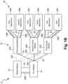
- FIG. 1B is an enlarged schematic of a portion of the system showing mechanisms in communication with control modules.
- System 10 includes power source 12, power conditioner 14, power distributor 16, PLC module 18, control modules 20 (first control module 20A, second control module 20B, and third control module 20C), master module 22, power lines 24, wireless communication lines 26A, wired communication lines 26B, and mechanisms 28 (first mechanism 28A, second mechanism 28B, third mechanism 28C, fourth mechanism 28D, fifth mechanism 28E, and sixth mechanism 28F).
- System 10 can be located on a vehicle, such as an aircraft, and includes various components needed to ensure the vehicle is able to function for the vehicle's intended purpose.
- power source 12 provides power to the components of system 10 via power lines 24.
- Power source 12 can be a battery, an engine, or any other type or combination of power generation and/or storage system configured to provide an electric current along power lines 24 to drive the components of system 10.
- Power source 12, power conditioner 14, power distributor 16, PLC module 18, and/or master module 22 can all be one component configured to perform the various tasks or multiple components in electrical communication with power source 12 (i.e., along power lines 24 as shown in the disclosed embodiment).
- Power lines 24 are electrical wires configured to transmit the electric current between components.
- power lines 24 can be any type of cables/wires/lines configured to transmit any type of current, voltage, amperes, etc.
- Power conditioner 14 is in electrical communication with power source 12 via power lines 24. Power conditioner 14 is configured to condition the electric current to be the necessary current (i.e., alternating or direct), voltage, etc. that are suitable for use by the other components of system 10.
- Power distributor 16 is in electrical communication with power source 12 via power lines 24 downstream from power source 12. Power distributor 16 distributes/directs the electric current to the necessary components of system 10. Power distributor 16 can direct the electric current to one or multiple components of system 10, including components that do not require the Wi-Fi authentication key (or components in which access to the Wi-Fi network would not be desirable, such as electrical outlets within a passenger cabin of an aircraft). However, power distributor 16 should direct at least a portion of the electric current to PLC module 18 and then on to control modules 20 (which receive the electric current and extract the PLC containing the Wi-Fi authentication key that is added to the electric current by PLC module 18). The electric current directed to PLC module 18 and control modules 20 also provides power to drive those components.
- PLC module 18 is in electrical communication with power source 12 via power lines 24 downstream from power source 12.
- PLC module is configured to modulate the electric current to include the PLC, which contains the Wi-Fi network authentication key, to communicate data along power lines 24.
- the PLC can consist entirely of the Wi-Fi network authentication key or can include other data.
- the PLC transmitted along the power lines 24 to control modules 20 can be any type of PLC, including narrowband or broadband PLC.
- the electric current that is modulated by PLC module 18 to include the PLC can be alternating current or direct current.
- PLC module 18 can use a variety of modulation schemes to add the PLC to the electric current, such as Orthogonal Frequency Division Multiplexing, Binary Phase Shift Keying, Frequency Shift Keying, Spread Frequency Shift Keying, Differential Code Shift Keying, or another type of scheme. Additionally, the PLC can be configured to function at a variety of frequencies suitable to communicate the Wi-Fi authentication key along power lines 24. PLC module 18 can be in communication with master module 22 via wireless communication lines 26A or wireless communication lines 26B, with master module 22 communicating information about the Wi-Fi authentication key so that PLC module 18 can include that data in the PLC.
- modulation schemes such as Orthogonal Frequency Division Multiplexing, Binary Phase Shift Keying, Frequency Shift Keying, Spread Frequency Shift Keying, Differential Code Shift Keying, or another type of scheme.
- the PLC can be configured to function at a variety of frequencies suitable to communicate the Wi-Fi authentication key along power lines 24.
- PLC module 18 can periodically create a different Wi-Fi authentication key that is included in the PLC and communicate that information (i.e., the Wi-Fi authentication key) to master module 22, with master module 22 utilizing the Wi-Fi authentication key to access the Wi-Fi network and communicate with control modules 20.
- PLC module 18 and master module 22 communicate via wired communication line 26B.
- Control modules 20 are in electrical communication with power source 12 via power lines 24 (control modules 20 may be along the same power line 24 or different power lines 24) and are downstream from power source 12 and PLC module 18.
- System 10 can include any number of control modules 20, including one, two, or more than three.
- Control modules 20 are each configured to extract the PLC from the electric current flowing through power lines 24 and utilize the Wi-Fi network authentication key (that is contained in the PLC) to access the Wi-Fi network. After gaining access to the Wi-Fi network, control modules 20 can send and receive instructions, data, and other communications to and from other components with access to the Wi-Fi network, such as master module 22.
- control modules 20 are configured to receive instructions from master module 22 and convey those instructions to mechanisms 28 while also receiving data and other information from mechanisms 28 and conveying that information to master module 22.
- Control modules 20 can be configured to continuously demodulate the PLC to extract and utilize different Wi-Fi authentication keys that are periodically updated/created to access the Wi-Fi network to provide additional security to the Wi-Fi network.
- Master module 22 is in communication with control modules 20 and PLC module 18 via wireless communication lines 26A and/or wired communication lines 26B. Master module 22 can be configured to communicate instructions and other information to control modules 20 via the Wi-Fi network. Master module 22 can be configured to communicate information about the Wi-Fi authentication key so that PLC module 18 can include that data in the PLC, which is then transmitted to control modules 20 via power lines 24. Master module 22 can also be configured to receive data and other information from control modules 22 and/or convey that information to other components in system 10, such as a display panel. PLC module 18 and master module 22 can be one component configured to perform the various tasks or two or more components distant from one another. Additionally, PLC module 18 and/or master module 22 can be part of a vehicle engine control unit (ECU), full authority digital engine/electronics control (FADEC), or another vehicle electronics unit.
- ECU vehicle engine control unit
- FADEC full authority digital engine/electronics control
- Wireless communication lines 26A allow for some components of system 10 to communicate with one another without the need for wired communication lines 26B.
- wireless communication lines 26A are the Wi-Fi network that is utilized for wireless communication and are not "lines" (i.e., wires) that transfer electric current for power and/or communication.
- master module 22 communicates with control modules 20 wirelessly via the Wi-Fi network.
- Wired communication lines 26B allow for some components of system 10 to communicate with one another via the use of wires. Wired communication lines 26B do not require the components communicating via wired communication lines 26B to have access to the Wi-Fi network (and thus do not require the ability to receive and demodulate the PLC to obtain and utilize the Wi-Fi network authentication key).
- PLC module 18 and master module 22 communicate with one another via wired communication lines 26B (alternately, the two components can be adjacent to one another or can be one component that is configured to perform all of the tasks of both PLC module 18 and master module 22).
- control modules 20 and mechanisms 28 communicate with one another via wired communication lines 26B (alternatively, the two components can be adjacent to one another or can be one component that is configured to perform all of the tasks of both control modules 20 and mechanisms 28).
- Mechanisms 28 are in electrical communication with power source 12 via power lines 24 and are in communication with at least one of first control module 20A, second control module 20B, and third control module 20C. Mechanisms 28 are in communication with control modules 20 via wired communication lines 26B. Mechanisms 28 can be along power lines 24 that include the PLC or, because mechanisms 28 do not communicate with other components via the Wi-Fi network (but rather use control modules 20 to communicate via the Wi-Fi network), mechanisms 28 can be along different power lines 24 that do not first extend through PLC module 18.
- Mechanisms 28 can be various actuators, sensors, or other moving or nonmoving devices of the vehicle that can be configured to perform a function depending on the instructions sent by master module 22 to control modules 20 and conveyed to that particular mechanism 28 via wired communication lines 26B. Mechanisms 28 can also be configured to collect data/information and convey that information to control modules 20, which in turn relays that information to master module 22 or another component of system 10 via the Wi-Fi network (such as another control module 20 that then conveys the information to another mechanism 28, such as a display panel). If system 10 is located on is an aircraft, mechanisms 28 can be any avionics equipment configured to control the aircraft and/or monitor the functionality of the components on the aircraft.
- control module 20 While each mechanism 28 is shown as communicating with one control module 20, system 10 can have a configuration in which one mechanism 28 is in communication with multiple control modules 20. Additionally, while control module 20 is shown as being in communication with two mechanisms 28, control module 20 can be in communication with only one or more than two mechanisms 28.
- the Wi-Fi network is secured by first modulating the electric current by the PLC module 18 to include the PLC that contains the Wi-Fi authentication key.
- the electric current with the PLC is then conveyed along power lines 24 to control modules 20.
- Control modules 20 demodulate the electric current to extract the PLC that contains the Wi-Fi network authentication key.
- control modules 20 utilize that Wi-Fi network authentication key to access the Wi-Fi network to send and receive information from other components with access to the Wi-Fi network.
- master module 22 communicates instructions to control modules 20 via the Wi-Fi network, causing mechanisms 28 to perform a task depending on the instruction communicated to control modules 20 (which convey those instructions to mechanisms 28).
- data that is collected by mechanisms 28 and/or control modules 20 can be transmitted to master control 22 via the Wi-Fi network.
- the Wi-Fi network authentication key can be periodically changed. First, the electric current is remodulated to change the PLC to contain a different Wi-Fi network authentication key. Then, the electric current with the PLC is conveyed along power lines 24 to control modules 20. After that, control modules 20 demodulate the electric current to extract the PLC that contains the new Wi-Fi network authentication key. Finally, control modules 20 utilize the new Wi-Fi network authentication key to access the Wi-Fi network.
- the new Wi-Fi network authentication key should be known by master module 22 so that master module 22 can identify the components that are using the new Wi-Fi network authentication key to access the Wi-Fi network and grant that access.
- the use of the Wi-Fi network is made possible by requiring control modules 20 to first utilize the Wi-Fi network authentication key before gaining access to the Wi-Fi network.
- the electric current flowing along power lines 24 is used to transmit the PLC that contains the Wi-Fi network authentication key.
- a system for securing a Wi-Fi network includes a power source that transmits an electric current along at least one power line, a power line communication (PLC) module in electrical communication with the power source via the at least one power line with the PLC module being configured to modulate the electric current to include a power line communication that contains a Wi-Fi network authentication key, and a control module in electrical communication with and downstream from the PLC module via the at least one power line with the control module being configured to extract the power line communication from the electric current and utilize the Wi-Fi network authentication key to access the Wi-Fi network.
- PLC power line communication
- the system of the preceding paragraph can optionally include, additionally and/or alternatively, any one or more of the following features, configurations, steps, and/or additional components:
- a master module in communication with the PLC with the master module being configured to communicate the Wi-Fi network authentication key to the PLC module.
- a master module in communication with the control module with the master module being configured to communicate instructions to the control module via the Wi-Fi network.
- a first mechanism in communication with the control module, wherein the control module instructs the first mechanism to perform a function depending on the instructions from the master module.
- the first mechanism is an actuator and the control module instructs the first mechanism to actuate when instructed by the master module.
- the first mechanism is connected to the control module by a wired communication line.
- the first mechanism is in electrical communication with and downstream from the control module via the at least one power line.
- the control module is adjacent to the first mechanism.
- a second mechanism in communication with the control module, wherein the control module instructs the second mechanism to perform a function depending on the instructions from the master module.
- the system is located on a vehicle.
- the control module transmits data to the master module via the Wi-Fi network.
- the PLC module is configured to modulate the electric current to periodically alter the power line communication to contain a different Wi-Fi network authentication key and the control module is configured to utilize the different Wi-Fi network authentication key to access the Wi-Fi network.
- the power line communication is updated to contain the different network authentication key at least once every 10 minutes.
- Extracting the power line communication from the electric current includes demodulating the electric current to separate the power line communication containing the Wi-Fi network authentication key from the electric current.
- a method of securing a Wi-Fi network includes modulating an electric current using a PLC module to include a power line communication that contains a Wi-Fi network authentication key, conveying the electric current with the power line communication along a power line, demodulating the electric current using a control module to extract the power line communication that contains the Wi-Fi network authentication key, and utilizing the Wi-Fi network authentication key to access the Wi-Fi network.
- the method of the preceding paragraph can optionally include, additionally and/or alternatively, any one or more of the following features, configurations, steps, and/or additional components: Communicating instructions to the control module via the Wi-Fi network.
- the first mechanism is an actuator.
Landscapes
- Engineering & Computer Science (AREA)
- Computer Networks & Wireless Communication (AREA)
- Signal Processing (AREA)
- Computer Security & Cryptography (AREA)
- Power Engineering (AREA)
- Cable Transmission Systems, Equalization Of Radio And Reduction Of Echo (AREA)
Claims (10)
- System (10) zur Sicherung eines drahtlosen Kommunikationsnetzwerks (WiFi), wobei das System (10) Folgendes umfasst:eine Stromquelle (12), die einen elektrischen Strom entlang mindestens einer Stromleitung (24) überträgt;ein Modul (18) zur Stromleitungskommunikation (power line communication - PLC), das über die mindestens eine Stromleitung (24) in elektrischer Verbindung mit der Stromquelle (12) steht, wobei das PLC-Modul (18) dazu konfiguriert ist, den elektrischen Strom so zu modulieren, dass er eine Stromleitungskommunikation beinhaltet, die einen WiFi-Netzwerk-Authentifizierungsschlüssel enthält; undein Steuermodul (20), das über die mindestens eine Stromleitung (24) in elektrischer Verbindung mit dem PLC-Modul (18) steht und diesem elektrisch nachgeschaltet ist, wobei das Steuermodul (20) dazu konfiguriert ist, die Stromleitungskommunikation aus dem elektrischen Strom zu extrahieren und den WiFi-Netzwerk-Authentifizierungsschlüssel zu nutzen, um auf das WiFi-Netzwerk zuzugreifen; wobei das System ferner Folgendes umfasst:ein Hauptmodul (22) in Kommunikation mit dem Steuermodul (20), wobei das Hauptmodul (22) dazu konfiguriert ist, Anweisungen über das WiFi-Netzwerk an das Steuermodul (20) zu übermitteln; undeinen ersten Mechanismus (28A) in Kommunikation mit dem Steuermodul (20),wobei das Steuermodul (20) den ersten Mechanismus (28A) anweist, eine Funktion abhängig von den Anweisungen von dem Hauptmodul (22) durchzuführen,wobei der erste Mechanismus (28A) über eine drahtgebundene Kommunikationsleitung (26B) mit dem Steuermodul (20) verbunden ist,wobei das Extrahieren der Stromleitungskommunikation aus dem elektrischen Strom Demodulieren des elektrischen Stroms beinhaltet, um die Stromleitungskommunikation, die den WiFi-Netzwerk-Authentifizierungsschlüssel enthält, von dem elektrischen Strom zu trennen, undwobei das PLC-Modul (18) und das Hauptmodul (22) separate, voneinander entfernte Komponenten sind.
- System (10) nach Anspruch 1, ferner umfassend:
das Hauptmodul (22) in Kommunikation mit dem PLC-Modul (18), wobei das Hauptmodul (22) dazu konfiguriert ist, den WiFi-Netzwerk-Authentifizierungsschlüssel an das PLC-Modul (18) zu übermitteln. - System (10) nach Anspruch 1 oder 2, wobei der erste Mechanismus (28A) ein Aktor ist und das Steuermodul (20) den ersten Mechanismus (28A) anweist, sich bei Anweisung durch das Hauptmodul (22) zu bewegen.
- System (10) nach einem der Ansprüche 1 bis 3, wobei der erste Mechanismus (28A) über die mindestens eine Stromleitung (24) in elektrischer Verbindung mit dem Steuermodul (20) steht und diesem nachgeschaltet ist,und/oder wobei sich das Steuermodul (20) optional benachbart zu dem ersten Mechanismus (28A) befindet,und/oder optional ferner Folgendes umfassend:einen zweiten Mechanismus (28B) in Kommunikation mit dem Steuermodul (20),wobei das Steuermodul (20) den zweiten Mechanismus (28B) anweist, eine Funktion abhängig von den Anweisungen von dem Hauptmodul (22) durchzuführen,und/oder wobei sich das System (10) optional an einem Fahrzeug befindet.
- System (10) gemäß einem der Ansprüche 1 bis 4, wobei das Steuermodul (20) Daten über das WiFi-Netzwerk an das Hauptmodul (22) überträgt.
- System (10) nach einem der vorhergehenden Ansprüche, wobei das PLC-Modul (18) dazu konfiguriert ist, den elektrischen Strom zu modulieren, um die Stromleitungskommunikation periodisch so zu ändern, dass sie einen anderen WiFi-Netzwerk-Authentifizierungsschlüssel enthält, und das Steuermodul (20) dazu konfiguriert ist, den anderen WiFi-Netzwerk-Authentifizierungsschlüssel zu nutzen, um auf das WiFi-Netzwerk zuzugreifen,
wobei die Stromleitungskommunikation optional mindestens alle 10 Minuten aktualisiert wird, um den anderen Netzwerkauthentifizierungsschlüssel zu enthalten. - Verfahren zum Sichern eines drahtlosen Kommunikationsnetzwerks (WiFi), umfassend:Modulieren eines elektrischen Stroms unter Verwendung eines Moduls (18) zur Stromleitungskommunikation (PLC), um die Stromleitungskommunikation zu beinhalten, die einen WiFi-Netzwerk-Authentifizierungsschlüssel enthält;Weiterleiten des elektrischen Stroms mit der Stromleitungskommunikation entlang einer Stromleitung;Demodulieren des elektrischen Stroms unter Verwendung eines Steuermoduls (20), um die Stromleitungskommunikation zu extrahieren, die den WiFi-Netzwerk-Authentifizierungsschlüssel enthält;Nutzen des WiFi-Netzwerk-Authentifizierungsschlüssels zum Zugreifen auf das WiFi-Netzwerk;Übermitteln von Anweisungen von einem Hauptmodul (22) über das WiFi-Netzwerk an das Steuermodul (20); undAnweisen eines ersten Mechanismus (28A) durch das Steuermodul, abhängig von den Anweisungen eine Funktion durchzuführen,wobei der erste Mechanismus (28A) durch eine drahtgebundene Kommunikationsleitung (28B) mit dem Steuermodul (20) verbunden ist, wobei das PLC-Modul (18) und das Hauptmodul (22) separate, voneinander entfernte Komponenten sind.
- Verfahren nach Anspruch 7, ferner umfassend:
Durchführen einer Aufgabe durch den ersten Mechanismus (28A) in Kommunikation mit dem Steuermodul (20) abhängig von der an das Steuermodul (20) übermittelten Anweisung, wobei der erste Mechanismus (28A) optional ein Aktor ist. - Verfahren nach einem der Ansprüche 7 bis 8, ferner umfassend: Übertragen von Daten durch das Steuermodul (20) über das WiFi-Netzwerk an die Hauptsteuerung.
- Verfahren nach einem der Ansprüche 7 bis 9, ferner umfassend:nach Nutzen des WiFi-Netzwerk-Authentifizierungsschlüssels zum Zugreifen auf das WiFi-Netzwerk, periodisches Neumodulieren des elektrischen Stroms, um einen anderen WiFi-Netzwerk-Authentifizierungsschlüssel zu enthalten;Weiterleiten des elektrischen Stroms mit der Stromleitungskommunikation, die den anderen WiFi-Netzwerk-Authentifizierungsschlüssel enthält, entlang der Stromleitung;Demodulieren des elektrischen Stroms, um die Stromleitungskommunikation mit dem anderen WiFi-Netzwerk-Authentifizierungsschlüssel zu extrahieren; undNutzen des anderen WiFi-Netzwerk-Authentifizierungsschlüssels zum Zugreifen auf das WiFi-Netzwerk.
Applications Claiming Priority (1)
| Application Number | Priority Date | Filing Date | Title |
|---|---|---|---|
| US15/949,751 US10701558B2 (en) | 2018-04-10 | 2018-04-10 | System and method for securing a Wi-Fi network |
Publications (2)
| Publication Number | Publication Date |
|---|---|
| EP3553957A1 EP3553957A1 (de) | 2019-10-16 |
| EP3553957B1 true EP3553957B1 (de) | 2024-10-30 |
Family
ID=66102969
Family Applications (1)
| Application Number | Title | Priority Date | Filing Date |
|---|---|---|---|
| EP19168165.9A Active EP3553957B1 (de) | 2018-04-10 | 2019-04-09 | System und verfahren zur sicherung eines wifi-netzwerks |
Country Status (2)
| Country | Link |
|---|---|
| US (1) | US10701558B2 (de) |
| EP (1) | EP3553957B1 (de) |
Families Citing this family (7)
| Publication number | Priority date | Publication date | Assignee | Title |
|---|---|---|---|---|
| CN111093248B (zh) * | 2019-12-16 | 2022-04-15 | 北京小米移动软件有限公司 | 配网方法、配网装置及电子设备 |
| CN114399034B (zh) | 2021-12-30 | 2023-05-02 | 北京奕斯伟计算技术股份有限公司 | 用于直接存储器访问装置的数据搬运方法 |
| CN114399035A (zh) | 2021-12-30 | 2022-04-26 | 北京奕斯伟计算技术有限公司 | 搬运数据的方法、直接存储器访问装置以及计算机系统 |
| CN114330691B (zh) * | 2021-12-30 | 2023-08-29 | 北京奕斯伟计算技术股份有限公司 | 用于直接存储器访问装置的数据搬运方法 |
| CN114564234B (zh) | 2022-02-23 | 2025-09-05 | 北京奕斯伟计算技术股份有限公司 | 用于对多个通道执行数据处理的处理装置、方法及系统 |
| CN114546277A (zh) | 2022-02-23 | 2022-05-27 | 北京奕斯伟计算技术有限公司 | 用于存取数据的装置、方法、处理装置及计算机系统 |
| CN114546914B (zh) | 2022-02-23 | 2024-04-26 | 北京奕斯伟计算技术股份有限公司 | 用于对多个通道信息执行数据处理的处理装置及系统 |
Family Cites Families (14)
| Publication number | Priority date | Publication date | Assignee | Title |
|---|---|---|---|---|
| US6587037B1 (en) * | 1999-02-08 | 2003-07-01 | Baker Hughes Incorporated | Method for multi-phase data communications and control over an ESP power cable |
| JP4938488B2 (ja) * | 2007-02-13 | 2012-05-23 | パナソニック株式会社 | 電力線通信装置、電力線通信システム、接続状態確認方法、および接続処理方法 |
| JP2010141383A (ja) * | 2008-12-09 | 2010-06-24 | Renesas Technology Corp | 半導体集積回路 |
| WO2011010432A1 (ja) * | 2009-07-22 | 2011-01-27 | パナソニック株式会社 | 親機及び子機 |
| JP2012151914A (ja) * | 2009-07-31 | 2012-08-09 | Panasonic Corp | 車載電力線通信装置およびこれを用いた車両 |
| DE112012006566B4 (de) * | 2012-06-21 | 2024-02-01 | Mitsubishi Electric Co. | Stromleitungs-Kommunikationssystem an Bord |
| US9054863B2 (en) * | 2012-09-04 | 2015-06-09 | Rockwell Automation Asia Pacific Business Center Pte. Ltd. | Industrial protocol system authentication and firewall |
| US8874898B2 (en) * | 2012-12-14 | 2014-10-28 | Intel Corporation | Power line based theft protection of electronic devices |
| US9118588B2 (en) * | 2012-12-20 | 2015-08-25 | Cisco Technology, Inc. | Virtual console-port management |
| US9219525B2 (en) * | 2013-11-26 | 2015-12-22 | Hisense Co., Ltd. | Socket |
| US9124580B1 (en) | 2014-02-07 | 2015-09-01 | The Boeing Company | Method and system for securely establishing cryptographic keys for aircraft-to-aircraft communications |
| US9623983B2 (en) | 2014-05-12 | 2017-04-18 | The Boeing Company | Aircraft interior monitoring |
| CN104202878A (zh) * | 2014-09-04 | 2014-12-10 | 浙江生辉照明有限公司 | 照明控制系统 |
| US9665707B2 (en) * | 2015-01-09 | 2017-05-30 | GM Global Technology Operations LLC | Systems and methods for cyber security of intra-vehicular peripherals powered by wire |
-
2018
- 2018-04-10 US US15/949,751 patent/US10701558B2/en active Active
-
2019
- 2019-04-09 EP EP19168165.9A patent/EP3553957B1/de active Active
Also Published As
| Publication number | Publication date |
|---|---|
| US10701558B2 (en) | 2020-06-30 |
| US20190313251A1 (en) | 2019-10-10 |
| EP3553957A1 (de) | 2019-10-16 |
Similar Documents
| Publication | Publication Date | Title |
|---|---|---|
| EP3553957B1 (de) | System und verfahren zur sicherung eines wifi-netzwerks | |
| Sampigethaya et al. | Future e-enabled aircraft communications and security: The next 20 years and beyond | |
| Jacob et al. | Cognitive radio for aeronautical communications: A survey | |
| EP2775629B1 (de) | Flugzeugdatenübertragungsmodule | |
| EP3425814B1 (de) | Verfahren und system zur erhöhung der datenübertragungsraten in einem dreiphasigen stromsystem | |
| US7689327B2 (en) | Microserver adapter for an avionics box | |
| EP1998502A1 (de) | Steuerkanal für Fahrzeugsysteme unter Verwendung des Energieverteilungssystems des Fahrzeuges | |
| US8195813B2 (en) | Hybrid ACARS communication system | |
| TW353250B (en) | Method and apparatus for the remote monitoring and configuration of electronic control systems | |
| US20090132748A1 (en) | Multiple carrier signals on a legacy bus | |
| Shaikh et al. | A review of recent advances and security challenges in emerging E-enabled aircraft systems | |
| AU2018264004B2 (en) | Method and apparatus for physical security over a powerline connection | |
| US10181925B2 (en) | Fault tolerant optical apparatus | |
| EP3739765B1 (de) | Verfahren und vorrichtung zur datenübertragung über eine stromleitungsverbindung | |
| RU2690966C1 (ru) | Спутниковая система, управляемая по межспутниковой радиолинии | |
| CN111798654B (zh) | 一种基于ttnt的无人机机载通信装置 | |
| CN112188414A (zh) | 一种多组终端安全交互方法及中继设备 | |
| EP3259442B1 (de) | Nachrüstbare leistungsschaltung und verstärkermodul | |
| Kavi et al. | Glass-Box: An intelligent flight data recorder And real-time monitoring system | |
| Gmelin | Signal Transmission between Electrical Components in Microlight Aircraft | |
| CN121486408A (zh) | 一种电网末端感知层业务接入与汇聚架构及方法 | |
| Kivett et al. | fr% NCING PLRS WITH USER-TO-USER DATA CAPABILITY | |
| Cunningham | Investigation of Functional Commonality Avionics Systems in Naval Aircraft | |
| Cinquanta et al. | Application of the position location reporting system (COPA complex) | |
| SE445410B (sv) | System for fjerrstyrning av stellverk |
Legal Events
| Date | Code | Title | Description |
|---|---|---|---|
| PUAI | Public reference made under article 153(3) epc to a published international application that has entered the european phase |
Free format text: ORIGINAL CODE: 0009012 |
|
| STAA | Information on the status of an ep patent application or granted ep patent |
Free format text: STATUS: THE APPLICATION HAS BEEN PUBLISHED |
|
| AK | Designated contracting states |
Kind code of ref document: A1 Designated state(s): AL AT BE BG CH CY CZ DE DK EE ES FI FR GB GR HR HU IE IS IT LI LT LU LV MC MK MT NL NO PL PT RO RS SE SI SK SM TR |
|
| AX | Request for extension of the european patent |
Extension state: BA ME |
|
| STAA | Information on the status of an ep patent application or granted ep patent |
Free format text: STATUS: REQUEST FOR EXAMINATION WAS MADE |
|
| 17P | Request for examination filed |
Effective date: 20191119 |
|
| RBV | Designated contracting states (corrected) |
Designated state(s): AL AT BE BG CH CY CZ DE DK EE ES FI FR GB GR HR HU IE IS IT LI LT LU LV MC MK MT NL NO PL PT RO RS SE SI SK SM TR |
|
| STAA | Information on the status of an ep patent application or granted ep patent |
Free format text: STATUS: EXAMINATION IS IN PROGRESS |
|
| 17Q | First examination report despatched |
Effective date: 20201127 |
|
| GRAP | Despatch of communication of intention to grant a patent |
Free format text: ORIGINAL CODE: EPIDOSNIGR1 |
|
| STAA | Information on the status of an ep patent application or granted ep patent |
Free format text: STATUS: GRANT OF PATENT IS INTENDED |
|
| INTG | Intention to grant announced |
Effective date: 20231221 |
|
| GRAJ | Information related to disapproval of communication of intention to grant by the applicant or resumption of examination proceedings by the epo deleted |
Free format text: ORIGINAL CODE: EPIDOSDIGR1 |
|
| STAA | Information on the status of an ep patent application or granted ep patent |
Free format text: STATUS: EXAMINATION IS IN PROGRESS |
|
| GRAP | Despatch of communication of intention to grant a patent |
Free format text: ORIGINAL CODE: EPIDOSNIGR1 |
|
| STAA | Information on the status of an ep patent application or granted ep patent |
Free format text: STATUS: GRANT OF PATENT IS INTENDED |
|
| INTC | Intention to grant announced (deleted) | ||
| INTG | Intention to grant announced |
Effective date: 20240527 |
|
| GRAS | Grant fee paid |
Free format text: ORIGINAL CODE: EPIDOSNIGR3 |
|
| GRAA | (expected) grant |
Free format text: ORIGINAL CODE: 0009210 |
|
| STAA | Information on the status of an ep patent application or granted ep patent |
Free format text: STATUS: THE PATENT HAS BEEN GRANTED |
|
| AK | Designated contracting states |
Kind code of ref document: B1 Designated state(s): AL AT BE BG CH CY CZ DE DK EE ES FI FR GB GR HR HU IE IS IT LI LT LU LV MC MK MT NL NO PL PT RO RS SE SI SK SM TR |
|
| REG | Reference to a national code |
Ref country code: GB Ref legal event code: FG4D |
|
| REG | Reference to a national code |
Ref country code: CH Ref legal event code: EP |
|
| REG | Reference to a national code |
Ref country code: IE Ref legal event code: FG4D |
|
| REG | Reference to a national code |
Ref country code: DE Ref legal event code: R096 Ref document number: 602019061018 Country of ref document: DE |
|
| REG | Reference to a national code |
Ref country code: LT Ref legal event code: MG9D |
|
| REG | Reference to a national code |
Ref country code: NL Ref legal event code: MP Effective date: 20241030 |
|
| PG25 | Lapsed in a contracting state [announced via postgrant information from national office to epo] |
Ref country code: PT Free format text: LAPSE BECAUSE OF FAILURE TO SUBMIT A TRANSLATION OF THE DESCRIPTION OR TO PAY THE FEE WITHIN THE PRESCRIBED TIME-LIMIT Effective date: 20250228 Ref country code: IS Free format text: LAPSE BECAUSE OF FAILURE TO SUBMIT A TRANSLATION OF THE DESCRIPTION OR TO PAY THE FEE WITHIN THE PRESCRIBED TIME-LIMIT Effective date: 20250228 Ref country code: HR Free format text: LAPSE BECAUSE OF FAILURE TO SUBMIT A TRANSLATION OF THE DESCRIPTION OR TO PAY THE FEE WITHIN THE PRESCRIBED TIME-LIMIT Effective date: 20241030 |
|
| PG25 | Lapsed in a contracting state [announced via postgrant information from national office to epo] |
Ref country code: FI Free format text: LAPSE BECAUSE OF FAILURE TO SUBMIT A TRANSLATION OF THE DESCRIPTION OR TO PAY THE FEE WITHIN THE PRESCRIBED TIME-LIMIT Effective date: 20241030 Ref country code: NL Free format text: LAPSE BECAUSE OF FAILURE TO SUBMIT A TRANSLATION OF THE DESCRIPTION OR TO PAY THE FEE WITHIN THE PRESCRIBED TIME-LIMIT Effective date: 20241030 |
|
| REG | Reference to a national code |
Ref country code: AT Ref legal event code: MK05 Ref document number: 1737932 Country of ref document: AT Kind code of ref document: T Effective date: 20241030 |
|
| PG25 | Lapsed in a contracting state [announced via postgrant information from national office to epo] |
Ref country code: BG Free format text: LAPSE BECAUSE OF FAILURE TO SUBMIT A TRANSLATION OF THE DESCRIPTION OR TO PAY THE FEE WITHIN THE PRESCRIBED TIME-LIMIT Effective date: 20241030 |
|
| PG25 | Lapsed in a contracting state [announced via postgrant information from national office to epo] |
Ref country code: ES Free format text: LAPSE BECAUSE OF FAILURE TO SUBMIT A TRANSLATION OF THE DESCRIPTION OR TO PAY THE FEE WITHIN THE PRESCRIBED TIME-LIMIT Effective date: 20241030 |
|
| PG25 | Lapsed in a contracting state [announced via postgrant information from national office to epo] |
Ref country code: NO Free format text: LAPSE BECAUSE OF FAILURE TO SUBMIT A TRANSLATION OF THE DESCRIPTION OR TO PAY THE FEE WITHIN THE PRESCRIBED TIME-LIMIT Effective date: 20250130 |
|
| PG25 | Lapsed in a contracting state [announced via postgrant information from national office to epo] |
Ref country code: LV Free format text: LAPSE BECAUSE OF FAILURE TO SUBMIT A TRANSLATION OF THE DESCRIPTION OR TO PAY THE FEE WITHIN THE PRESCRIBED TIME-LIMIT Effective date: 20241030 Ref country code: GR Free format text: LAPSE BECAUSE OF FAILURE TO SUBMIT A TRANSLATION OF THE DESCRIPTION OR TO PAY THE FEE WITHIN THE PRESCRIBED TIME-LIMIT Effective date: 20250131 Ref country code: AT Free format text: LAPSE BECAUSE OF FAILURE TO SUBMIT A TRANSLATION OF THE DESCRIPTION OR TO PAY THE FEE WITHIN THE PRESCRIBED TIME-LIMIT Effective date: 20241030 |
|
| PG25 | Lapsed in a contracting state [announced via postgrant information from national office to epo] |
Ref country code: PL Free format text: LAPSE BECAUSE OF FAILURE TO SUBMIT A TRANSLATION OF THE DESCRIPTION OR TO PAY THE FEE WITHIN THE PRESCRIBED TIME-LIMIT Effective date: 20241030 |
|
| PG25 | Lapsed in a contracting state [announced via postgrant information from national office to epo] |
Ref country code: RS Free format text: LAPSE BECAUSE OF FAILURE TO SUBMIT A TRANSLATION OF THE DESCRIPTION OR TO PAY THE FEE WITHIN THE PRESCRIBED TIME-LIMIT Effective date: 20250130 |
|
| PG25 | Lapsed in a contracting state [announced via postgrant information from national office to epo] |
Ref country code: SM Free format text: LAPSE BECAUSE OF FAILURE TO SUBMIT A TRANSLATION OF THE DESCRIPTION OR TO PAY THE FEE WITHIN THE PRESCRIBED TIME-LIMIT Effective date: 20241030 |
|
| PGFP | Annual fee paid to national office [announced via postgrant information from national office to epo] |
Ref country code: DE Payment date: 20250319 Year of fee payment: 7 |
|
| PG25 | Lapsed in a contracting state [announced via postgrant information from national office to epo] |
Ref country code: DK Free format text: LAPSE BECAUSE OF FAILURE TO SUBMIT A TRANSLATION OF THE DESCRIPTION OR TO PAY THE FEE WITHIN THE PRESCRIBED TIME-LIMIT Effective date: 20241030 |
|
| PG25 | Lapsed in a contracting state [announced via postgrant information from national office to epo] |
Ref country code: EE Free format text: LAPSE BECAUSE OF FAILURE TO SUBMIT A TRANSLATION OF THE DESCRIPTION OR TO PAY THE FEE WITHIN THE PRESCRIBED TIME-LIMIT Effective date: 20241030 |
|
| PG25 | Lapsed in a contracting state [announced via postgrant information from national office to epo] |
Ref country code: RO Free format text: LAPSE BECAUSE OF FAILURE TO SUBMIT A TRANSLATION OF THE DESCRIPTION OR TO PAY THE FEE WITHIN THE PRESCRIBED TIME-LIMIT Effective date: 20241030 |
|
| PG25 | Lapsed in a contracting state [announced via postgrant information from national office to epo] |
Ref country code: SK Free format text: LAPSE BECAUSE OF FAILURE TO SUBMIT A TRANSLATION OF THE DESCRIPTION OR TO PAY THE FEE WITHIN THE PRESCRIBED TIME-LIMIT Effective date: 20241030 |
|
| PG25 | Lapsed in a contracting state [announced via postgrant information from national office to epo] |
Ref country code: CZ Free format text: LAPSE BECAUSE OF FAILURE TO SUBMIT A TRANSLATION OF THE DESCRIPTION OR TO PAY THE FEE WITHIN THE PRESCRIBED TIME-LIMIT Effective date: 20241030 |
|
| PG25 | Lapsed in a contracting state [announced via postgrant information from national office to epo] |
Ref country code: IT Free format text: LAPSE BECAUSE OF FAILURE TO SUBMIT A TRANSLATION OF THE DESCRIPTION OR TO PAY THE FEE WITHIN THE PRESCRIBED TIME-LIMIT Effective date: 20241030 |
|
| REG | Reference to a national code |
Ref country code: DE Ref legal event code: R097 Ref document number: 602019061018 Country of ref document: DE |
|
| PLBE | No opposition filed within time limit |
Free format text: ORIGINAL CODE: 0009261 |
|
| STAA | Information on the status of an ep patent application or granted ep patent |
Free format text: STATUS: NO OPPOSITION FILED WITHIN TIME LIMIT |
|
| PG25 | Lapsed in a contracting state [announced via postgrant information from national office to epo] |
Ref country code: SE Free format text: LAPSE BECAUSE OF FAILURE TO SUBMIT A TRANSLATION OF THE DESCRIPTION OR TO PAY THE FEE WITHIN THE PRESCRIBED TIME-LIMIT Effective date: 20241030 |
|
| 26N | No opposition filed |
Effective date: 20250731 |
|
| REG | Reference to a national code |
Ref country code: CH Ref legal event code: H13 Free format text: ST27 STATUS EVENT CODE: U-0-0-H10-H13 (AS PROVIDED BY THE NATIONAL OFFICE) Effective date: 20251125 |
|
| PG25 | Lapsed in a contracting state [announced via postgrant information from national office to epo] |
Ref country code: LU Free format text: LAPSE BECAUSE OF NON-PAYMENT OF DUE FEES Effective date: 20250409 |
|
| PG25 | Lapsed in a contracting state [announced via postgrant information from national office to epo] |
Ref country code: MC Free format text: LAPSE BECAUSE OF FAILURE TO SUBMIT A TRANSLATION OF THE DESCRIPTION OR TO PAY THE FEE WITHIN THE PRESCRIBED TIME-LIMIT Effective date: 20241030 |
|
| REG | Reference to a national code |
Ref country code: BE Ref legal event code: MM Effective date: 20250430 |
|
| PG25 | Lapsed in a contracting state [announced via postgrant information from national office to epo] |
Ref country code: BE Free format text: LAPSE BECAUSE OF NON-PAYMENT OF DUE FEES Effective date: 20250430 |
|
| PG25 | Lapsed in a contracting state [announced via postgrant information from national office to epo] |
Ref country code: CH Free format text: LAPSE BECAUSE OF NON-PAYMENT OF DUE FEES Effective date: 20250430 |
|
| PGFP | Annual fee paid to national office [announced via postgrant information from national office to epo] |
Ref country code: GB Payment date: 20260319 Year of fee payment: 8 |
|
| PG25 | Lapsed in a contracting state [announced via postgrant information from national office to epo] |
Ref country code: IE Free format text: LAPSE BECAUSE OF NON-PAYMENT OF DUE FEES Effective date: 20250409 |
|
| PGFP | Annual fee paid to national office [announced via postgrant information from national office to epo] |
Ref country code: FR Payment date: 20260319 Year of fee payment: 8 |