EP3553904B1 - Befestigungsvorrichtung eines steuer- und/oder signalisierungsorgans - Google Patents
Befestigungsvorrichtung eines steuer- und/oder signalisierungsorgans Download PDFInfo
- Publication number
- EP3553904B1 EP3553904B1 EP19163686.9A EP19163686A EP3553904B1 EP 3553904 B1 EP3553904 B1 EP 3553904B1 EP 19163686 A EP19163686 A EP 19163686A EP 3553904 B1 EP3553904 B1 EP 3553904B1
- Authority
- EP
- European Patent Office
- Prior art keywords
- fixing
- block
- signalling
- contact
- face
- Prior art date
- Legal status (The legal status is an assumption and is not a legal conclusion. Google has not performed a legal analysis and makes no representation as to the accuracy of the status listed.)
- Active
Links
Images


Classifications
-
- H—ELECTRICITY
- H02—GENERATION; CONVERSION OR DISTRIBUTION OF ELECTRIC POWER
- H02B—BOARDS, SUBSTATIONS OR SWITCHING ARRANGEMENTS FOR THE SUPPLY OR DISTRIBUTION OF ELECTRIC POWER
- H02B1/00—Frameworks, boards, panels, desks, casings; Details of substations or switching arrangements
- H02B1/015—Boards, panels, desks; Parts thereof or accessories therefor
- H02B1/04—Mounting thereon of switches or of other devices in general, the switch or device having, or being without, casing
- H02B1/044—Mounting through openings
-
- H—ELECTRICITY
- H01—ELECTRIC ELEMENTS
- H01H—ELECTRIC SWITCHES; RELAYS; SELECTORS; EMERGENCY PROTECTIVE DEVICES
- H01H13/00—Switches having rectilinearly-movable operating part or parts adapted for pushing or pulling in one direction only, e.g. push-button switch
- H01H13/02—Details
- H01H13/10—Bases; Stationary contacts mounted thereon
-
- H—ELECTRICITY
- H01—ELECTRIC ELEMENTS
- H01H—ELECTRIC SWITCHES; RELAYS; SELECTORS; EMERGENCY PROTECTIVE DEVICES
- H01H19/00—Switches operated by an operating part which is rotatable about a longitudinal axis thereof and which is acted upon directly by a solid body external to the switch, e.g. by a hand
- H01H19/02—Details
- H01H19/08—Bases; Stationary contacts mounted thereon
-
- H—ELECTRICITY
- H01—ELECTRIC ELEMENTS
- H01H—ELECTRIC SWITCHES; RELAYS; SELECTORS; EMERGENCY PROTECTIVE DEVICES
- H01H19/00—Switches operated by an operating part which is rotatable about a longitudinal axis thereof and which is acted upon directly by a solid body external to the switch, e.g. by a hand
- H01H19/02—Details
- H01H19/025—Light-emitting indicators
Definitions
- the present invention relates to a device for fixing a control and / or signaling member.
- the invention also relates to a control and / or signaling member including said fixing device.
- an electrical control and / or signaling device used in industry such as a push button, an emergency stop button, an indicator light
- the control and / or signaling member comprises a tubular body which can be engaged in the opening of the wall and having a collar which comes to bear against the external face of the wall.
- a suitable fixing device makes it possible to fix the organ in the opening by resting on the internal face of the wall.
- the fixing device generally comprises a base which can be paired, by means of locking means, with the body of the member on the side of the internal face of the wall, this base being intended to receive at least one block. electrical contacts and fixing means suitable for resting against the internal face of the wall and securing the organ.
- a base which is assembled to the tubular body of the control and / or signaling member and carries contact blocks.
- This base may in particular include three-point fixing means using an assembly composed of a needle screw 500 and a flange 501 manipulated by means of the screw and provided with two anchoring branches.
- This type of solution is described in particular in the patent applications referenced FR2735274A1 , WO91 / 07790A1 , FR2654266A1 and EP0889564A1 .
- these fastening devices are often complex to manufacture, and therefore expensive.
- FR2292402 A1 describes a solution with a base fixed with two needle screws.
- the base may include two-point fixing means, then generally using two needle screws passing through the base and coming to bear against the internal face of the wall.
- each mounting housing of the plate comprises two parallel cutouts each comprising a separate axial bearing zone for a hook of a contact or signaling block.
- the two axial support zones are produced in the same plane parallel to the first fixing plane and located behind this plane.
- said first orifice is inclined so that the first fixing screw, from the head towards its point, is inclined towards the main direction.
- said second orifice is inclined so that the second fixing screw, from the head towards its point, is inclined towards the main direction.
- each contact block or signaling block comprises a spout arranged to fit into a receiving window of said plate and a hooking member arranged to cooperate with a hook housing of the plate.
- the contact block or the signaling unit comprises a planar assembly face intended to cooperate with the transverse part of the plate and in that said mouthpiece is made in the extension of said assembly face of its housing.
- each contact block comprises a heel arranged on a face opposite to said assembly face and arranged to receive an additional contact block by stacking.
- each fastening member comprises two hooks and a central core connecting the two hooks.
- said central core comprises a recess formed to create an access passage to a fixing screw of the fixing device.
- the two screws are arranged to point directly above a shoulder made on the tubular body of the organ.
- each contact block or signaling unit comprises two inclined sides arranged to ensure passage of a tool for operating the fastening member and access to the two fixing screws.
- the invention relates to a fixing device for a control and / or signaling member.
- control and / or signaling member 1 can be a push button, a rotary button, an indicator light, an emergency stop button, an illuminated push button, an illuminated rotary button or equivalent.
- a control and signaling device can include both a control function with a button and a signaling function since the button can be illuminated.
- the control and / or signaling device 1 is intended to engage in a circular opening of standardized diameter made through a wall 2, for example the door of an electrical cabinet, a panel of an electrical panel or d 'a control panel.
- the opening can be of standard diameter equal to 22mm or 25.5mm.
- the control and / or signaling member 1 comprises a tubular body 10 on which is mounted a control and / or signaling element (push button, rotating button and / or transparent cover).
- the body is able to fit into the opening made through the wall 2.
- the tubular body 10 comprises a collar forming a shoulder 100, which comes to bear on the external face 20 of the wall 2 around the opening.
- the body can be made of metallic or plastic material.
- the control and / or signaling member 1 comprises a fixing device intended to ensure its retention by at least one bearing against the internal face 21 of the wall.
- the fixing device comprises a base 3 having a circular opening 30 of diameter adapted to be traversed by the tubular body 10 of the control and / or signaling member 1.
- the opening 30 has an axis in the main direction (X ).
- the base 3 is paired with the tubular body 10 of the control and / or signaling member.
- the fixing of the base 3 on the tubular body 1 can be carried out by interlocking, snap-fastening or by a bayonet mechanism.
- the base 3 is made in two independent parts or parts fixed together and advantageously made of different materials.
- the first part of the base is formed of a support 31 and the second part of the base is formed of a contact carrier plate 32 fixed to said support.
- the support 31 of the base may be made of a material of the zamak type and the contact-holder plate 32 of a metallic material, for example steel.
- the base 3 comprises a so-called front front area and a so-called rear area AR defined on either side of its opening, with respect to the axial plane P.
- the contact carrier plate 32 is intended to receive one or more blocks 4a, 4b of electrical contact or signaling.
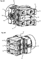
- the blocks 4a, 4b are arranged adjacent, perpendicular to the assembly direction (as on the figures 6A and 6B ). They cooperate with the contact carrier plate 32 by suitable fixing means, detailed below.
- a control and / or signaling device 1 can include up to three adjacent blocks 4a, 4b. When a 4b signaling block is used ( figure 2B ), it is placed in the middle in order to accommodate its luminous member 41b in the opening 30 of the base 3.
- the device for fixing the control and / or signaling member 1 has two fixing points, called first fixing point and second fixing point.
- the two fixing points are opposite with respect to the opening 30 of the base 3, the first fixing point being located in the front front zone and the second fixing point being located in the rear rear zone.
- the two fixing points are defined along two axes A1, A2 which are parallel to each other and to the plane axial median P, and perpendicular to the assembly direction (Y) ( figure 4B ).
- the first axis A1 is located at the front and the second axis A2 is located at the rear.
- the fixing device At the first fixing point, the fixing device has a first threaded hole and at the second fixing point, the fixing device has a second threaded hole.
- the fixing device comprises a first fixing screw 50 to be screwed into the first hole and a second fixing screw 51 to be screwed into the second hole.
- the end of each fixing screw 50, 51 is intended to come to bear against the internal face 21 of the wall 2.
- the amplitude of the screwing makes it possible to adapt to the thickness of the wall 2.
- the heads of the screws fasteners advantageously have a suitable diameter in order to save space.
- each tapped hole is inclined with respect to the main direction (X).
- the first fixing screw 50 is inclined towards the main direction, that is to say from the front to the rear and the second fixing screw, from the head towards the tip, is also tilted towards the main direction, that is to say from the back to the front.
- the screws will point on the internal face, in line or almost with the shoulder 100 of the body 10 of the control and / or signaling member on the external face 20, thus making it possible to avoid the deformation of the wall 2, in particular when the latter is particularly thin.
- the contact carrier plate 32 comprises a first part 320 having a planar assembly face perpendicular to the main direction (X), through which the opening 30 of the base is made and a second curved or folded part 321 which extends along a plane perpendicular to the assembly face, and therefore parallel to the main direction and to the two axes A1, A2 defined above.
- the curved part 321 is produced in a plane P3 located forward with respect to the second axis A2. It is therefore inserted between the second axis A2 and a parallel plane which is tangent to the edge of the opening 30.
- the contact carrier plate 32 comprises fixing means for the blocks 4a, 4b of electrical contact or electrical signaling. These fixing means are located in the front zone and in the rear zone of the base 3.
- the curved part 321 of the plate 32 comprises several reception windows 322, a reception window 322 for each contact block 4a, 4b or signaling.
- the plate 32 has three reception windows 322.
- the plate 32 in its assembly face, comprises several hooking housings 323 aligned in a direction perpendicular to the main direction (X) and to the assembly direction (Y).
- Each hooked housing consists of two identical parallel cutouts 323a, 323b made in the plate.
- Each cutout has a bearing zone 324 produced in a plane P4 located behind the first axis A1, so as to leave accessible the first fixing screw 50 of the device ( figure 4B ).
- This plane P4 is thus arranged between the first axis A1 and a parallel plane which is tangent to the edge of the opening 30.
- an electrical contact block 4a comprises a casing 40 of prismatic form made of insulating material and a pusher 41a projecting above an assembly face 43 of the casing and movable in translation or rotation and a set of fixed and movable contacts housed in the housing.
- the assembly face 43 is intended to come to bear against the flat assembly face of the first part 320 of the plate 32.
- the actuation of a button of the control member actuates the movable pusher and the movable contacts. of the block.
- the contact block can be either normally open (NO) or normally closed (NC).
- a signaling unit 4b comprises for its part, in a casing of identical shape, a luminous member of the light-emitting diode type projecting above its bearing face and intended to illuminate the member on the side of the external face 20 of the wall 2.
- a contact block and a signaling block have identical fixing means, allowing them to fit on the base 3.
- the unit housing further comprises two large opposite flat side faces and two small opposite side faces , one being at the front and the other at the rear.
- the fixing means of the block 4a on the contact carrier plate 32 comprise, at the rear, a spout 42 made on the housing of the block, in the extension of its assembly face 43 and at the front a member of resilient attachment 44, mounted on a spring 45 and comprising two hooks 440 interconnected by a central core 441 and positioned symmetrically.
- the hooking member 44 is biased by its spring 45 in the assembly direction in a direction which goes from the front to the rear.
- the two hooks 440 project from the assembly face 43.
- the spout 42 has a free end which is oriented in the assembly direction, in a direction going from the front to the rear.
- the two hooks are also oriented in the same direction as the spout 42.
- the two hooks extend on either side of the assembly face 43 so as to be positioned on either side of the head of the first fixing screw 50 during assembly .
- the spout 42 does not protrude from the plane formed by the assembly face, allowing it to come directly into a window 322 for receiving the plate 32.
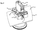
- a block 4 fixed in the center of the base is in line with the two fixing screws 50, 51 ( figure 3 ).
- the central core 441 of the fastening member has a recess 442 making it possible to match the screw head and to leave it accessible when the block is hung in the central position.
- each small side face of the housing 40 of the block comprises an oblique face 46, 47 making it possible to provide an inclined passage for a tool for operating the hooking member 44 located at the front and for the two fixing screws 50 , 51 thus made accessible from the front and rear.
- the beak 42 of a contact or signaling unit 4a, 4b is intended to fit into a reception window 322 of the contact holder plate 32 and after insertion, each hooking member 44 cooperates with the hooked housing 323 provided.
- the hooks 440 may have an inclined portion on their upper part in order to promote the translation of the fastening member.
- each contact block 4a may have a heel 48 which protrudes from said face and which makes it possible to add a second stacked block.
- a signaling block 4b does not have a stub of this type because these blocks are not stackable.
- the second block is fixed in the same way as on the contact carrier plate 32.
- This heel 48 thus plays the role of the reception window 322 present on the contact carrier plate 32.
- Hanging housings 49 are provided at the front of the block and formed from recesses formed on the two large lateral faces of the housing of the block. They are intended to cooperate with the hooking member 44 of the second block which is stacked.
- the figures 5A and 5B thus represent a push-button type control member provided with the fixing device of the invention to which three blocks have been added.
- the central block is a signaling block 4b and the two outer blocks are electrical contact blocks 4a.
- These figures show in particular that the two fixing screws 50, 51 remain accessible after assembly of the blocks, thus allowing easy assembly and disassembly of the member 1 on a wall.
Landscapes
- Engineering & Computer Science (AREA)
- Power Engineering (AREA)
- Casings For Electric Apparatus (AREA)
- Switch Cases, Indication, And Locking (AREA)
- Connection Or Junction Boxes (AREA)
Claims (13)
- Befestigungsvorrichtung für ein Befehls- und/oder Meldeorgan (1), das dazu bestimmt ist, durch eine in einer Wand (2) ausgeführte Öffnung hindurch eingeführt zu werden, und das einen röhrenförmigen Körper (10) beinhaltet, der dazu bestimmt ist, an einer ersten Seite (20) der Wand zur Anlage zu kommen, wobei die Vorrichtung umfasst:- einen Sockel (3), der eine entlang einer Hauptrichtung (X) ausgeführte axiale Öffnung (30) aufweist, die dazu bestimmt ist, den Körper (10) des Befehls- und/oder Meldeorgans aufzunehmen, wobei der Sockel (3) zwischen einem sogenannten vorderen Bereich und einem sogenannten hinteren Bereich entlang einer sogenannten Montagerichtung (Y) ausgerichtet ist, die senkrecht zu der Hauptrichtung (X) verläuft, und einen Träger (31) beinhaltet, an dem der röhrenförmigen Körper befestigt ist, eine Platte (32), die an dem Träger befestigt ist und die Befestigungsmittel zum Befestigen eines oder mehrerer lösbarer Kontakt-oder Meldeblöcke beinhaltet (4a, 4b), wobei die Befestigungsmittel für jeden Kontakt-oder Meldeblock ein Fenster (322) umfassen, das im hinteren Bereich gelegen ist und dazu bestimmt ist, mit einer Einhaknase (42) des Kontakt- oder Meldeblocks zusammenzuwirken, und eine Rastaufnahme (323), die im vorderen Bereich gelegen ist und dazu bestimmt ist, mit einem federnden Einhakorgan (44) des Kontakt-und/oder Meldeblocks (4a, 4b) zusammenzuwirken,dadurch gekennzeichnet dass:- der Sockel (3) eine erste Öffnung beinhaltet, die eine erste Achse (A1) im vorderen Bereich definiert, und eine zweite Öffnung, die eine zweite Achse (A2) im hinteren Bereich definiert, die parallel zu der ersten Achse und senkrecht zu der Montagerichtung (Y) ist,- die Vorrichtung eine erste Befestigungsschraube (50) beinhaltet, die in die erste Öffnung einzuschrauben ist, um an einer ersten Seite der Wand anzuliegen, und eine zweite Befestigungsschraube (51), die in die zweite Öffnung gegen die zweite Seite der Wand einzuschrauben ist, und dass- die Platte (32) einen senkrecht zur Hauptrichtung verlaufenden Teil (320) beinhaltet, durch den hindurch die axiale Öffnung (30) ausgeführt ist, und einen umgebogenen Teil (321), durch den hindurch jedes Fenster (322) zum Aufnehmen einer Einhaknase (42) eines elektrischen Kontakt- oder Meldeblocks ausgeführt ist, wobei der umgebogene Teil (321) in einer Ebene (P3) gebildet ist, die senkrecht zur Montagerichtung (Y) verläuft und zwischen der ersten Achse (A1) und der zweiten Achse (A2) gelegen ist.
- Vorrichtung nach Anspruch 1, dadurch gekennzeichnet, dass jede Rastaufnahme (323) der Platte zwei parallele Ausschnitte (323a, 323b) beinhaltet, die jeweils einen separaten axialen Anlagebereich (324) für einen Haken (440) eines Kontakt- oder Meldeblocks beinhaltet.
- Vorrichtung nach Anspruch 2, dadurch gekennzeichnet, dass bei jeder Rastaufnahme (323) die beiden axialen Anlagebereiche in derselben Ebene ausgeführt sind, die parallel zur ersten Befestigungsebene ist und in Bezug auf diese Ebene dahinter gelegen ist.
- Vorrichtung nach einem der Ansprüche 1 bis 3, dadurch gekennzeichnet, dass die erste Öffnung geneigt ist, so dass die erste Befestigungsschraube, vom Kopf zu ihrer Spitze hin, zur Hauptrichtung (X) hin geneigt ist.
- Vorrichtung nach einem der Ansprüche 1 bis 4, dadurch gekennzeichnet, dass die zweite Öffnung geneigt ist, so dass die zweite Befestigungsschraube, vom Kopf zu ihrer Spitze hin, zur Hauptrichtung (X) hin geneigt ist.
- Befehls- und/oder Meldeorgan (1), das dazu bestimmt ist, durch eine in einer Wand (2) ausgeführte Öffnung hindurch eingeführt zu werden, und das einen röhrenförmigen Körper (10) beinhaltet, der dazu bestimmt ist, an einer ersten Seite (20) der Wand zur Anlage zu kommen, dadurch gekennzeichnet, dass es beinhaltet:- eine Befestigungsvorrichtung wie in einem der Ansprüche 1 bis 5 definiert, wobei die Vorrichtung an ihrem röhrenförmigen Körper (10) verriegelt ist,- mindestens einen Kontaktblock (4a) oder Meldeblock (4b), der ein Gehäuse (40) beinhaltet und Befestigungsmittel, die dazu eingerichtet sind, an der Platte (32) der Befestigungsvorrichtung befestigt zu werden.
- Organ nach Anspruch 6, dadurch gekennzeichnet, dass jeder Kontaktblock (4a) oder Meldeblock (4b) eine Nase (42) beinhaltet, die dazu eingerichtet ist, in ein Aufnahmefenster (322) der Platte (32) eingeführt zu werden, und ein Einhakorgan (44), das dazu eingerichtet ist, mit einer Rastaufnahme (323) der Platte zusammenzuwirken.
- Organ nach Anspruch 7, dadurch gekennzeichnet, dass der Kontaktblock (4a) oder der Meldeblock (4b) eine ebene Montageseite (43) beinhaltet, die dazu bestimmt ist, mit dem quer verlaufenden Teil (320) der Platte zusammenzuwirken, und dass die Nase (42) in der Verlängerung der Montageseite (43) seines Gehäuses (40) ausgeführt ist.
- Organ nach Anspruch 8, dadurch gekennzeichnet, dass jeder Kontaktblock (4a) einen Absatz (48) beinhaltet, der an einer zur Montageseite (43) entgegengesetzten Seite eingerichtet ist und dazu eingerichtet ist, durch Stapeln einen zusätzlichen Kontaktblock aufzunehmen.
- Organ nach einem der Ansprüche 6 bis 9, dadurch gekennzeichnet, dass jedes Einhakorgan zwei Haken (440) beinhaltet und einen zentralen Steg (441), der die beiden Haken verbindet.
- Organ nach Anspruch 10, dadurch gekennzeichnet, dass der zentrale Steg (441) eine Ausnehmung (442) beinhaltet, die dazu ausgebildet ist, einen Zugangsdurchgang zu einer Befestigungsschraube der Befestigungsvorrichtung zu schaffen.
- Organ nach einem der Ansprüche 6 bis 11, dadurch gekennzeichnet, dass die beiden Schrauben dazu eingerichtet sind, zum Lot einer Schulter (100) zu zeigen, die am röhrenförmigen Körper (10) des Organs ausgeführt ist.
- Organ nach einem der Ansprüche 6 bis 12, dadurch gekennzeichnet, dass jeder Kontaktblock (4a) oder Meldeblock (4b) zwei Schrägen (46, 47) beinhaltet, die dazu eingerichtet sind, einen Durchgang für ein Werkzeug zum Betätigen des Einhakorgans (44) und einen Zugang zu den beiden Befestigungsschrauben (50, 51) zu gewährleisten.
Priority Applications (1)
| Application Number | Priority Date | Filing Date | Title |
|---|---|---|---|
| PL19163686T PL3553904T3 (pl) | 2018-04-10 | 2019-03-19 | Urządzenie do mocowania elementu sterującego i/lub sygnalizacyjnego |
Applications Claiming Priority (1)
| Application Number | Priority Date | Filing Date | Title |
|---|---|---|---|
| FR1853091A FR3079973B1 (fr) | 2018-04-10 | 2018-04-10 | Dispositif de fixation d'un organe de commande et/ou de signalisation |
Publications (2)
| Publication Number | Publication Date |
|---|---|
| EP3553904A1 EP3553904A1 (de) | 2019-10-16 |
| EP3553904B1 true EP3553904B1 (de) | 2021-10-20 |
Family
ID=62455735
Family Applications (1)
| Application Number | Title | Priority Date | Filing Date |
|---|---|---|---|
| EP19163686.9A Active EP3553904B1 (de) | 2018-04-10 | 2019-03-19 | Befestigungsvorrichtung eines steuer- und/oder signalisierungsorgans |
Country Status (5)
| Country | Link |
|---|---|
| EP (1) | EP3553904B1 (de) |
| CN (1) | CN110364381B (de) |
| BR (1) | BR102019006029A2 (de) |
| FR (1) | FR3079973B1 (de) |
| PL (1) | PL3553904T3 (de) |
Families Citing this family (1)
| Publication number | Priority date | Publication date | Assignee | Title |
|---|---|---|---|---|
| EP3828910A1 (de) * | 2019-11-26 | 2021-06-02 | Schneider Electric Industries SAS | Steuerungs- und/oder signalisierungskomponente |
Family Cites Families (11)
| Publication number | Priority date | Publication date | Assignee | Title |
|---|---|---|---|---|
| CH554130A (de) * | 1973-04-26 | 1975-01-31 | Olten Ag Elektro Apparatebau | Elektrische baueinheit zum montieren in einer elektrischen anlage. |
| FR2657492B1 (fr) * | 1990-01-19 | 1993-12-10 | Telemecanique | Procede pour fabriquer un dispositif electromecanique precable pour la generation d'ordres et/ou la signalisation d'etats, et dispositif correspondant. |
| FR2735944B1 (fr) * | 1995-06-20 | 1997-07-25 | Schneider Electric Sa | Dispositif de commande ou de signalisation electrique muni d'un bloc amovible |
| FR2735945B1 (fr) * | 1995-06-20 | 1997-07-25 | Schneider Electric Sa | Dispositif de commande ou de signalisation electrique muni d'un bloc amovible |
| FR2735943B1 (fr) * | 1995-06-20 | 1997-08-29 | Schneider Electric Sa | Dispositif de commande ou de signalisation electrique muni d'un bloc amovible |
| FR2765737B1 (fr) * | 1997-07-02 | 1999-09-10 | Schneider Electric Sa | Dispositif de commande ou de signalisation electrique |
| JP4179743B2 (ja) * | 1999-11-10 | 2008-11-12 | Idec株式会社 | 電気部品及びこれを備えた非常停止システム |
| CN102243929A (zh) * | 2010-05-14 | 2011-11-16 | 上海友邦电气(集团)股份有限公司 | 一种按钮开关 |
| JP2011249097A (ja) * | 2010-05-26 | 2011-12-08 | Sumitomo Wiring Syst Ltd | 操作装置 |
| FR2971642B1 (fr) * | 2011-02-16 | 2013-01-18 | Schneider Electric Ind Sas | Dispositif de commande ou de signalisation electrique |
| FR2974681B1 (fr) * | 2011-04-26 | 2013-04-12 | Schneider Electric Ind Sas | Dispositif de commande et/ou de signalisation electrique |
-
2018
- 2018-04-10 FR FR1853091A patent/FR3079973B1/fr not_active Expired - Fee Related
-
2019
- 2019-03-19 EP EP19163686.9A patent/EP3553904B1/de active Active
- 2019-03-19 PL PL19163686T patent/PL3553904T3/pl unknown
- 2019-03-27 BR BR102019006029-8A patent/BR102019006029A2/pt not_active Application Discontinuation
- 2019-04-09 CN CN201910279465.8A patent/CN110364381B/zh active Active
Also Published As
| Publication number | Publication date |
|---|---|
| CN110364381A (zh) | 2019-10-22 |
| PL3553904T3 (pl) | 2022-02-21 |
| CN110364381B (zh) | 2024-04-05 |
| BR102019006029A2 (pt) | 2019-10-29 |
| EP3553904A1 (de) | 2019-10-16 |
| FR3079973B1 (fr) | 2020-03-06 |
| FR3079973A1 (fr) | 2019-10-11 |
Similar Documents
| Publication | Publication Date | Title |
|---|---|---|
| EP3231042B1 (de) | Stromsteckdosenvorrichtung mit mindestens einem verriegelungs- und entriegelungselement | |
| EP2952975B1 (de) | Vorrichtung zum Zusammenbau eines Gehäuserings im Gehäusemittelteil einer Armbanduhr | |
| EP2456024B1 (de) | Stromsteckdose mit Verschlussvorrichtung | |
| EP3360013B1 (de) | Armbanduhr mit abnehmbaren hörner | |
| EP3483997A1 (de) | Elektrisches gerät | |
| EP3553904B1 (de) | Befestigungsvorrichtung eines steuer- und/oder signalisierungsorgans | |
| EP3738491B1 (de) | Ausgabegerät für verbrauchsgüter vom typ flüssige seife, hydroalkoholische lösung | |
| FR2986690A1 (fr) | Dispositif d'acces aux graines pour mangeoire a oiseaux | |
| EP3072194A1 (de) | Schaltanlagenhalterung mit einem verbindungsinstrument zur befestigung davon an einer wanddose, zugehöriges verbindungsinstrument, verbindungsanordnung und elektrische schaltanlage | |
| FR3068171B1 (fr) | Dispositif de fixation pour organe de commande et/ou de signalisation electrique | |
| WO2008059122A1 (fr) | Support d'appareillage electrique | |
| EP1744426B1 (de) | Elektrischer Kasten bestehend aus zwei Elemente die mit einer Zahnstange zusammen befestigt sind | |
| FR2928786A1 (fr) | Distributeur de faisceaux electriques avec coupelle de protection | |
| EP4243219B1 (de) | Standardsteckdose mit sicherheitsverstärkten seitenerdkontakten | |
| EP3297099B1 (de) | Verriegelung zur verrastung einer steckdose in einem elektrischen und/oder telecommunikationsnetz | |
| EP2824785B1 (de) | Gelenkeinheit eines Gehäuses für Elektrogerät, und Bodendose, die eine solche Einheit umfasst | |
| FR2549168A1 (fr) | Systeme d'assemblage d'elements constitutifs identiques ou similaires de boitiers d'appareillage et elements constitutifs dotes d'un tel systeme | |
| EP0555601B1 (de) | Tragvorrichtung für einen Fernsehapparat | |
| FR2974681A1 (fr) | Dispositif de commande et/ou de signalisation electrique | |
| WO2014060666A1 (fr) | Dispositif de bridage d'un verrou pour une porte d'un véhicule automobile et véhicule automobile comprenant un tel dispositif de bridage | |
| EP1475268A1 (de) | Anordnung zur Positionierung und Befestigung eines Ausstatungsteils in einem Kraftfahrzeug | |
| EP1122833B1 (de) | Vorrichtung für den Zusammenbau eines Verbindungsgehäuses und eines Abdeckungsteiles zum Halten und zum Schutz der am Verbinder angeschlossenen Leiter | |
| EP3163698B1 (de) | Unterstützung elektrischen geräts | |
| EP4279687A1 (de) | Flachschlüsselgarnitur und anordnung mit einem flachschlüssel und einer solchen dichtung | |
| FR3008559A1 (fr) | Accessoire de verrouillage pour couvercle de boitier electrique, boite electrique et ensemble de verrouillage integrant un tel accessoire |
Legal Events
| Date | Code | Title | Description |
|---|---|---|---|
| PUAI | Public reference made under article 153(3) epc to a published international application that has entered the european phase |
Free format text: ORIGINAL CODE: 0009012 |
|
| STAA | Information on the status of an ep patent application or granted ep patent |
Free format text: STATUS: THE APPLICATION HAS BEEN PUBLISHED |
|
| AK | Designated contracting states |
Kind code of ref document: A1 Designated state(s): AL AT BE BG CH CY CZ DE DK EE ES FI FR GB GR HR HU IE IS IT LI LT LU LV MC MK MT NL NO PL PT RO RS SE SI SK SM TR |
|
| AX | Request for extension of the european patent |
Extension state: BA ME |
|
| STAA | Information on the status of an ep patent application or granted ep patent |
Free format text: STATUS: REQUEST FOR EXAMINATION WAS MADE |
|
| 17P | Request for examination filed |
Effective date: 20200414 |
|
| RBV | Designated contracting states (corrected) |
Designated state(s): AL AT BE BG CH CY CZ DE DK EE ES FI FR GB GR HR HU IE IS IT LI LT LU LV MC MK MT NL NO PL PT RO RS SE SI SK SM TR |
|
| GRAP | Despatch of communication of intention to grant a patent |
Free format text: ORIGINAL CODE: EPIDOSNIGR1 |
|
| STAA | Information on the status of an ep patent application or granted ep patent |
Free format text: STATUS: GRANT OF PATENT IS INTENDED |
|
| RIC1 | Information provided on ipc code assigned before grant |
Ipc: H01H 19/02 20060101ALN20210624BHEP Ipc: H02B 1/044 20060101AFI20210624BHEP |
|
| INTG | Intention to grant announced |
Effective date: 20210713 |
|
| GRAS | Grant fee paid |
Free format text: ORIGINAL CODE: EPIDOSNIGR3 |
|
| GRAA | (expected) grant |
Free format text: ORIGINAL CODE: 0009210 |
|
| STAA | Information on the status of an ep patent application or granted ep patent |
Free format text: STATUS: THE PATENT HAS BEEN GRANTED |
|
| AK | Designated contracting states |
Kind code of ref document: B1 Designated state(s): AL AT BE BG CH CY CZ DE DK EE ES FI FR GB GR HR HU IE IS IT LI LT LU LV MC MK MT NL NO PL PT RO RS SE SI SK SM TR |
|
| REG | Reference to a national code |
Ref country code: GB Ref legal event code: FG4D Free format text: NOT ENGLISH |
|
| REG | Reference to a national code |
Ref country code: CH Ref legal event code: EP |
|
| REG | Reference to a national code |
Ref country code: IE Ref legal event code: FG4D Free format text: LANGUAGE OF EP DOCUMENT: FRENCH |
|
| REG | Reference to a national code |
Ref country code: DE Ref legal event code: R096 Ref document number: 602019008422 Country of ref document: DE |
|
| REG | Reference to a national code |
Ref country code: AT Ref legal event code: REF Ref document number: 1440705 Country of ref document: AT Kind code of ref document: T Effective date: 20211115 |
|
| REG | Reference to a national code |
Ref country code: LT Ref legal event code: MG9D |
|
| REG | Reference to a national code |
Ref country code: NL Ref legal event code: MP Effective date: 20211020 |
|
| REG | Reference to a national code |
Ref country code: AT Ref legal event code: MK05 Ref document number: 1440705 Country of ref document: AT Kind code of ref document: T Effective date: 20211020 |
|
| PG25 | Lapsed in a contracting state [announced via postgrant information from national office to epo] |
Ref country code: RS Free format text: LAPSE BECAUSE OF FAILURE TO SUBMIT A TRANSLATION OF THE DESCRIPTION OR TO PAY THE FEE WITHIN THE PRESCRIBED TIME-LIMIT Effective date: 20211020 Ref country code: LT Free format text: LAPSE BECAUSE OF FAILURE TO SUBMIT A TRANSLATION OF THE DESCRIPTION OR TO PAY THE FEE WITHIN THE PRESCRIBED TIME-LIMIT Effective date: 20211020 Ref country code: FI Free format text: LAPSE BECAUSE OF FAILURE TO SUBMIT A TRANSLATION OF THE DESCRIPTION OR TO PAY THE FEE WITHIN THE PRESCRIBED TIME-LIMIT Effective date: 20211020 Ref country code: BG Free format text: LAPSE BECAUSE OF FAILURE TO SUBMIT A TRANSLATION OF THE DESCRIPTION OR TO PAY THE FEE WITHIN THE PRESCRIBED TIME-LIMIT Effective date: 20220120 Ref country code: AT Free format text: LAPSE BECAUSE OF FAILURE TO SUBMIT A TRANSLATION OF THE DESCRIPTION OR TO PAY THE FEE WITHIN THE PRESCRIBED TIME-LIMIT Effective date: 20211020 |
|
| PG25 | Lapsed in a contracting state [announced via postgrant information from national office to epo] |
Ref country code: IS Free format text: LAPSE BECAUSE OF FAILURE TO SUBMIT A TRANSLATION OF THE DESCRIPTION OR TO PAY THE FEE WITHIN THE PRESCRIBED TIME-LIMIT Effective date: 20220220 Ref country code: SE Free format text: LAPSE BECAUSE OF FAILURE TO SUBMIT A TRANSLATION OF THE DESCRIPTION OR TO PAY THE FEE WITHIN THE PRESCRIBED TIME-LIMIT Effective date: 20211020 Ref country code: PT Free format text: LAPSE BECAUSE OF FAILURE TO SUBMIT A TRANSLATION OF THE DESCRIPTION OR TO PAY THE FEE WITHIN THE PRESCRIBED TIME-LIMIT Effective date: 20220221 Ref country code: NO Free format text: LAPSE BECAUSE OF FAILURE TO SUBMIT A TRANSLATION OF THE DESCRIPTION OR TO PAY THE FEE WITHIN THE PRESCRIBED TIME-LIMIT Effective date: 20220120 Ref country code: NL Free format text: LAPSE BECAUSE OF FAILURE TO SUBMIT A TRANSLATION OF THE DESCRIPTION OR TO PAY THE FEE WITHIN THE PRESCRIBED TIME-LIMIT Effective date: 20211020 Ref country code: LV Free format text: LAPSE BECAUSE OF FAILURE TO SUBMIT A TRANSLATION OF THE DESCRIPTION OR TO PAY THE FEE WITHIN THE PRESCRIBED TIME-LIMIT Effective date: 20211020 Ref country code: HR Free format text: LAPSE BECAUSE OF FAILURE TO SUBMIT A TRANSLATION OF THE DESCRIPTION OR TO PAY THE FEE WITHIN THE PRESCRIBED TIME-LIMIT Effective date: 20211020 Ref country code: GR Free format text: LAPSE BECAUSE OF FAILURE TO SUBMIT A TRANSLATION OF THE DESCRIPTION OR TO PAY THE FEE WITHIN THE PRESCRIBED TIME-LIMIT Effective date: 20220121 Ref country code: ES Free format text: LAPSE BECAUSE OF FAILURE TO SUBMIT A TRANSLATION OF THE DESCRIPTION OR TO PAY THE FEE WITHIN THE PRESCRIBED TIME-LIMIT Effective date: 20211020 |
|
| REG | Reference to a national code |
Ref country code: DE Ref legal event code: R097 Ref document number: 602019008422 Country of ref document: DE |
|
| PG25 | Lapsed in a contracting state [announced via postgrant information from national office to epo] |
Ref country code: SM Free format text: LAPSE BECAUSE OF FAILURE TO SUBMIT A TRANSLATION OF THE DESCRIPTION OR TO PAY THE FEE WITHIN THE PRESCRIBED TIME-LIMIT Effective date: 20211020 Ref country code: SK Free format text: LAPSE BECAUSE OF FAILURE TO SUBMIT A TRANSLATION OF THE DESCRIPTION OR TO PAY THE FEE WITHIN THE PRESCRIBED TIME-LIMIT Effective date: 20211020 Ref country code: RO Free format text: LAPSE BECAUSE OF FAILURE TO SUBMIT A TRANSLATION OF THE DESCRIPTION OR TO PAY THE FEE WITHIN THE PRESCRIBED TIME-LIMIT Effective date: 20211020 Ref country code: EE Free format text: LAPSE BECAUSE OF FAILURE TO SUBMIT A TRANSLATION OF THE DESCRIPTION OR TO PAY THE FEE WITHIN THE PRESCRIBED TIME-LIMIT Effective date: 20211020 Ref country code: DK Free format text: LAPSE BECAUSE OF FAILURE TO SUBMIT A TRANSLATION OF THE DESCRIPTION OR TO PAY THE FEE WITHIN THE PRESCRIBED TIME-LIMIT Effective date: 20211020 Ref country code: CZ Free format text: LAPSE BECAUSE OF FAILURE TO SUBMIT A TRANSLATION OF THE DESCRIPTION OR TO PAY THE FEE WITHIN THE PRESCRIBED TIME-LIMIT Effective date: 20211020 |
|
| PLBE | No opposition filed within time limit |
Free format text: ORIGINAL CODE: 0009261 |
|
| STAA | Information on the status of an ep patent application or granted ep patent |
Free format text: STATUS: NO OPPOSITION FILED WITHIN TIME LIMIT |
|
| 26N | No opposition filed |
Effective date: 20220721 |
|
| PG25 | Lapsed in a contracting state [announced via postgrant information from national office to epo] |
Ref country code: MC Free format text: LAPSE BECAUSE OF FAILURE TO SUBMIT A TRANSLATION OF THE DESCRIPTION OR TO PAY THE FEE WITHIN THE PRESCRIBED TIME-LIMIT Effective date: 20211020 Ref country code: AL Free format text: LAPSE BECAUSE OF FAILURE TO SUBMIT A TRANSLATION OF THE DESCRIPTION OR TO PAY THE FEE WITHIN THE PRESCRIBED TIME-LIMIT Effective date: 20211020 |
|
| REG | Reference to a national code |
Ref country code: CH Ref legal event code: PL |
|
| PG25 | Lapsed in a contracting state [announced via postgrant information from national office to epo] |
Ref country code: SI Free format text: LAPSE BECAUSE OF FAILURE TO SUBMIT A TRANSLATION OF THE DESCRIPTION OR TO PAY THE FEE WITHIN THE PRESCRIBED TIME-LIMIT Effective date: 20211020 |
|
| REG | Reference to a national code |
Ref country code: BE Ref legal event code: MM Effective date: 20220331 |
|
| PG25 | Lapsed in a contracting state [announced via postgrant information from national office to epo] |
Ref country code: LU Free format text: LAPSE BECAUSE OF NON-PAYMENT OF DUE FEES Effective date: 20220319 Ref country code: LI Free format text: LAPSE BECAUSE OF NON-PAYMENT OF DUE FEES Effective date: 20220331 Ref country code: IE Free format text: LAPSE BECAUSE OF NON-PAYMENT OF DUE FEES Effective date: 20220319 Ref country code: CH Free format text: LAPSE BECAUSE OF NON-PAYMENT OF DUE FEES Effective date: 20220331 |
|
| PG25 | Lapsed in a contracting state [announced via postgrant information from national office to epo] |
Ref country code: BE Free format text: LAPSE BECAUSE OF NON-PAYMENT OF DUE FEES Effective date: 20220331 |
|
| GBPC | Gb: european patent ceased through non-payment of renewal fee |
Effective date: 20230319 |
|
| PG25 | Lapsed in a contracting state [announced via postgrant information from national office to epo] |
Ref country code: GB Free format text: LAPSE BECAUSE OF NON-PAYMENT OF DUE FEES Effective date: 20230319 |
|
| PG25 | Lapsed in a contracting state [announced via postgrant information from national office to epo] |
Ref country code: GB Free format text: LAPSE BECAUSE OF NON-PAYMENT OF DUE FEES Effective date: 20230319 |
|
| PG25 | Lapsed in a contracting state [announced via postgrant information from national office to epo] |
Ref country code: MK Free format text: LAPSE BECAUSE OF FAILURE TO SUBMIT A TRANSLATION OF THE DESCRIPTION OR TO PAY THE FEE WITHIN THE PRESCRIBED TIME-LIMIT Effective date: 20211020 Ref country code: CY Free format text: LAPSE BECAUSE OF FAILURE TO SUBMIT A TRANSLATION OF THE DESCRIPTION OR TO PAY THE FEE WITHIN THE PRESCRIBED TIME-LIMIT Effective date: 20211020 |
|
| PG25 | Lapsed in a contracting state [announced via postgrant information from national office to epo] |
Ref country code: HU Free format text: LAPSE BECAUSE OF FAILURE TO SUBMIT A TRANSLATION OF THE DESCRIPTION OR TO PAY THE FEE WITHIN THE PRESCRIBED TIME-LIMIT; INVALID AB INITIO Effective date: 20190319 |
|
| PG25 | Lapsed in a contracting state [announced via postgrant information from national office to epo] |
Ref country code: MT Free format text: LAPSE BECAUSE OF FAILURE TO SUBMIT A TRANSLATION OF THE DESCRIPTION OR TO PAY THE FEE WITHIN THE PRESCRIBED TIME-LIMIT Effective date: 20211020 |
|
| PGFP | Annual fee paid to national office [announced via postgrant information from national office to epo] |
Ref country code: PL Payment date: 20250307 Year of fee payment: 7 |
|
| PGFP | Annual fee paid to national office [announced via postgrant information from national office to epo] |
Ref country code: TR Payment date: 20250318 Year of fee payment: 7 |
|
| PGFP | Annual fee paid to national office [announced via postgrant information from national office to epo] |
Ref country code: DE Payment date: 20260326 Year of fee payment: 8 |
|
| PGFP | Annual fee paid to national office [announced via postgrant information from national office to epo] |
Ref country code: IT Payment date: 20260320 Year of fee payment: 8 |
|
| PGFP | Annual fee paid to national office [announced via postgrant information from national office to epo] |
Ref country code: FR Payment date: 20260323 Year of fee payment: 8 |