EP3553884A1 - Housing manufacturing method and mobile terminal - Google Patents
Housing manufacturing method and mobile terminal Download PDFInfo
- Publication number
- EP3553884A1 EP3553884A1 EP18741811.6A EP18741811A EP3553884A1 EP 3553884 A1 EP3553884 A1 EP 3553884A1 EP 18741811 A EP18741811 A EP 18741811A EP 3553884 A1 EP3553884 A1 EP 3553884A1
- Authority
- EP
- European Patent Office
- Prior art keywords
- housing
- manufacturing
- slots
- milling
- slot
- Prior art date
- Legal status (The legal status is an assumption and is not a legal conclusion. Google has not performed a legal analysis and makes no representation as to the accuracy of the status listed.)
- Granted
Links
Images
Classifications
-
- B—PERFORMING OPERATIONS; TRANSPORTING
- B29—WORKING OF PLASTICS; WORKING OF SUBSTANCES IN A PLASTIC STATE IN GENERAL
- B29C—SHAPING OR JOINING OF PLASTICS; SHAPING OF MATERIAL IN A PLASTIC STATE, NOT OTHERWISE PROVIDED FOR; AFTER-TREATMENT OF THE SHAPED PRODUCTS, e.g. REPAIRING
- B29C45/00—Injection moulding, i.e. forcing the required volume of moulding material through a nozzle into a closed mould; Apparatus therefor
- B29C45/0053—Injection moulding, i.e. forcing the required volume of moulding material through a nozzle into a closed mould; Apparatus therefor combined with a final operation, e.g. shaping
-
- B—PERFORMING OPERATIONS; TRANSPORTING
- B29—WORKING OF PLASTICS; WORKING OF SUBSTANCES IN A PLASTIC STATE IN GENERAL
- B29C—SHAPING OR JOINING OF PLASTICS; SHAPING OF MATERIAL IN A PLASTIC STATE, NOT OTHERWISE PROVIDED FOR; AFTER-TREATMENT OF THE SHAPED PRODUCTS, e.g. REPAIRING
- B29C45/00—Injection moulding, i.e. forcing the required volume of moulding material through a nozzle into a closed mould; Apparatus therefor
- B29C45/14—Injection moulding, i.e. forcing the required volume of moulding material through a nozzle into a closed mould; Apparatus therefor incorporating preformed parts or layers, e.g. injection moulding around inserts or for coating articles
- B29C45/1418—Injection moulding, i.e. forcing the required volume of moulding material through a nozzle into a closed mould; Apparatus therefor incorporating preformed parts or layers, e.g. injection moulding around inserts or for coating articles the inserts being deformed or preformed, e.g. by the injection pressure
-
- B—PERFORMING OPERATIONS; TRANSPORTING
- B29—WORKING OF PLASTICS; WORKING OF SUBSTANCES IN A PLASTIC STATE IN GENERAL
- B29C—SHAPING OR JOINING OF PLASTICS; SHAPING OF MATERIAL IN A PLASTIC STATE, NOT OTHERWISE PROVIDED FOR; AFTER-TREATMENT OF THE SHAPED PRODUCTS, e.g. REPAIRING
- B29C45/00—Injection moulding, i.e. forcing the required volume of moulding material through a nozzle into a closed mould; Apparatus therefor
- B29C45/14—Injection moulding, i.e. forcing the required volume of moulding material through a nozzle into a closed mould; Apparatus therefor incorporating preformed parts or layers, e.g. injection moulding around inserts or for coating articles
- B29C45/14311—Injection moulding, i.e. forcing the required volume of moulding material through a nozzle into a closed mould; Apparatus therefor incorporating preformed parts or layers, e.g. injection moulding around inserts or for coating articles using means for bonding the coating to the articles
-
- B—PERFORMING OPERATIONS; TRANSPORTING
- B29—WORKING OF PLASTICS; WORKING OF SUBSTANCES IN A PLASTIC STATE IN GENERAL
- B29C—SHAPING OR JOINING OF PLASTICS; SHAPING OF MATERIAL IN A PLASTIC STATE, NOT OTHERWISE PROVIDED FOR; AFTER-TREATMENT OF THE SHAPED PRODUCTS, e.g. REPAIRING
- B29C45/00—Injection moulding, i.e. forcing the required volume of moulding material through a nozzle into a closed mould; Apparatus therefor
- B29C45/14—Injection moulding, i.e. forcing the required volume of moulding material through a nozzle into a closed mould; Apparatus therefor incorporating preformed parts or layers, e.g. injection moulding around inserts or for coating articles
- B29C45/14467—Joining articles or parts of a single article
-
- H—ELECTRICITY
- H01—ELECTRIC ELEMENTS
- H01Q—ANTENNAS, i.e. RADIO AERIALS
- H01Q1/00—Details of, or arrangements associated with, antennas
- H01Q1/12—Supports; Mounting means
- H01Q1/22—Supports; Mounting means by structural association with other equipment or articles
- H01Q1/24—Supports; Mounting means by structural association with other equipment or articles with receiving set
- H01Q1/241—Supports; Mounting means by structural association with other equipment or articles with receiving set used in mobile communications, e.g. GSM
- H01Q1/242—Supports; Mounting means by structural association with other equipment or articles with receiving set used in mobile communications, e.g. GSM specially adapted for hand-held use
- H01Q1/243—Supports; Mounting means by structural association with other equipment or articles with receiving set used in mobile communications, e.g. GSM specially adapted for hand-held use with built-in antennas
- H01Q1/244—Supports; Mounting means by structural association with other equipment or articles with receiving set used in mobile communications, e.g. GSM specially adapted for hand-held use with built-in antennas extendable from a housing along a given path
-
- H—ELECTRICITY
- H01—ELECTRIC ELEMENTS
- H01Q—ANTENNAS, i.e. RADIO AERIALS
- H01Q13/00—Waveguide horns or mouths; Slot antennas; Leaky-waveguide antennas; Equivalent structures causing radiation along the transmission path of a guided wave
- H01Q13/10—Resonant slot antennas
-
- H—ELECTRICITY
- H04—ELECTRIC COMMUNICATION TECHNIQUE
- H04M—TELEPHONIC COMMUNICATION
- H04M1/00—Substation equipment, e.g. for use by subscribers
- H04M1/02—Constructional features of telephone sets
-
- H—ELECTRICITY
- H04—ELECTRIC COMMUNICATION TECHNIQUE
- H04M—TELEPHONIC COMMUNICATION
- H04M1/00—Substation equipment, e.g. for use by subscribers
- H04M1/02—Constructional features of telephone sets
- H04M1/0202—Portable telephone sets, e.g. cordless phones, mobile phones or bar type handsets
-
- B—PERFORMING OPERATIONS; TRANSPORTING
- B29—WORKING OF PLASTICS; WORKING OF SUBSTANCES IN A PLASTIC STATE IN GENERAL
- B29C—SHAPING OR JOINING OF PLASTICS; SHAPING OF MATERIAL IN A PLASTIC STATE, NOT OTHERWISE PROVIDED FOR; AFTER-TREATMENT OF THE SHAPED PRODUCTS, e.g. REPAIRING
- B29C45/00—Injection moulding, i.e. forcing the required volume of moulding material through a nozzle into a closed mould; Apparatus therefor
- B29C45/14—Injection moulding, i.e. forcing the required volume of moulding material through a nozzle into a closed mould; Apparatus therefor incorporating preformed parts or layers, e.g. injection moulding around inserts or for coating articles
- B29C2045/1486—Details, accessories and auxiliary operations
- B29C2045/14868—Pretreatment of the insert, e.g. etching, cleaning
-
- B—PERFORMING OPERATIONS; TRANSPORTING
- B29—WORKING OF PLASTICS; WORKING OF SUBSTANCES IN A PLASTIC STATE IN GENERAL
- B29C—SHAPING OR JOINING OF PLASTICS; SHAPING OF MATERIAL IN A PLASTIC STATE, NOT OTHERWISE PROVIDED FOR; AFTER-TREATMENT OF THE SHAPED PRODUCTS, e.g. REPAIRING
- B29C2793/00—Shaping techniques involving a cutting or machining operation
- B29C2793/0036—Slitting
-
- B—PERFORMING OPERATIONS; TRANSPORTING
- B29—WORKING OF PLASTICS; WORKING OF SUBSTANCES IN A PLASTIC STATE IN GENERAL
- B29C—SHAPING OR JOINING OF PLASTICS; SHAPING OF MATERIAL IN A PLASTIC STATE, NOT OTHERWISE PROVIDED FOR; AFTER-TREATMENT OF THE SHAPED PRODUCTS, e.g. REPAIRING
- B29C2793/00—Shaping techniques involving a cutting or machining operation
- B29C2793/0054—Shaping techniques involving a cutting or machining operation partially cutting through the material
-
- B—PERFORMING OPERATIONS; TRANSPORTING
- B29—WORKING OF PLASTICS; WORKING OF SUBSTANCES IN A PLASTIC STATE IN GENERAL
- B29C—SHAPING OR JOINING OF PLASTICS; SHAPING OF MATERIAL IN A PLASTIC STATE, NOT OTHERWISE PROVIDED FOR; AFTER-TREATMENT OF THE SHAPED PRODUCTS, e.g. REPAIRING
- B29C67/00—Shaping techniques not covered by groups B29C39/00 - B29C65/00, B29C70/00 or B29C73/00
- B29C67/004—Closing perforations or small holes, e.g. using additional moulding material
-
- B—PERFORMING OPERATIONS; TRANSPORTING
- B29—WORKING OF PLASTICS; WORKING OF SUBSTANCES IN A PLASTIC STATE IN GENERAL
- B29K—INDEXING SCHEME ASSOCIATED WITH SUBCLASSES B29B, B29C OR B29D, RELATING TO MOULDING MATERIALS OR TO MATERIALS FOR MOULDS, REINFORCEMENTS, FILLERS OR PREFORMED PARTS, e.g. INSERTS
- B29K2705/00—Use of metals, their alloys or their compounds, for preformed parts, e.g. for inserts
- B29K2705/02—Aluminium
Definitions
- the present disclosure relates to the technical field of manufacturing processes of housings of mobile terminals, and in particular to a method for manufacturing a housing and a mobile terminal.
- a plurality of slots for antennas are generally defined in the metal housings to meet the requirements of radio frequencies of antennas.
- the slots for the antennas are filled with glue to connect metal portions on both sides of each slot of the antennas, in order to form complete housings of the mobile phones.
- the housings may be easily deformed by forces during the milling process and subsequent processes, which results in a low yield of the housings and a high production cost.
- the present disclosure provides a method for manufacturing a housing and a mobile terminal, which solves the problems of low yield of the housing and high production cost in the related art.
- the method may include the following.
- a mobile terminal may be further provided in the present disclosure.
- the mobile terminal may include any housing manufatured by the method for manufacturing the housing described above, a display assembly disposed on the housing, and a circuit disposed in the housing.
- the beneficial effects of the present disclosure are as follows: the plurality of slots are defined by cutting through the housing by means of milling, the plastic layer formed on the first surface supports the housing, such that the metal portion between adjacent slots keeps undeformed during the milling, thereby increasing the yield of the housing, and reducing production cost.
- a method for manufacturing a housing may be provided.
- the method may be used for manufacturing the housing for the mobile terminal.
- the housing may be configured as an external shell of the mobile terminal.
- the mobile terminal may further include a display assembly disposed on the housing and a circuit disposed in the housing.
- the mobile terminal may be implemented as a mobile phone, a tablet computer, a laptop, and the like.
- the housing may be mounted on a back of the mobile terminal.
- the housing may be configured to protect components (such as a main board, a battery, and the like) at an inner side of the mobile terminal.
- the housing may be further configured to beautify the structure of the mobile terminal, and attract eyes of consumers.
- the housing may be a metal housing.
- the metal housing may have a metallic texture and may be extremely attractive.
- the metal housing may be made of aluminum alloy material.
- the aluminum alloy material is light in weight, difficult to oxidize, and easy to process.
- Antenna signals inside the mobile terminal may be easily shielded by the metal housing.
- the metal housing needs to be cut through by milling to define a slot for an antenna in the housing, in order to allow communication signals to pass therethrough.
- the housing 10 may include a plurality of slots for an antenna. In some embodiments, three slots for the antenna may be provided, and in other embodiments, other numbers of slots may also be provided.
- the slots may include a first slot 101, a second slot 102, and a third slot 103.
- the first slot 101, the second slot 102, and the third slot 103 may be arranged in sequence and parallel to each other.
- Each of the first slot 101, the second slot 102, and the third slot 103 may have a narrow width, and a width of a metal portion between two adjacent slots is also narrow.
- each slot may have a width of 0.3mm-0.5mm, and the metal part may generally have a width of 0.5mm ⁇ 1mm.
- the metal portion may be elongated. More specifically, the metal portion between the first slot 101 and the second slot 102 may be a first metal strip 121, and the metal portion between the second slot 102 and the third slot 103 may be a second metal strip 122.
- the widths of the first metal strip 121 and the second metal strip 122 are less than 1 mm, respectively, while the first metal strip 121 and the second metal strip 122 covers the entire housing 10 along the lengthwise direction of the first metal strip 121 and the second metal strip 122, and thus the metal portion may have a low strength.
- the process of defining the slot in the housing 10 by means of milling may further include the following.
- FIG. 2 is a flow chart of a method for manufacturing the housing 10 according to some embodiments of the present disclosure. As shown in the figure, the method for manufacturing the housing 10 may include the following blocks.
- a first surface 11 of the housing may be roughened.
- the housing 10 may include the first surface 11 and a second surface 12 opposite to each other.
- the first surface 11 is a surface of the finished housing that faces towards an inner cavity of the mobile terminal after the finished housing has been manufactured in subsequent processes (that is, an inner surface).
- the second surface 12 is a surface of the finished housing that faces away from the inner cavity of the mobile terminal after the finished housing has been manufactured in subsequent processes (that is, an outer surface).
- a T treatment may be performed to define a nano-sized pit on the first surface 11 of the housing 10 to roughen the first surface 11, such that the roughness of the first surface 11 may be increased, and it is convenient for subsequent injection molding performed on the first surface 11, and thus a firmly bonded plastic layer 20 may be formed on the first surface 11.
- the first surface 11 may be roughened by means of the T treatment or a mechanical process. In some embodiments, the first surface 11 may be roughened by the T treatment.
- the T treatment is a processing technique that uses T solution to corrode the metal surface to form the nano-sized pit.
- the T treatment may be applied to a pretreatment of the metal surface, and belong to nano molding technology.
- the T treatment may include the following.
- the T treatment may be repeated a plurality of times to form the nano-sized pit, based on the material of the housing 10 and the corrosion resistance.
- the housing 10 having a plurality of nano-sized pits defined on the first surface 11 may be obtained.
- the housing 10 may be placed in a mold and an injection molding may be performed.
- the housing 10 may be clamped in the mold using a clamp, and the injection molding may be performed.
- the plastic material for injection molding may be resin.
- the plastic material may enter the nano-sized pits on the first surface 11 to form the plastic layer 20 on the first surface 11.
- the plastic layer 20 may be closely bonded to the housing 10. More specifically, when the plastic material is integrally injected on the metal, an ester-amine chemical exothermic reaction may occur between the lipoamino acid and the plastic material. In this way, it is possible to delay the curing of the plastic material and facilitate the exchange of positions of the lipoamino acid and the plastic material, thereby ensuring that the plastic material may successfully enter into the nano-sized pits.
- the housing 10 may be cut through by means of milling to define a slot for the antenna.
- the housing 10 in the process of defining the slot for the antenna, only the housing 10 may be cut through by milling, and the plastic layer 20 may not be cut through by milling. Thus, the housing 10 may be supported by the plastic layer 20, such that the first metal strip 121 and the second metal strip 122 between the adjacent slots will not be bent or deformed during the milling process.
- the housing 10 may be placed on a machine table of a four-axis computer numerical control (CNC) machine having a rotary function.
- the first surface 11 may be placed on the machine table.
- a milling cutter 30 may be inserted to start milling the housing 10 from the surface of the housing 10 that is away from the plastic layer 20, that is, the second surface 12.
- the milling cutter 30 may finally pass out from the first surface 11, and an over-milled groove 302 may be milled in the plastic layer 20 to ensure that the slot for the antenna may completely cut through the housing 10.
- the over-milled groove 302 may have a depth of 0.1 mm ⁇ 0.3 mm.
- the design of the over-milled slot 302 may ensure that the housing 10 is completely cut through by milling without cutting through the plastic layer 20 disposed on the first surface 11. Thus, the plastic layer 20 may still provide a support to the housing 10. In this way, it is possible to maintain the strength of the metal portion between the adjacent slots, such that the metal portion may not be bent, deformed, or even broken during the milling process, thereby increasing the yield of the housing 10 and reducing the production cost.
- glue 40 needs to be filled in the slot to fill up the slot, in order to maintain the integrity of the housing 10 and provide a protection to the components such as the main board, the battery, and the like inside the mobile terminal by the housing 10.
- the glue 40 may be filled in the slot for the antenna by a four-axis dispenser, and the glue 40 may fill up the slot in a self-leveling manner.
- the process may be simple and easy to operate.
- an adhesion strength between the glue 40 and the metal housing 10 may be low, such that the structural stability requirements of the housing 10 cannot be met.
- the T treatment may needs to be performed on the housing 10, such that nano-sized pits may be defined on an inner wall surface 1010 of the formed slot, the inner wall surface 1010 may be roughened, and the adhesion between the inner wall surface 1010 and the glue 40 may be improved.
- filling the glue 40 may include the following.
- the inner wall surface 1010 of the housing 10 may be roughened.
- the inner wall surface 1010 may be roughened by the T treatment.
- the T treatment is a processing technique that uses T solution to corrode the metal surface to form the nano-sized pits.
- the T treatment may be applied to a pretreatment of the metal surface, and belong to nano molding technology.
- the T treatment may include the following.
- the T treatment may be repeated a plurality of times to form the nano-sized pits, based on the material of the housing 10 and the corrosion resistance.
- the housing 10 having a plurality of nano-sized pits defined on the inner wall surface 1010 may be obtained.
- the glue 40 may be filled into the slot.
- the glue 40 may be filled in the slot for the antenna by a four-axis dispenser, and the glue 40 may fill up the slot in a self-leveling manner.
- the filled glue 40 may be resin.
- the glue 40 may enter the nano-sized pits defined on the inner wall surface 1010, and be closely bonded to the inner wall surface 1010. Further, an ester-amine chemical exothermic reaction may occur between the lipoamino acid and the glue 40. In this way, it is possible to delay the curing of the glue 40, facilitate the exchange of positions of the lipoamino acid and the glue 40, thereby ensuring that the glue 40 may successfully enter into the nano-sized pits.
- the glue 40 may be closely bonded to the inner wall surface 1010 of the slot. That is, the glue 40 may be closely bonded to the metal portions on both sides of the slot.
- the second slot 102 may be closely bonded to the first metal strip 121 and the second metal strip 122.
- the housing 10 may have a high strength, the yield of the housing 10 may be increased, and the production cost may be reduced.
- the housing 10 may be baked to cure the glue 40.
- the housing 10 may be baked at a baking temperature of 120°C for 30 minutes.
- a plurality of nano-sized pits may be defined on the inner wall surface 1010 of the slot for the antenna, thereby increasing the roughness of the inner wall surface 1010, and effectively improving the bonding force between the glue 40 and the inner wall surface 1010.
- the glue 40 may be bonded to the metal portions on both sides of the slot via the inner wall surface 1010. Therefore, it is possible to increase the adhesion between the glue 40 and the metal portions on both sides of the slot.
- the housing 10 may have a high strength, the yield of the housing 10 may be increased, and the production cost may be reduced.
- the housing 10 may be initially made of an aluminum alloy profile. More specifically, before the housing 10 is cut through by milling to form the slot, the method for manufacturing the housing 10 provided in some embodiments of the present disclosure may further include the followings.
- the first surface 11 of the housing 10 may be placed on a fixture, and metal processes, including lathing, milling, grinding, cutting, and the like, may be performed on the second surface 12, such that the thicknesses of each part of the sheet may be changed.
- metal processes including lathing, milling, grinding, cutting, and the like, may be performed on the second surface 12, such that the thicknesses of each part of the sheet may be changed.
- the prototype of the structure of the housing 10 may be formed, and the processing process may be simple and easy to operate, which may facilitate subsequent processing of the slot of the antenna.
- the housing needs to be machined by finish machining to form a finished product of the housing. More specifically, after the glue 40 has been filled in the slot, the method for manufacturing the housing 10 provided in some embodiments of the present disclosure may further include the following.
- the plastic layer 20 disposed on the first surface 11 may be removed during the polishing process, and the appearance of the housing 10 may be beautified by sandblasting and anodization to achieve the decorative effect.
- the plastic layer 20 disposed on the first surface 11 may support the housing 10, and the metal portion between the adjacent slots may not be deformed during the milling process, thereby increasing the yield of the housing 10 and reducing the production cost.
- a mobile terminal may also be provided in some embodiments of the present disclosure.
- the mobile terminal may include the aforementioned housing 10, a display assembly disposed on the housing 10, and a circuit disposed in the housing 10.
- the mobile terminal may refer to a computer device that may be used on the move, and may include but be not limited to a mobile phone, a notebook, a tablet computer, a POS device, an in-vehicle computer, a camera, and the like.
Landscapes
- Engineering & Computer Science (AREA)
- Manufacturing & Machinery (AREA)
- Mechanical Engineering (AREA)
- Computer Networks & Wireless Communication (AREA)
- Signal Processing (AREA)
- Casings For Electric Apparatus (AREA)
- Telephone Set Structure (AREA)
Abstract
Description
- The present disclosure relates to the technical field of manufacturing processes of housings of mobile terminals, and in particular to a method for manufacturing a housing and a mobile terminal.
- With the widely application of mobile phones, people have higher and higher requirements on appearance of housings of the mobile phones. Metal housings are becoming more and more popular with consumers due to the novel appearance. In order to prevent the metal housings from shielding antenna signals, a plurality of slots for antennas are generally defined in the metal housings to meet the requirements of radio frequencies of antennas. Besides, the slots for the antennas are filled with glue to connect metal portions on both sides of each slot of the antennas, in order to form complete housings of the mobile phones.
- In the related art, if the slots are defined in the housings by directly cutting through the housings by means of milling, the housings may be easily deformed by forces during the milling process and subsequent processes, which results in a low yield of the housings and a high production cost.
- The present disclosure provides a method for manufacturing a housing and a mobile terminal, which solves the problems of low yield of the housing and high production cost in the related art.
- To solve the above technical problem, a method for manufacturing a housing is provided in the present disclosure. The method may include the following.
- Roughening a first surface of the housing.
- Placing the housing into a mold and performing an injection molding to form a plastic layer on the first surface and closely bonded to the housing.
- Defining a plurality of slots by cutting through the housing by means of milling without milling a part or all of the plastic layer, wherein the plastic layer is configured to keep a metal portion between adjacent slots defined in the housing undeformed during the milling.
- A mobile terminal may be further provided in the present disclosure. The mobile terminal may include any housing manufatured by the method for manufacturing the housing described above, a display assembly disposed on the housing, and a circuit disposed in the housing.
- The beneficial effects of the present disclosure are as follows: the plurality of slots are defined by cutting through the housing by means of milling, the plastic layer formed on the first surface supports the housing, such that the metal portion between adjacent slots keeps undeformed during the milling, thereby increasing the yield of the housing, and reducing production cost.
- In order to make the technical solution described in the embodiments of the present disclosure or the technical solution in the related art more clear, the drawings used for the description of the embodiments and the related art will be briefly described. Apparently, the drawings described below are only some embodiments of the present disclosure. It should be understood that, one skilled in the art may acquire other obvious modifications based on these drawings without any inventive effort.
-
FIG. 1 illustrates a schematic structural view of a housing according to some embodiments of the present disclosure. -
FIG. 2 illustrates a flow chart of a method for manufacturing the housing according to some embodiments of the present disclosure. -
FIG. 3 illustrates a schematic structural view corresponding to block S103 of the method for manufacturing the housing according to some embodiments of present disclosure. -
FIG. 4 illustrates a schematic structural view of the housing filled with glue by the method for manufacturing the housing according to some embodiments of present disclosure. - The technical solutions of embodiments of the present disclosure will be described clearly and completely with reference to the drawings of the embodiments of the present disclosure. Apparently, the embodiments described here are only some exemplary embodiments, not all the embodiments. Based on the embodiments described in the present disclosure, one skilled in the art may acquire all other embodiments without any creative effort. All these shall be covered within the protection scope of the present disclosure.
- In some embodiments of the present disclosure, a method for manufacturing a housing may be provided. The method may be used for manufacturing the housing for the mobile terminal. The housing may be configured as an external shell of the mobile terminal. The mobile terminal may further include a display assembly disposed on the housing and a circuit disposed in the housing. The mobile terminal may be implemented as a mobile phone, a tablet computer, a laptop, and the like.
- The housing may be mounted on a back of the mobile terminal. On one hand, the housing may be configured to protect components (such as a main board, a battery, and the like) at an inner side of the mobile terminal. On the other hand, the housing may be further configured to beautify the structure of the mobile terminal, and attract eyes of consumers.
- In some embodiments, the housing may be a metal housing. The metal housing may have a metallic texture and may be extremely attractive. In a preferred embodiment, the metal housing may be made of aluminum alloy material. The aluminum alloy material is light in weight, difficult to oxidize, and easy to process.
- Antenna signals inside the mobile terminal may be easily shielded by the metal housing. Thus, the metal housing needs to be cut through by milling to define a slot for an antenna in the housing, in order to allow communication signals to pass therethrough.
- Based on the consideration of communication requirements of the mobile terminal and aesthetic appearance of the housing, in general, it is necessary to design a plurality of slots in the
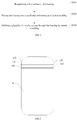
housing 10. The specific structure of the housing may be shown inFIG. 1 . Thehousing 10 may include a plurality of slots for an antenna. In some embodiments, three slots for the antenna may be provided, and in other embodiments, other numbers of slots may also be provided. The slots may include afirst slot 101, asecond slot 102, and athird slot 103. Thefirst slot 101, thesecond slot 102, and thethird slot 103 may be arranged in sequence and parallel to each other. Each of thefirst slot 101, thesecond slot 102, and thethird slot 103 may have a narrow width, and a width of a metal portion between two adjacent slots is also narrow. More specifically, each slot may have a width of 0.3mm-0.5mm, and the metal part may generally have a width of 0.5mm∼1mm. In some embodiments, the metal portion may be elongated. More specifically, the metal portion between thefirst slot 101 and thesecond slot 102 may be afirst metal strip 121, and the metal portion between thesecond slot 102 and thethird slot 103 may be asecond metal strip 122. The widths of thefirst metal strip 121 and thesecond metal strip 122 are less than 1 mm, respectively, while thefirst metal strip 121 and thesecond metal strip 122 covers theentire housing 10 along the lengthwise direction of thefirst metal strip 121 and thesecond metal strip 122, and thus the metal portion may have a low strength. During the process of defining the slot in thehousing 10 by means of milling, thefirst metal strip 121 and thesecond metal strip 122 may be easily bent, deformed, and even broken by forces. Therefore, the process of defining the slot by cutting through thehousing 10 by means of milling may further include the following. -
FIG. 2 is a flow chart of a method for manufacturing thehousing 10 according to some embodiments of the present disclosure. As shown in the figure, the method for manufacturing thehousing 10 may include the following blocks. - At block S101, a
first surface 11 of the housing may be roughened. - More specifically, the
housing 10 may include thefirst surface 11 and asecond surface 12 opposite to each other. Thefirst surface 11 is a surface of the finished housing that faces towards an inner cavity of the mobile terminal after the finished housing has been manufactured in subsequent processes (that is, an inner surface). Thesecond surface 12 is a surface of the finished housing that faces away from the inner cavity of the mobile terminal after the finished housing has been manufactured in subsequent processes (that is, an outer surface). A T treatment may be performed to define a nano-sized pit on thefirst surface 11 of thehousing 10 to roughen thefirst surface 11, such that the roughness of thefirst surface 11 may be increased, and it is convenient for subsequent injection molding performed on thefirst surface 11, and thus a firmly bondedplastic layer 20 may be formed on thefirst surface 11. - The
first surface 11 may be roughened by means of the T treatment or a mechanical process. In some embodiments, thefirst surface 11 may be roughened by the T treatment. The T treatment is a processing technique that uses T solution to corrode the metal surface to form the nano-sized pit. The T treatment may be applied to a pretreatment of the metal surface, and belong to nano molding technology. - More specifically, the T treatment may include the following.
- 1. The
housing 10 may be immersed in alkali solution, such that thefirst surface 11 may be cleaned and grease on thefirst surface 11 may be removed. In a preferred embodiment, the alkali solution may be weak base at a pH of 9 to 10. The requirements of the cleanliness of thefirst surface 11 may be achieved by immersing the housing in the solution for one minute. - 2. The
housing 10 may be immersed in acid solution to neutralize the pH of thefirst surface 11. - 3. The
housing 10 may be immersed in the T solution to form a nano-sized pit on thefirst surface 11. More specifically, the T solution may contain a plurality of chemical agents, and lipoamino acid may be the main component of the T solution. After being immersed in the T solution, thefirst surface 11 may define the pit having a diameter of 20-30 nm, and the pit may be in shape of a coral reef. After the T treatment, the lipoamino acid may remain in the nano-sized pit in preparation for subsequent formation of theplastic layer 20 on thefirst surface 11. - 4. The
housing 10 may be placed in water for washing, and the chemical solution remaining in thehousing 10 may be removed. - 5. The
housing 10 may be dried for subsequent use. - Further, the T treatment may be repeated a plurality of times to form the nano-sized pit, based on the material of the
housing 10 and the corrosion resistance. - In this way, the
housing 10 having a plurality of nano-sized pits defined on thefirst surface 11 may be obtained. - At block S102, the
housing 10 may be placed in a mold and an injection molding may be performed. - More specifically, after being washed by water and further dried, the
housing 10 may be clamped in the mold using a clamp, and the injection molding may be performed. In some embodiments, the plastic material for injection molding may be resin. The plastic material may enter the nano-sized pits on thefirst surface 11 to form theplastic layer 20 on thefirst surface 11. Theplastic layer 20 may be closely bonded to thehousing 10. More specifically, when the plastic material is integrally injected on the metal, an ester-amine chemical exothermic reaction may occur between the lipoamino acid and the plastic material. In this way, it is possible to delay the curing of the plastic material and facilitate the exchange of positions of the lipoamino acid and the plastic material, thereby ensuring that the plastic material may successfully enter into the nano-sized pits. - At block S103, the
housing 10 may be cut through by means of milling to define a slot for the antenna. - In some embodiments, in the process of defining the slot for the antenna, only the
housing 10 may be cut through by milling, and theplastic layer 20 may not be cut through by milling. Thus, thehousing 10 may be supported by theplastic layer 20, such that thefirst metal strip 121 and thesecond metal strip 122 between the adjacent slots will not be bent or deformed during the milling process. - More specifically, combing with
FIG. 3 , thehousing 10 may be placed on a machine table of a four-axis computer numerical control (CNC) machine having a rotary function. Thefirst surface 11 may be placed on the machine table. Amilling cutter 30 may be inserted to start milling thehousing 10 from the surface of thehousing 10 that is away from theplastic layer 20, that is, thesecond surface 12. Themilling cutter 30 may finally pass out from thefirst surface 11, and anover-milled groove 302 may be milled in theplastic layer 20 to ensure that the slot for the antenna may completely cut through thehousing 10. Preferably, theover-milled groove 302 may have a depth of 0.1 mm∼0.3 mm. - The design of the
over-milled slot 302 may ensure that thehousing 10 is completely cut through by milling without cutting through theplastic layer 20 disposed on thefirst surface 11. Thus, theplastic layer 20 may still provide a support to thehousing 10. In this way, it is possible to maintain the strength of the metal portion between the adjacent slots, such that the metal portion may not be bent, deformed, or even broken during the milling process, thereby increasing the yield of thehousing 10 and reducing the production cost. - After the slot for the antenna has been cut through by milling in the
housing 10,glue 40 needs to be filled in the slot to fill up the slot, in order to maintain the integrity of thehousing 10 and provide a protection to the components such as the main board, the battery, and the like inside the mobile terminal by thehousing 10. - In some embodiments, the
glue 40 may be filled in the slot for the antenna by a four-axis dispenser, and theglue 40 may fill up the slot in a self-leveling manner. The process may be simple and easy to operate. - Further, an adhesion strength between the
glue 40 and themetal housing 10 may be low, such that the structural stability requirements of thehousing 10 cannot be met. Thus, the T treatment may needs to be performed on thehousing 10, such that nano-sized pits may be defined on aninner wall surface 1010 of the formed slot, theinner wall surface 1010 may be roughened, and the adhesion between theinner wall surface 1010 and theglue 40 may be improved. - In other embodiments, filling the
glue 40 may include the following. - At block 1, the
inner wall surface 1010 of thehousing 10 may be roughened. - In some embodiments, the
inner wall surface 1010 may be roughened by the T treatment. The T treatment is a processing technique that uses T solution to corrode the metal surface to form the nano-sized pits. The T treatment may be applied to a pretreatment of the metal surface, and belong to nano molding technology. - More specifically, the T treatment may include the following.
- 1. The
housing 10 may be immersed in alkali solution, such that theinner wall surface 1010 may be cleaned and grease on theinner wall surface 1010 may be removed. In a preferred embodiment, the alkali solution may be weak base at a pH of 9 to 10. The requirements of the cleanliness of theinner wall surface 1010 may be achieved by immersing the housing in the solution for one minute. - 2. The
housing 10 may be immersed in acid solution to neutralize the pH of theinner wall surface 1010. - 3. The
housing 10 may be immersed in the T solution to form a nano-sized pit on theinner wall surface 1010. More specifically, the T solution may contain a plurality of chemical agents, and lipoamino acid may be the main component of the T solution. After being immersed in the T solution, theinner wall surface 1010 may define the pit having a diameter of 20-30 nm, and the pit may be in shape of a coral reef. After the T treatment, the lipoamino acid may remain in the nano-sized pit in preparation for subsequent formation of theplastic layer 20 on theinner wall surface 1010. - 4. The
housing 10 may be placed in water for washing, and the chemical solution remaining in thehousing 10 may be removed. - 5. The
housing 10 may be dried for subsequent use. - Further, the T treatment may be repeated a plurality of times to form the nano-sized pits, based on the material of the
housing 10 and the corrosion resistance. - In this way, the
housing 10 having a plurality of nano-sized pits defined on theinner wall surface 1010 may be obtained. - At block 2, the
glue 40 may be filled into the slot. - Combining with
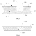
FIG. 4 , more specifically, theglue 40 may be filled in the slot for the antenna by a four-axis dispenser, and theglue 40 may fill up the slot in a self-leveling manner. In some embodiments, the filledglue 40 may be resin. Theglue 40 may enter the nano-sized pits defined on theinner wall surface 1010, and be closely bonded to theinner wall surface 1010. Further, an ester-amine chemical exothermic reaction may occur between the lipoamino acid and theglue 40. In this way, it is possible to delay the curing of theglue 40, facilitate the exchange of positions of the lipoamino acid and theglue 40, thereby ensuring that theglue 40 may successfully enter into the nano-sized pits. Theglue 40 may be closely bonded to theinner wall surface 1010 of the slot. That is, theglue 40 may be closely bonded to the metal portions on both sides of the slot. For example, thesecond slot 102 may be closely bonded to thefirst metal strip 121 and thesecond metal strip 122. Thus, thehousing 10 may have a high strength, the yield of thehousing 10 may be increased, and the production cost may be reduced. - After the slot is filled up with the
glue 40, thehousing 10 may be baked to cure theglue 40. Preferably, thehousing 10 may be baked at a baking temperature of 120°C for 30 minutes. - After the T treatment, a plurality of nano-sized pits may be defined on the
inner wall surface 1010 of the slot for the antenna, thereby increasing the roughness of theinner wall surface 1010, and effectively improving the bonding force between theglue 40 and theinner wall surface 1010. Theglue 40 may be bonded to the metal portions on both sides of the slot via theinner wall surface 1010. Therefore, it is possible to increase the adhesion between theglue 40 and the metal portions on both sides of the slot. Thus, thehousing 10 may have a high strength, the yield of thehousing 10 may be increased, and the production cost may be reduced. - In some embodiments, the
housing 10 may be initially made of an aluminum alloy profile. More specifically, before thehousing 10 is cut through by milling to form the slot, the method for manufacturing thehousing 10 provided in some embodiments of the present disclosure may further include the followings. - 1. The aluminum alloy profile may be cut into a raw housing having a size of a
single housing 10.
In some embodiment, this process may be implemented using a numerically controlled machine tool, and the specific size of thehousing 10 may be determined based on the size of the mobile terminal. - 2. A plurality of stamping operations may be performed to the raw housing to form a sheet for the housing having a uniform and equal thickness.
In some embodiments, the process may be performed using a stamping machine to form the sheet having a uniform thickness for subsequent processing. - 3. The sheet may be machined by using the numerically controlled machine tool, and a thickness of the sheet may be changed to form the
housing 10 having unequal thicknesses in different part of the housing. - In some embodiments, the
first surface 11 of thehousing 10 may be placed on a fixture, and metal processes, including lathing, milling, grinding, cutting, and the like, may be performed on thesecond surface 12, such that the thicknesses of each part of the sheet may be changed. Thus, a prototype of the structure of thehousing 10 may be formed. - Through the above processing process, the prototype of the structure of the
housing 10 may be formed, and the processing process may be simple and easy to operate, which may facilitate subsequent processing of the slot of the antenna. - In some embodiments, after the
glue 40 has been filled in the slot, the housing needs to be machined by finish machining to form a finished product of the housing. More specifically, after theglue 40 has been filled in the slot, the method for manufacturing thehousing 10 provided in some embodiments of the present disclosure may further include the following. - 1. The
housing 10 may be machined by using the numerically controlled machine tool to form the inner cavity, a periphery and detail features of thehousing 10.
More specifically, the inner cavity, the peripheral and the detail features of thehousing 10 may be determined by the functions of the mobile terminal. The detailed features may include a receiving hole for receiving a camera, a headphone jack, a power line hole, and the like.
Further, since the slot for the antenna has been filled with theglue 40 which is closely bonded to the metal portion of thehousing 10, theglue 40 which is cured during the process may ensure the tolerance of the width of the slot. - 2. The
housing 10 may be polished, sandblasted, and anodized to change the color and gloss of thehousing 10, such that a finished housing may be formed. - More specifically, the
plastic layer 20 disposed on thefirst surface 11 may be removed during the polishing process, and the appearance of thehousing 10 may be beautified by sandblasting and anodization to achieve the decorative effect. - When defining a plurality of slots in the
housing 10 by milling, theplastic layer 20 disposed on thefirst surface 11 may support thehousing 10, and the metal portion between the adjacent slots may not be deformed during the milling process, thereby increasing the yield of thehousing 10 and reducing the production cost. - A mobile terminal may also be provided in some embodiments of the present disclosure. The mobile terminal may include the
aforementioned housing 10, a display assembly disposed on thehousing 10, and a circuit disposed in thehousing 10. The mobile terminal may refer to a computer device that may be used on the move, and may include but be not limited to a mobile phone, a notebook, a tablet computer, a POS device, an in-vehicle computer, a camera, and the like. - The above disclosure is only a few preferred embodiments of the present disclosure, and of course, the scope of the present disclosure cannot be limited thereto. One skilled in the art may understand all or part of the process for implementing the above embodiments, and make equivalent changes based on the claims of the present disclosure All these shall all be covered within the protection scope of the present disclosure.
Claims (20)
- A method for manufacturing a housing, comprising:roughening a first surface of the housing;placing the housing into a mold and performing an injection molding to form a plastic layer on the first surface and closely bonded to the housing; anddefining a plurality of slots by cutting through the housing by means of milling without milling a part or all of the plastic layer, wherein the plastic layer is configured to keep a metal portion between adjacent slots defined in the housing undeformed during the milling.
- The method for manufacturing the housing according to claim 1, wherein defining the plurality of slots by cutting through the housing by means of milling further comprises: milling an over-milled groove in the plastic layer to ensure that the plurality of slots completely cut through the housing.
- The method for manufacturing the housing according to claim 2, wherein the over-milled groove has a depth of 0.1mm to 0.3mm.
- The method for manufacturing the housing according to claim 1, wherein the first surface is roughened by a T treatment method or a mechanical processing method.
- The method for manufacturing the housing according to claim 4, wherein the T treatment method comprises:immersing the housing in alkali solution to clean the first surface and remove grease from the first surface;immersing the housing in acid solution to neutralize a pH of the first surface;immersing the housing in T solution to define a nano-sized pit on the first surface;placing the housing in water for washing; anddrying the housing.
- The method for manufacturing the housing according to claim 4, wherein the housing is immersed in the alkali solution for 1 minute, and the alkali solution is weak base at a pH of 9 to 10.
- The method for manufacturing the housing according to claim 1, after defining the plurality of slots by cutting through the housing by means of milling, the method further comprising: filling glue into the plurality of slots, wherein the glue fills up the plurality of slots in a self-leveling manner.
- The method for manufacturing the housing according to claim 7, after filling the glue into the plurality of slots, the method further comprising: baking the housing to cure the glue.
- The method for manufacturing the housing according to claim 8, wherein the housing is baked at a baking temperature of 120°C for 30 minutes.
- The method for manufacturing the housing according to claim 1, before defining the plurality of slots by cutting through the housing by means of milling, the method further comprising:cutting profile into a raw housing having a size of a single housing;performing a plurality of stamping operations on the raw housing to form a sheet for housing and having a uniform and equal thickness;machining the sheet by using a computer numerical control machine tool, and changing a thickness of the sheet to form the housing having unequal thicknesses in different parts of the housing.
- The method for manufacturing the housing according to claim 7, after filling the glue into the plurality of slots, the method further comprising:
machining the housing by using a computer numerically controlled machine tool to form an inner cavity, a periphery and detail features of the housing. - The method for manufacturing the housing according to claim 11, wherein the detail features comprise at least one of a receiving hole for receiving a camera, a headphone jack, a power line hole.
- The method for manufacturing the housing according to claim 11, after machining the housing by using the computer numerically controlled machine tool, the method further comprising:
polishing, sandblasting, and anodizing the housing to change a color and gloss of the housing. - The method for manufacturing the housing according to claim 7, wherein the glue is made of resin.
- The method for manufacturing the housing according to claim 1, wherein the housing is made of aluminum alloy material.
- A mobile terminal, comprising:a housing, manufatured by the method for manufacturing the housing according to any one of claims 1-15,a display assembly, disposed on the housing; anda circuit, disposed in the housing.
- The mobile terminal according to claim 16, wherein the plurality of slots comprises a first slot, a second slot, and a third slot; the first slot, the second slot, and the third slot are arranged in sequence and parallel to each other.
- The mobile terminal according to claim 17, wherein each of the plurality of slots has a width of 0.3mm-0.5mm.
- The mobile terminal according to claim 17, wherein a metal portion between two adjacent slots has a width of 0.5mm∼1mm.
- The mobile terminal according to claim 19, wherein the metal portion is elongated.
Applications Claiming Priority (2)
| Application Number | Priority Date | Filing Date | Title |
|---|---|---|---|
| CN201710031376.2A CN106848538B (en) | 2017-01-17 | 2017-01-17 | Shell manufacturing method and mobile terminal |
| PCT/CN2018/072427 WO2018133731A1 (en) | 2017-01-17 | 2018-01-12 | Housing manufacturing method and mobile terminal |
Publications (3)
| Publication Number | Publication Date |
|---|---|
| EP3553884A1 true EP3553884A1 (en) | 2019-10-16 |
| EP3553884A4 EP3553884A4 (en) | 2019-12-11 |
| EP3553884B1 EP3553884B1 (en) | 2022-02-23 |
Family
ID=59123876
Family Applications (1)
| Application Number | Title | Priority Date | Filing Date |
|---|---|---|---|
| EP18741811.6A Active EP3553884B1 (en) | 2017-01-17 | 2018-01-12 | Method for manufacturing housing |
Country Status (4)
| Country | Link |
|---|---|
| US (1) | US10931800B2 (en) |
| EP (1) | EP3553884B1 (en) |
| CN (1) | CN106848538B (en) |
| WO (1) | WO2018133731A1 (en) |
Families Citing this family (15)
| Publication number | Priority date | Publication date | Assignee | Title |
|---|---|---|---|---|
| WO2018028486A1 (en) * | 2016-08-08 | 2018-02-15 | Guangdong Oppo Mobile Telecommunications Corp., Ltd. | Housing, method for manufacturing housing, and mobile terminal having housing |
| CN106848538B (en) | 2017-01-17 | 2020-03-24 | Oppo广东移动通信有限公司 | Shell manufacturing method and mobile terminal |
| CN107257605B (en) * | 2017-07-13 | 2020-03-27 | Oppo广东移动通信有限公司 | Mobile terminal shell, preparation method and mobile terminal |
| CN107517551A (en) | 2017-07-21 | 2017-12-26 | 广东欧珀移动通信有限公司 | Manufacturing method of back cover, back cover and electronic device |
| CN107717026B (en) * | 2017-09-30 | 2020-03-17 | Oppo广东移动通信有限公司 | Shell manufacturing method, shell and mobile terminal |
| CN107683058B (en) * | 2017-10-31 | 2019-12-27 | Oppo广东移动通信有限公司 | Shell manufacturing method, shell and mobile terminal |
| CN107707700A (en) * | 2017-10-31 | 2018-02-16 | 广东欧珀移动通信有限公司 | Shell manufacturing method, shell and mobile terminal |
| CN107896462B (en) * | 2017-11-13 | 2020-04-21 | Oppo广东移动通信有限公司 | Housing and manufacturing method thereof, and mobile terminal |
| CN108188665B (en) * | 2017-12-29 | 2020-09-29 | 深圳市旺鑫精密工业有限公司 | Method for manufacturing micro-slit antenna |
| CN108189310A (en) * | 2017-12-29 | 2018-06-22 | 东莞市旺鑫精密工业有限公司 | A kind of superpower micro-nano hardware injection moulding process |
| CN109093929A (en) * | 2018-09-17 | 2018-12-28 | 华为技术有限公司 | A kind of terminal |
| CN109914918A (en) * | 2018-12-17 | 2019-06-21 | 吴奕芝 | Carbon fiber secondary injection molding key shell and injection molding composite molding process |
| CN114478001A (en) * | 2020-10-23 | 2022-05-13 | Oppo广东移动通信有限公司 | Housing assembly, method of making the same, and electronic device |
| CN116613512A (en) * | 2023-04-10 | 2023-08-18 | 中国电子科技集团公司第十研究所 | Method for hiding gaps of antenna structure |
| TWI860811B (en) * | 2023-08-07 | 2024-11-01 | 薩摩亞商大煜國際有限公司 | Methods of bonding dissimilar metals |
Family Cites Families (23)
| Publication number | Priority date | Publication date | Assignee | Title |
|---|---|---|---|---|
| US8703272B2 (en) | 2005-10-04 | 2014-04-22 | Taisei Plas Co., Ltd. | Composite of metal and resin and method for manufacturing same |
| WO2010068072A2 (en) * | 2008-12-11 | 2010-06-17 | Ma Sang-Yong | Antenna module for portable terminal having antenna inserted therein and manufacturing process of the antenna module |
| CN102480880A (en) * | 2010-11-30 | 2012-05-30 | 深圳庆和胶粘制品有限公司 | Metal shell and preparation method and application thereof |
| US9655261B2 (en) * | 2013-03-21 | 2017-05-16 | Htc Corporation | Casing of electronic device and method of manufacturing the same |
| JP2016529130A (en) * | 2013-06-11 | 2016-09-23 | ソルベイ スペシャルティ ポリマーズ ユーエスエー, エルエルシー | Improved portable electronic device parts |
| EP3079900A1 (en) * | 2013-12-12 | 2016-10-19 | Solvay Specialty Polymers USA, LLC. | Mobile electronic parts |
| CN104540341A (en) * | 2014-10-23 | 2015-04-22 | 深圳富泰宏精密工业有限公司 | Shell, electronic device employing shell and manufacture method of shell |
| CN105644062B (en) * | 2014-12-03 | 2018-09-07 | 比亚迪股份有限公司 | Composite material and shell for mobile terminal and preparation method thereof and mobile terminal |
| CN105792560B (en) * | 2014-12-24 | 2020-01-31 | 深圳富泰宏精密工业有限公司 | Shell, electronic device applying shell and manufacturing method of electronic device |
| CN105530782A (en) * | 2014-12-26 | 2016-04-27 | 比亚迪股份有限公司 | Metal shell of communication equipment and preparation method thereof |
| CN109121331B (en) | 2014-12-26 | 2020-11-20 | 比亚迪股份有限公司 | Communication equipment metal casing and preparation method thereof |
| CN104646968A (en) * | 2015-03-11 | 2015-05-27 | 深圳市旺鑫精密工业有限公司 | Metal nanometer forming technology |
| TWI599099B (en) * | 2015-07-03 | 2017-09-11 | 宏碁股份有限公司 | Mobile device |
| TWI611911B (en) * | 2015-07-10 | 2018-01-21 | Wei zhi jia | Thermoplastic one-piece metal shell implant fitting method |
| CN104985750B (en) | 2015-07-30 | 2017-11-03 | 广州辰东新材料有限公司 | A kind of aluminium alloy surface treatment method for metal plastic composite injection molding |
| CN105306632B (en) * | 2015-09-30 | 2018-06-26 | 深圳天珑无线科技有限公司 | Mobile phone shell and its shell-machining process |
| CN105657101B (en) | 2016-03-18 | 2018-03-02 | 广东欧珀移动通信有限公司 | Machining method of clearance area of shell, shell and mobile terminal |
| CN105773905B (en) * | 2016-03-21 | 2019-08-06 | 合肥联宝信息技术有限公司 | The method, the manufacturing method of the metal shell of laptop and metal shell of injection molding on metal shell |
| CN106132148A (en) * | 2016-06-27 | 2016-11-16 | 广东欧珀移动通信有限公司 | Forming method of shell, electronic device shell and electronic device |
| CN105979741A (en) * | 2016-06-30 | 2016-09-28 | 东莞劲胜精密组件股份有限公司 | A kind of 3C electronic product casing and preparation method thereof |
| CN106159132A (en) * | 2016-08-08 | 2016-11-23 | 广东欧珀移动通信有限公司 | Battery cover plate, preparation method thereof, and electronic device |
| CN106848538B (en) * | 2017-01-17 | 2020-03-24 | Oppo广东移动通信有限公司 | Shell manufacturing method and mobile terminal |
| CN106816687B (en) * | 2017-01-17 | 2019-12-06 | Oppo广东移动通信有限公司 | Shell manufacturing method and mobile terminal |
-
2017
- 2017-01-17 CN CN201710031376.2A patent/CN106848538B/en not_active Expired - Fee Related
-
2018
- 2018-01-12 EP EP18741811.6A patent/EP3553884B1/en active Active
- 2018-01-12 WO PCT/CN2018/072427 patent/WO2018133731A1/en not_active Ceased
-
2019
- 2019-07-16 US US16/513,098 patent/US10931800B2/en not_active Expired - Fee Related
Also Published As
| Publication number | Publication date |
|---|---|
| WO2018133731A1 (en) | 2018-07-26 |
| CN106848538B (en) | 2020-03-24 |
| US10931800B2 (en) | 2021-02-23 |
| EP3553884A4 (en) | 2019-12-11 |
| US20190342431A1 (en) | 2019-11-07 |
| EP3553884B1 (en) | 2022-02-23 |
| CN106848538A (en) | 2017-06-13 |
Similar Documents
| Publication | Publication Date | Title |
|---|---|---|
| US10931800B2 (en) | Method for manufacturing housing and mobile terminal | |
| CN106816687B (en) | Shell manufacturing method and mobile terminal | |
| US12137529B2 (en) | Components of an electronic device and methods for their assembly | |
| CN107756722B (en) | Mobile phone case and preparation method thereof | |
| CN106455391B (en) | 3C electronic product shell and preparation method thereof | |
| CN105376930B (en) | Electronic product casing and preparation method thereof | |
| TWI606775B (en) | Electronic device and manufacturing method thereof | |
| KR20100060791A (en) | Method for manufacturing molded product of metal having injection molded part and molded products produced by the method | |
| CN205945836U (en) | Casing and mobile terminal | |
| WO2013123737A1 (en) | Mobile terminal housing and fabrication method therefor | |
| CN106270082A (en) | Metal shell processing technology and terminal | |
| EP4050869B1 (en) | Electronic device housing and manufacturing method therefor, and electronic device | |
| CN114633431A (en) | Method for processing middle frame of folding screen mobile phone, middle frame of folding screen mobile phone and folding screen mobile phone | |
| CN107896462B (en) | Housing and manufacturing method thereof, and mobile terminal | |
| WO2017156901A1 (en) | Processing method for clearance area of shell, shell and mobile terminal | |
| CN108990345B (en) | Housing and its decorative parts installation method | |
| KR20090119429A (en) | Bending-shaped metal exterior cover manufacturing method having an etching pattern and metal exterior cover by the manufacturing method | |
| CN107962351A (en) | Shell manufacturing method, shell and mobile terminal | |
| CN210093298U (en) | A mobile terminal ceramic composite middle frame | |
| CN110249716B (en) | Housing manufacturing method, housing with U-shaped antenna, and terminal | |
| CN120941646A (en) | An electronic device housing molding process | |
| HK1241153A1 (en) | Components of an electronic device and methods for their assembly |
Legal Events
| Date | Code | Title | Description |
|---|---|---|---|
| STAA | Information on the status of an ep patent application or granted ep patent |
Free format text: STATUS: THE INTERNATIONAL PUBLICATION HAS BEEN MADE |
|
| PUAI | Public reference made under article 153(3) epc to a published international application that has entered the european phase |
Free format text: ORIGINAL CODE: 0009012 |
|
| STAA | Information on the status of an ep patent application or granted ep patent |
Free format text: STATUS: REQUEST FOR EXAMINATION WAS MADE |
|
| 17P | Request for examination filed |
Effective date: 20190711 |
|
| AK | Designated contracting states |
Kind code of ref document: A1 Designated state(s): AL AT BE BG CH CY CZ DE DK EE ES FI FR GB GR HR HU IE IS IT LI LT LU LV MC MK MT NL NO PL PT RO RS SE SI SK SM TR |
|
| AX | Request for extension of the european patent |
Extension state: BA ME |
|
| A4 | Supplementary search report drawn up and despatched |
Effective date: 20191112 |
|
| RAP1 | Party data changed (applicant data changed or rights of an application transferred) |
Owner name: GUANGDONG OPPO MOBILE TELECOMMUNICATIONS CORP., LT |
|
| RIC1 | Information provided on ipc code assigned before grant |
Ipc: H04M 1/02 20060101ALI20191106BHEP Ipc: B29K 705/02 20060101ALN20191106BHEP Ipc: B29C 45/14 20060101ALI20191106BHEP Ipc: B29C 45/00 20060101AFI20191106BHEP Ipc: B29C 67/00 20170101ALI20191106BHEP Ipc: H01Q 1/24 20060101ALI20191106BHEP |
|
| DAV | Request for validation of the european patent (deleted) | ||
| DAX | Request for extension of the european patent (deleted) | ||
| STAA | Information on the status of an ep patent application or granted ep patent |
Free format text: STATUS: EXAMINATION IS IN PROGRESS |
|
| 17Q | First examination report despatched |
Effective date: 20210806 |
|
| REG | Reference to a national code |
Ref country code: DE Ref legal event code: R079 Ref document number: 602018031260 Country of ref document: DE Free format text: PREVIOUS MAIN CLASS: H01Q0001240000 Ipc: B29C0045000000 |
|
| GRAP | Despatch of communication of intention to grant a patent |
Free format text: ORIGINAL CODE: EPIDOSNIGR1 |
|
| STAA | Information on the status of an ep patent application or granted ep patent |
Free format text: STATUS: GRANT OF PATENT IS INTENDED |
|
| RIC1 | Information provided on ipc code assigned before grant |
Ipc: B29K 705/02 20060101ALN20211123BHEP Ipc: H04M 1/02 20060101ALI20211123BHEP Ipc: H01Q 1/24 20060101ALI20211123BHEP Ipc: B29C 67/00 20170101ALI20211123BHEP Ipc: B29C 45/14 20060101ALI20211123BHEP Ipc: B29C 45/00 20060101AFI20211123BHEP |
|
| INTG | Intention to grant announced |
Effective date: 20211206 |
|
| GRAS | Grant fee paid |
Free format text: ORIGINAL CODE: EPIDOSNIGR3 |
|
| GRAA | (expected) grant |
Free format text: ORIGINAL CODE: 0009210 |
|
| STAA | Information on the status of an ep patent application or granted ep patent |
Free format text: STATUS: THE PATENT HAS BEEN GRANTED |
|
| AK | Designated contracting states |
Kind code of ref document: B1 Designated state(s): AL AT BE BG CH CY CZ DE DK EE ES FI FR GB GR HR HU IE IS IT LI LT LU LV MC MK MT NL NO PL PT RO RS SE SI SK SM TR |
|
| REG | Reference to a national code |
Ref country code: GB Ref legal event code: FG4D |
|
| REG | Reference to a national code |
Ref country code: CH Ref legal event code: EP |
|
| REG | Reference to a national code |
Ref country code: AT Ref legal event code: REF Ref document number: 1470100 Country of ref document: AT Kind code of ref document: T Effective date: 20220315 |
|
| REG | Reference to a national code |
Ref country code: IE Ref legal event code: FG4D |
|
| REG | Reference to a national code |
Ref country code: DE Ref legal event code: R096 Ref document number: 602018031260 Country of ref document: DE |
|
| REG | Reference to a national code |
Ref country code: LT Ref legal event code: MG9D |
|
| REG | Reference to a national code |
Ref country code: NL Ref legal event code: MP Effective date: 20220223 |
|
| REG | Reference to a national code |
Ref country code: AT Ref legal event code: MK05 Ref document number: 1470100 Country of ref document: AT Kind code of ref document: T Effective date: 20220223 |
|
| PG25 | Lapsed in a contracting state [announced via postgrant information from national office to epo] |
Ref country code: SE Free format text: LAPSE BECAUSE OF FAILURE TO SUBMIT A TRANSLATION OF THE DESCRIPTION OR TO PAY THE FEE WITHIN THE PRESCRIBED TIME-LIMIT Effective date: 20220223 Ref country code: RS Free format text: LAPSE BECAUSE OF FAILURE TO SUBMIT A TRANSLATION OF THE DESCRIPTION OR TO PAY THE FEE WITHIN THE PRESCRIBED TIME-LIMIT Effective date: 20220223 Ref country code: PT Free format text: LAPSE BECAUSE OF FAILURE TO SUBMIT A TRANSLATION OF THE DESCRIPTION OR TO PAY THE FEE WITHIN THE PRESCRIBED TIME-LIMIT Effective date: 20220623 Ref country code: NO Free format text: LAPSE BECAUSE OF FAILURE TO SUBMIT A TRANSLATION OF THE DESCRIPTION OR TO PAY THE FEE WITHIN THE PRESCRIBED TIME-LIMIT Effective date: 20220523 Ref country code: NL Free format text: LAPSE BECAUSE OF FAILURE TO SUBMIT A TRANSLATION OF THE DESCRIPTION OR TO PAY THE FEE WITHIN THE PRESCRIBED TIME-LIMIT Effective date: 20220223 Ref country code: LT Free format text: LAPSE BECAUSE OF FAILURE TO SUBMIT A TRANSLATION OF THE DESCRIPTION OR TO PAY THE FEE WITHIN THE PRESCRIBED TIME-LIMIT Effective date: 20220223 Ref country code: HR Free format text: LAPSE BECAUSE OF FAILURE TO SUBMIT A TRANSLATION OF THE DESCRIPTION OR TO PAY THE FEE WITHIN THE PRESCRIBED TIME-LIMIT Effective date: 20220223 Ref country code: ES Free format text: LAPSE BECAUSE OF FAILURE TO SUBMIT A TRANSLATION OF THE DESCRIPTION OR TO PAY THE FEE WITHIN THE PRESCRIBED TIME-LIMIT Effective date: 20220223 Ref country code: BG Free format text: LAPSE BECAUSE OF FAILURE TO SUBMIT A TRANSLATION OF THE DESCRIPTION OR TO PAY THE FEE WITHIN THE PRESCRIBED TIME-LIMIT Effective date: 20220523 |
|
| PG25 | Lapsed in a contracting state [announced via postgrant information from national office to epo] |
Ref country code: PL Free format text: LAPSE BECAUSE OF FAILURE TO SUBMIT A TRANSLATION OF THE DESCRIPTION OR TO PAY THE FEE WITHIN THE PRESCRIBED TIME-LIMIT Effective date: 20220223 Ref country code: LV Free format text: LAPSE BECAUSE OF FAILURE TO SUBMIT A TRANSLATION OF THE DESCRIPTION OR TO PAY THE FEE WITHIN THE PRESCRIBED TIME-LIMIT Effective date: 20220223 Ref country code: GR Free format text: LAPSE BECAUSE OF FAILURE TO SUBMIT A TRANSLATION OF THE DESCRIPTION OR TO PAY THE FEE WITHIN THE PRESCRIBED TIME-LIMIT Effective date: 20220524 Ref country code: FI Free format text: LAPSE BECAUSE OF FAILURE TO SUBMIT A TRANSLATION OF THE DESCRIPTION OR TO PAY THE FEE WITHIN THE PRESCRIBED TIME-LIMIT Effective date: 20220223 Ref country code: AT Free format text: LAPSE BECAUSE OF FAILURE TO SUBMIT A TRANSLATION OF THE DESCRIPTION OR TO PAY THE FEE WITHIN THE PRESCRIBED TIME-LIMIT Effective date: 20220223 |
|
| PG25 | Lapsed in a contracting state [announced via postgrant information from national office to epo] |
Ref country code: IS Free format text: LAPSE BECAUSE OF FAILURE TO SUBMIT A TRANSLATION OF THE DESCRIPTION OR TO PAY THE FEE WITHIN THE PRESCRIBED TIME-LIMIT Effective date: 20220623 |
|
| PG25 | Lapsed in a contracting state [announced via postgrant information from national office to epo] |
Ref country code: SM Free format text: LAPSE BECAUSE OF FAILURE TO SUBMIT A TRANSLATION OF THE DESCRIPTION OR TO PAY THE FEE WITHIN THE PRESCRIBED TIME-LIMIT Effective date: 20220223 Ref country code: SK Free format text: LAPSE BECAUSE OF FAILURE TO SUBMIT A TRANSLATION OF THE DESCRIPTION OR TO PAY THE FEE WITHIN THE PRESCRIBED TIME-LIMIT Effective date: 20220223 Ref country code: RO Free format text: LAPSE BECAUSE OF FAILURE TO SUBMIT A TRANSLATION OF THE DESCRIPTION OR TO PAY THE FEE WITHIN THE PRESCRIBED TIME-LIMIT Effective date: 20220223 Ref country code: EE Free format text: LAPSE BECAUSE OF FAILURE TO SUBMIT A TRANSLATION OF THE DESCRIPTION OR TO PAY THE FEE WITHIN THE PRESCRIBED TIME-LIMIT Effective date: 20220223 Ref country code: DK Free format text: LAPSE BECAUSE OF FAILURE TO SUBMIT A TRANSLATION OF THE DESCRIPTION OR TO PAY THE FEE WITHIN THE PRESCRIBED TIME-LIMIT Effective date: 20220223 Ref country code: CZ Free format text: LAPSE BECAUSE OF FAILURE TO SUBMIT A TRANSLATION OF THE DESCRIPTION OR TO PAY THE FEE WITHIN THE PRESCRIBED TIME-LIMIT Effective date: 20220223 |
|
| REG | Reference to a national code |
Ref country code: DE Ref legal event code: R097 Ref document number: 602018031260 Country of ref document: DE |
|
| PG25 | Lapsed in a contracting state [announced via postgrant information from national office to epo] |
Ref country code: AL Free format text: LAPSE BECAUSE OF FAILURE TO SUBMIT A TRANSLATION OF THE DESCRIPTION OR TO PAY THE FEE WITHIN THE PRESCRIBED TIME-LIMIT Effective date: 20220223 |
|
| PLBE | No opposition filed within time limit |
Free format text: ORIGINAL CODE: 0009261 |
|
| STAA | Information on the status of an ep patent application or granted ep patent |
Free format text: STATUS: NO OPPOSITION FILED WITHIN TIME LIMIT |
|
| 26N | No opposition filed |
Effective date: 20221124 |
|
| PG25 | Lapsed in a contracting state [announced via postgrant information from national office to epo] |
Ref country code: SI Free format text: LAPSE BECAUSE OF FAILURE TO SUBMIT A TRANSLATION OF THE DESCRIPTION OR TO PAY THE FEE WITHIN THE PRESCRIBED TIME-LIMIT Effective date: 20220223 |
|
| PGFP | Annual fee paid to national office [announced via postgrant information from national office to epo] |
Ref country code: DE Payment date: 20221222 Year of fee payment: 6 |
|
| P01 | Opt-out of the competence of the unified patent court (upc) registered |
Effective date: 20230412 |
|
| PG25 | Lapsed in a contracting state [announced via postgrant information from national office to epo] |
Ref country code: IT Free format text: LAPSE BECAUSE OF FAILURE TO SUBMIT A TRANSLATION OF THE DESCRIPTION OR TO PAY THE FEE WITHIN THE PRESCRIBED TIME-LIMIT Effective date: 20220223 |
|
| REG | Reference to a national code |
Ref country code: CH Ref legal event code: PL |
|
| GBPC | Gb: european patent ceased through non-payment of renewal fee |
Effective date: 20230112 |
|
| PG25 | Lapsed in a contracting state [announced via postgrant information from national office to epo] |
Ref country code: LU Free format text: LAPSE BECAUSE OF NON-PAYMENT OF DUE FEES Effective date: 20230112 |
|
| REG | Reference to a national code |
Ref country code: BE Ref legal event code: MM Effective date: 20230131 |
|
| PG25 | Lapsed in a contracting state [announced via postgrant information from national office to epo] |
Ref country code: LI Free format text: LAPSE BECAUSE OF NON-PAYMENT OF DUE FEES Effective date: 20230131 Ref country code: GB Free format text: LAPSE BECAUSE OF NON-PAYMENT OF DUE FEES Effective date: 20230112 Ref country code: CH Free format text: LAPSE BECAUSE OF NON-PAYMENT OF DUE FEES Effective date: 20230131 |
|
| PG25 | Lapsed in a contracting state [announced via postgrant information from national office to epo] |
Ref country code: FR Free format text: LAPSE BECAUSE OF NON-PAYMENT OF DUE FEES Effective date: 20230131 Ref country code: BE Free format text: LAPSE BECAUSE OF NON-PAYMENT OF DUE FEES Effective date: 20230131 |
|
| PG25 | Lapsed in a contracting state [announced via postgrant information from national office to epo] |
Ref country code: IE Free format text: LAPSE BECAUSE OF NON-PAYMENT OF DUE FEES Effective date: 20230112 |
|
| PG25 | Lapsed in a contracting state [announced via postgrant information from national office to epo] |
Ref country code: MC Free format text: LAPSE BECAUSE OF FAILURE TO SUBMIT A TRANSLATION OF THE DESCRIPTION OR TO PAY THE FEE WITHIN THE PRESCRIBED TIME-LIMIT Effective date: 20220223 |
|
| PG25 | Lapsed in a contracting state [announced via postgrant information from national office to epo] |
Ref country code: MC Free format text: LAPSE BECAUSE OF FAILURE TO SUBMIT A TRANSLATION OF THE DESCRIPTION OR TO PAY THE FEE WITHIN THE PRESCRIBED TIME-LIMIT Effective date: 20220223 |
|
| REG | Reference to a national code |
Ref country code: DE Ref legal event code: R119 Ref document number: 602018031260 Country of ref document: DE |
|
| PG25 | Lapsed in a contracting state [announced via postgrant information from national office to epo] |
Ref country code: DE Free format text: LAPSE BECAUSE OF NON-PAYMENT OF DUE FEES Effective date: 20240801 |
|
| PG25 | Lapsed in a contracting state [announced via postgrant information from national office to epo] |
Ref country code: DE Free format text: LAPSE BECAUSE OF NON-PAYMENT OF DUE FEES Effective date: 20240801 |
|
| PG25 | Lapsed in a contracting state [announced via postgrant information from national office to epo] |
Ref country code: CY Free format text: LAPSE BECAUSE OF FAILURE TO SUBMIT A TRANSLATION OF THE DESCRIPTION OR TO PAY THE FEE WITHIN THE PRESCRIBED TIME-LIMIT; INVALID AB INITIO Effective date: 20180112 |
|
| PG25 | Lapsed in a contracting state [announced via postgrant information from national office to epo] |
Ref country code: HU Free format text: LAPSE BECAUSE OF FAILURE TO SUBMIT A TRANSLATION OF THE DESCRIPTION OR TO PAY THE FEE WITHIN THE PRESCRIBED TIME-LIMIT; INVALID AB INITIO Effective date: 20180112 |
|
| PG25 | Lapsed in a contracting state [announced via postgrant information from national office to epo] |
Ref country code: TR Free format text: LAPSE BECAUSE OF FAILURE TO SUBMIT A TRANSLATION OF THE DESCRIPTION OR TO PAY THE FEE WITHIN THE PRESCRIBED TIME-LIMIT Effective date: 20220223 |