EP3553882A1 - Leitfähige blendenkomponente eines endgeräts sowie endgerät - Google Patents
Leitfähige blendenkomponente eines endgeräts sowie endgerät Download PDFInfo
- Publication number
- EP3553882A1 EP3553882A1 EP17890606.1A EP17890606A EP3553882A1 EP 3553882 A1 EP3553882 A1 EP 3553882A1 EP 17890606 A EP17890606 A EP 17890606A EP 3553882 A1 EP3553882 A1 EP 3553882A1
- Authority
- EP
- European Patent Office
- Prior art keywords
- conductive
- cover assembly
- terminal according
- conductive cover
- terminal
- Prior art date
- Legal status (The legal status is an assumption and is not a legal conclusion. Google has not performed a legal analysis and makes no representation as to the accuracy of the status listed.)
- Granted
Links
- 239000000725 suspension Substances 0.000 claims description 33
- 230000007704 transition Effects 0.000 claims description 6
- 238000001746 injection moulding Methods 0.000 claims description 2
- 238000004891 communication Methods 0.000 description 14
- 230000006870 function Effects 0.000 description 11
- 238000012545 processing Methods 0.000 description 9
- 230000005855 radiation Effects 0.000 description 8
- 238000010586 diagram Methods 0.000 description 6
- 238000000034 method Methods 0.000 description 6
- 230000005484 gravity Effects 0.000 description 5
- 230000008569 process Effects 0.000 description 4
- 238000003466 welding Methods 0.000 description 4
- 230000001413 cellular effect Effects 0.000 description 3
- 238000001514 detection method Methods 0.000 description 3
- 238000007726 management method Methods 0.000 description 3
- 239000000463 material Substances 0.000 description 3
- 239000011324 bead Substances 0.000 description 2
- 230000005540 biological transmission Effects 0.000 description 2
- 238000013500 data storage Methods 0.000 description 2
- 230000007774 longterm Effects 0.000 description 2
- 238000000926 separation method Methods 0.000 description 2
- 230000005236 sound signal Effects 0.000 description 2
- 230000000007 visual effect Effects 0.000 description 2
- 101710176296 Switch 2 Proteins 0.000 description 1
- 230000001133 acceleration Effects 0.000 description 1
- 239000003990 capacitor Substances 0.000 description 1
- 239000011248 coating agent Substances 0.000 description 1
- 238000000576 coating method Methods 0.000 description 1
- 239000004020 conductor Substances 0.000 description 1
- 238000013461 design Methods 0.000 description 1
- 238000007599 discharging Methods 0.000 description 1
- 238000005516 engineering process Methods 0.000 description 1
- 238000002474 experimental method Methods 0.000 description 1
- 239000011810 insulating material Substances 0.000 description 1
- 230000003993 interaction Effects 0.000 description 1
- 238000002955 isolation Methods 0.000 description 1
- 239000004973 liquid crystal related substance Substances 0.000 description 1
- 239000002184 metal Substances 0.000 description 1
- 238000010295 mobile communication Methods 0.000 description 1
- 238000012986 modification Methods 0.000 description 1
- 230000004048 modification Effects 0.000 description 1
- 238000010079 rubber tapping Methods 0.000 description 1
- 238000010897 surface acoustic wave method Methods 0.000 description 1
Images


Classifications
-
- H—ELECTRICITY
- H01—ELECTRIC ELEMENTS
- H01Q—ANTENNAS, i.e. RADIO AERIALS
- H01Q1/00—Details of, or arrangements associated with, antennas
- H01Q1/44—Details of, or arrangements associated with, antennas using equipment having another main function to serve additionally as an antenna, e.g. means for giving an antenna an aesthetic aspect
-
- H—ELECTRICITY
- H01—ELECTRIC ELEMENTS
- H01Q—ANTENNAS, i.e. RADIO AERIALS
- H01Q1/00—Details of, or arrangements associated with, antennas
- H01Q1/12—Supports; Mounting means
- H01Q1/22—Supports; Mounting means by structural association with other equipment or articles
- H01Q1/24—Supports; Mounting means by structural association with other equipment or articles with receiving set
- H01Q1/241—Supports; Mounting means by structural association with other equipment or articles with receiving set used in mobile communications, e.g. GSM
- H01Q1/242—Supports; Mounting means by structural association with other equipment or articles with receiving set used in mobile communications, e.g. GSM specially adapted for hand-held use
- H01Q1/243—Supports; Mounting means by structural association with other equipment or articles with receiving set used in mobile communications, e.g. GSM specially adapted for hand-held use with built-in antennas
-
- H—ELECTRICITY
- H04—ELECTRIC COMMUNICATION TECHNIQUE
- H04M—TELEPHONIC COMMUNICATION
- H04M1/00—Substation equipment, e.g. for use by subscribers
- H04M1/02—Constructional features of telephone sets
- H04M1/0202—Portable telephone sets, e.g. cordless phones, mobile phones or bar type handsets
-
- H—ELECTRICITY
- H04—ELECTRIC COMMUNICATION TECHNIQUE
- H04M—TELEPHONIC COMMUNICATION
- H04M1/00—Substation equipment, e.g. for use by subscribers
- H04M1/02—Constructional features of telephone sets
- H04M1/0202—Portable telephone sets, e.g. cordless phones, mobile phones or bar type handsets
- H04M1/026—Details of the structure or mounting of specific components
-
- H—ELECTRICITY
- H01—ELECTRIC ELEMENTS
- H01R—ELECTRICALLY-CONDUCTIVE CONNECTIONS; STRUCTURAL ASSOCIATIONS OF A PLURALITY OF MUTUALLY-INSULATED ELECTRICAL CONNECTING ELEMENTS; COUPLING DEVICES; CURRENT COLLECTORS
- H01R4/00—Electrically-conductive connections between two or more conductive members in direct contact, i.e. touching one another; Means for effecting or maintaining such contact; Electrically-conductive connections having two or more spaced connecting locations for conductors and using contact members penetrating insulation
- H01R4/28—Clamped connections, spring connections
- H01R4/48—Clamped connections, spring connections utilising a spring, clip, or other resilient member
Definitions
- the present disclosure relates to the technical field of communication equipment, specifically and particularly to a conductive cover assembly of a terminal and a terminal.
- a terminal with a rear cover totally made of metal is used.
- a conventional practice is to define a gap on the rear cover to radiate signals outward.
- antenna signals are vulnerable to external interference, and how to improve intensity of the antenna signals is one of technical problems that need to be urgently solved.
- after an antenna assembly is disposed in an interior of the housing of the terminal it is prone to fall off during long-term use, vibration, or drop experiments of the terminal, thereby resulting in a decrease in signal radiation capability and affecting use of the terminal.
- the present disclosure aims to solve to at least some extent one of the technical problems in the art related. To this end, the present disclosure provides a conductive cover assembly of a terminal, which has the advantages of simple structure and excellent signal intensity.
- the present disclosure further provides a terminal having the conductive cover assembly of the terminal as described above.
- the conductive cover assembly includes: a first portion; a second portion, wherein a gap is provided between the second portion and the first portion to space the first portion and the second portion apart; a conductive suspension strip located within the gap, a length of the conductive suspension strip being equal to a length of the gap, insulating layers being provided between the conductive suspension strip and the first portion and between the conductive suspension strip and the second portion; a connector spanning the gap and connected to the first portion and the second portion respectively; a conductive member attached to a side of the connector away from the gap, an end of the conductive member being electrically connected to the first portion; and a resilient sheet adapted to be electrically connected to a signal source, the resilient sheet being electrically connected to the conductive member.
- the conductive cover assembly of the terminal it is possible to enhance stability of connection between the conductive member and the connector, by attaching the conductive member to the connector and making electrical connection to the conductive member via the resilient sheet.
- the first portion can directly serve as a part of the antenna assembly to improve signal radiation capability and anti-interference capability of the antenna assembly, thereby making it possible to enhance intensity of the antenna signals and simplify the structure of the terminal.
- the terminal according to the embodiment of the present disclosure includes: the conductive cover assembly of the terminal as described above; and an antenna assembly electrically connected to the first portion.
- the terminal it is possible to enhance stability of connection between the conductive member and the connector, by attaching the conductive member to the connector and making electrical connection to the conductive member via the resilient sheet.
- the first portion can directly serve as a part of the antenna assembly to improve signal radiation capability and anti-interference capability of the antenna assembly, thereby making it possible to enhance intensity of the antenna signals and simplify the structure of the terminal.
- conductive cover assembly 100 gap 101, mounting cavity 102, first portion 110, second portion 120, conductive suspension strip 130, first straight section 131, second straight section 132, vertical connection section 133, right angle 134, round corner 135, smooth transition connection 136, insulating layer 140, connector 150, conductive member 160, resilient sheet 170, terminal 200, externally-connected seat 210, fingerprint recognition component 210a, side key 210b, antenna assembly 220, signal source 221, matching circuit 222, first tuner 223, earthing point 224, antenna switch 225, inductor 226, second tuner 230, camera assembly 240, front cover 250, display screen assembly 260.
- first”, second, and the like are used herein for purposes of description, and are not intended to indicate or imply relative importance or significance or to imply the number of indicated technical features.
- the feature defined with “first”, “second”, and the like may include one or more of such a feature.
- "a plurality of' means two or more, such as two, three, and the like, unless specified otherwise.
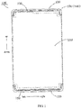
- a conductive cover assembly 100 of a terminal 200 and the terminal 200 according to embodiments of the present disclosure will be described below in detail with reference to FIG. 1 to FIG. 6 .
- the conductive cover assembly 100 of the terminal 200 includes: a first portion 110, a second portion 120, a conductive suspension strip 130, a connector 150, a conductive member 160, and a resilient sheet 170 adapted to be electrically connected to a signal source 221.
- the conductive cover assembly 100 means that body parts of the conductive cover assembly 100 (e.g., the first portion 110 and the second portion 120) may be made of a conductive material, or may be made of an insulating material, with conductive treatment (such as application of a conductive coating) performed on the insulating cover assembly.
- the conductive cover assembly 100 may mean that the body parts of the cover assembly (e.g., the first portion 110 and the second portion 120) have an electrical conducting property, and may also mean that part of the areas of the body parts (e.g., the first portion 110 and the second portion 120) on the cover assembly has an electrical conducting property.
- the material and electrical conducting property of the conductive suspension strip 130 can be understood in a similar manner, and relevant details are not described herein.
- the conductive suspension strip 130 is located within the gap 101, and a length of the conductive suspension strip 130 is equal to a length of the gap 101.
- the conductive suspension strip 130 has a same shape and size as the gap 101.
- An insulating layer 140 is disposed between the conductive suspension strip 130 and the first portion 110 and also between the conductive suspension strip 130 and the second portion 120. It can be understood that the conductive cover assembly 100 is provided with the gap 101 which runs through two opposite sidewalls of the conductive cover assembly 100 (for example, as shown in FIG.
- the gap 101 runs through the left sidewall and the right sidewall of the conductive cover assembly 100) to divide the conductive cover assembly 100 into the first portion 110 and the second portion 120 and within which the conductive suspension strip 130 is provided. That is, the first portion 110, the conductive suspension strip 130, and the second portion 120 are arranged in an alternate and spaced manner; and the first portion 110 is insulatively connected to the conductive suspension strip 130, and the conductive suspension strip 130 is insulatively connected to the second portion 120, thereby forming a complete conductive cover assembly 100
- the connector 150 spans the gap 101 and is connected to the first portion 110 and the second portion 120, respectively.
- the connector 150 is an insulating connector, and an injection-molded connector 150 which can be formed on the conductive cover assembly 100 via an injection molding process, whereby processing of the conductive cover assembly 100 can be simplified.
- the connector 150 can be configured not only to connect the first portion 110 and the second portion 120, but also to support other components within the conductive cover assembly 100 (e.g., the conductive member 160).
- the conductive member 160 is attached to a side of the connector 150 away from the gap 101 (for example, the conductive member 160 is attached to a front side surface of the connector 150); an end of the conductive member 160 is electrically connected to the first portion 110; and the resilient sheet 170 is electrically connected to the conductive member 160.
- a signal source 221, an antenna switch 225, an earthing point 224 (or called a feed point) and a tuner (for example, a first tuner 223 or a second tuner 230) of antenna assembly 220 all can be electrically connected to the conductive member 160 through the resilient sheet 170.
- the conductive member 160 may be connected to the first portion 110 by welding.
- the connection between the conductive member 160 and the first portion 110 can be achieved by a welding process, for example, ultrasonic welding or laser welding.
- the connection between the conductive member 160 and the first portion 110 can also be achieved in a manner of a lock screw.
- the conductive cover assembly 100 of the terminal 200 it is possible to enhance stability of connection between the conductive member 160 and the connector 150, by attaching the conductive member 160 to the connector 150 and making electrical connection to the conductive member 160 via the resilient sheet 170. Furthermore, by connecting the first portion 110 and the second portion 120 via the connector 150 and further making electrical connection to the first portion 110 via the conductive member 160, the first portion 110 can directly serve as a part of the antenna assembly 220 to improve signal radiation capability and anti-interference capability of the antenna assembly 220, thereby making it possible to enhance intensity of the antenna signals and simplify the structure of the terminal 200.
- a thickness of the insulating layer 140 may be 0.05 mm to 0.5 mm. It has been experimentally verified that, when the thickness of the insulating layer 140 is 0.1 mm to 0.5 mm, the terminal 200 has a relatively good signal radiation performance and the strongest anti-interference capability. Further, it has been experimentally verified that, when the thickness of the insulating layer 140 is 0.3 mm, the terminal 200 has a better signal radiation performance and a stronger anti-interference capability.
- the conductive suspension strip 130 includes: two first straight sections 131 spaced apart, a second straight section 132, and two vertical connection sections 133.
- the second straight section 132 is located between the two first straight sections 131.
- the second straight section 132 is located on a side of the first straight section 131 and is parallel to the first straight section 131.
- An extending direction of the vertical connection sections 133 is perpendicular to an extending direction of the first straight sections 131. Two ends of each of the vertical connection sections 133 are connected to the corresponding first straight section 131 and second straight section 132, respectively.
- the conductive suspension strip 130 extends in a left-right direction; the first straight section 131 and the second straight section 132 extend in a horizontal direction (i.e., extend in a left-right direction as shown in FIG. 1 and FIG. 3 ); the first straight section 131 and the second straight section 132 are spaced apart in an up-down direction (i.e., an up-down direction as shown in FIG. 1 and FIG. 3 ); and the two first straight sections 131 are located at two ends of the second straight section 132 in the left-right direction.
- the vertical connection section 133 extends in an up-down direction (i.e., an up-down direction as shown in FIG. 1 and FIG.
- one of the two vertical connection sections 133 is configured to connect the first straight section 131 located on the left side and the left end of the second straight section 132; and the other of the two vertical connection sections 133 is configured to connect the first straight section 131 located on the right side and the right end of the second straight section 132.
- a right angle 134 is formed between a sidewall face of the first straight section 131 oriented toward the first portion 110 and the corresponding vertical connection section 133.
- the first straight section 131 on the left side is connected to the vertical connection section 133 on the left side; and a right angle 134 is formed at a position where the sidewall face of the first straight section 131 oriented toward the first portion 110 (i.e., the upper sidewall face of the first straight section 131 located as shown in FIG. 3 ) and the vertical connection section 133 are connected. It has been experimentally verified that, the anti-interference capability of the antenna assembly 220 will be enhanced when the right angle 134 is formed between the sidewall face of the first straight section 131 oriented toward the first portion 110 and the corresponding vertical connection section 133.
- a round corner 135 is formed between a sidewall face of the first straight section 131 oriented toward the second portion 120 and the corresponding vertical connection section 133.
- the first straight section 131 on the left side is connected to the vertical connection section 133 on the left side.
- a round corner 135 is formed at a position where the sidewall face of the first straight section 131 oriented toward the second portion 120 (i.e., the lower sidewall face of the first straight section 131 located as shown in FIG. 1 ) is connected to the vertical connection section 133. It has been experimentally verified that, the anti-interference capability of the antenna assembly 220 will be enhanced when the round corner 135 is formed between the sidewall face of the first straight section 131 oriented toward the second portion 120 and the corresponding vertical connection section 133.
- a smooth transition connection 136 is provided between the second straight section 132 and the vertical connection sections 133. It can be understood that the smooth transition connection 136 is provided between the vertical connection section 133 on the left side and the left end of the second straight section 132, and the smooth transition connection 136 is also provided between the vertical connection section 133 on the right side and the right end of the second straight section 132. For example, as shown in FIG. 3 , the vertical connection section 133 on the left side and the left end of the second straight section 132 are connected to each other via a circular arc line segment (i.e., the smooth transition connection 136). It has been experimentally verified that, the anti-interference capability of the antenna assembly 220 can be enhanced when the second straight section 132 is smoothly connected to the vertical connection section 133.
- the conductive cover assembly 100 includes a cover body and a cover side plate surrounding a periphery of the cover body.
- the cover body and the cover side plate define a mounting cavity 102 with one side open.
- the connector 150, the conductive member 160 and the resilient sheet 170 are all located within the mounting cavity 102.
- the first portion 110 is configured as the cover side plate, and the second portion 120 is configured as the cover body.
- gaps 101 on the conductive cover assembly 100 may be two, and the two gaps 101 may divide the conductive cover assembly 100 into two first portions 110 and one second portion 120, where the two first portions 110 are located at two upper and lower ends of the second portion 120, and each of the gaps 101 is provided with a conductive suspension strip 130.
- a length of the conductive suspension strip 130 is equal to a length of the gap 101. That is to say, the conductive suspension strip 130 has a same shape and size as the gap 101.
- a rear surface (i.e., a surface on the rear side as shown in FIG. 5 ) of the conductive suspension strip 130 is flush with a rear surface (i.e., a surface on the rear side as shown in FIG. 5 ) of the second portion 120.
- a thickness of the conductive suspension strip 130 in a front-rear direction is smaller than a thickness of the second portion 120 in a front-rear direction (i.e., a front-rear direction as shown in FIG. 5 ).
- the conductive suspension strip 130 can extend into the gap 101 in the front-rear direction.
- a depth with which the conductive suspension strip 130 extends into the gap 101 is smaller than a depth of the gap 101 in the front-rear direction.
- the terminal 200 includes an antenna assembly 220 and the conductive cover assembly 100 of the terminal 200 as described above.
- terminal includes
- a device that is configured to receive/transmit communication signals via a wireline connection, such as via a public-switched telephone network (PSTN), digital subscriber line (DSL), digital cable, a direct cable connection, and/or another data connection/network, and/or via a wireless interface with, for example, a cellular network, a wireless local area network (WLAN), a digital television network such as a DVB-H network, a satellite network, an AM-FM broadcast transmitter, and/or another communication terminal.
- PSTN public-switched telephone network
- DSL digital subscriber line
- WLAN wireless local area network
- DVB-H digital television network
- satellite network such as a DVB-H network
- AM-FM broadcast transmitter and/or another communication terminal.
- a communication terminal that is set to communicate over a wireless interface may be referred to as a "wireless communication terminal", “wireless terminal” and/or “mobile terminal”.
- the mobile terminal include, but are not limited to, a satellite or cellular radiotelephone; a Personal Communications System (PCS) terminal that may combine a cellular radiotelephone with data processing, facsimile and data communications capabilities; a PDA that can include a radiotelephone, pager, Internet/intranet access, Web browser, organizer, calendar and/or a global positioning system (GPS) receiver; and a conventional laptop and/or palmtop receiver or other appliance that includes a radiotelephone transceiver.
- PCS Personal Communications System
- GPS global positioning system
- the antenna assembly 220 is electrically connected to the first portion 110.
- the first portion 110 can directly serve as a part of the antenna assembly 220 to improve the signal radiating capability and anti-interference capability of the antenna assembly 220, thereby making it possible to enhance intensity of the antenna signals and simplify the structure of the terminal 200.
- the terminal 200 it is possible to enhance stability of connection between the conductive member 160 and the connector 150, by attaching the conductive member 160 to the connector 150 and making electrical connection to the conductive member 160 via the resilient sheet 170. Furthermore, by connecting the first portion 110 and the second portion 120 via the connector 150 and further making electrical connection to the first portion 110 via the conductive member 160, the first portion 110 can directly serve as a part of the antenna assembly 220 to improve the signal radiation capability and anti-interference capability of the antenna assembly 220, thereby making it possible to enhance intensity of the antenna signals and simplify the structure of the terminal 200.
- the terminal 200 may further include an externally-connected seat 210.
- the externally-connected seat 210 can be disposed on the conductive cover assembly 100 and spaced apart from the first portion 110 of the conductive cover assembly 100.
- the externally-connected seat 210 may be a component such as an earphone jack, a USB jack, a fingerprint recognition component 210a, a speaker component, or a side key 210b.
- the externally-connected seat 210 and the first portion 110 when the externally-connected seat 210 and the first portion 110 are arranged in a spaced manner, the externally-connected seat 210 can be spaced apart from the first portion 110 by utilizing spatial separation, that is, when the externally-connected seat 210 and the first portion 110 are required to be connected, a manner of indirect connection can be used to realize connection between the externally-connected seat 210 and the first portion 110.
- the externally-connected seat 210 and the first portion 110 are not in contact and connection with each other.
- the externally-connected seat 210 and the first portion 110 may also be spaced apart by some means such as magnetic bead or inductor 226 isolation.
- the USB jack can be arranged to be spatially spaced apart from the first portion 110.
- a minimum space between the USB jack and the first portion 110 can be 0.5 mm; and an audio line of the speaker component can be isolated by some means such as magnetic bead or inductor 226 separation.
- the antenna assembly 220 is electrically connected to the first portion 110.
- the antenna assembly 220 includes: a signal source 221, a matching circuit 222, a first tuner 223 (or called tuner 1), and a second tuner 230 (or called tuner 2).
- a first tuner 223 or called tuner 1
- a second tuner 230 or called tuner 2
- an end of the matching circuit 222 is electrically connected to the resilient sheet 170, and the other end is electrically connected to the signal source 221 and the resilient sheet 170.
- the first tuner 223 is electrically connected to the first portion 110 and the earthing point 224 respectively; the second tuner 230 and the first tuner 223 are spaced apart; and the second tuner 230 is electrically connected to the first portion 110 and the earthing point 224, respectively.
- the tuner is a switch or a variable capacitor.
- the first tuner 223 and the second tuner may be antenna switches 225, i.e., SWITCH1 or SWITCH2.
- the tuner 1 is configured for medium-high frequency tuning (coordination frequency is 1710M-2170M HZ)
- the tuner 2 is configured for low-frequency tuning (coordination frequency is 700M-960M HZ).
- the tuner 1 In the right hand grip (for example, a state in which the user's right hand holds the terminal 200), the tuner 1 is configured to adjust the antenna characteristic impedance, and the tuner 2 is configured for the antenna low frequency (coordination frequency is 700M-960M HZ) and medium-high frequency (coordination frequency is 1710M-2170M HZ) tuning.
- the tuner 2 In the left hand grip (for example, the state in which the user's left hand holds the terminal 200), the tuner 2 is configured to adjust the antenna characteristic impedance, and the tuner 1 is configured for the antenna low frequency (coordinating frequency is 700M-960M HZ) and medium-high frequency (coordinating frequency is 1710M-2170M HZ) tuning. Freedom of the antenna and radiation performance under the grip of the user's hands are improved by switching among the three states.
- the terminal 200 applicable to the present disclosure is introduced with a mobile phone as an example.
- the mobile phone may include components such as a radio frequency circuit, a memory, an input unit, a wireless fidelity (WiFi) module, a display screen assembly 260, a sensor, an audio circuit, a processor, a projection unit, a camera assembly 240, and a battery, etc.
- the camera assembly 240 can be a single-camera assembly or a dual-camera assembly.
- the radio frequency circuit can be used for receiving and transmitting signals during transmission and reception of information or talking, and particularly, after receiving downlink information from the base station, has the received downlink information processed by the processor.
- uplink data of the mobile phone is transmitted to the base station.
- the radio frequency circuit includes, but is not limited to, communication antennas, at least one amplifier, transceiver, coupler, low noise amplifier, duplexer, and the like. Further, the radio frequency circuit can also communicate with a network and other devices through wireless communication.
- the above wireless communication may use any communication standard or protocol, including but not limited to, Global System for Mobile communication (GSM), General Packet Radio Service (GPRS), and Code Division Multiple Access (CDMA), Wideband Code Division Multiple Access (WCDMA), Long Term Evolution (LTE), e-mail, Short Messaging Service (SMS), and the like.
- GSM Global System for Mobile communication
- GPRS General Packet Radio Service
- CDMA Code Division Multiple Access
- WCDMA Wideband Code Division Multiple Access
- LTE Long Term Evolution
- SMS Short Messaging Service
- the memory can be configured to store software programs and modules, and the processor executes various functional applications and data processing of the mobile phone by running the software programs and modules stored in the memory.
- the memory may mainly include a program storage area and a data storage area, where the program storage area may store an operating system, application(s) required by at least one function (such as a sound playing function, an image playing function, etc.), and the like; and the data storage area can store data (such as audio data, phone book, etc.) created according to use of the mobile phone.
- the memory may include a high-speed random access memory, and may also include a non-volatile memory such as at least one magnetic disk storage means, a flash memory means, or other volatile solid-state storage means.
- the input unit can be configured to receive inputted numeric or character information and to generate key signals related to user setting and function control of the mobile phone.
- the input unit may include a touch control panel and other input devices.
- the touch control panel also called a touch screen, may collect touch operations of the user thereon or near thereto (such as operations on the touch control panel or near to the touch control panel conducted by the user with any suitable object or accessory, such as finger, a touch-pen, or the like), and drive corresponding connection device according to a preset program.
- the touch control panel may include two parts, namely, a touch detection device and a touch controller. Therein, the touch detection device detects the user's touch orientation and a signal induced by the touch operation, and transmits the signal to the touch controller.
- the touch controller receives touch information from the touch detection device, converts the touch information into contact point coordinates then sent to the processor, and can receive and execute commands from the processor.
- the touch control panel can be implemented with various types such as resistive type, capacitive type, infrared type, and surface acoustic wave type etc..
- the input unit may also include other input devices in addition to the touch control panel. Specifically, other input devices may include, but are not limited to, one or more of a physical keyboard, function keys (such as volume control press-key, on-off press-key, etc.), trackballs, mouse, joystick, and the like.
- the terminal 200 can include a conductive cover assembly 100 and a front cover 250 which together define a mounting cavity 102.
- a display screen assembly 260 which is embedded on the front cover 250, can be configured to display information inputted by the user or information provided for the user as well as various menus of the mobile phone.
- the display screen assembly 260 can include a display panel.
- the display panel can be configured in various forms such as a Liquid Crystal Display (LCD), an Organic Light-Emitting Diode (OLED), or the like.
- the touch control panel may cover the display panel. After detecting a touch operation thereon or near thereto, the touch control panel transmits the touch operation to the processor to determine a type of the touch event, and then the processor provides corresponding visual output on the display panel according to the type of the touch event.
- the position of the visual output recognizable by the human eyes in the display panel can be used as a "display area" described later.
- the touch control panel and the display panel can be used as two independent components to realize input and output functions of the mobile phone.
- the touch control panel and the display panel can also be integrated to realize the input and output functions of the mobile phone.
- the mobile phone can also include at least one type of sensor, such as a posture sensor, a light sensor, a fingerprint recognition component 210a, and other sensors.
- the posture sensor may also be called a motion sensor, and as one type of the motion sensor, a gravity sensor may be listed.
- the gravity sensor uses an elastic-sensitive element to form a cantilever type shifter and drives the electrical contacts by an energy-storing spring made of an elastic-sensitive element, thereby realizing converting gravity variation into gravity into electrical signal variation.
- an accelerometer sensor can be listed.
- the accelerometer sensor can detect magnitudes of acceleration in each direction (usually three axes), and when being stationary, it can detect the magnitude and direction of gravity, which can be used to identify applications of posture of the mobile phone (such as horizontal and vertical screen switching, related games, magnetometer posture calibration), and vibration recognition related functions (such as pedometer, tapping), etc.
- the motion sensors listed above may be used as the element to obtain the "posture parameter" described below, but the application is not limited herein, and other sensors capable of obtaining the "posture parameter" fall within the protection scope of the present disclosure, for example, a gyroscope or the like.
- the working principle and data processing procedure of the gyroscope can be similar to the prior art. For the sake of conciseness, a detailed description thereof is omitted herein.
- sensors other sensors such as a barometer, a hygrometer, a thermometer, and an infrared sensor, and the like can also be configured, and details are not described herein.
- the light sensor may include an ambient light sensor and a proximity sensor, where the ambient light sensor may adjust brightness of the display panel according to intensity of the ambient light rays, and the proximity sensor may turn off the display panel and/or the backlight when the mobile phone moves to the ear.
- Audio circuit, speaker, and microphone can provide an audio interface between the user and the mobile phone.
- the audio circuit can transmit a converted electrical signal of the received audio data to the speaker which converts the electrical signal into a sound signal to be outputted.
- the microphone converts the collected sound signal into an electrical signal which is received by the audio circuit and converted into audio data; and the audio data is then outputted to the processor for processing, before being sent via the radio frequency circuit to another mobile phone, for example, or the audio data is outputted to a memory for further processing.
- WIFI belongs to a short-distance wireless transmission technology.
- the mobile phone can help the user receive and send emails, browse web pages and access streaming media and the like through the WIFI module, which provides the user with wireless broadband Internet access.
- the processor is a control center of the mobile phone, and connects various parts of the entire mobile phone by using various interfaces and lines, and executes various functions of the mobile phone and processes data to monitor the mobile phone as a whole, by running or executing software programs and/or modules stored in the memory and calling data stored in the memory.
- the processor may include one or more processing units.
- the processor may integrate an application processor and a modem processor.
- the application processor mainly processes an operating system, a user interface, an application, etc.
- the modem processor mainly processes wireless communications.
- modem processor may also not be integrated into the processor.
- the processor can serve as an implementation element of the processing unit described above to execute the same or similar functions as the processing unit.
- the mobile phone also includes a power supply (such as a battery) that supplies power to the various components.
- the power supply can be logically connected to the processor through a power supply management system to realize managing functions such as charging, discharging, and power management etc. through the power supply management system.
- the mobile phone may further include a bluetooth module and the like, and details are not described herein again.
- the mobile phone is only an example of the terminal 200 device, and is not particularly limited by the present disclosure.
- the present disclosure can be applied to an electronic device such as a mobile phone or a tablet computer, which is not limited herein.
Landscapes
- Engineering & Computer Science (AREA)
- Computer Networks & Wireless Communication (AREA)
- Signal Processing (AREA)
- Telephone Set Structure (AREA)
Applications Claiming Priority (3)
| Application Number | Priority Date | Filing Date | Title |
|---|---|---|---|
| CN201710004668.7A CN106785353B (zh) | 2017-01-04 | 2017-01-04 | 终端的导电盖体组件及终端 |
| CN201720009588.6U CN206332162U (zh) | 2017-01-04 | 2017-01-04 | 终端的导电盖体组件及终端 |
| PCT/CN2017/119532 WO2018126985A1 (zh) | 2017-01-04 | 2017-12-28 | 终端的导电盖体组件及终端 |
Publications (3)
| Publication Number | Publication Date |
|---|---|
| EP3553882A1 true EP3553882A1 (de) | 2019-10-16 |
| EP3553882A4 EP3553882A4 (de) | 2019-11-20 |
| EP3553882B1 EP3553882B1 (de) | 2021-10-27 |
Family
ID=62789293
Family Applications (1)
| Application Number | Title | Priority Date | Filing Date |
|---|---|---|---|
| EP17890606.1A Not-in-force EP3553882B1 (de) | 2017-01-04 | 2017-12-28 | Leitfähige blendenkomponente eines endgeräts sowie endgerät |
Country Status (3)
| Country | Link |
|---|---|
| US (1) | US10826171B2 (de) |
| EP (1) | EP3553882B1 (de) |
| WO (1) | WO2018126985A1 (de) |
Families Citing this family (4)
| Publication number | Priority date | Publication date | Assignee | Title |
|---|---|---|---|---|
| TWD192003S (zh) * | 2017-05-11 | 2018-08-01 | 廣東歐珀移動通信有限公司 | 手機之部分 |
| USD940127S1 (en) | 2018-04-23 | 2022-01-04 | Apple Inc. | Electronic device |
| US11632449B2 (en) * | 2020-12-09 | 2023-04-18 | Motorola Mobility Llc | Antenna configuration for a foldable device |
| CN113612005B (zh) * | 2021-07-20 | 2022-12-13 | 西安电子科技大学 | 一种加载引向器的4元gps抗干扰天线阵、移动通信系统 |
Family Cites Families (14)
| Publication number | Priority date | Publication date | Assignee | Title |
|---|---|---|---|---|
| KR100973659B1 (ko) * | 2010-02-02 | 2010-08-02 | 마상영 | 안테나가 내장된 무선 휴대단말기 케이스 및 그 제조방법 |
| CN202374260U (zh) | 2011-12-22 | 2012-08-08 | 联想移动通信科技有限公司 | 一种移动通信终端 |
| CN103178344A (zh) * | 2013-04-01 | 2013-06-26 | 昆山睿翔讯通通信技术有限公司 | 多频段金属后盖手机天线 |
| CN103367865B (zh) | 2013-07-15 | 2017-04-12 | 华为终端有限公司 | 天线的制作方法及终端设备 |
| CN104540341A (zh) * | 2014-10-23 | 2015-04-22 | 深圳富泰宏精密工业有限公司 | 壳体、应用该壳体的电子装置及其制作方法 |
| CN104540340B (zh) * | 2014-10-23 | 2018-09-25 | 深圳富泰宏精密工业有限公司 | 壳体、应用该壳体的电子装置及其制作方法 |
| CN204216211U (zh) * | 2014-11-12 | 2015-03-18 | 瑞声声学科技(苏州)有限公司 | 移动通讯终端 |
| CN105530787A (zh) * | 2014-12-26 | 2016-04-27 | 比亚迪股份有限公司 | 一种通讯设备金属外壳及其制备方法 |
| CN105098332B (zh) * | 2015-08-12 | 2018-09-07 | 宇龙计算机通信科技(深圳)有限公司 | 一种天线系统以及通信电子设备 |
| WO2017035730A1 (zh) | 2015-08-31 | 2017-03-09 | 华为技术有限公司 | 一种缝隙天线和终端设备 |
| CN105789827B (zh) * | 2016-03-18 | 2018-01-23 | 广东欧珀移动通信有限公司 | 天线装置及移动终端 |
| CN105932398B (zh) * | 2016-05-16 | 2017-11-17 | 广东欧珀移动通信有限公司 | 壳体、天线装置及移动终端 |
| CN106785353B (zh) * | 2017-01-04 | 2023-04-21 | Oppo广东移动通信有限公司 | 终端的导电盖体组件及终端 |
| CN206332162U (zh) * | 2017-01-04 | 2017-07-14 | 广东欧珀移动通信有限公司 | 终端的导电盖体组件及终端 |
-
2017
- 2017-12-28 EP EP17890606.1A patent/EP3553882B1/de not_active Not-in-force
- 2017-12-28 WO PCT/CN2017/119532 patent/WO2018126985A1/zh not_active Ceased
-
2019
- 2019-07-03 US US16/503,445 patent/US10826171B2/en not_active Expired - Fee Related
Also Published As
| Publication number | Publication date |
|---|---|
| US10826171B2 (en) | 2020-11-03 |
| US20190326667A1 (en) | 2019-10-24 |
| EP3553882B1 (de) | 2021-10-27 |
| EP3553882A4 (de) | 2019-11-20 |
| WO2018126985A1 (zh) | 2018-07-12 |
Similar Documents
| Publication | Publication Date | Title |
|---|---|---|
| CN106785353B (zh) | 终端的导电盖体组件及终端 | |
| CN207818883U (zh) | 天线组件及电子设备 | |
| US10826171B2 (en) | Conductive cover assembly of terminal and terminal | |
| CN106785436A (zh) | 导电盖体、壳体组件和终端 | |
| CN110233328A (zh) | 移动终端 | |
| TWI664778B (zh) | 導電蓋體、殼體元件和終端 | |
| CN206332162U (zh) | 终端的导电盖体组件及终端 | |
| CN206332181U (zh) | 导电盖体、壳体组件和终端 | |
| CN107908224B (zh) | 电子设备的壳体组件及电子设备 | |
| WO2019201217A1 (zh) | 电子设备 | |
| CN110165451B (zh) | Btb连接器的固定装置及移动终端 | |
| CN108234718B (zh) | 电子装置的壳体组件及电子装置 | |
| CN107910659B (zh) | 电路板组件和具有其的终端 | |
| CN108696605B (zh) | 电子设备 | |
| CN207491154U (zh) | 电子设备的外壳组件及电子设备 | |
| CN206251151U (zh) | 用于终端的屏蔽组件及终端 | |
| CN106790837B (zh) | 终端、壳体组件及壳体组件的制造方法 | |
| CN207560562U (zh) | 电子装置的壳体组件及电子装置 | |
| AU2018339943B2 (en) | Housing assembly for terminal and terminal with housing assembly | |
| CN106852048A (zh) | 电子装置的壳体组件及电子装置 | |
| CN107911963B (zh) | 电子设备的壳体组件及电子设备 | |
| CN207459205U (zh) | 弹片和具有其的终端 | |
| HK1236681A1 (en) | Conductive cover, housing assembly and terminal | |
| HK1236681A (en) | Conductive cover, housing assembly and terminal | |
| CN107896258A (zh) | 终端的壳体组件及终端 |
Legal Events
| Date | Code | Title | Description |
|---|---|---|---|
| STAA | Information on the status of an ep patent application or granted ep patent |
Free format text: STATUS: THE INTERNATIONAL PUBLICATION HAS BEEN MADE |
|
| PUAI | Public reference made under article 153(3) epc to a published international application that has entered the european phase |
Free format text: ORIGINAL CODE: 0009012 |
|
| STAA | Information on the status of an ep patent application or granted ep patent |
Free format text: STATUS: REQUEST FOR EXAMINATION WAS MADE |
|
| 17P | Request for examination filed |
Effective date: 20190711 |
|
| AK | Designated contracting states |
Kind code of ref document: A1 Designated state(s): AL AT BE BG CH CY CZ DE DK EE ES FI FR GB GR HR HU IE IS IT LI LT LU LV MC MK MT NL NO PL PT RO RS SE SI SK SM TR |
|
| AX | Request for extension of the european patent |
Extension state: BA ME |
|
| A4 | Supplementary search report drawn up and despatched |
Effective date: 20191023 |
|
| RIC1 | Information provided on ipc code assigned before grant |
Ipc: H01Q 1/24 20060101AFI20191017BHEP Ipc: H04M 1/02 20060101ALI20191017BHEP |
|
| RAP1 | Party data changed (applicant data changed or rights of an application transferred) |
Owner name: GUANGDONG OPPO MOBILE TELECOMMUNICATIONS CORP., LT |
|
| DAV | Request for validation of the european patent (deleted) | ||
| DAX | Request for extension of the european patent (deleted) | ||
| GRAP | Despatch of communication of intention to grant a patent |
Free format text: ORIGINAL CODE: EPIDOSNIGR1 |
|
| STAA | Information on the status of an ep patent application or granted ep patent |
Free format text: STATUS: GRANT OF PATENT IS INTENDED |
|
| INTG | Intention to grant announced |
Effective date: 20210708 |
|
| GRAS | Grant fee paid |
Free format text: ORIGINAL CODE: EPIDOSNIGR3 |
|
| GRAA | (expected) grant |
Free format text: ORIGINAL CODE: 0009210 |
|
| STAA | Information on the status of an ep patent application or granted ep patent |
Free format text: STATUS: THE PATENT HAS BEEN GRANTED |
|
| AK | Designated contracting states |
Kind code of ref document: B1 Designated state(s): AL AT BE BG CH CY CZ DE DK EE ES FI FR GB GR HR HU IE IS IT LI LT LU LV MC MK MT NL NO PL PT RO RS SE SI SK SM TR |
|
| REG | Reference to a national code |
Ref country code: GB Ref legal event code: FG4D |
|
| REG | Reference to a national code |
Ref country code: CH Ref legal event code: EP |
|
| REG | Reference to a national code |
Ref country code: AT Ref legal event code: REF Ref document number: 1442668 Country of ref document: AT Kind code of ref document: T Effective date: 20211115 |
|
| REG | Reference to a national code |
Ref country code: DE Ref legal event code: R096 Ref document number: 602017048519 Country of ref document: DE |
|
| REG | Reference to a national code |
Ref country code: IE Ref legal event code: FG4D |
|
| REG | Reference to a national code |
Ref country code: LT Ref legal event code: MG9D |
|
| REG | Reference to a national code |
Ref country code: NL Ref legal event code: MP Effective date: 20211027 |
|
| REG | Reference to a national code |
Ref country code: AT Ref legal event code: MK05 Ref document number: 1442668 Country of ref document: AT Kind code of ref document: T Effective date: 20211027 |
|
| PG25 | Lapsed in a contracting state [announced via postgrant information from national office to epo] |
Ref country code: RS Free format text: LAPSE BECAUSE OF FAILURE TO SUBMIT A TRANSLATION OF THE DESCRIPTION OR TO PAY THE FEE WITHIN THE PRESCRIBED TIME-LIMIT Effective date: 20211027 Ref country code: LT Free format text: LAPSE BECAUSE OF FAILURE TO SUBMIT A TRANSLATION OF THE DESCRIPTION OR TO PAY THE FEE WITHIN THE PRESCRIBED TIME-LIMIT Effective date: 20211027 Ref country code: FI Free format text: LAPSE BECAUSE OF FAILURE TO SUBMIT A TRANSLATION OF THE DESCRIPTION OR TO PAY THE FEE WITHIN THE PRESCRIBED TIME-LIMIT Effective date: 20211027 Ref country code: BG Free format text: LAPSE BECAUSE OF FAILURE TO SUBMIT A TRANSLATION OF THE DESCRIPTION OR TO PAY THE FEE WITHIN THE PRESCRIBED TIME-LIMIT Effective date: 20220127 Ref country code: AT Free format text: LAPSE BECAUSE OF FAILURE TO SUBMIT A TRANSLATION OF THE DESCRIPTION OR TO PAY THE FEE WITHIN THE PRESCRIBED TIME-LIMIT Effective date: 20211027 |
|
| PG25 | Lapsed in a contracting state [announced via postgrant information from national office to epo] |
Ref country code: IS Free format text: LAPSE BECAUSE OF FAILURE TO SUBMIT A TRANSLATION OF THE DESCRIPTION OR TO PAY THE FEE WITHIN THE PRESCRIBED TIME-LIMIT Effective date: 20220227 Ref country code: SE Free format text: LAPSE BECAUSE OF FAILURE TO SUBMIT A TRANSLATION OF THE DESCRIPTION OR TO PAY THE FEE WITHIN THE PRESCRIBED TIME-LIMIT Effective date: 20211027 Ref country code: PT Free format text: LAPSE BECAUSE OF FAILURE TO SUBMIT A TRANSLATION OF THE DESCRIPTION OR TO PAY THE FEE WITHIN THE PRESCRIBED TIME-LIMIT Effective date: 20220228 Ref country code: PL Free format text: LAPSE BECAUSE OF FAILURE TO SUBMIT A TRANSLATION OF THE DESCRIPTION OR TO PAY THE FEE WITHIN THE PRESCRIBED TIME-LIMIT Effective date: 20211027 Ref country code: NO Free format text: LAPSE BECAUSE OF FAILURE TO SUBMIT A TRANSLATION OF THE DESCRIPTION OR TO PAY THE FEE WITHIN THE PRESCRIBED TIME-LIMIT Effective date: 20220127 Ref country code: NL Free format text: LAPSE BECAUSE OF FAILURE TO SUBMIT A TRANSLATION OF THE DESCRIPTION OR TO PAY THE FEE WITHIN THE PRESCRIBED TIME-LIMIT Effective date: 20211027 Ref country code: LV Free format text: LAPSE BECAUSE OF FAILURE TO SUBMIT A TRANSLATION OF THE DESCRIPTION OR TO PAY THE FEE WITHIN THE PRESCRIBED TIME-LIMIT Effective date: 20211027 Ref country code: HR Free format text: LAPSE BECAUSE OF FAILURE TO SUBMIT A TRANSLATION OF THE DESCRIPTION OR TO PAY THE FEE WITHIN THE PRESCRIBED TIME-LIMIT Effective date: 20211027 Ref country code: GR Free format text: LAPSE BECAUSE OF FAILURE TO SUBMIT A TRANSLATION OF THE DESCRIPTION OR TO PAY THE FEE WITHIN THE PRESCRIBED TIME-LIMIT Effective date: 20220128 Ref country code: ES Free format text: LAPSE BECAUSE OF FAILURE TO SUBMIT A TRANSLATION OF THE DESCRIPTION OR TO PAY THE FEE WITHIN THE PRESCRIBED TIME-LIMIT Effective date: 20211027 |
|
| REG | Reference to a national code |
Ref country code: DE Ref legal event code: R097 Ref document number: 602017048519 Country of ref document: DE |
|
| PG25 | Lapsed in a contracting state [announced via postgrant information from national office to epo] |
Ref country code: SM Free format text: LAPSE BECAUSE OF FAILURE TO SUBMIT A TRANSLATION OF THE DESCRIPTION OR TO PAY THE FEE WITHIN THE PRESCRIBED TIME-LIMIT Effective date: 20211027 Ref country code: SK Free format text: LAPSE BECAUSE OF FAILURE TO SUBMIT A TRANSLATION OF THE DESCRIPTION OR TO PAY THE FEE WITHIN THE PRESCRIBED TIME-LIMIT Effective date: 20211027 Ref country code: RO Free format text: LAPSE BECAUSE OF FAILURE TO SUBMIT A TRANSLATION OF THE DESCRIPTION OR TO PAY THE FEE WITHIN THE PRESCRIBED TIME-LIMIT Effective date: 20211027 Ref country code: MC Free format text: LAPSE BECAUSE OF FAILURE TO SUBMIT A TRANSLATION OF THE DESCRIPTION OR TO PAY THE FEE WITHIN THE PRESCRIBED TIME-LIMIT Effective date: 20211027 Ref country code: EE Free format text: LAPSE BECAUSE OF FAILURE TO SUBMIT A TRANSLATION OF THE DESCRIPTION OR TO PAY THE FEE WITHIN THE PRESCRIBED TIME-LIMIT Effective date: 20211027 Ref country code: DK Free format text: LAPSE BECAUSE OF FAILURE TO SUBMIT A TRANSLATION OF THE DESCRIPTION OR TO PAY THE FEE WITHIN THE PRESCRIBED TIME-LIMIT Effective date: 20211027 Ref country code: CZ Free format text: LAPSE BECAUSE OF FAILURE TO SUBMIT A TRANSLATION OF THE DESCRIPTION OR TO PAY THE FEE WITHIN THE PRESCRIBED TIME-LIMIT Effective date: 20211027 |
|
| REG | Reference to a national code |
Ref country code: CH Ref legal event code: PL |
|
| PLBE | No opposition filed within time limit |
Free format text: ORIGINAL CODE: 0009261 |
|
| STAA | Information on the status of an ep patent application or granted ep patent |
Free format text: STATUS: NO OPPOSITION FILED WITHIN TIME LIMIT |
|
| REG | Reference to a national code |
Ref country code: BE Ref legal event code: MM Effective date: 20211231 |
|
| GBPC | Gb: european patent ceased through non-payment of renewal fee |
Effective date: 20220127 |
|
| 26N | No opposition filed |
Effective date: 20220728 |
|
| PG25 | Lapsed in a contracting state [announced via postgrant information from national office to epo] |
Ref country code: LU Free format text: LAPSE BECAUSE OF NON-PAYMENT OF DUE FEES Effective date: 20211228 Ref country code: IE Free format text: LAPSE BECAUSE OF NON-PAYMENT OF DUE FEES Effective date: 20211228 Ref country code: GB Free format text: LAPSE BECAUSE OF NON-PAYMENT OF DUE FEES Effective date: 20220127 Ref country code: AL Free format text: LAPSE BECAUSE OF FAILURE TO SUBMIT A TRANSLATION OF THE DESCRIPTION OR TO PAY THE FEE WITHIN THE PRESCRIBED TIME-LIMIT Effective date: 20211027 |
|
| PG25 | Lapsed in a contracting state [announced via postgrant information from national office to epo] |
Ref country code: SI Free format text: LAPSE BECAUSE OF FAILURE TO SUBMIT A TRANSLATION OF THE DESCRIPTION OR TO PAY THE FEE WITHIN THE PRESCRIBED TIME-LIMIT Effective date: 20211027 Ref country code: FR Free format text: LAPSE BECAUSE OF NON-PAYMENT OF DUE FEES Effective date: 20211231 Ref country code: BE Free format text: LAPSE BECAUSE OF NON-PAYMENT OF DUE FEES Effective date: 20211231 |
|
| PG25 | Lapsed in a contracting state [announced via postgrant information from national office to epo] |
Ref country code: LI Free format text: LAPSE BECAUSE OF NON-PAYMENT OF DUE FEES Effective date: 20211231 Ref country code: CH Free format text: LAPSE BECAUSE OF NON-PAYMENT OF DUE FEES Effective date: 20211231 |
|
| PGFP | Annual fee paid to national office [announced via postgrant information from national office to epo] |
Ref country code: DE Payment date: 20220621 Year of fee payment: 6 |
|
| PG25 | Lapsed in a contracting state [announced via postgrant information from national office to epo] |
Ref country code: IT Free format text: LAPSE BECAUSE OF FAILURE TO SUBMIT A TRANSLATION OF THE DESCRIPTION OR TO PAY THE FEE WITHIN THE PRESCRIBED TIME-LIMIT Effective date: 20211027 |
|
| P01 | Opt-out of the competence of the unified patent court (upc) registered |
Effective date: 20230412 |
|
| PG25 | Lapsed in a contracting state [announced via postgrant information from national office to epo] |
Ref country code: CY Free format text: LAPSE BECAUSE OF FAILURE TO SUBMIT A TRANSLATION OF THE DESCRIPTION OR TO PAY THE FEE WITHIN THE PRESCRIBED TIME-LIMIT Effective date: 20211027 |
|
| PG25 | Lapsed in a contracting state [announced via postgrant information from national office to epo] |
Ref country code: HU Free format text: LAPSE BECAUSE OF FAILURE TO SUBMIT A TRANSLATION OF THE DESCRIPTION OR TO PAY THE FEE WITHIN THE PRESCRIBED TIME-LIMIT; INVALID AB INITIO Effective date: 20171228 |
|
| PG25 | Lapsed in a contracting state [announced via postgrant information from national office to epo] |
Ref country code: MK Free format text: LAPSE BECAUSE OF FAILURE TO SUBMIT A TRANSLATION OF THE DESCRIPTION OR TO PAY THE FEE WITHIN THE PRESCRIBED TIME-LIMIT Effective date: 20211027 |
|
| PG25 | Lapsed in a contracting state [announced via postgrant information from national office to epo] |
Ref country code: TR Free format text: LAPSE BECAUSE OF FAILURE TO SUBMIT A TRANSLATION OF THE DESCRIPTION OR TO PAY THE FEE WITHIN THE PRESCRIBED TIME-LIMIT Effective date: 20211027 |
|
| REG | Reference to a national code |
Ref country code: DE Ref legal event code: R119 Ref document number: 602017048519 Country of ref document: DE |
|
| PG25 | Lapsed in a contracting state [announced via postgrant information from national office to epo] |
Ref country code: MT Free format text: LAPSE BECAUSE OF FAILURE TO SUBMIT A TRANSLATION OF THE DESCRIPTION OR TO PAY THE FEE WITHIN THE PRESCRIBED TIME-LIMIT Effective date: 20211027 |
|
| PG25 | Lapsed in a contracting state [announced via postgrant information from national office to epo] |
Ref country code: DE Free format text: LAPSE BECAUSE OF NON-PAYMENT OF DUE FEES Effective date: 20240702 |
|
| PG25 | Lapsed in a contracting state [announced via postgrant information from national office to epo] |
Ref country code: DE Free format text: LAPSE BECAUSE OF NON-PAYMENT OF DUE FEES Effective date: 20240702 |