EP3553865A1 - Kollektorplatte und redox-flow-batterie - Google Patents
Kollektorplatte und redox-flow-batterie Download PDFInfo
- Publication number
- EP3553865A1 EP3553865A1 EP17878754.5A EP17878754A EP3553865A1 EP 3553865 A1 EP3553865 A1 EP 3553865A1 EP 17878754 A EP17878754 A EP 17878754A EP 3553865 A1 EP3553865 A1 EP 3553865A1
- Authority
- EP
- European Patent Office
- Prior art keywords
- collector plate
- electrode
- electrolyte
- surface roughness
- flow battery
- Prior art date
- Legal status (The legal status is an assumption and is not a legal conclusion. Google has not performed a legal analysis and makes no representation as to the accuracy of the status listed.)
- Withdrawn
Links
- 239000003792 electrolyte Substances 0.000 claims abstract description 66
- 230000003746 surface roughness Effects 0.000 claims abstract description 59
- 239000003014 ion exchange membrane Substances 0.000 claims description 24
- 230000002093 peripheral effect Effects 0.000 claims description 17
- 239000012774 insulation material Substances 0.000 claims description 13
- 239000007788 liquid Substances 0.000 description 25
- 230000035699 permeability Effects 0.000 description 20
- OKTJSMMVPCPJKN-UHFFFAOYSA-N Carbon Chemical compound [C] OKTJSMMVPCPJKN-UHFFFAOYSA-N 0.000 description 17
- 229920000049 Carbon (fiber) Polymers 0.000 description 13
- 239000004917 carbon fiber Substances 0.000 description 13
- 238000006243 chemical reaction Methods 0.000 description 12
- 239000000463 material Substances 0.000 description 12
- 229910052799 carbon Inorganic materials 0.000 description 9
- 230000007423 decrease Effects 0.000 description 7
- 239000002041 carbon nanotube Substances 0.000 description 6
- 229910021393 carbon nanotube Inorganic materials 0.000 description 6
- 239000000835 fiber Substances 0.000 description 6
- 229920000642 polymer Polymers 0.000 description 6
- 239000011248 coating agent Substances 0.000 description 5
- NBIIXXVUZAFLBC-UHFFFAOYSA-N Phosphoric acid Chemical compound OP(O)(O)=O NBIIXXVUZAFLBC-UHFFFAOYSA-N 0.000 description 4
- 239000004020 conductor Substances 0.000 description 4
- 230000003247 decreasing effect Effects 0.000 description 4
- 229920005989 resin Polymers 0.000 description 4
- 239000011347 resin Substances 0.000 description 4
- 239000000243 solution Substances 0.000 description 4
- 238000000576 coating method Methods 0.000 description 3
- 150000001875 compounds Chemical class 0.000 description 3
- 238000005259 measurement Methods 0.000 description 3
- 230000001681 protective effect Effects 0.000 description 3
- 125000000020 sulfo group Chemical group O=S(=O)([*])O[H] 0.000 description 3
- KXGFMDJXCMQABM-UHFFFAOYSA-N 2-methoxy-6-methylphenol Chemical compound [CH]OC1=CC=CC([CH])=C1O KXGFMDJXCMQABM-UHFFFAOYSA-N 0.000 description 2
- QAOWNCQODCNURD-UHFFFAOYSA-N Sulfuric acid Chemical compound OS(O)(=O)=O QAOWNCQODCNURD-UHFFFAOYSA-N 0.000 description 2
- 239000002253 acid Substances 0.000 description 2
- 229910000147 aluminium phosphate Inorganic materials 0.000 description 2
- 238000000151 deposition Methods 0.000 description 2
- 229910002804 graphite Inorganic materials 0.000 description 2
- 239000010439 graphite Substances 0.000 description 2
- 238000009413 insulation Methods 0.000 description 2
- 238000004898 kneading Methods 0.000 description 2
- 238000000034 method Methods 0.000 description 2
- 238000012986 modification Methods 0.000 description 2
- 230000004048 modification Effects 0.000 description 2
- 239000003973 paint Substances 0.000 description 2
- 239000002245 particle Substances 0.000 description 2
- 239000005011 phenolic resin Substances 0.000 description 2
- 229920001568 phenolic resin Polymers 0.000 description 2
- 230000008569 process Effects 0.000 description 2
- 238000003860 storage Methods 0.000 description 2
- TXEYQDLBPFQVAA-UHFFFAOYSA-N tetrafluoromethane Chemical compound FC(F)(F)F TXEYQDLBPFQVAA-UHFFFAOYSA-N 0.000 description 2
- 239000004215 Carbon black (E152) Substances 0.000 description 1
- 229920000557 Nafion® Polymers 0.000 description 1
- XHCLAFWTIXFWPH-UHFFFAOYSA-N [O-2].[O-2].[O-2].[O-2].[O-2].[V+5].[V+5] Chemical compound [O-2].[O-2].[O-2].[O-2].[O-2].[V+5].[V+5] XHCLAFWTIXFWPH-UHFFFAOYSA-N 0.000 description 1
- 239000007864 aqueous solution Substances 0.000 description 1
- 239000006229 carbon black Substances 0.000 description 1
- 238000005341 cation exchange Methods 0.000 description 1
- 230000008021 deposition Effects 0.000 description 1
- 230000000694 effects Effects 0.000 description 1
- 230000004907 flux Effects 0.000 description 1
- 125000000524 functional group Chemical group 0.000 description 1
- 229930195733 hydrocarbon Natural products 0.000 description 1
- 150000002430 hydrocarbons Chemical class 0.000 description 1
- 150000002500 ions Chemical class 0.000 description 1
- 238000004519 manufacturing process Methods 0.000 description 1
- 239000011159 matrix material Substances 0.000 description 1
- 239000012528 membrane Substances 0.000 description 1
- VNWKTOKETHGBQD-UHFFFAOYSA-N methane Chemical compound C VNWKTOKETHGBQD-UHFFFAOYSA-N 0.000 description 1
- 150000007522 mineralic acids Chemical class 0.000 description 1
- 238000000465 moulding Methods 0.000 description 1
- 229920000620 organic polymer Polymers 0.000 description 1
- 238000007254 oxidation reaction Methods 0.000 description 1
- 239000012466 permeate Substances 0.000 description 1
- -1 phosphoric acid Chemical class 0.000 description 1
- 239000011148 porous material Substances 0.000 description 1
- 239000000047 product Substances 0.000 description 1
- 230000009257 reactivity Effects 0.000 description 1
- 238000006722 reduction reaction Methods 0.000 description 1
- 230000001105 regulatory effect Effects 0.000 description 1
- 238000012546 transfer Methods 0.000 description 1
- 238000013519 translation Methods 0.000 description 1
- 229910001935 vanadium oxide Inorganic materials 0.000 description 1
Images


Classifications
-
- H—ELECTRICITY
- H01—ELECTRIC ELEMENTS
- H01M—PROCESSES OR MEANS, e.g. BATTERIES, FOR THE DIRECT CONVERSION OF CHEMICAL ENERGY INTO ELECTRICAL ENERGY
- H01M8/00—Fuel cells; Manufacture thereof
- H01M8/02—Details
- H01M8/0202—Collectors; Separators, e.g. bipolar separators; Interconnectors
- H01M8/0258—Collectors; Separators, e.g. bipolar separators; Interconnectors characterised by the configuration of channels, e.g. by the flow field of the reactant or coolant
- H01M8/026—Collectors; Separators, e.g. bipolar separators; Interconnectors characterised by the configuration of channels, e.g. by the flow field of the reactant or coolant characterised by grooves, e.g. their pitch or depth
-
- H—ELECTRICITY
- H01—ELECTRIC ELEMENTS
- H01M—PROCESSES OR MEANS, e.g. BATTERIES, FOR THE DIRECT CONVERSION OF CHEMICAL ENERGY INTO ELECTRICAL ENERGY
- H01M8/00—Fuel cells; Manufacture thereof
- H01M8/02—Details
- H01M8/0202—Collectors; Separators, e.g. bipolar separators; Interconnectors
-
- H—ELECTRICITY
- H01—ELECTRIC ELEMENTS
- H01M—PROCESSES OR MEANS, e.g. BATTERIES, FOR THE DIRECT CONVERSION OF CHEMICAL ENERGY INTO ELECTRICAL ENERGY
- H01M8/00—Fuel cells; Manufacture thereof
- H01M8/18—Regenerative fuel cells, e.g. redox flow batteries or secondary fuel cells
- H01M8/184—Regeneration by electrochemical means
- H01M8/188—Regeneration by electrochemical means by recharging of redox couples containing fluids; Redox flow type batteries
-
- H—ELECTRICITY
- H01—ELECTRIC ELEMENTS
- H01M—PROCESSES OR MEANS, e.g. BATTERIES, FOR THE DIRECT CONVERSION OF CHEMICAL ENERGY INTO ELECTRICAL ENERGY
- H01M8/00—Fuel cells; Manufacture thereof
- H01M8/02—Details
- H01M8/0202—Collectors; Separators, e.g. bipolar separators; Interconnectors
- H01M8/0204—Non-porous and characterised by the material
- H01M8/0213—Gas-impermeable carbon-containing materials
-
- Y—GENERAL TAGGING OF NEW TECHNOLOGICAL DEVELOPMENTS; GENERAL TAGGING OF CROSS-SECTIONAL TECHNOLOGIES SPANNING OVER SEVERAL SECTIONS OF THE IPC; TECHNICAL SUBJECTS COVERED BY FORMER USPC CROSS-REFERENCE ART COLLECTIONS [XRACs] AND DIGESTS
- Y02—TECHNOLOGIES OR APPLICATIONS FOR MITIGATION OR ADAPTATION AGAINST CLIMATE CHANGE
- Y02E—REDUCTION OF GREENHOUSE GAS [GHG] EMISSIONS, RELATED TO ENERGY GENERATION, TRANSMISSION OR DISTRIBUTION
- Y02E60/00—Enabling technologies; Technologies with a potential or indirect contribution to GHG emissions mitigation
- Y02E60/30—Hydrogen technology
- Y02E60/50—Fuel cells
Definitions
- the present invention relates to a collector plate and a redox flow battery.
- a redox flow battery is known as a high-capacity storage battery.
- the redox flow battery includes an ion-exchange membrane that separates an electrolyte, and electrodes that are provided on both sides of the ion-exchange membrane. An oxidation reaction and a reduction reaction simultaneously progress on the electrodes, and thus, the redox flow battery is charged and discharged.
- the electrode is stored in an electrode compartment.
- the redox flow battery operates while the electrolyte is supplied to the electrode compartment and the electrolyte is circulated. Ions in the electrolyte give electrons to the electrodes, and the electrons are transferred to the outside of the redox flow battery. At this time, protons are transferred to the other electrode compartment via the ion-exchange membrane.
- the redox flow battery is charged and discharged by the flowing of the electrons and the protons.
- the redox flow battery is manufactured by sequentially stacking collector plates, the electrodes, and the ion-exchange membrane on top of each other which are separate members, and interposing the collector plates, the electrodes, and the ion-exchange membrane between themselves in a stacking direction (for example, Patent Documents 1 and 2).
- an electrode side surface of the collector plate has a certain level of surface roughness
- a positional shift can be prevented.
- the electrolyte flows on the surface of the collector plate.
- a turbulent flow of the electrolyte may occur, and the electrolyte may stagnate.
- reactions in the battery occur between the electrolyte and the electrode.
- reactions between the electrolyte and the collector plate may occur in a region where the electrolyte stagnates.
- the collector plate is assumed to be used for the transferring of electrons, and is not assumed to serve as an electrode. For this reason, a reaction efficiency of the collector plate in the battery is inferior to that of the electrode, and the redox flow battery cannot exhibit a sufficient performance.
- the present invention has been made in light of the problem, and an object of the present invention is to obtain a collector plate that prevents a positional shift of an electrode during the assembly of a redox flow battery, and prevents an electrolyte from stagnating in an electrode compartment.
- the inventors of the present invention have found that in the case where there is a difference in surface roughness between a first surface of an internal wall on the side of an electrode provided in an electrode compartment and an internal surface through which an electrolyte flows, a positional shift of the electrode during the assembly of a redox flow battery can be prevented, and in addition, the electrolyte can be prevented from stagnating in the electrode compartment.
- the present invention is to provide a collector plate and a redox flow battery hereinbelow to solve the problem.
- a positional shift of the electrode during the assembly of the redox flow battery is prevented. It is considered that the electrolyte can be prevented from stagnating in the electrode compartment, and the cell resistance can be decreased.
- FIG. 1 is a schematic cross-sectional view of a redox flow battery of a first embodiment.
- a redox flow battery 100 shown in FIG. 1 includes: an ion-exchange membrane 10; collector plates 20; and electrodes 30.
- the collector plates 20 and the electrodes 30 are surrounded by a cell frame 40.
- the electrode 30 is provided in an electrode compartment K formed by the ion-exchange membrane 10, the collector plate 20, and the cell frame 40. An electrolyte supplied to the electrode compartment K is prevented from leaking to the outside by the cell frame 40.
- the redox flow battery 100 shown in FIG. 1 has a cell-stack structure where a plurality of cells CE are stacked on top of each other.
- the number of stacks of the cells CE can be appropriately changed depending on applications, and only a single cell may be provided. In the case where the plurality of cells CE are connected together in series, a practical voltage is obtained.
- One cell CE includes the ion-exchange membrane 10; two electrodes 30 servings as a positive electrode and a negative electrode between which the ion-exchange membrane 10 is interposed; and the collector plates 20 between which the two electrodes 30 are interposed.
- a stacking direction of the cell-stack structure where the cells CE are stacked on top of each other may be simply referred to as a "stacking direction", and the direction of a plane vertical to the stacking direction of the cell-stack structure may be simply referred to as an "in-plane direction”.
- a cation-exchange membrane can be preferably used as the ion-exchange membrane 10.
- the material of the ion-exchange membrane 10 include a perfluorocarbon polymer having a sulfo group, a hydrocarbon-based polymer compound having a sulfo group, a polymer compound doped with an inorganic acid such as phosphoric acid, an organic/inorganic hybrid polymer in which a part thereof is substituted with a proton-conductive functional group, and a proton conductor in which a polymer matrix is impregnated with a phosphoric acid solution or a sulfuric acid solution.
- a perfluorocarbon polymer having a sulfo group is preferably used, and a Nafion (registered trademark) is more preferably used.
- the collector plate 20 is a current collector having the function of transferring electrons to or from the electrode 30. In the case where both surfaces of the collector plate 20 can be used as a current collector, the collector plate 20 may be referred to as a bipolar plate.
- the collector plate of the embodiment is more preferably used in a redox flow battery.
- the collector plate 20 can be made from a material having conductivity.
- a conductive material containing carbons can be used.
- the material include conductive resin consisting of graphite and an organic polymer compound, conductive resin in which a part of graphite is substituted with at least one of a carbon black and a diamond-like carbon, a mold material obtained by kneading carbon and resin.
- a mold material obtained by kneading carbon and resin and molding the kneaded product is preferably used.
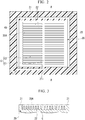
- FIG. 2 is a plan view of the collector plate 20 stored in the cell frame 40 as seen in the stacking direction.
- a plurality of groove portions C are provided on a surface of the collector plate 20 positioned on the side of the ion-exchange membrane 10 (the ion-exchange membrane 10 side surface).
- a wall portion (internal wall 22) is provided at a position between grooves of the plurality of groove portions C. It is also referred that a plurality of the internal walls 22 are provided, and the groove portion C is formed between the internal walls 22.
- a recessed region (portion) 20A is formed on the surface of the collector plate 20 positioned on the side of the ion-exchange membrane 10.
- FIG. 3 is a schematic cross-sectional view of the collector plate as the redox flow battery of the first embodiment is cut along an A-A plane. As shown in FIG.
- the recessed region 20A includes the groove portions C and a region into which a first electrode 31 (will be described later) is fitted.
- a peripheral edge wall 21 may be provided on one surface of the collector plate 20, and the peripheral edge wall 21 defines the recessed region 20A.
- An electrolyte is supplied from an opening portion 21i of the peripheral edge wall 21 into the recessed region 20A surrounded by the peripheral edge wall 21.
- the electrolyte supplied from the opening portion 21i of the peripheral edge wall 21 diffuses throughout the recessed region 20A, and then is exhausted from an exhaust path 23. Because the electrolyte diffuses throughout the recessed region 20A in the in-plane direction, the entire surface of the electrode 30 in the in-plane direction can be used. As a result, the cell resistance of the redox flow battery decreases, and charge and discharge characteristics are improved.
- the internal walls 22 form the groove portions C through which the electrolyte flows in the recessed region 20A. Because the internal walls 22 are provided, the electrolyte is easily supplied throughout the recessed region 20A.
- the shape of the groove portion C and the shape of the internal wall 22 regulated by the plurality of groove portions C are not limited to a specific shape.
- the internal walls 22 shown in FIG. 2 include a first groove portion C1 that is a part of the groove portion C extending from the opening portion 21i in one direction, and second groove portions C2 that are connected with the first groove portion C1 and branch from the first groove portion C1 in a direction intersecting the first groove portion C1.
- the supplied electrolyte flows along the first groove portion C1, and diffuses in the second groove portions C2. That is, the electrolyte easily diffuses in the recessed region 20A in the in-plane direction.
- the configuration of the collector plate 20 is not limited to the configuration shown in FIG. 2 , and the collector plate 20 can have various configurations.
- FIG. 4 is a perspective magnified view of main elements of the collector plate 20.
- a first surface 22a of an internal wall 22 (exposed surface which is positioned on the side (upper side in FIG. 4 ) of one surface, and in which the grooves are formed) is a surface disposed on the side of the ion-exchange membrane 10.
- the first surface 22a of the internal wall 22 is also referred to as a surface that is positioned toward the stacking direction, and faces the electrode 30.
- the first surface is a surface, and is not to be a line or point which connects together the grooves, for example, the cross-sectional shape of the internal wall 22 is not to be a triangular shape.
- the cross-sectional shape of the groove portion C between the internal walls 22 is not limited to a rectangular shape shown in FIG. 4 , and may be a semicircular or triangular shape.
- An internal surface of the groove portion C includes a portion having a surface roughness (Ra) smaller than the surface roughness (Ra) of the first surface 22a of the internal wall 22 positioned on the side of the electrode 30. It is also referred that a portion having a surface roughness (Ra) smaller than the surface roughness (Ra) of the first surface 22a is provided in the internal surface of the groove portion C. With regard to the surface roughness (Ra) of the internal surface of the groove portion, the surface roughness (Ra) of the entire internal surface of the groove portion C is not required to satisfy the above-described relationship.
- the surface roughness (Ra) of a 50% or larger area of region of the internal surface of the groove portion C satisfies the relationship (it is preferable that with regard to a 50% or larger area of region of the internal surface of the groove portion C, the surface roughness (Ra) satisfies the relationship), it is more preferable that the surface roughness (Ra) of an 80% or larger area of region of the internal surface of the groove portion C satisfies the relationship (it is more preferable that with regard to an 80% or larger area of region of the internal surface of the groove portion C, the surface roughness (Ra) satisfies the relationship), and it is further more preferable that the surface roughness (Ra) of the entire internal surface of the groove portion C satisfies the relationship.
- the "50% or larger area” refers to the area of a region of the internal surface in a case where a surface roughness (Ra) is measured at each of ten arbitrary points on each of the internal surface of the groove portion C and the first surface 22a of the internal wall 22, and the surface roughnesses measured at five or more points on the first surface 22a of the internal wall 22 are greater than an average value of the surface roughnesses measured at ten points on the internal surface of the groove portion C.
- a measurement is performed by a non-contact type surface roughness meter.
- the similar definition can be applied to the "80% or larger area" and the "entire surface”.
- the internal surface of the groove portion C corresponds to a side surface 22b of the internal wall 22 and a bottom surface Ca of the groove portion C.
- the surface roughness is an arithmetic surface roughness measured based on JIS B0601. A measurement length is set to 2 mm.
- the arithmetic surface roughness is also referred to as a mean surface roughness or simply a surface roughness.
- the surface roughness (Ra) of a side surface (the side surface 22b of the internal wall 22) of the groove portion C and/or the surface roughness (Ra) of the bottom surface Ca of the groove portion C are smaller than the surface roughness (Ra) of the first surface 22a.
- Turbulence in a flow of the electrolyte causes stagnation of the electrolyte. Reactions between the electrolyte and the collector plate may occur in a region where the electrolyte stagnates.
- the collector plate is assumed to be used for the transferring of electrons, and is not assumed to serve as an electrode. For this reason, the reaction efficiency of the collector plate in the battery is inferior to that of the electrode, and the redox flow battery cannot exhibit a sufficient performance.
- Positioning during the assembly of the redox flow battery 100 is affected by the first surface 22a of the internal wall 22.
- the reason is that the first surface 22a is in direct contact with the electrode 30. That is, in the case where the surface roughness (Ra) of the first surface 22a is set to be greater than the surface roughness (Ra) of the internal surface of the groove portion C, a positional shift of the electrode 30 relative to the collector plate 20 can be prevented, and a high accuracy of positioning can be obtained.
- the electrolyte flows out without passing through the electrode 30, and charge and discharge capacity of the redox flow battery decreases.
- the surface roughness (Ra) of the first surface of the internal wall positioned on the side of the electrode is preferably greater than or equal to 1 ⁇ m and less than or equal to 300 ⁇ m, more preferably greater than or equal to 2 ⁇ m and less than or equal to 250 ⁇ m, and further more preferably greater than or equal to 5 ⁇ m and less than or equal to 200 ⁇ m.
- the surface roughness (Ra) of the first surface 22a of the internal wall 22 is preferably greater than or equal to 1.0 time and less than or equal to 100 times the fiber diameter of carbon fibers (will be described later) of the electrode 30, and more preferably greater than or equal to 1.2 times and less than or equal to 50 times the fiber diameter.
- the contact area between the electrode 30 and the collector plate 20 can be further increased.
- the carbon fibers of the electrode 30 In the case where the fiber diameter of the carbon fibers of the electrode 30 is greatly large relative to the surface roughness (Ra) of the first surface 22a of the internal wall 22, the carbon fibers cannot enter the protrusions and recessions of the first surface 22a. In this case, the carbon fibers are in point contact with the protrusions and recessions of the first surface 22a.
- the surface roughness (Ra) of the first surface 22a of the internal wall 22 is set to be in the above-described range, the carbon fibers can enter the protrusions and recessions, and the carbon fibers are in surface contact with the first surface 22a. As a result, the contact area between the electrode 30 and the collector plate 20 increases.
- the surface roughness (Ra) of the internal surface of the groove portion C is preferably greater than or equal to 0.03 ⁇ m and less than 1 ⁇ m, more preferably greater than or equal to 0.1 ⁇ m and less than or equal to 0.9 ⁇ m, and further more preferably greater than or equal to 0.2 ⁇ m and less than or equal to 0.5 ⁇ m.
- the surface roughness (Ra) of the internal surface of the groove portion C is in the above-described range, the electrolyte can smoothly flow along the groove portion C, and an occurrence of stagnation can be sufficiently prevented.
- each of the internal surface (the side surface 22b and the bottom surface Ca of the groove portion C) of the groove portion C and the first surface 22a of the internal wall 22 in the predetermined range by subjecting the internal surface and the first surface 22a to different processes, respectively in a forming process of the collector plate and the grooves.
- the internal surface (the side surface 22b and the bottom surface Ca of the groove portion C) of the groove portion C is coated with an insulation material.
- the collector plate 20 and the electrolyte do not react with each other even when stagnation occurs.
- the collector plate 20 is required to transfer electrons occurring during reactions between the electrolyte and the electrode 30. For this reason, it is necessary to expose the first surface 22a of the internal wall 22, which is in direct contact with the electrode 30. For this reason, when the side surface 22b of the internal wall 22 and the bottom surface Ca of the groove portion C are coated with the insulation material, attentions are to be paid such that the first surface 22a of the internal wall 22 is not coated with the insulation material.
- one surface of the collector plate 20 is coated with the insulation material.
- the coating of the insulation material may be performed by depositing a film or applying the insulation material. It is possible to obtain a predetermined smooth surface by forming a uniform film by deposition or application (coating). Thereafter, the insulation material coated onto the first surface 22a of the internal wall 22 is removed. It is possible to remove the insulation material by grinding. Before a coating film of the insulation material is formed, a protective film may be formed on the first surface 22a of the internal wall 22, and after an insulation film is formed on the protective film, the protective film may be removed together with the insulation film.
- a material not reacting with the electrolyte is used as the insulation material.
- a fluororesin coating agent or a phenolic resin-based acid-resistant paint can be used.
- a vanadium oxide aqueous solution is widely used in a redox flow battery, and the fluororesin coating agent or the phenolic resin-based acid-resistant paint also has resistance against this solution.
- the width of the internal wall 22 is preferably greater than or equal to 0.5 mm and less than or equal to 30 mm, and more preferably greater than or equal to 0.5 mm and less than or equal to 10 mm.
- the electrolyte is supplied along the groove portion C. For this reason, it is possible to relatively increase the width of the groove portion C by decreasing the width of the internal wall 22. In the case where the width of the groove portion C increases, an occurrence of turbulent flows can be prevented.
- the internal walls 22 form a flow path for a flow of the electrolyte. For this reason, it is possible to ensure sufficient strength by designing the internal wall 22 to have a certain level of thickness. As a result, there are advantages such as being easily processed.
- FIG. 5 is a schematic cross-sectional view as the redox flow battery of the first embodiment is cut along the A-A plane in FIG. 2 .
- a conductive sheet containing carbon fibers can be used as the electrode 30.
- the carbon fiber referred herein is fibrous carbon, and examples of the fibrous carbon include carbon fibers and carbon nanotubes.
- the electrode 30 contains carbon fibers, a contact area between the electrolyte and the electrode 30 increases, and the reactivity of the redox flow battery 100 increases.
- the electrode 30 contains carbon nanotubes having a diameter of less than or equal to 1 ⁇ m
- a fiber diameter of the carbon nanotubes is small, and thus it is possible to increase the contact area between the electrolyte and the electrode 30.
- the electrode 30 contains carbon fibers having a diameter of greater than or equal to 1 ⁇ m
- the conductive sheet becomes strong, and it becomes difficult to break the conductive sheet.
- a carbon felt, a carbon paper, or a carbon-nanotube sheet can be used as the conductive sheet containing carbon fibers.
- a layer of the electrode 30 may be provided in the stacking direction, or a plurality of layers of the electrodes 30 may be provided in the stacking direction.
- the electrode 30 may include the first electrode 31, the second electrode 32, and the liquid outlet layer 33 which are sequentially disposed from the side of the collector plate 20.
- the first electrode 31 is fitted into the recessed region 20A of the collector plate 20, and is present closer to the collector plate 20 than a first surface 21a of the peripheral edge wall 21 (exposed surface on the side of one surface where the internal walls 22 are formed).
- the first electrode 31 is fitted into a region which is surrounded by a side surface of the peripheral edge wall 21 and the first surfaces 22a of the internal walls 22 in the recessed region 20A.
- the first surface 21a of the peripheral edge wall 21 is also referred to as a surface that is positioned toward the stacking direction, and faces the electrode 30 or the ion-exchange membrane 10.
- the second electrode 32 is disposed closer to the ion-exchange membrane 10 than the first surface 21a of the peripheral edge wall 21, and stretches throughout a region surrounded by the cell frame 40.
- the liquid outlet layer 33 stretches throughout the region surrounded by the cell frame 40, and the liquid outlet layer 33 allows the electrolyte to easily flow therethrough more easily than the second electrode 32.
- the liquid outlet layer 33 may be a porous sheet having a large number of holes for permeation of liquid, and may not necessarily have conductivity.
- the first electrode 31 preferably has a liquid permeability greater than that of the second electrode 32.
- the liquid permeability of the first electrode 31 in the in-plane direction is greater than that of the second electrode 32 in the stacking direction, a flow of the electrolyte having flown into the electrode compartment K is restricted by the second electrode 32, and the electrolyte diffuses in the in-plane direction.
- the electrolyte diffuses throughout the recessed region 20A in the in-plane direction, the electrolyte flows to the entire surface of the second electrode 32 more uniformly and easily.
- the liquid outlet layer 33 is porous, and the electrolyte having flown out from the second electrode 32 is guided to the exhaust path by the liquid outlet layer 33.
- the liquid outlet layer 33 preferably has a liquid permeability greater than that of the second electrode 32.
- the liquid permeability of the liquid outlet layer 33 in the in-plane direction is greater than that of the second electrode 32 in the stacking direction, a difference in a flow of the electrolyte in a part of the second electrode 32 in the vicinity of the exhaust path 23 becomes small.
- charge and discharge reactions can occur on the entire surface of the second electrode 32, and the cell resistance decreases.
- the liquid outlet layer 33 is made from a conductive material, and serves as an electrode (third electrode) which is a part of the electrode 30, the cell resistance further decreases.
- the exemplary examples of materials of the first electrode 31 can be used as the conductive material.
- the liquid permeability can be evaluated by a Darcy's law permeability (hereinbelow, may be simply referred to as a permeability).
- a Darcy's law permeability
- the Darcy's law is used to represent the permeability of a porous medium, and is also applied to members other than porous materials for the sake of convenience.
- permeability in a direction where the lowest permeability is observed is adopted.
- a Darcy's law permeability k (m 2 ) is calculated based on a relationship with a permeation flux (m/sec) of a liquid which is represented by the following equation where when the liquid having a viscosity ⁇ (Pa ⁇ sec) permeates through a member having a cross-sectional area S (m 2 ) and a length L (m) at a flow rate Q (m 3 /sec), a pressure difference between a liquid inlet side and a liquid outlet side of the member is represented as ⁇ P (Pa).
- Q S k ⁇ ⁇ ⁇ ⁇ P L
- the permeability of the first electrode 31 is preferably greater than or equal to 100 times, more preferably greater than or equal to 300 times, and further more preferably greater than or equal to 1,000 times that of the second electrode 32.
- the first electrode 31 is made from a carbon felt or a carbon paper which contains carbon fibers having a fiber diameter of greater than or equal to 1 ⁇ m
- the second electrode 32 is made from a carbon-nanotube sheet which contains carbon nanotubes having a fiber diameter of less than or equal to 1 ⁇ m.
- the permeability of the first electrode 31 represents a permeability in the in-plane direction
- the permeability of the second electrode 32 represents a permeability in the stacking direction (normal direction of the in-plane direction).
- the liquid outlet layer 33 preferably has a liquid permeability greater than that of the second electrode 32.
- the reason is that the electrolyte having passed through the second electrode 32 is required to be quickly exhausted to the exhaust path 23.
- the permeability of the liquid outlet layer 33 is preferably greater than or equal to 50 times, more preferably greater than or equal to 100 times, further more preferably greater than or equal to 300 times, and particularly preferably greater than or equal to 1,000 times that of the second electrode 32.
- the exemplary examples of materials of the first electrode 31 can be used as the material of the liquid outlet layer 33.
- the permeability of the liquid outlet layer 33 represents a permeability in the in-plane direction.
- FIG. 6 is a view showing a flow of the electrolyte in the redox flow battery 100 of the first embodiment.
- the electrolyte is supplied into the electrode compartment K of the redox flow battery 100 from an inlet port provided in the cell frame 40.
- the electrolyte supplied into the electrode compartment K reacts with the electrode 30 in the electrode compartment K. Ions occurring at the reactions flow between the electrodes 30 via the ion-exchange membrane 10, and charge and discharge occurs.
- the electrolyte after the reactions is exhausted from an outlet port provided in the cell frame 40.
- the electrolyte is supplied from the opening portion 21i of the peripheral edge wall 21 into the recessed region 20A in the electrode compartment K (flow f11).
- the supplied electrolyte flows along the internal walls 22, and diffuses in the recessed region 20A in the in-plane direction (flow f12). Then the electrolyte passes through the electrode 30, and is exhausted from the exhaust path 23 (flow f13).
- a turbulent flow of the electrolyte and stagnation of the electrolyte can be prevented. For this reason, it is possible to prevent an occurrence of non-assumed reactions such as reactions between the collector plate and the electrolyte, and to increase a reaction efficiency of the redox flow battery. Specifically, the cell resistance of the redox flow battery can be decreased, and charge and discharge characteristics can be improved.
- the redox flow battery of the embodiment it is possible to prevent a positional shift of the electrode relative to the collector plate. For this reason, it is possible to prevent a positional shift of the electrode relative to the collector plate during the assembly of the redox flow battery, and to prevent the electrolyte from flowing out without passing through the electrode. That is, a decrease in the charge and discharge capacity of the redox flow battery can be prevented.
- the present invention can be preferably applied to a redox flow battery of a high-capacity storage battery.
Landscapes
- Life Sciences & Earth Sciences (AREA)
- Engineering & Computer Science (AREA)
- Manufacturing & Machinery (AREA)
- Sustainable Development (AREA)
- Sustainable Energy (AREA)
- Chemical & Material Sciences (AREA)
- Chemical Kinetics & Catalysis (AREA)
- Electrochemistry (AREA)
- General Chemical & Material Sciences (AREA)
- Fuel Cell (AREA)
Applications Claiming Priority (2)
| Application Number | Priority Date | Filing Date | Title |
|---|---|---|---|
| JP2016236718 | 2016-12-06 | ||
| PCT/JP2017/043745 WO2018105634A1 (ja) | 2016-12-06 | 2017-12-06 | 集電板及びレドックスフロー電池 |
Publications (2)
| Publication Number | Publication Date |
|---|---|
| EP3553865A1 true EP3553865A1 (de) | 2019-10-16 |
| EP3553865A4 EP3553865A4 (de) | 2020-07-08 |
Family
ID=62491211
Family Applications (1)
| Application Number | Title | Priority Date | Filing Date |
|---|---|---|---|
| EP17878754.5A Withdrawn EP3553865A4 (de) | 2016-12-06 | 2017-12-06 | Kollektorplatte und redox-flow-batterie |
Country Status (5)
| Country | Link |
|---|---|
| US (1) | US20200075967A1 (de) |
| EP (1) | EP3553865A4 (de) |
| JP (1) | JPWO2018105634A1 (de) |
| CN (1) | CN110024195A (de) |
| WO (1) | WO2018105634A1 (de) |
Families Citing this family (1)
| Publication number | Priority date | Publication date | Assignee | Title |
|---|---|---|---|---|
| US10790531B2 (en) * | 2016-12-06 | 2020-09-29 | Showa Denko K.K. | Collector plate and redox flow battery |
Family Cites Families (10)
| Publication number | Priority date | Publication date | Assignee | Title |
|---|---|---|---|---|
| IT1077612B (it) * | 1977-02-07 | 1985-05-04 | Nora Oronzo Impianti Elettroch | Setto bipolare conduttore per celle elettrochimiche e metodo di preparazione |
| JPH11297338A (ja) * | 1998-04-10 | 1999-10-29 | Nisshinbo Ind Inc | 固体高分子型燃料電地用セパレータ及びその製造方法 |
| JP4747804B2 (ja) * | 2005-11-25 | 2011-08-17 | パナソニック電工株式会社 | 燃料電池用セパレータの製造方法 |
| US9520600B2 (en) * | 2009-09-22 | 2016-12-13 | GM Global Technology Operations LLC | Conductive and hydrophilic bipolar plate coatings and method of making the same |
| JP5964986B2 (ja) | 2011-12-20 | 2016-08-03 | ユナイテッド テクノロジーズ コーポレイションUnited Technologies Corporation | 混合流を用いるフローバッテリ |
| TWI447995B (zh) * | 2011-12-20 | 2014-08-01 | Ind Tech Res Inst | 雙極板與燃料電池 |
| KR101807378B1 (ko) * | 2012-11-09 | 2017-12-08 | 유나이티드 테크놀로지스 코포레이션 | 부식을 제어하기 위한 전기화학 장치 및 방법 |
| WO2014109957A1 (en) * | 2013-01-11 | 2014-07-17 | Graftech International Holdings Inc. | Improved bipolar plate for flow batteries |
| JP2015122231A (ja) * | 2013-12-24 | 2015-07-02 | 住友電気工業株式会社 | レドックスフロー電池 |
| JP6108008B1 (ja) * | 2016-05-30 | 2017-04-05 | 住友電気工業株式会社 | 双極板、セルフレーム及びセルスタック、並びにレドックスフロー電池 |
-
2017
- 2017-12-06 EP EP17878754.5A patent/EP3553865A4/de not_active Withdrawn
- 2017-12-06 US US16/466,403 patent/US20200075967A1/en not_active Abandoned
- 2017-12-06 CN CN201780072137.XA patent/CN110024195A/zh active Pending
- 2017-12-06 WO PCT/JP2017/043745 patent/WO2018105634A1/ja not_active Ceased
- 2017-12-06 JP JP2018555030A patent/JPWO2018105634A1/ja active Pending
Also Published As
| Publication number | Publication date |
|---|---|
| US20200075967A1 (en) | 2020-03-05 |
| WO2018105634A1 (ja) | 2018-06-14 |
| CN110024195A (zh) | 2019-07-16 |
| EP3553865A4 (de) | 2020-07-08 |
| JPWO2018105634A1 (ja) | 2019-10-24 |
Similar Documents
| Publication | Publication Date | Title |
|---|---|---|
| Akuzum et al. | Obstructed flow field designs for improved performance in vanadium redox flow batteries | |
| EP3545579B1 (de) | Bipolarplatten-dichtungsanordnung sowie brennstoffzellenstapel mit einer solchen | |
| EP3346537B1 (de) | Bipolarplatte, zellenrahmen sowie zellenstapel und redox-durchflussbatterie | |
| EP3553859A1 (de) | Kollektorplatte und redox-flow-batterie | |
| EP2884570B1 (de) | Brennstoffzellenseparator und verfahren zur herstellung davon | |
| US20100068588A1 (en) | Membrane-membrane reinforcing membrane assembly, membrane-catalyst layer assembly, membrane-electrode assembly, and polymer electrolyte fuel cell | |
| KR20200030470A (ko) | 전기 화학 반응기 유동 가이드의 제조 프로세스 | |
| TWI648903B (zh) | 氧化還原液流電池 | |
| KR101612740B1 (ko) | 마이크로유체 연료전지 | |
| DE102008038202A1 (de) | PEM-Brennstoffzelle mit verbessertem Wassermanagement | |
| US7749631B2 (en) | Fuel cell separator plate coating | |
| JP7627856B2 (ja) | 燃料電池用触媒層の製造方法および燃料電池の製造方法 | |
| US10707514B2 (en) | Redox flow battery | |
| EP3553865A1 (de) | Kollektorplatte und redox-flow-batterie | |
| US10790531B2 (en) | Collector plate and redox flow battery | |
| EP3553860A1 (de) | Kollektorplatte und redox-flow-batterie | |
| JP7710156B2 (ja) | 膜電極接合体および燃料電池 | |
| CN101416342A (zh) | 用于燃料电池的复合水管理电解质膜 | |
| EP3570354A1 (de) | Stromabnehmerplatte, redox-flow-zelle und verfahren zur herstellung einer redox-flow-zelle | |
| CN107210451A (zh) | 用于制造催化涂覆的膜片的方法以及膜片电极单元和带有这种膜片电极单元的燃料电池堆垛 |
Legal Events
| Date | Code | Title | Description |
|---|---|---|---|
| STAA | Information on the status of an ep patent application or granted ep patent |
Free format text: STATUS: THE INTERNATIONAL PUBLICATION HAS BEEN MADE |
|
| PUAI | Public reference made under article 153(3) epc to a published international application that has entered the european phase |
Free format text: ORIGINAL CODE: 0009012 |
|
| STAA | Information on the status of an ep patent application or granted ep patent |
Free format text: STATUS: REQUEST FOR EXAMINATION WAS MADE |
|
| 17P | Request for examination filed |
Effective date: 20190702 |
|
| AK | Designated contracting states |
Kind code of ref document: A1 Designated state(s): AL AT BE BG CH CY CZ DE DK EE ES FI FR GB GR HR HU IE IS IT LI LT LU LV MC MK MT NL NO PL PT RO RS SE SI SK SM TR |
|
| AX | Request for extension of the european patent |
Extension state: BA ME |
|
| DAV | Request for validation of the european patent (deleted) | ||
| DAX | Request for extension of the european patent (deleted) | ||
| A4 | Supplementary search report drawn up and despatched |
Effective date: 20200609 |
|
| RIC1 | Information provided on ipc code assigned before grant |
Ipc: H01M 8/0258 20160101ALI20200603BHEP Ipc: H01M 8/18 20060101AFI20200603BHEP Ipc: H01M 8/0202 20160101ALI20200603BHEP Ipc: H01M 8/0213 20160101ALN20200603BHEP Ipc: H01M 8/026 20160101ALI20200603BHEP |
|
| STAA | Information on the status of an ep patent application or granted ep patent |
Free format text: STATUS: THE APPLICATION IS DEEMED TO BE WITHDRAWN |
|
| 18D | Application deemed to be withdrawn |
Effective date: 20210112 |